

A Comparison in Combustion Characteristics in a CVCC with Biodiesel Blends

 and
and
Abstract
:1. Introduction
2. Experimental Procedure
2.1. Test Chamber Combustion
2.2. Test Fuels
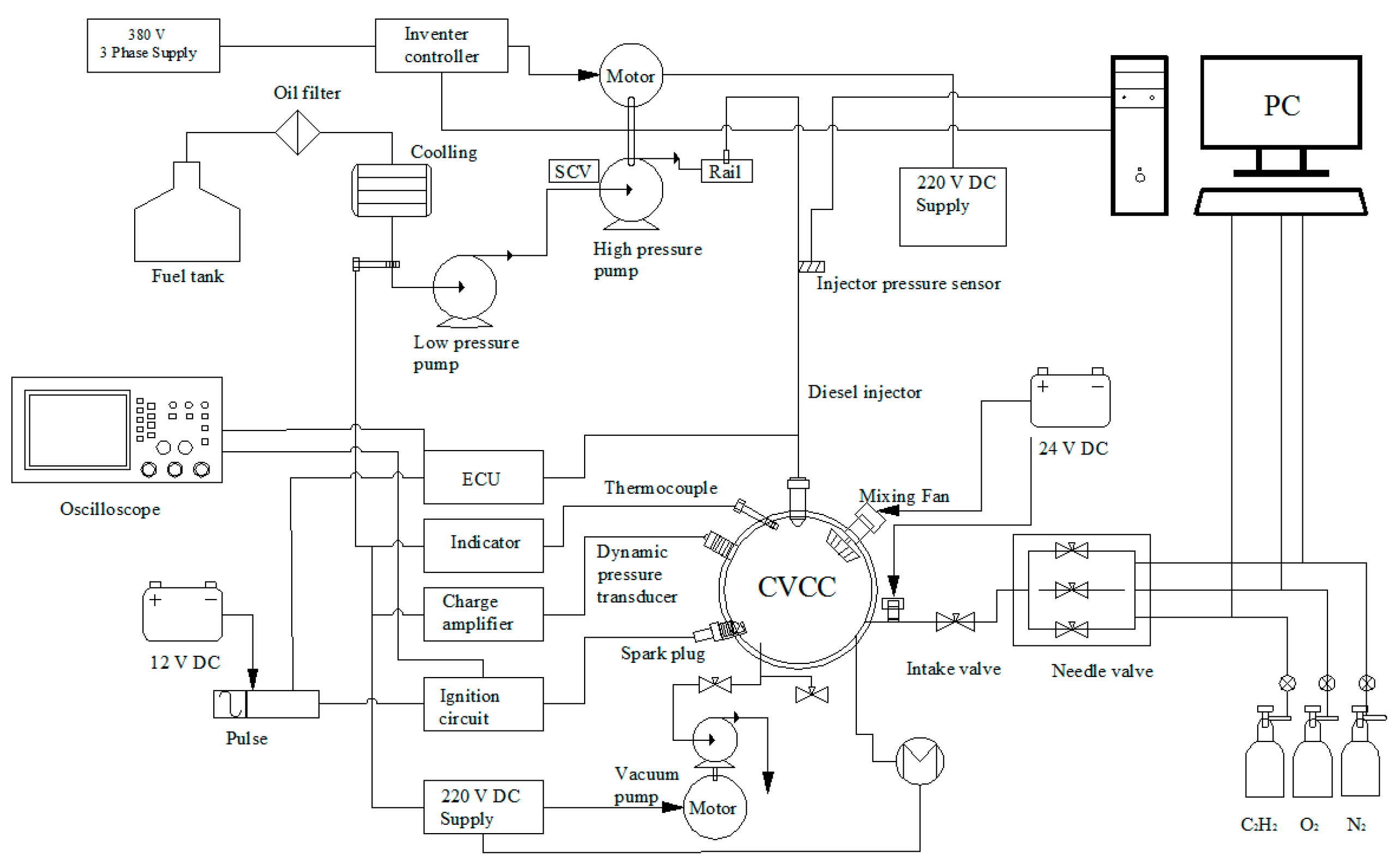
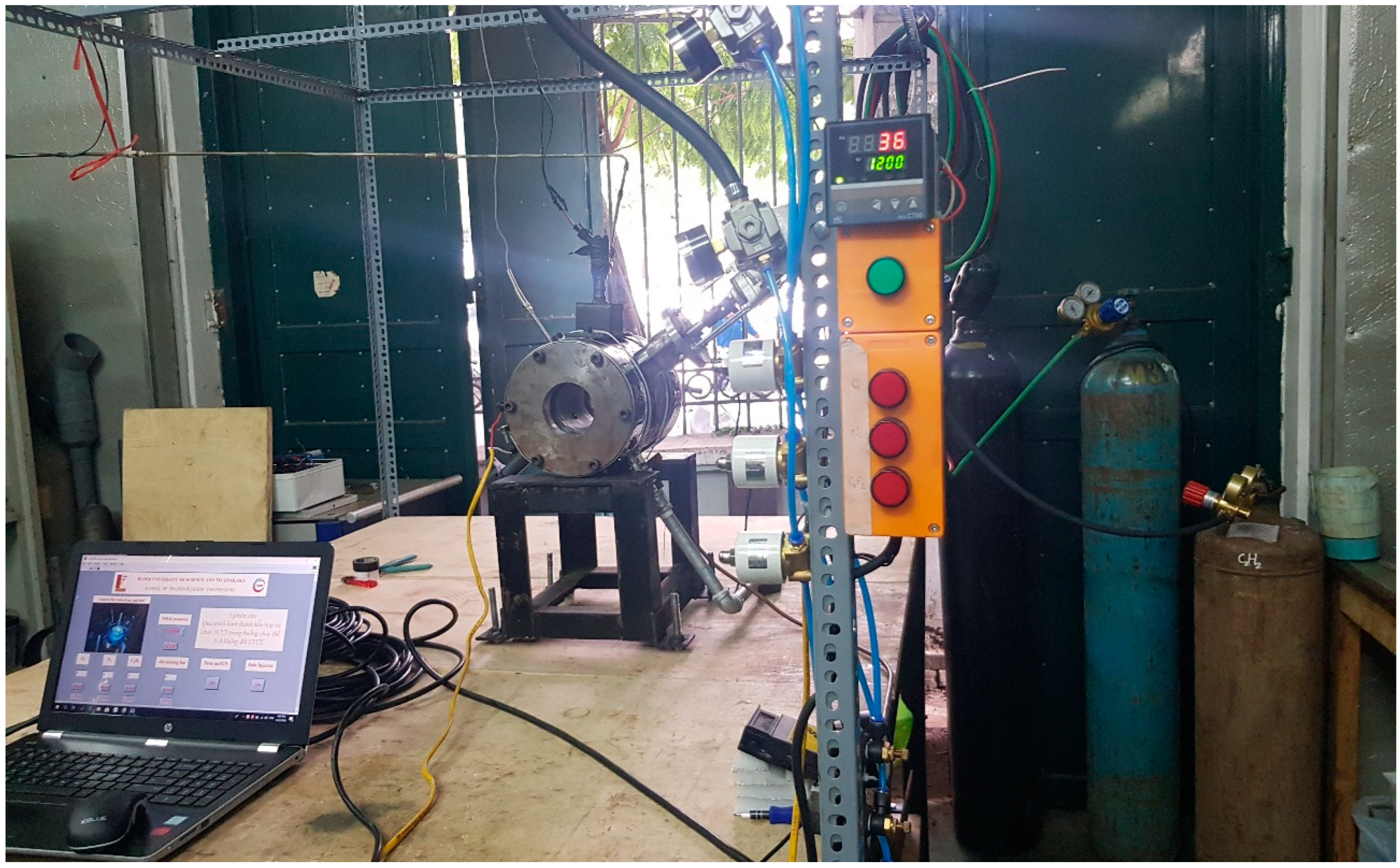
2.3. Test Equipment
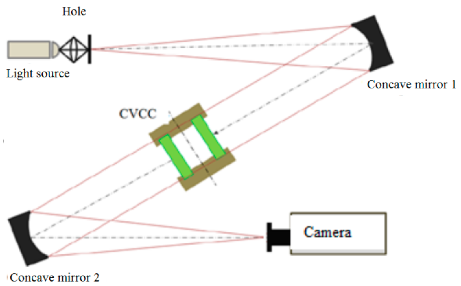
2.4. Experimental Setup
Experimental Layout Diagram
3. Results and Discussion
3.1. Pri-Mixture before Ignition
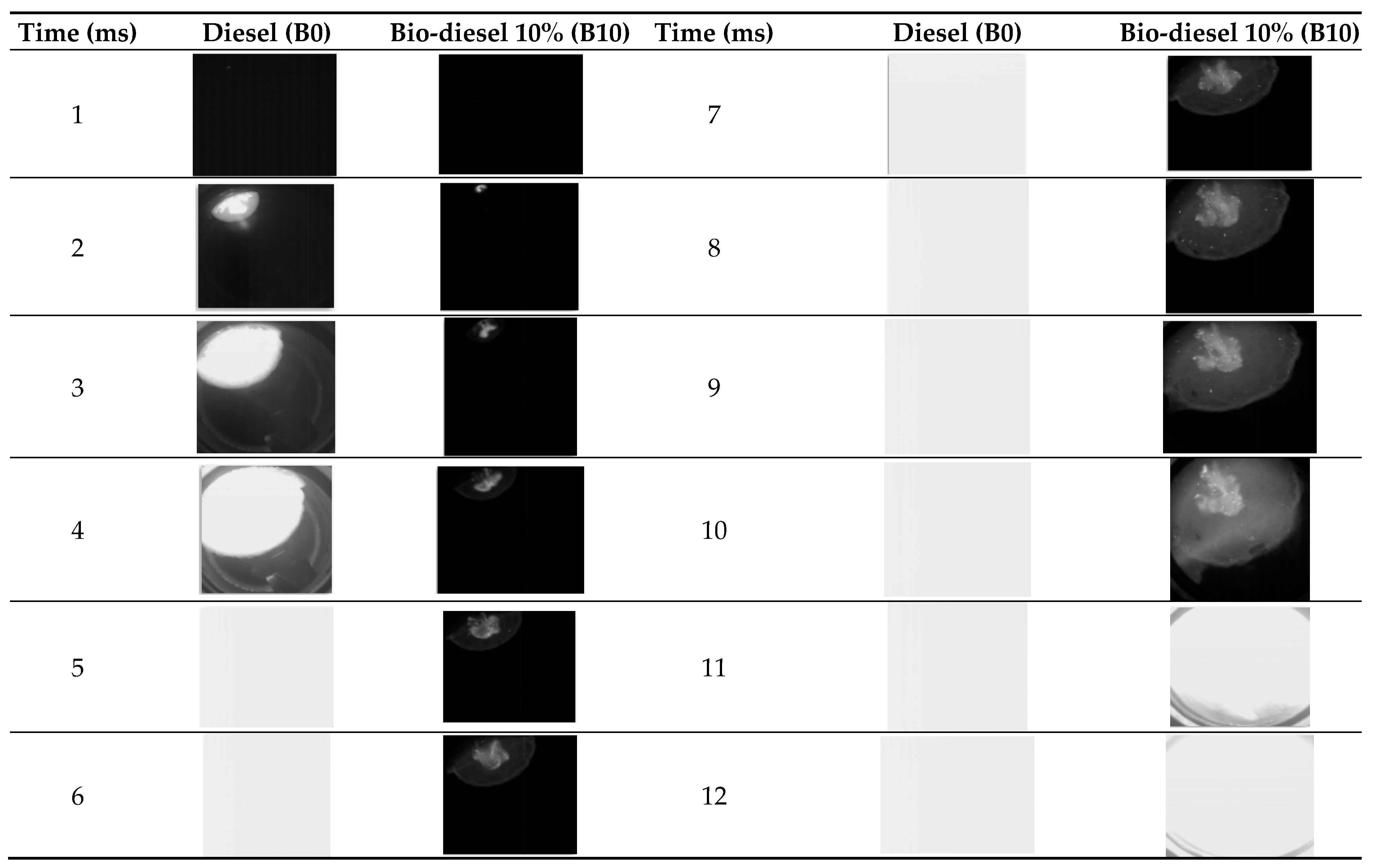
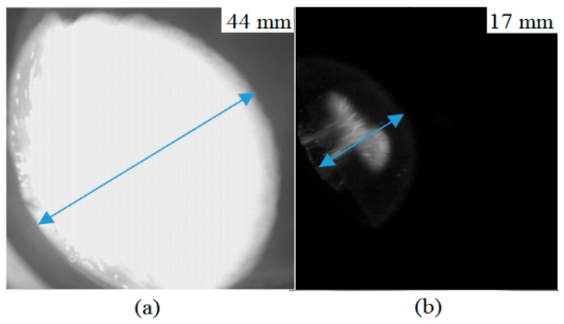
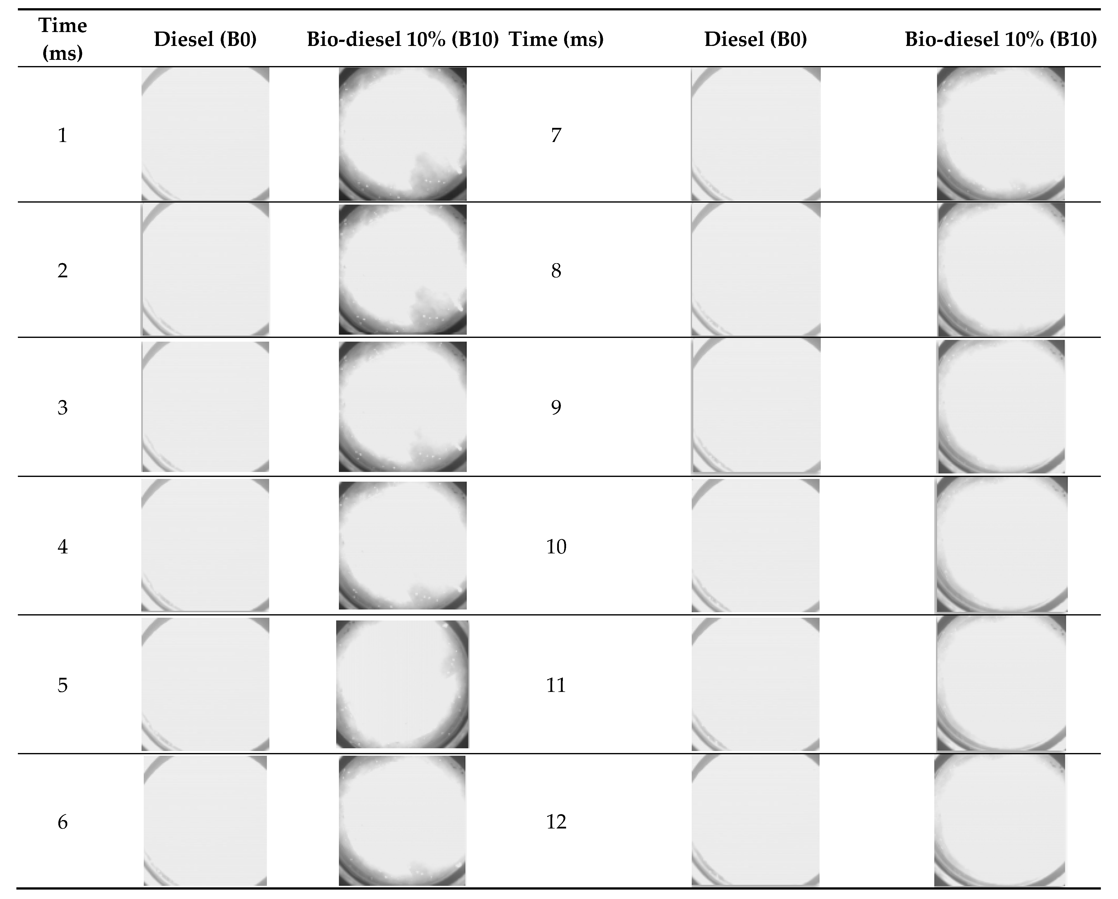
3.1.1. Flame Membrane Development
3.1.2. Evolution of the Pressure in the Cylinder
3.1.3. The Rising Pressure Rate
3.1.4. Heat Release Rate
3.2. The following Mix Is Mixed
3.2.1. Flame Membrane Development
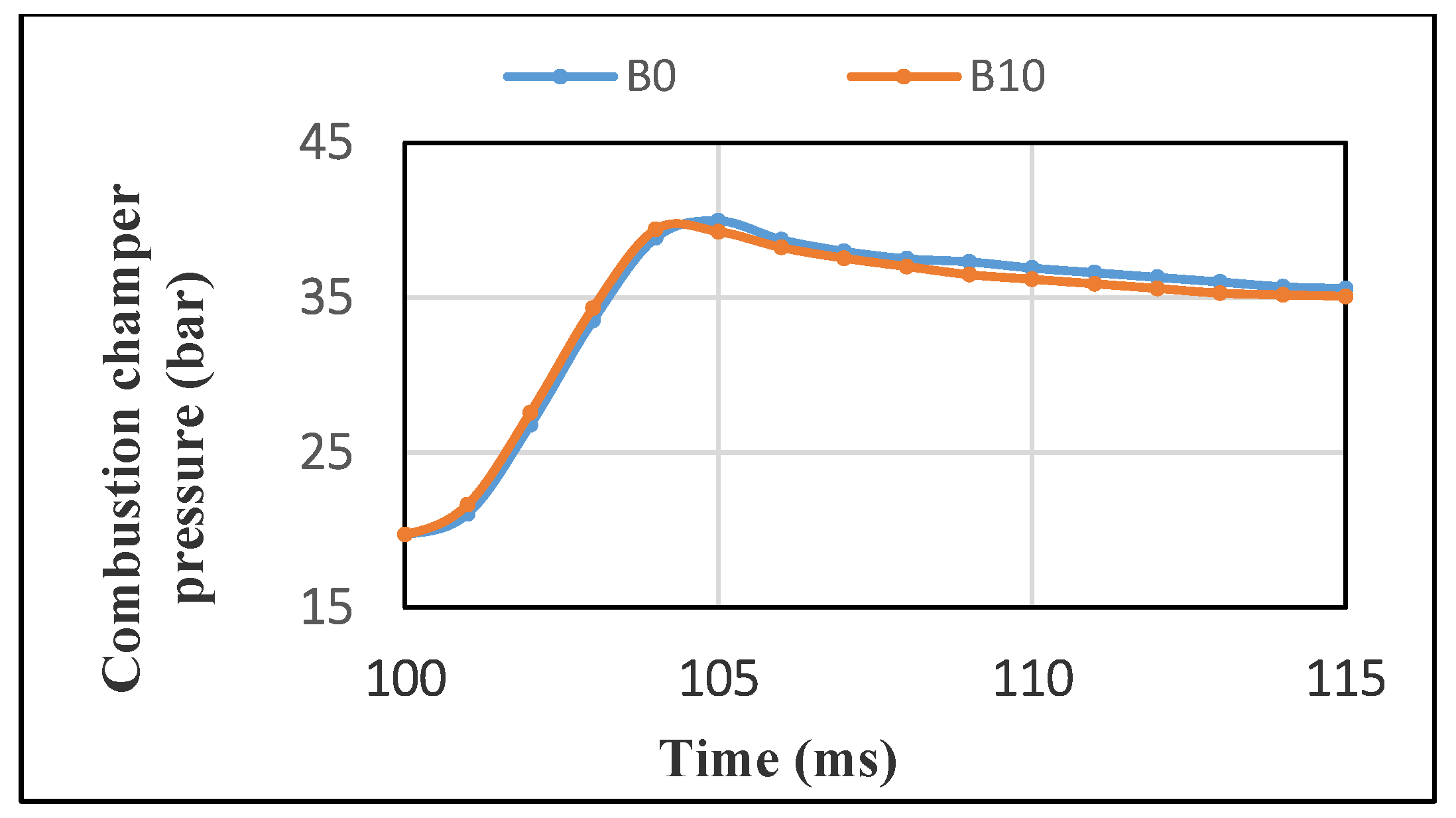
3.2.2. Pressure in the CVCC Combustion Chamber
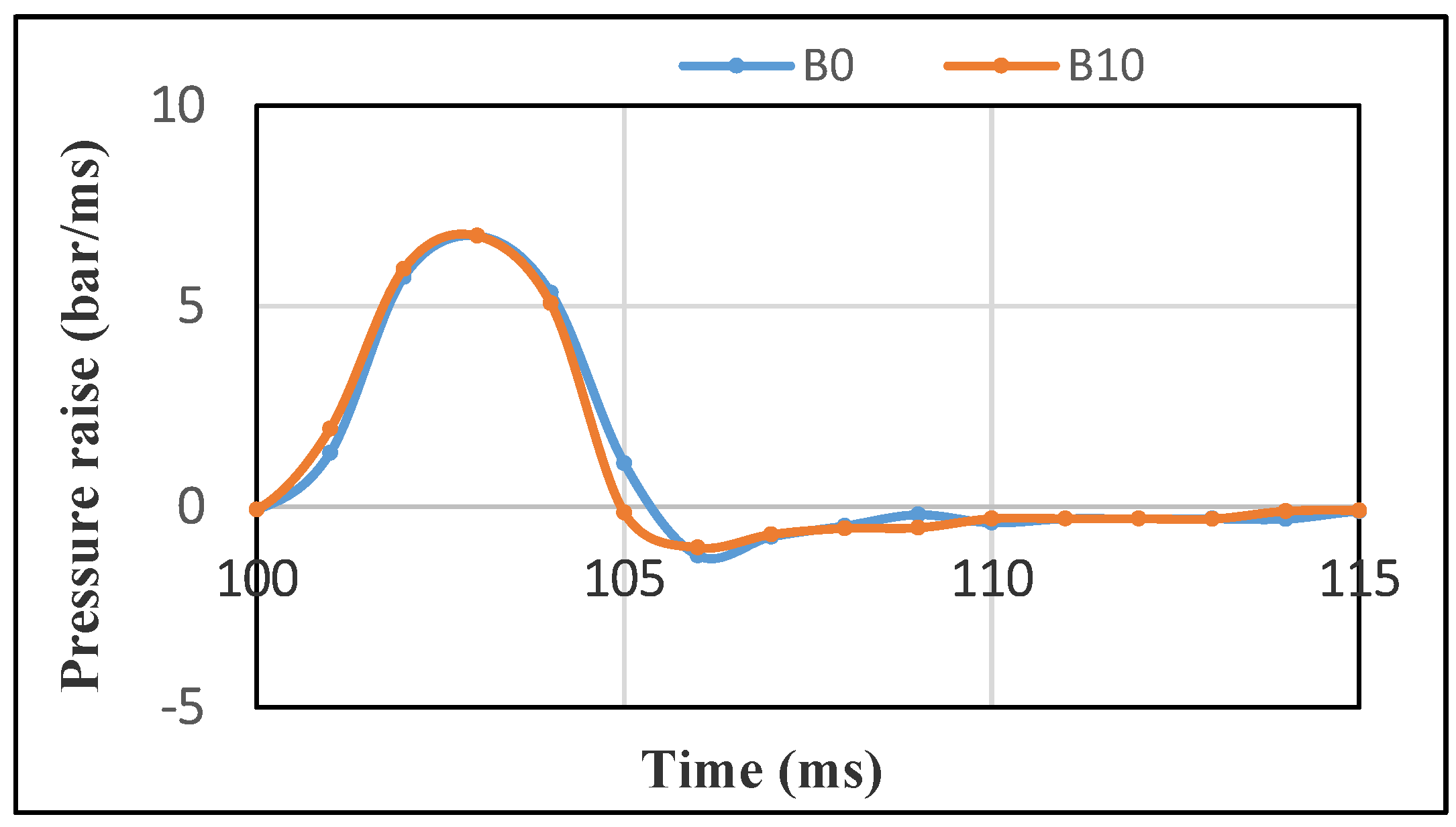
3.2.3. Combustion Pressure Raise
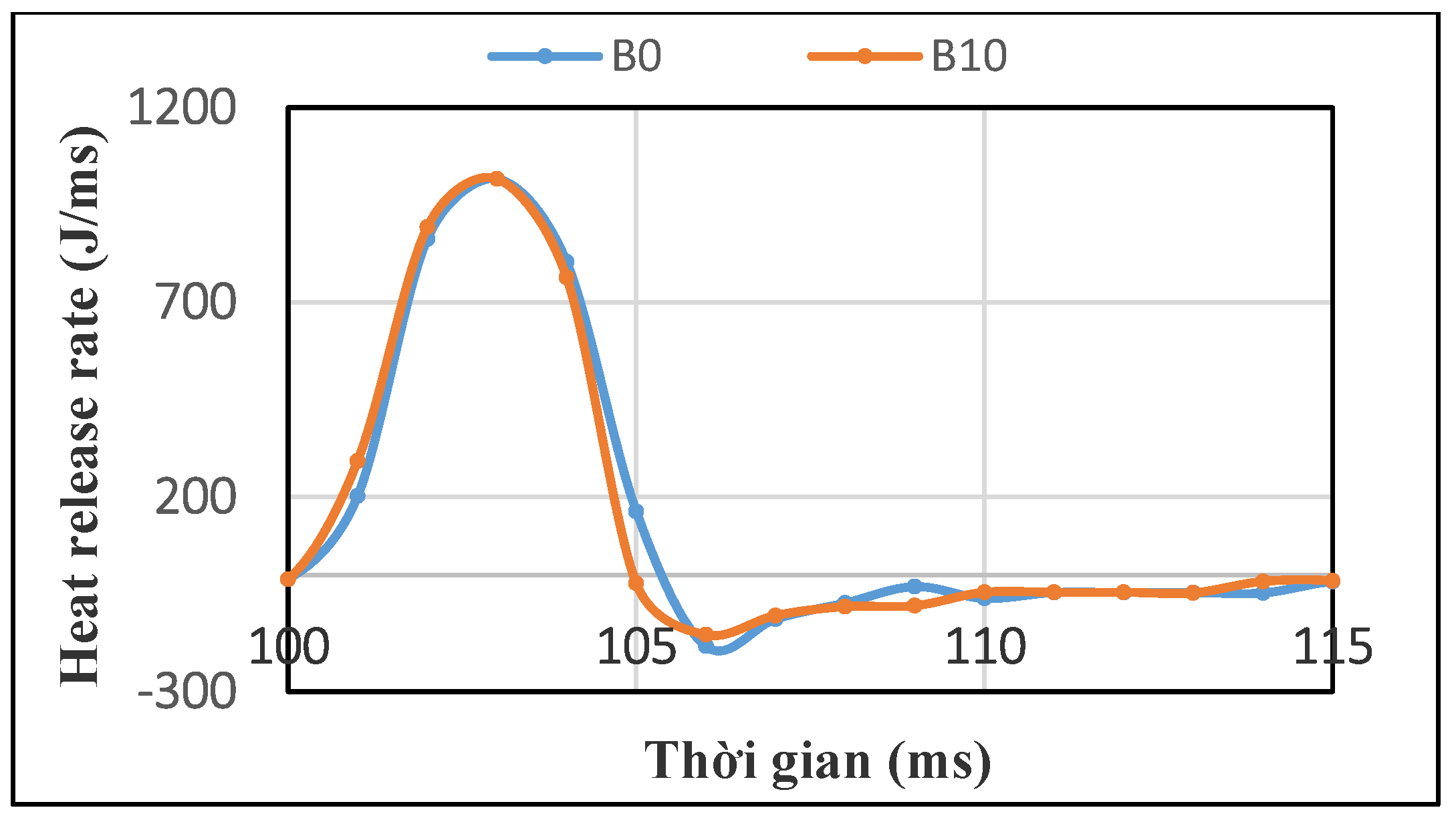
3.2.4. Heat Release Rate
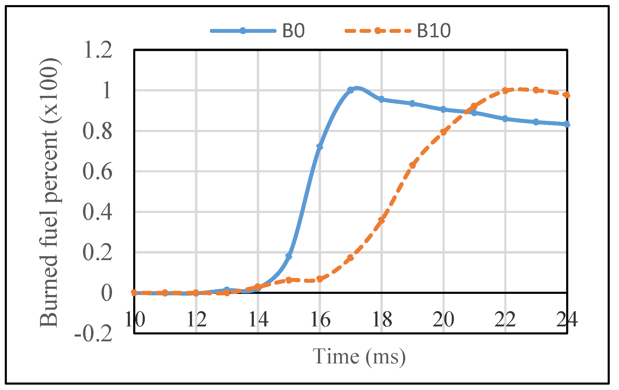
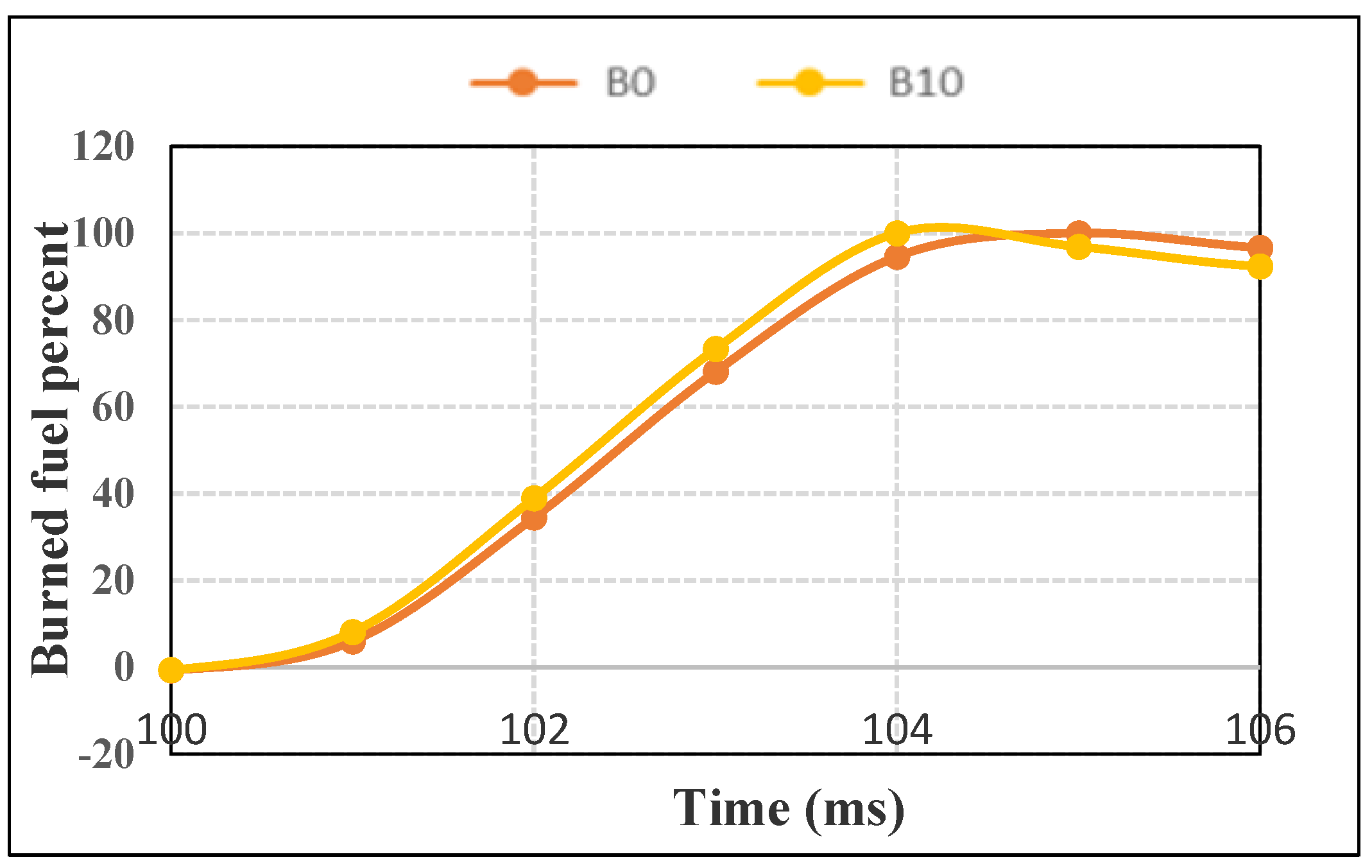
3.2.5. Percent of Burned Fuel
4. Conclusions
Author Contributions
Funding
Institutional Review Board Statement
Informed Consent Statement
Data Availability Statement
Conflicts of Interest
References
- Sahoo, B.B.; Saha, U.K.; Sahoo, N. Theoretical performance limits of a syngas-diesel fueled compression ignition engine from second law analysis. Energy 2011, 36, 760–769. [Google Scholar] [CrossRef]
- Wagemakers, A.M.L.M.; Leermakers, C.A.J. Review on the Effects of Dual-Fuel Operation, Using Diesel and Gaseous Fuels, on Emissions and Performance. SAE Int. J. Engines 2012. [Google Scholar] [CrossRef] [Green Version]
- Deng, Y.; Liu, H.; Zhao, X.; E, J.; Chen, J. Effects of cold start control strategy on cold start performance of the diesel engine based on a comprehensive preheat diesel engine model. Appl. Energy 2018, 210, 279–287. [Google Scholar] [CrossRef]
- E, J.; Zang, Z.; Tu, Z.; Zuo, W.; Hu, W.; Han, D.; Jin, Y. Effect analysis on flow and boiling heat transfer performance of cooling water-jacket of bearing in the gasoline engine turbocharger. Appl. Therm. Eng. 2018, 130, 754–766. [Google Scholar] [CrossRef]
- Zhang, B.; E, J.; Gong, J.; Yuan, W.; Zuo, W.; Li, Y.; Fu, J. Multidisciplinary design optimization of the diesel particulate filter in the composite regeneration process. Appl. Energy 2016, 181, 14–28. [Google Scholar] [CrossRef]
- E, J.; Zuo, W.; Gao, J.; Peng, Q.; Zhang, Z.; Pham, M. Effect analysis on pressure drop of the continuous regeneration-diesel particulate filter based on NO2 assisted regeneration. Appl. Therm. Eng. 2016, 100, 356–366. [Google Scholar] [CrossRef]
- E, J.; Han, D.; Deng, Y.; Zuo, W.; Qian, C.; Wu, G.; Peng, Q.; Zhang, Z. Performance enhancement of a baffle-cut heat exchanger of exhaust gas recirculation. Appl. Therm. Eng. 2018, 134, 86–94. [Google Scholar] [CrossRef]
- Dincer, I.; Rosen, M.A. Thermodynamic aspects of renewables and sustainable development. Renew. Sustain. Energy Rev. 2005, 9, 169–189. [Google Scholar] [CrossRef]
- Bundschuh, J.; Chen, G.; Yusaf, T.; Chen, S.; Yan, J. Sustainable energy and climate protection solutions in agriculture. Appl. Energy 2014, 114, 735–736. [Google Scholar] [CrossRef]
- Wen, Z.; Yu, X.; Tu, S.T.; Yan, J.; Dahlquist, E. Synthesis of biodiesel from vegetable oil with methanol catalyzed by Li-doped magnesium oxide catalysts. Appl. Energy 2010, 87, 743–748. [Google Scholar] [CrossRef]
- Cynthia, O.B.; Lee, K.T.; Lim, J.K. Comparative exergy analyses of Jatropha curcas oil extraction methods: Solvent and mechanical extraction processes. Energy Convers. Manag. 2012, 55, 164–171. [Google Scholar]
- Lim, S.; Lee, K.T. Investigation of impurity tolerance and thermal stability for biodiesel production from Jatropha curcas L. seeds using supercritical reactive extraction. Energy 2014, 68, 71–79. [Google Scholar] [CrossRef]
- Aghbashlo, M.; Demirbas, A. Biodiesel: Hopes and dreads. Biofuel Res. J. 2016, 3, 379. [Google Scholar] [CrossRef] [Green Version]
- Tabatabaei, M.; Karimi, K.; Horvath, I.S.; Kumar, R. Recent trends in biodiesel production. Biofuel Res. J. 2015, 2, 258–267. [Google Scholar] [CrossRef]
- Sharma, Y.C.; Singh, B.; Madhu, D.; Liu, Y.; Yaakob, Z. Fast synthesis of high quality biodiesel from ‘waste fish oil’ by single step transesterification. Biofuel Res. J. 2014, 1, 78–80. [Google Scholar] [CrossRef]
- Kannan, G.R.; Anand, R. Effect of injection pressure and injection timing on DI diesel engine fuelled with biodiesel from waste cooking oil. Biomass Bioenergy 2012, 46, 343–352. [Google Scholar] [CrossRef]
- Hoekman, S.K.; Robbins, C. Review of the effects of biodiesel on NOx emissions. Fuel Process. Technol. 2012, 96, 237–249. [Google Scholar] [CrossRef]
- Enweremadu, C.C.; Rutto, H.L. Combustion, emission and engine performance characteristics of used cooking oil biodieseldA review. Renew. Sustain. Energy Rev. 2010, 14, 2863–2873. [Google Scholar] [CrossRef]
- Khalife, E.; Tabatabaei, M.; Demirbas, A.; Aghbashlo, M. Impacts of additives on performance and emission characteristics of diesel engines during steady state operation. Prog. Energy Combust. Sci. 2017, 59, 32–78. [Google Scholar] [CrossRef]
- Dias, J.M.; Alvim-Ferraz, M.C.M.; Almeida, M.F.; Díaz, J.D.M.; Polo, M.S.; Utrilla, J.R. Biodiesel production using calcium manganese oxide as catalyst and different raw materials. Energy Convers. Manag. 2013, 65, 647–653. [Google Scholar] [CrossRef]
- Rattanapoltee, P.; Kaewkannetra, P. Cultivation of microalga, Chlorella vulgaris under different autoeheteroemixo trophic growths as a raw material during biodiesel production and cost evaluation. Energy 2014, 78, 4–8. [Google Scholar] [CrossRef]
- Piastrellini, R.; Arena, A.P.; Civit, B. Energy life-cycle analysis of soybean biodiesel: Effects of tillage and water management. Energy 2017, 126, 13–20. [Google Scholar] [CrossRef]
- Kuss, V.V.; Kuss, A.V.; Rosa, R.G.D.; Aranda, D.A.G.; Cruz, Y.R. Potential of biodiesel production from palm oil at Brazilian Amazon. Renew. Sustain. Energy Rev. 2015, 50, 1013–1020. [Google Scholar] [CrossRef]
- Sinha, S.; Agarwal, A.S. Combustion Characteristics of Rice Bran Oil Derived Biodiesel in a Transportation Diesel Engine. SAE Pap. 2005, 26, 354. [Google Scholar]
- Senatore, A.; Cardone, M.; Rocco, V.; Prati, M.V. A Comparative Analysis of Combustion Process in D. I. Diesel Engine Fueled with Biodiesel and Diesel Fuel. Trans. SAE 2000. [Google Scholar] [CrossRef]
- van Gerpen, J.H.; Hammond, E.G.; Yu, L.; Monyem, A. Determining the influence of contaminants on Biodiesel Properties. SAE Pap. 1997, 971685. [Google Scholar] [CrossRef] [Green Version]
- Hajialimohammadi, A.; Ahmadisoleymani, S.; Abdullah, A.; Asgari, O.; Rezai, F. Design And Manufacturing of A Constant Volume Test Combustion Chamber For Jet And Flame Visualization of CNG Direct Injection. Appl. Mech. Mater. 2012, 217–219, 2539–2545. [Google Scholar] [CrossRef]
- Srichai, P.; Chareonphonphanich, C.; Karin, P.; Chollacoop, N. Design Concept of Biodiesel Direct Injection Constant Volume Combustion Chamber. In Proceedings of the 3rd TSME International Conference on Mechanical Engineering, Chiang Rai, Thailand, 24–27 October 2012. [Google Scholar]
- Jung, J.; Park, S.; Bae, C. Combustion characteristics of gasoline and n-butane under lean stratified mixture conditions in a spray-guided direct injection spark ignition engine. Fuel 2017, 187, 146–158. [Google Scholar] [CrossRef]
- Sateesh, K.A.; Yaliwal, V.S.; Soudagar, M.E.M.; Banapurmath, N.R.; Fayaz, H.; Safaei, M.R.; Elfasakhany, A.; El-Seesy, A.I. Utilization of biodiesel/Al2O3 nanoparticles for combustion behavior enhancement of a diesel engine operated on dual fuel mode. J. Therm. Anal. 2021, 1–15. [Google Scholar] [CrossRef]
- Soudagar, M.; Khan, H.; Khan, T.; Razzaq, L.; Asif, T.; Mujtaba, M.; Hussain, A.; Farooq, M.; Ahmed, W.; Shahapurkar, K.; et al. Experimental Analysis of Engine Performance and Exhaust Pollutant on a Single-Cylinder Diesel Engine Operated Using Moringa Oleifera Biodiesel. Appl. Sci. 2021, 11, 7071. [Google Scholar] [CrossRef]
- Soudagar, M.E.M.; Afzal, A.; Safaei, M.R.; Manokar, A.M. Investigation on the effect of cottonseed oil blended with different percentages of octanol and suspended MWCNT nanoparticles on diesel engine characteristics. J. Therm. Anal. Calorim. 2021, 147, 525–542. [Google Scholar] [CrossRef]
- Marasri, S.; Ewphun, P.-P.; Srichai, P. Experimental Investigation on Combustion Characteristics of Hydrotreated Vegetable Oil (HVO)-Diesel Blended Fuels in Constant Volume Combustion Chamber (CVCC). In Proceedings of the JSAE Annual Congress (Spring), Yokohama, Japan, 18–26 May 2017. [Google Scholar]
- Kitamura, Y.; Mohammadi, A.; Ishiyama, T.; Shioji, M. Fundamental Investigation of NOx Formation in Diesel Combustion Under Supercharged and EGR Conditions. SAE Int. 2005, 13. [Google Scholar] [CrossRef]
- Bendu, H.; Sivalingam, M. Experimental investigation on the effect of charge temperature on ethanol fueled HCCI combustion engine. J. Mech. Sci. Technol. Pap. 2016, 30, 4791–4799. [Google Scholar] [CrossRef]
- Noguchi, M.; Tanaka, Y.; Tanaka, T.; Takeuchi, Y. A study on gasoline engine combustion by observation on intermediate reactive products during combustion. SAE Pap. 1979, 2816–2828. [Google Scholar] [CrossRef]
- Herbinet, O.; Pitz, W.J.; Westbrook, C.K. Detailed chemical kinetic oxidation mechanism for a biodiesel surrogate. Combust. Flame 2008, 154, 507–528. [Google Scholar] [CrossRef] [Green Version]
- Szybist, J.; Song, J.; Alam, M.; Boehman, A.L. Biodiesel combustion, emissions and emission control. Fuel Process. Technol. 2007, 88, 679–691. [Google Scholar] [CrossRef]


| Parameter | Values | Unit |
|---|---|---|
| Outer diameter | 200 | mm |
| Inner diameter | 80 | mm |
| Cylinder length | 90 | mm |
| Supply air maximum pressure | 80 | bar |
| Common rail fuel supply system | 200 | Mpa |
| Fame | Fame Composition (%) |
|---|---|
| C16H32O2 | 28.09 |
| C18H32O2 | 18.02 |
| C18H34O2 | 43.47 |
| C18H36O2 | 9.53 |
| Other | 0.89 |
| Property | Unit | B0 | B10 |
|---|---|---|---|
| Heating value | MJ/kg | 42.76 | 42.39 |
| Cetane No | - | 49 | 48 |
| Density | kg/m3 | 838 | 847 |
| Kinematic viscosity at 40 °C | mm2/s | 3.22 | 3.61 |
| Flash point | °C | 67 | 75 |
| Sulfur | ppm | 428 | 431 |
| Water content | ppm | 62 | 83 |
| Stable working pressure range | 0 ÷ 25 bar |
| Error | ±0.3% |
| Stable working temperature | −40 ÷ 400 °C |
| Sensitivity | 16 pC bar |
| Parameter | Condition |
|---|---|
| Fuel | Diesel, bio-diesel 10% |
| Nozzle diameter | 0.14 (mm) |
| Spray time | 3 (ms) |
| Spray pressure | 150 MPa |
| Environment temperature | 297 K |
| Oxygen concentration | 20% |
| Number of experiments | 10 |
Publisher’s Note: MDPI stays neutral with regard to jurisdictional claims in published maps and institutional affiliations. |
© 2022 by the authors. Licensee MDPI, Basel, Switzerland. This article is an open access article distributed under the terms and conditions of the Creative Commons Attribution (CC BY) license (https://creativecommons.org/licenses/by/4.0/).
Share and Cite
Nghia, N.T.; Truong, N.P.; Khoa, N.X.; Tuan, L.A.; Tuan, N.V. A Comparison in Combustion Characteristics in a CVCC with Biodiesel Blends. Energies 2022, 15, 1017. https://doi.org/10.3390/en15031017
Nghia NT, Truong NP, Khoa NX, Tuan LA, Tuan NV. A Comparison in Combustion Characteristics in a CVCC with Biodiesel Blends. Energies. 2022; 15(3):1017. https://doi.org/10.3390/en15031017
Chicago/Turabian StyleNghia, Nguyen Tuan, Nguyen Phi Truong, Nguyen Xuan Khoa, Le Anh Tuan, and Nguyen Van Tuan. 2022. "A Comparison in Combustion Characteristics in a CVCC with Biodiesel Blends" Energies 15, no. 3: 1017. https://doi.org/10.3390/en15031017
APA StyleNghia, N. T., Truong, N. P., Khoa, N. X., Tuan, L. A., & Tuan, N. V. (2022). A Comparison in Combustion Characteristics in a CVCC with Biodiesel Blends. Energies, 15(3), 1017. https://doi.org/10.3390/en15031017