Article

Latent Thermal Energy Storage Application in a Residential Building at a Mediterranean Climate

1
ESTSetúbal, CINEA, Polytechnic Institute of Setúbal (IPS), 2910-761 Setúbal, Portugal
2
Energy and Environmental Research Laboratory, General (Core) Department, National and Kapodistrian University of Athens, Psachna Campus, 34400 Evia, Greece
3
Centre for Renewable Energy Sources and Saving (CRES), Marathonos 19th Km, 19009 Pikermi, Greece
4
Institute for Power Systems Technology and Power Mechatronics, Ruhr-University, 44801 Bochum, Germany
5
Z&X Mechanical Installations Limited 12 Agapinoros Str, Paphos 8049, Cyprus
*
Author to whom correspondence should be addressed.
Energies 2022, 15(3), 1008; https://doi.org/10.3390/en15031008
Submission received: 10 December 2021 / Revised: 24 January 2022 / Accepted: 27 January 2022 / Published: 29 January 2022
(This article belongs to the Special Issue Thermal Storage Technologies)

Abstract

:
An innovative thermal energy storage system (TESSe2b) was retrofitted in a residential building in Cyprus with a typical Mediterranean climate. The system comprises flat-plate solar collectors, thermal energy storage tanks filled with organic phase change material, a geothermal installation consisting of borehole heat exchangers with and without phase change material and a ground source heat pump, an advanced self-learning control system, backup devices and several other auxiliary components. The thermal energy storage tanks cover the building’s needs at certain temperature ranges (10–17 °C for cooling, 38–45 °C for heating and 50–60 °C for domestic hot water). A performance evaluation was conducted by comparing the TESSe2b system with the existing conventional heating and cooling system. The systems were simulated using commercial software, and the performance of the systems and the building’s energy needs were calculated. Based on the energy quantities, an economic analysis followed. The equivalent annual primary energy consumption with the conventional system resulted in being 43335 kWh, while for the storage system, it was only 8398 kWh. The payback period for the storage system was calculated to be equal to 9.76 years. The operation of the installed storage system provided data for calculations of the seasonal performance factor and storage performance. The seasonal performance factor values were very high during June, July and August, since the TESSe2b system works very efficiently in cooling mode due to the very high temperatures that dominate in Cyprus. The measured stored thermal energy for cooling, heating and domestic hot water resulted in being 14.5, 21.9 and 6.2 kWh, respectively. Moreover, the total volume of the phase change material thermal energy storage tanks for heating and domestic hot water was calculated to be roughly several times smaller than the volume of a tank with water as a storage medium.

1. Introduction

Climate change necessitates solutions for the reduction of buildings’ thermal energy needs. Along these lines, the European Commission recently revised the Energy Efficiency Directive together with other EU energy and climate rules to ensure that the new 2030 target of reducing greenhouse gas emissions by at least 55% (compared with 1990) can be met [1]. To achieve those goals, rapid uptake of renewable sources is required throughout all kinds of energy use. Solar energy has been utilized in residential cooling and heating and domestic hot water (DHW) production systems [2,3], however, it is a time-dependent energy resource. To overcome the issue arising in synchronizing energy demand and supply, thermal energy storage is required to store energy for use when sunshine is not available [4,5]. Thermal energy storage is a technology that has gained popularity over recent years [6,7,8] as it can help to integrate high shares of renewable energy in power generation, industry and buildings. It is a key element of the energy transition measures for all countries in the post-COVID period. Shallow geothermal energy is a sustainable energy resource for space heating and cooling in residential buildings. It can work by coupling a heat pump with the ground by means of borehole heat exchangers (BHEs), which can be either vertical (boreholes) or horizontal. The weak point in BHEs is that heat transfer in the ground is mainly conductive with low thermal diffusivity, which leads to a much slower ground thermal response than the heat pump’s requirements, resulting in a lower coefficient of performance for ground source heat pumps (GSHPs). The effectiveness of BHEs can be improved by mixing PCMs directly with backfill material [9,10,11].
In light of the above, in the TESSe2b project [12] the potential for a thermal energy storage system for energy-efficient buildings was investigated. This is an integrated solution for residential building energy storage using solar and geothermal energy, with the purpose of correcting the mismatch that often occurs between the supply and the demand of energy in residential buildings. The storage of thermal energy was accomplished with the use of PCMs. TES tanks have been designed in a compact and modular manner and can be scaled according to the residential energy needs. TES tanks store energy at three different levels: (1) for residential space cooling (Cooling Thermal Energy Storage (CTES) tanks, (2) for residential space heating (heating thermal energy storage (HTES) tanks) and for domestic hot water (DHW) needs. Thermal storage at three different temperature levels in domestic buildings is experimentally investigated for first time, according to the authors’ knowledge. To increase the efficiency of the TESSe2b solution, BHEs enhanced with PCM are integrated, which is also a novel experimental investigation. An advanced control is implemented, having a key role for the optimal charge/discharge cycles of the TESSe2b project and the overall efficiency by system-wide optimization of the components and their operation. Following the TESSe2b system’s development on a small scale and then on the actual scale under laboratory conditions [13,14,15] it was installed in three demo residential buildings in three European countries with different climates, namely Austria, Cyprus and Spain. Such a study in three different climates has never been conducted before.
The scope of this paper is to present the results from the implementation of the system in one of the TESSe2b demo residential buildings in a Mediterranean climate in Cyprus’s Paphos region and evaluate its technical and economical performance. The climate of Cyprus is indicative of the hot climate that exists in Europe and can be considered an indicator for cooling needs. According to the Köppen climate classification, Cyprus, including the Paphos region, belongs to the Csa type (Mediterranean climate). Using appropriate software, the theoretical energy needs of the building are calculated and analyzed, and using the real data collected from the implementation of the TESSe2b system on the building, the critical quantities are calculated. It was evaluated that the TESSe2b system had lower equivalent primary energy for heating, cooling and DHW when compared with a conventional system that is used in Cyprus, consisting of a boiler and burner using heat oil (heating), split units (cooling) and solar supported by electric heating element DHW. Furthermore, the thermal energy storage supported a 44.8% shift of the heating needs from day to night and a 30.3% shift in the cooling needs.

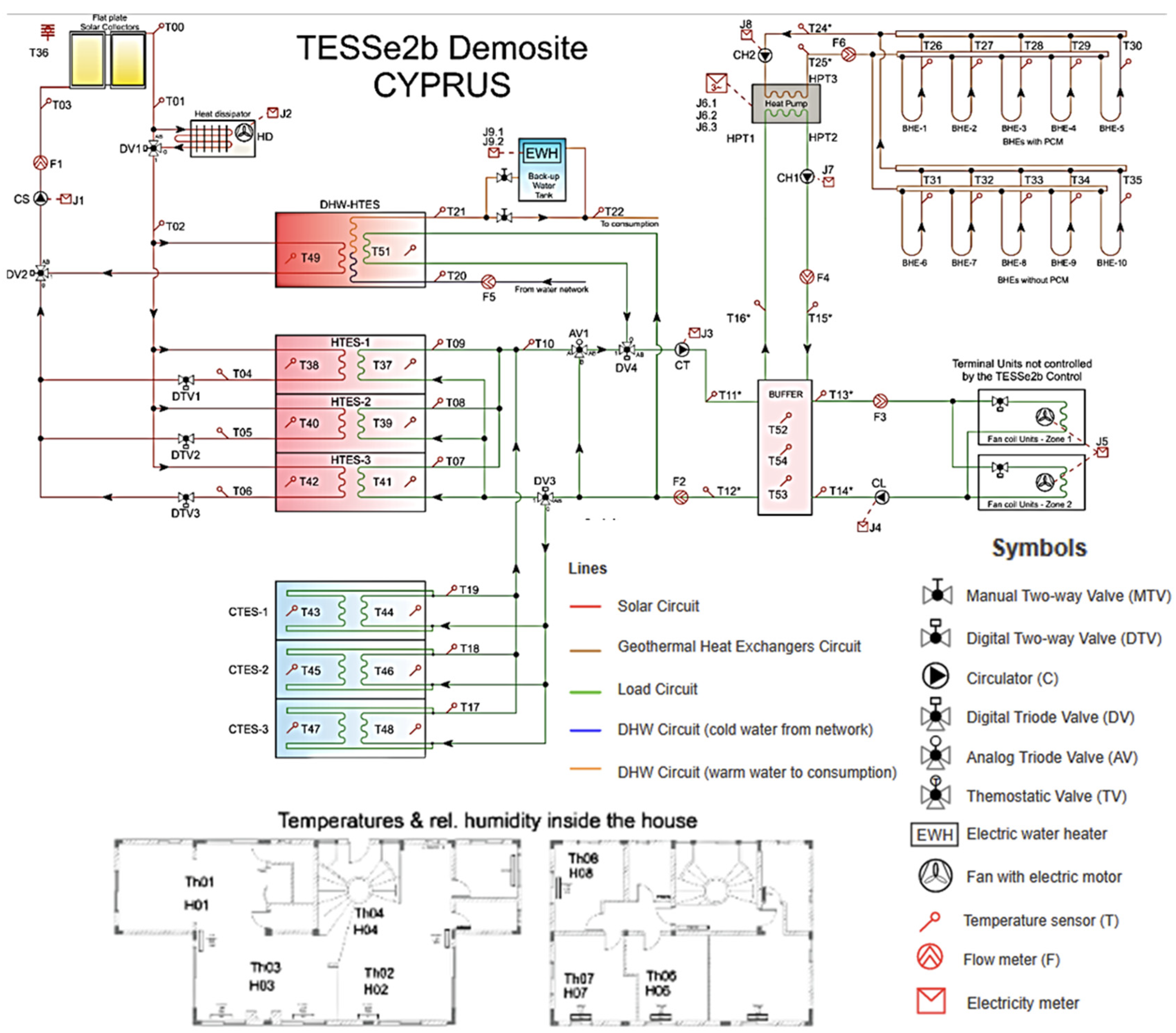
2. The TESSe2b Approach

In Figure 1, the TESSe2b hydraulic scheme is shown as it was customized for the demo building in Cyprus.
The system consists of six basic components: solar thermal collectors, one geothermal heat pump in which the low-temperature heat source is a vertical ground heat exchanger, hot and cold TES tanks with PCM (three tanks for cooling and three tanks for heating), a DHW tank also with PCM and a building with low temperature heat receivers, such as underfloor heating or fan coils for the building in Cyprus. Hot TES tanks and TES DHW tanks are coupled to BHEs enhanced with paraffin PCM (five BHEs with PCM and five BHEs without). The TES cold tanks are coupled with a heat pump. The solution is controlled by an advanced self-learning control system [17].
Solar radiation heats the solar collector fluid, and the thermal energy stored in it is then transferred to the PCM-based thermal energy storage. In order to limit the temperature during intense solar radiation conditions or when the thermal energy storage has reached its maximum capacity and the energy cannot be extracted from the fluid, a heat dissipator connected to the solar collector fluid cycle is used. The energy is thus dissipated to the environment. Using the thermal energy in the HTES and DHW tanks, heating units can be supplied with water at an adequate temperature, and domestic hot water is available for the building residents. In summer conditions with high solar radiation intensities and low heating energy demand, the entire house can be supplied using only the stored energy from the solar collectors. In winter, however, solar radiation intensity decreases, and the demand for heating energy is high. At that time, a highly efficient heat pump is used to extract energy from the ground and transfer it to the thermal storage for DHW or directly to the building to provide heating. It is used to compensate for the gap between the energy supply from the solar collectors and the residential energy demand at the expense of electrical energy drawn from the grid. The goal of the operation management is to minimize the use of the heat pump and the related energy costs in order to ensure a cost-efficient and environmentally friendly operation of the system.
The major TESSe2b components are described in brief in the following.
TES tanks: The TESSe2b TES tanks were designed in a compact and modular manner for easy integration into the buildings. Each tank stores energy at a temperature range of 38–45 °C for heating, 10–17 °C for cooling and 50–60 °C for DHW. Their design was carried out according to European standards using finite element analysis (FEA) [18]. TES tanks are made of polypropylene (PP), and they are covered internally by an epoxy-based product to prevent surface cracking of the PP caused by hydraulic forces of the absorbed PCM during its change of phase, as PP is affected after being in warm contact with the organic PCM tested. The epoxy product was tested in the lab, where no effect occurred on the hardness properties and mass uptake of the samples using it as coating [19]. They are reinforced by five horizontal ribs and three steel bars (Figure 2). Inside each tank, there is a fin and tube heat exchanger (HE), which is designed properly to achieve the required heat transfer rate between the PCM and the heat transfer fluid (HTF) during the TES tank’s operation (charging/discharging processes). The tank’s modular design enables system designers to match the total energy storage capacity of the system to each building, selecting the appropriate number of tanks. The internal volume of each tank is approximately 160 L.
Solar collectors: Typical flat plate solar collectors were used.
Geothermal installation: This comprises the geothermal BHEs and the GSHP. It is used for the storage of thermal energy, thus supporting the system in order to increase its performance in the heating and cooling mode. During operation of the heat pump in heating mode, the temperature of the heat carrier fluid within the BHE will decrease, and during cooling, it will increase. Adding PCMs into the boreholes is regarded as an effective means to store thermal energy in the BHEs and improves the performance of GSHP systems. The thermal energy stored in the PCMs will smooth the ground thermal wave generated by the GSHP operation and enhance the seasonal performance factor (SPF) of the system. Depending on the PCM phase change temperature, this can be applied to the heating or cooling mode. The PCMs used in the BHE are paraffins, and the selected phase change temperature takes into account the ground temperature at each location of the demo sites and the most critical mode of operation: heating or cooling. For Cyprus, the critical mode is cooling, and the phase change temperature considered was 28 °C.
Smart Control System: The control system developed in the TESSe2b project ensures the cooperation of all components in an efficient way. The basic operations that the TESSe2b system is performing are the heating, cooling and dehumidification of a building using solar and geothermal energy, the provision of domestic hot water, the storage of solar and geothermal energy for heating and cooling in PCM tanks and the safe operation and protection of the system components.
The control system coordinates these components in order to efficiently execute the main functions of the system. The TESSe2b controller is a central controller that is responsible for providing DHW and the necessary thermal power to the heating and cooling devices of the building. The TESSe2b controller monitors the inlet and outlet temperature of the heating and cooling devices, and it regulates the flow and temperature of the HTF in the load loop in order to ensure that the appropriate amount of energy is being efficiently supplied to the house. The controller ensures that the desired DHW temperature is provided at all times, regardless of the consumption. The controller also has the task of sustaining the operating temperatures of hot and cold PCM tanks within the safety limits of the PCM material in order to extend their lifetime and for performing other safety functions, such as safe operation in case of a component failure or during extreme weather conditions. The control system is managed based on the input of an array of sensors and actuators that automatically changes the system’s mode of operation according to the needs of the building. The TESSe2b controller is independent of the building installation. The temperature control of individual rooms or zones is performed by decentralized control devices and thermostats, which are not an integral part of the TESSe2b system as they depend on the type of heating and cooling devices of the building. This structure allows the installation of the TESSe2b system not only in new residential buildings but also in existing buildings without the need for replacing the heating and cooling devices.

3. TESSe2b System Design for Cyprus Demo Site
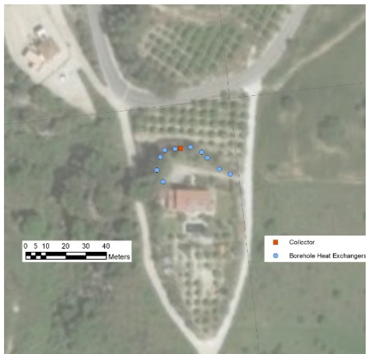
3.1. About the Area

The house is located in Mιliou village, 35 km north of the town of Pafos, where the climate is typically Mediterranean [20]. The location of the demo site is 34°55′58.7″ N, 32°27′57.4″ E, as defined by the Google Earth application. The village is at a medium altitude of 420 m from sea level, and the temperature fluctuates from 34 °C in July to 4 °C in January. The daily span in temperature can reach 16 °C. The sunshine over the area is relatively high, ranging from 5.5 h in winter to 11.5 h in summer, and the annual solar irradiation is about 1850 kWh/m2.
The average annual rainfall is 470 mm, mainly during winter and spring. In the eastern Mediterranean region, general winds are mostly mild to moderate to the west or southwest in winter and north or northwest in summer. Very strong winds (over 34 knots) are rare. The subsoil of Miliou is mainly limestone and chalks. Weather station equipment was installed in the building in order to provide weather data.

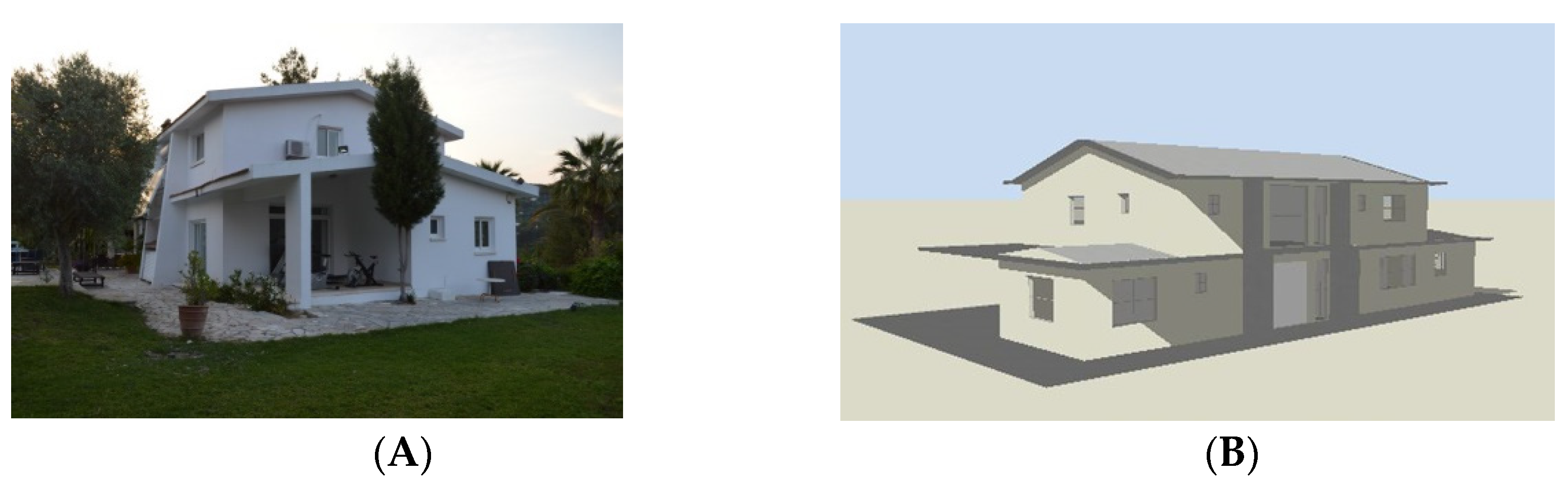
3.2. Description of the Building and Its Needs

The building use is residential with a surface area of 221 m2, and it is located on a 3500-m2 plot. Figure 3A shows the photo of the building, and Figure 3B shows the geometric model of the Design Builder (DB) software [21]. There is also a small basement, which has been turned into an engine room. The building is 30 years old, and it is in good condition with brick plastered walls and roof tiling. The underground area is rich in geothermal energy because of underground flowing water masses. Heating needs are covered by oil-fired boilers, burners and radiators, while cooling needs are covered by split units. The existing DWH system consists of a solar system with 2 flat plate collectors and a storage cylinder on the roof with a 4-kW electrical element, and it is also served by the oil-fired boiler.
For the dimensioning of the TESSe2b system in order to cover heating, cooling and DHW needs and the evaluation of its performance, the building energy requirements were obtained using Design Builder (DB) software [21]. The climatic data of Paphos, Cyprus were used, which were available in Design Builder, and they were validated with the measurements implemented by the weather station installed in the demo site.
In order to implement the building simulations and conclude the annual needs shown in Table 1, the following assumptions were considered:
  • Heating season: November to mid-April
  • Cooling season: mid-April to September
  • Indoor temperatures: 20 °C (heating); 25 °C (cooling);
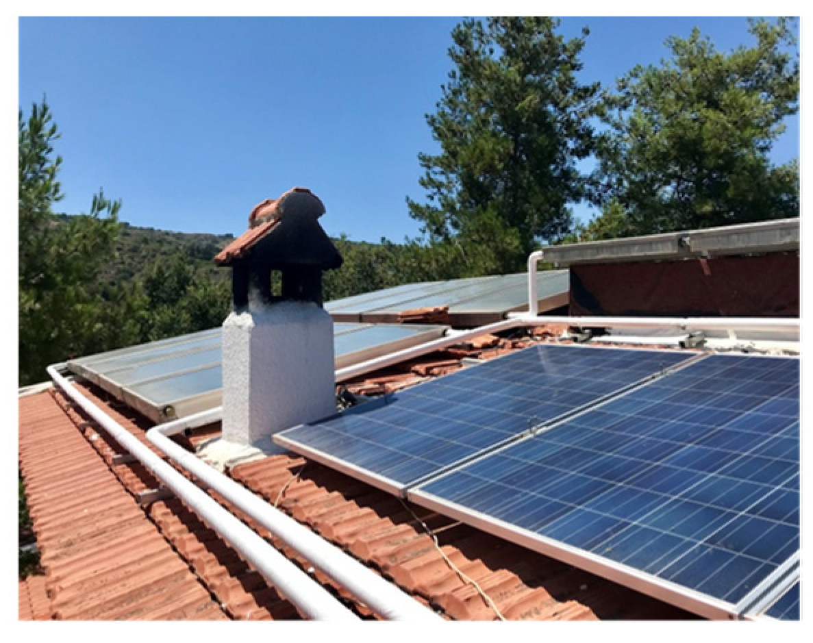
  • Solar Collectors: Flat Panel
  • DWH: 4 persons, 160 L per day; 45 °C
  • Load Terminal Units for heating and cooling: fan-coils;
  • Utilization Schedules and heating or cooling: depending of the room;
  • Building total floor area: 221 m2
  • There is no thermal insulation in the thermal envelope.

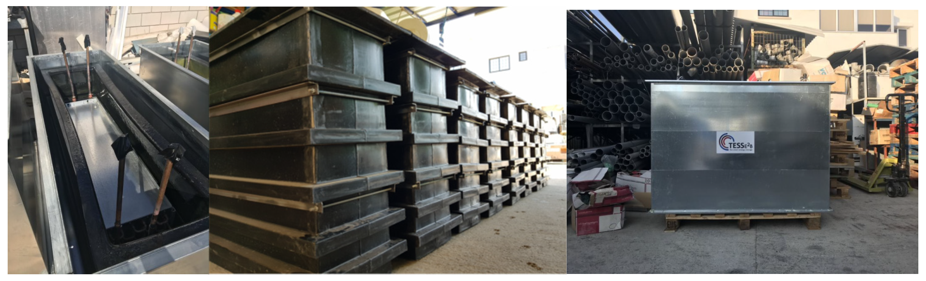
3.3. TESSe2b Implementation

The TESSe2b system with PCM storage was designed and installed in order to maximize the solar fraction due to the PCM’s large amount of latent heat in comparison with the energy storage based in sensible heat using water volume storage.
Solar system: The solar system comprised 10 typical flat plate solar collectors with selective absorber, which were installed on the residence’s roof (Figure 4). Each solar collector was 2 m × 1 m in size (1.83 m2 active area). A heat dissipator was also used (electrical power: 0.5 kW).
TES tanks: Based on the design calculations and considering the house characteristics and climate of the area, it was concluded that the total storage volume was 3 HTES tanks, 3 CTES tanks and 1 DHW tank which were 0.16 m3 each with a total volume (based on the HE level) of 1.12 m3. For heating, the tanks may have needed the heat pump’s support to cover the building needs at some peak hours per year. For cooling, the CTES tanks were able to cover all cooling needs in terms of capacity, even during the peak hours.
Geothermal installation: This comprised a GSHP with a total cooling capacity of 18.6 KW, heating capacity of 26.3 kW and 10 BHEs. Half of the boreholes (5) had an extra U-tube inserted. which was filled with PCM. Liquid A28 PCM was poured into the preinstalled pipework in the BHEs. The heat pump was in cooling mode (heat rejection) so as to avoid solidification of the PCM while traveling down the pipework. The depth was 100 m for all BHEs, and the distance between each BHE was 6 m. All BHEs were drilled at the north and northwest sides of the pilot building area (Figure 5). The wet drilling method was used, and the BHEs without PCM were drilled with an 8″ (203 mm) casing diameter and a bit diameter of 6″ (152 mm), while the BHEs with PCM had a 10″ (254 mm) casing diameter and a bit diameter of 8″ (203 mm). The casing depth was 6 m for all boreholes. A single 40 mm × 3.7 mm U-tube was built in for the circulation of the HTF in each BHE. The grouting was performed with a mortar mixing pump until the grout appeared on the surface. The grouting pipes were set at a depth of 90 m. The grout used was Calidutherm, a thermally enhanced grout especially for BHEs distributed by the company Terra Calidus (Germany) with a thermal conductivity of 2 W/m·K to ensure optimal heat transfer between the ground and BHE.
Back-up system: A 300-L DWH backup system was also used with 2 elements of 3 kW (6 kW total). This way, it was ensured that DHW demand was always covered, even if the tanks could not supply enough heat with the use of renewable sources.
Terminal units: At the ground floor, there were four (4) fan coil units (FCU) of the AERMEC FCZ250ACT type and one (1) FCU unit of the AERMEC FCZ350ACT type. Additionally, there were two old type towel hanger radiators. On the first floor, there were four (4) FCU units of the AERMEC FCZ250ACT type and two old type towel hanger radiators.
Weather monitoring: A DAVIS VANTAGE PRO II PLUS WIRELESS weather station was installed in the residence to monitor the weather in the area of the building.
Control and monitoring: The control and monitoring system, which is shown in Figure 6, was installed and consisted of the following devices: a TESSe2b controller, a monitoring system with an internet connection, sensors (PT-1000 temperature sensors inside the TES tanks and inside the pipes, temperature and humidity sensors, flow sensors and electricity meters), actuators controlled by the TESSe2b controller, two-way and three-way electronic control valves, high-efficiency variable-speed circulating pumps, a heat pump (operating mode and temperature set points) and communication protocol converters (CAN/MODBUS/M-BUS). The TESSe2b controller communicates with the heat pump, the monitoring system and with all sensors and actuators. The measured data and status of each device in the system were collected by the monitoring system and uploaded inside a structured database on network attached storage (NAS). Real-time and past data could be accessed through a password-protected website. As is shown in the hydraulic scheme of Figure 1 for the building in Cyprus, the heat pump charges the DHW tank through the buffer tank and not directly. The load pump is in constant pressure mode to automatically regulate the flow delivered to the house based on the demand. The controller was installed inside the building in the engine room as shown in Figure 7.

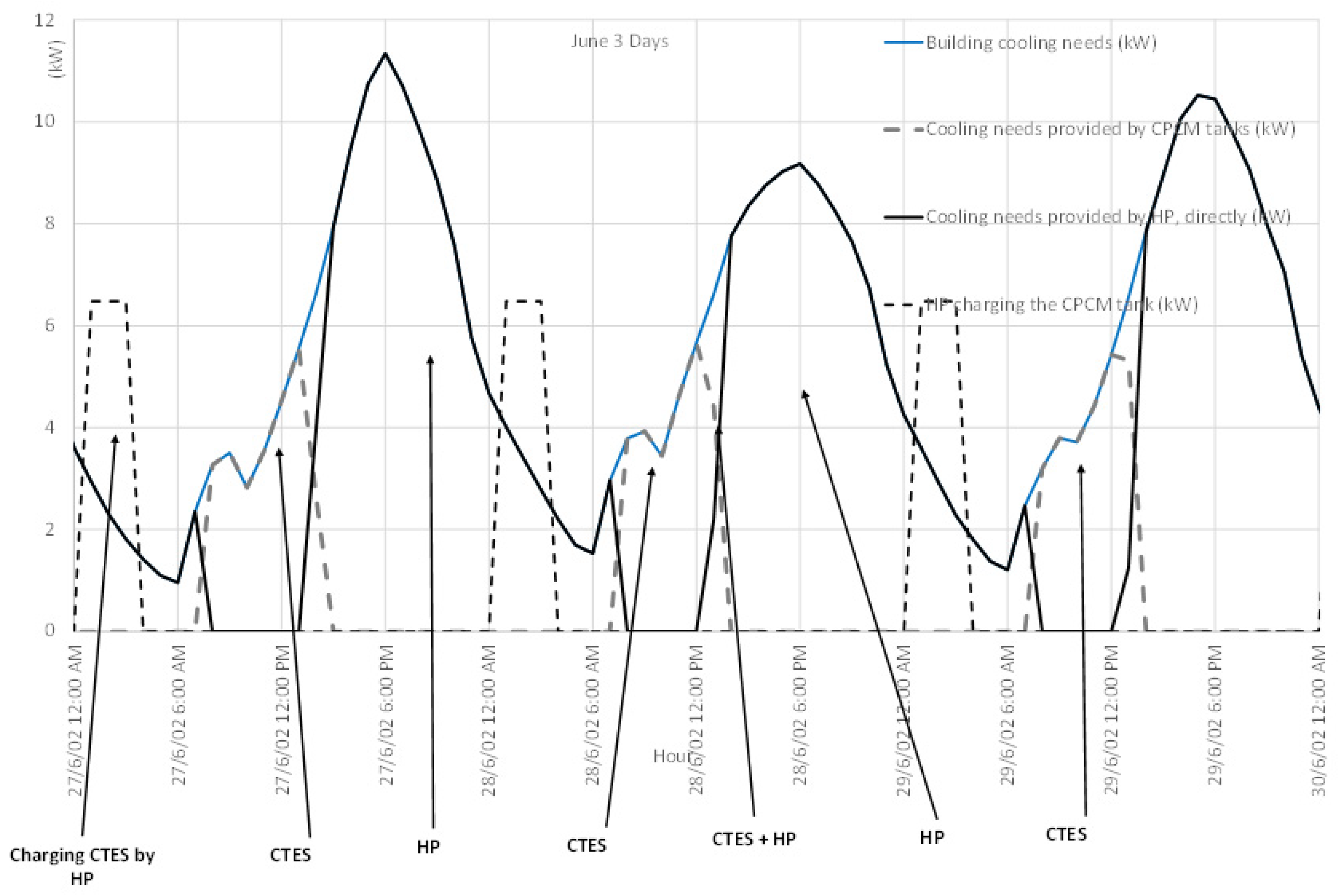
4. Performance Evaluation of TESSe2b System
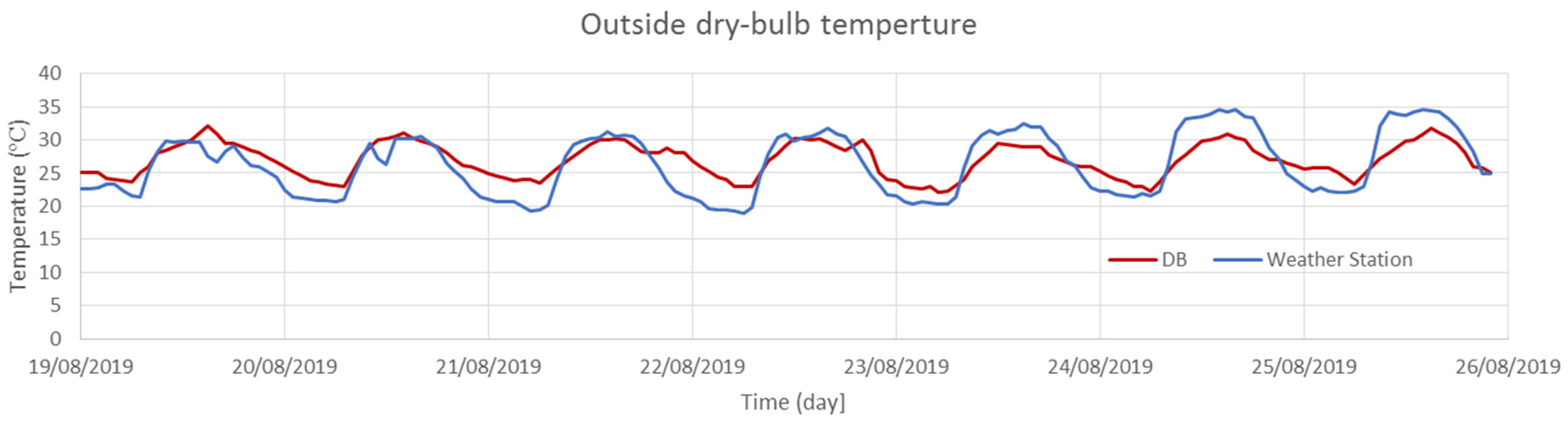
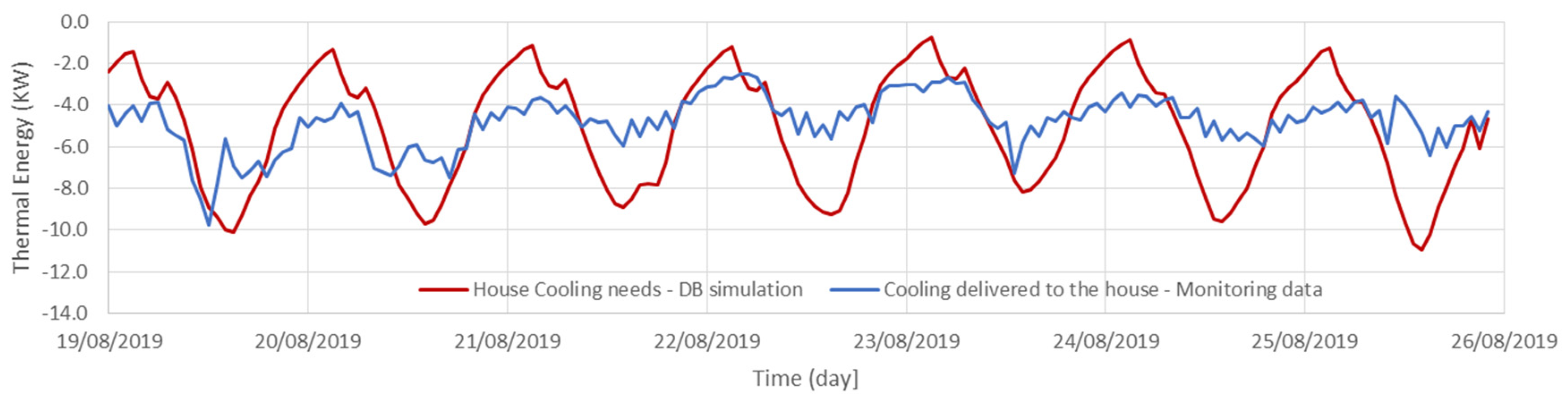
4.1. Methodology

Performance evaluation was attempted in various ways. First, we compared the TESSe2b solution and a conventional heating and cooling residential system that was used in Cyprus, consisting of a boiler and burner using heat oil (heating), split units (cooling) and solar supported by electric heating element DHW. For the TESSe2b energy calculations, the monitoring results during heating and cooling mode were taken into account. The capacity of the conventional system for heating, cooling and DHW as well as the energy consumption were estimated by using all technical characteristics of the building shell, the location of the building (climatic and meteorological data) and the typical use of the dwellings. A conventional system was simulated through Design Builder (DB) in order to provide all appropriate results for the TESSe2b system evaluation.
TESSe2b evaluation was also conducted through different levels of system energy efficiency (symbols CH1, CH2, … refer to circulators, and they are shown in Figure 1) [22]:
  • SPF1: efficiency of the system, including the electricity consumption of the GSHP;
  • SPF2: efficiency of the system, including the electricity consumption of the GSHP and the circulator of the BHEs (circulator CH2);
  • SPF3: efficiency of the system, including the electricity consumption of the GSHP and the circulators CH2, CH1 and CL1;
  • SPF4: efficiency of the system, including the electricity consumption of the GSHP, the circulators CH2, CH1 and CL1 and the fans of the load terminal units of the building.
In order to calculate all energy values, the following assumptions were taken into account: the inlet temperature of the radiators (80 °C), outlet temperature of the boiler 80 °C, volume of the DHW tank (160 L), outlet temperature of the DHW (50 °C) and minimum and maximum temperature of the fresh water (10 °C and 17.5 °C, respectively). In order to calculate the annual energy savings, reduction of the operational cost and simple payback period, the energy heating needs were converted to primary energy according to the relevant factors, as considered in Cyprus and presented here. In parallel, annual CO2 emissions reductions were calculated:
  • Primary energy conversion factor: oil (1.1) and electrical energy (2.9);
  • Emissions TCO2/MWh: oil (0.267) and electrical energy (0.874).
Finally, the TESSe2b system was evaluated through the storage system performance while also considering the required volume to achieve the same results while using water as the storage medium.

4.2. Conventional System and Tesse2b Calculations: Economic Analysis and Discussion

The technical characteristics of the conventional system in Cyprus were the following:
  • Boiler and burner using heat oil of 20 kW for heating;
  • Split units of 15.6 kW for cooling;
  • Solar system of 9.4 m2: 4 collectors for DHW (supported by a heating element).
  • The technical characteristics of the TESSe2b system were the following:
  • GSHP of 26.3 kW for heating and 18.6 kW for cooling;
  • Solar system of 20m2: 10 collectors for heating and DHW;
  • Total of 3 HTES tanks, 3 CTES tanks and 1 DHW-PCM tank.
The equivalent primary energies for the conventional and TESSe2b systems are shown in Table 2 and Table 3.
In order to evaluate the cost effectiveness of the TESSe2b solution, financial calculations were made for the conventional and TESSe2b systems (Table 4) based on the prices in the market of Cyprus. Based on the equivalent primary energy, annual savings were calculated in terms of annual primary energy saving, annual emissions reductions and annual savings from operational and maintenance costs. The cost of a conventional system comprises the cost for an oil boiler and burner (EUR 4000), split units (EUR 10,140) and auxiliary devices (EUR 1450), concluding with a total cost of EUR 15,590. The cost of the TESSe2b system comprises the cost for the heat pump (EUR 26300), solar collectors (EUR 8400), PCM tanks (EUR 4200), control system and auxiliary devices (EUR 2200), with a total cost of (EUR 41100). Finally, the investment criteria for the TESSe2b system for a 25-year period in comparison with the conventional system were the following: a simple payback period (SPBP) of 9.76 years, discounted payback period (DPBP) of 11.26 years (with a discount rate of 2.5%), net present value (NPV) of EUR 25465.41 and internal rate of return (IRR) of 9.51%. It has to be mentioned that both the conventional and TESSe2b systems were newly installed systems.
SPF calculation: Based on the monitoring data for the heating and cooling in the building, the SPFs were calculated as shown in Table 5.
Given the SPF results for the TESSe2b system at the Cyprus demonstration site, we could draw very promising conclusions concerning the TESSe2b system’s performance, especially in cooling mode. First of all, the SPF values were very high during June, July and August, since the TESSe2b system worked very efficiently in cooling mode due to the very high temperatures that dominated in Cyprus. It has to be mentioned that the SPF of the heat pump (SPF1) was 5.77, 5.52 and 5.03 for June, July and August, respectively. Moreover, the results for SPF2, including electricity consumption of the BHEs’ circulator, also showed excellent performance, since there was a slight reduction in relation to SPF1 (i.e., 5.67, 5.44 and 4.96 for June, July and August, respectively). However, a more evident reduction occurred with SPF3 and SPF4 due to the electricity consumption added with the circulators and fans of the entire system. Except for the extraordinary conclusions of the TESSe2b system from June to August, the TESSe2b system’s performance was quite good during April and May, with moderate temperatures during the spring. More specifically, SPF1 was 3.16 and 3.79 in April and May, respectively, which was quite high in such a period where the TESSe2b system was rarely used due to the moderate outside dominant temperatures in Cyprus. Finally, as was already mentioned, there was also a slight reduction in SPF2 and a more significant one in SPF3 and SPF4 that led to satisfying conclusions during the spring anyway.
Storage system performance: In order to evaluate the storage system performance, hourly energy analysis of heating, cooling and DHW production using the operational profiles was performed. The results on an annual basis of the analysis of the PCM tanks for heating and DHW in relation to the solar contribution are presented in Table 6. The results are shown for the building according to the analysis of the TES tanks for heating, cooling and DHW in relation to the solar contribution, and the energy needs shifted from day (higher electricity tariffs) to night (lower electricity tariffs). The results were obtained without influencing the control system and without influencing the PCM in the BHEs, which could contribute to increasing the system’s performance.
In Figure 8, the system’s operation for 3 days in June (cooling mode) is shown. During these 3 days, an important fraction of the cooling needs could be shifted from day (higher electricity tariff) to night (low electricity tariff).
Other important results regarding the performance of the PCM tanks were related to the amount of energy stored and the energy transfer rate (heating or cooling capacity). Table 7 shows the main characteristics of the PCM tanks.
The cooling capacity was higher than the installed capacity of the respective heat pump (18.6 kW), confirming that as long as the PCM tanks had stored energy, they were able to cover all cooling needs even at peak times without any help from the heat pump. The heating capacity was lower than the installed capacity of the respective heat pump (26.3 kW). However, the higher heating capacity installed was only due to the needed cooling capacity, taking into account that in Cyprus, cooling needs are high. The design’s heating capacity was only 17 kW. Even so, the capacity was superior to the tanks. This means that if the tanks were warming up, they may have needed the heat pump support to cover their needs at some peak hours per year.
As the TESSe2b (with TES storage) system was designed and installed in order to maximize the solar fraction due to PCM’s large amount of latent heat in comparison with the energy storage based in sensible heat using water volume storage, it was attempted to evaluate the necessary volume of water that produced the same solar fraction with PCM tanks for heating and DHW using the same area of the solar collectors with energy simulations. It was concluded that the total TES volume required for heating and DHW was 0.64 m3 (in comparison with water energy storage of 6 m3) to achieve the same results. The use of PCM storage required limited space instead of water storage, and this is a very important result.
Furthermore, heating and cooling needs were simulated using Design Builder (DB) software. All the characteristics of the building’s thermal envelope were used. The weather data used were based on the Paphos climate file in the Design Builder database. In order to validate the weather data, they were compared with those obtained by the weather station installed on the demo site. Good agreement was found between the two datasets for an entire year. A week with identical weather data between the Design Builder database and the weather station data was chosen during the cooling season. The week analyzed was the week from 19 to 26 August. Figure 9 shows sufficient agreement between the simulation results and demo site monitoring. The slight variations in the monitoring data had to do with the dead band set for temperature control, while the influence of the thermal inertia of the water within the distribution system was taken into account. As the simulation adequately represented the actual functioning of the building, realistic conclusions can be drawn regarding the performance of the conventional system and the TESSe2b system.
Figure 10 represents the evolution of the calculated building cooling needs and the energy delivered to the building by the TESSe2b system to satisfy the space’s cooling needs.
The energy delivered by the TESSe2b system to the building that week to meet its cooling needs was 806.7 kWh, while the value predicted by the simulations was 846.7 kWh, showing a relative difference of 5.1%, which is considered acceptable.
In Figure 11, the solar radiation calculated by the software and measured by the weather station is shown. Paphos is on the coast, and the demo site, despite being located near Paphos, was a little further inland, which yielded a slightly higher daily thermal amplitude. However, it was considered that the agreement between the weather data was adequate for the analysis performed.
Figure 12 and Figure 13 present the DHW TES tank performance based on the monitoring data recorded on 24 August 2019. During the cooling season, the solar collectors only provided thermal energy to the DHW TES tank. The level of charge of the DHW TES tank depended on the balance between the solar energy available and the rate of DHW consumption. The results presented are representative of most of the cooling season days, indicating that the DHW TES tank was almost fully charged continually, and the total mass of the PCM was fully melted (Figure 12).
The discharge of the thermal energy to the DHW is presented in Figure 13. The process was characterized by a large heat transfer rate that decreased as the process progressed. The initial high value of the heating rate was due to the high temperature inside the DHW TES tank.

5. Conclusions

In this work, performance evaluation results for the TESSe2b system when it was applied in a residential building in a Mediterranean climate were presented and discussed. The typical conclusions are as follows:
The TESSe2b storage system resulted in occupying several times less space than a similar system with water as a storage medium instead of PCM. Furthermore, with a calculated payback time of about 9.8 years, and taking into account the significant cost reduction during a commercialization phase, the TESSe2b solution became financially attractive.
The system had an equivalent primary energy for heating, cooling and DHW equal to 8397.7 kWh. For comparison, the same value for a conventional system was calculated to be 43,335.0 kWh. For the summer months, the GSHP had an SPF1 ranging from 5.77 in June to 5.03 in August. The addition of the electrical consumption of the boreholes (SPF2) reduced the factor slightly (from 5.67 to 4.96). Including all devices, the factor (SPF4) reduced to 3.80–3.64.
According to the data collected during the operation of the system, the solar contribution for heating and DHW yielded a solar fraction of 42.3%. The significance of the energy storage was highlighted by the 44.8% shift in the heating needs from day to night and by the 30.3% shift in the cooling needs. Shifting the cooling needs to low electricity tariff hours was a beneficial aspect of the system. Moreover, the average heat transfer rate resulted in being as high as 13.5 kW for heating and 31.5 kW for cooling. The DHW that the system could deliver was between 40 and 50 °C. Considering the stored energy, 21.9 kWh were measured in the space heating tanks, while 14.5 kWh in the cooling tanks and 6.2 kWh in the DHW tank were found.
Regarding the software predictions, the default outside temperature data of the software were in good agreement with those provided by the weather station installed in the building. The cooling thermal power delivered to the building had less fluctuations and with a higher frequency than those predicted by the software. However, the real total energy delivered and the computed value had only a 5.1% difference. Furthermore, the solar irradiation calculated by the software and that measured by the weather station were in perfect agreement almost every day. Finally, for a hot summer day when the solar collectors provided energy only to the DHW tank, the temperature measured inside the tank showed that the PCM managed to fully melt in the day, and thus the DHW tank was fully charged. During discharging, high rates of heat transfer were measured (above 60 kW), and thus the fast heating of the main water during its passing through the DHW tank was guaranteed.
The PCMs were selected after experimental evaluation among different options and resulted in a full phase change for each operation (i.e., cooling, heating and DHW). A future challenge is to improve or select PCMs that will store more energy at the same size of the tank.
The main shortcoming of the method used has to do with the difficulty of evaluating the individual performance of each component of the system and its contribution to the performance of the system as a whole. It should be noted that the energy performance of the TES tanks was properly optimized and evaluated, but this article did not aim to present this specific work.
The main advantage of the method is that it allows for evaluating the performance of the system as a whole and the importance of using TES solutions to increase energy efficiency and increase the share of RES for heating, cooling and DHW for residential buildings compared with traditional systems.

Author Contributions

Conceptualization, L.C., M.G.V., C.K. and C.S.; methodology, L.C., M.G.V., C.K., C.S. and M.K.K.; software, C.S. and A.R.; validation, all; formal analysis, M.K.K., J.K., Z.C., G.D., A.R. and A.B.; investigation, M.K.K., J.K., G.D., A.R. and A.B.; writing—original draft preparation, G.D. and M.K.K.; writing—review and editing, M.K.K., G.D., J.K., A.B. and J.C.; supervision, L.C. and M.G.V.; project administration, L.C.; funding acquisition, M.G.V. and L.C. All authors have read and agreed to the published version of the manuscript.

Funding

The TESSe2b project has received funding from the European Union’s Horizon 2020 Research and Innovation Programme under grant agreement number 680555. This article reflects only the authors’ views, and the Commission is not responsible for any use that may be made of the information it contains.

Institutional Review Board Statement

Not applicable.

Informed Consent Statement

Not applicable.

Data Availability Statement

Not applicable.

Conflicts of Interest

The authors declare no conflict of interest.

References

  1. International Renewable Energy Agency. Innovation Outlook—Thermal Energy Storage; International Renewable Energy Agency: Abu Dhabi, United Arab Emirates, 2020. [Google Scholar]
  2. Douvi, E.; Pagkalos, C.; Dogkas, G.; Koukou, M.K.; Stathopoulos, V.N.; Caouris, Y.; Vrachopoulos, M.G. Phase Change Materials in solar Domestic Hot Water Systems: A Review. Int. J. Thermofluids 2021, 10, 100075. [Google Scholar] [CrossRef]
  3. Delgado, M.; Lazaro, A.; Mazo, J.; Zalba, B. Review on Phase Change Material Emulsions and Microencapsulated Phase Change Material Slurries: Materials, Heat Trnasfer Studies and Applications. Renew. Sustain. Energy Rev. 2012, 16, 253–273. [Google Scholar] [CrossRef]
  4. European Association for Storage of Energy and European Energy Research Alliance. Joint EASE/EERA Recommendations for a European Energy Storage Technology Development Roadmap towards 2030; Martens, D., Ed.; EASE/EERA: Brussels, Belgium, 2013. [Google Scholar]
  5. Pandey, A.; Hossain, M.; Tyagi, V.; Abd Rahim, N.; Selvaraj, J.; Sari, A. Novel Approaches and Recent Developments on Potential Applications Phase Change Materials in Solar Energy. Renew. Sustain. Energy Rev. 2018, 82, 281–323. [Google Scholar] [CrossRef]
  6. Faraj, K.; Khaled, M.; Faraj, J.; Hackem, F.; Castelain, C. A Review on Phase Change Materials for Thermal Energy Storage in Buildings: Heating and Hybrid Applications. J. Energy Storage 2020, 1, 101913. [Google Scholar] [CrossRef]
  7. Mehling, H.; Cabeza, L. Heat and Cold Storage with PCM; Springer: New York, NY, USA, 2008. [Google Scholar]
  8. Agyenim, F.; Hewitt, N.; Eames, P.; Smyth, M. A Review of Materials, Heat Transfer and Phase Change Problem Formulation for Latent Heat Thermal Energy Storage Systems (LHTESS). Renew. Sustain. Energy Rev. 2010, 14, 615–628. [Google Scholar] [CrossRef]
  9. Aljabr, A.; Chiasson, A.; Alhajjaji, A. Numerical Modeling of the Effects of Micro-Encapsulated Phase Change Materials Intermixed with Grout in Vertical Borehole Heat Exchanger. Geothermics 2021, 96, 102197. [Google Scholar] [CrossRef]
  10. Yang, W.; Xu, R.; Yang, B.; Yang, J. Experimental and Numerical Investigations on the Thermal Performance of a Borehole Ground Heat Exchanger with PCM Backfill. Energy 2019, 174, 216–235. [Google Scholar] [CrossRef]
  11. Kocak, B.; Fernadez, A.; Paksoy, H. Review on Sensible Thermal Energy Storage for Industrial Solar Applications and Sustainability Aspects. Solar Energy 2020, 209, 135–169. [Google Scholar] [CrossRef]
  12. TESSe2b—The Smart Energy Storage. Available online: http://www.tesse2b.eu/ (accessed on 5 November 2021).
  13. Dogkas, G.; Konstantaras, J.; Koukou, M.K.; Vrachopoulos, M.G.; Pagkalos, C.; Stathopoulos, V.N.; Pandis, P.K.; Lymperis, K.; Coelho, L.; Rebola, A. Development and Experimental Testing of a Compact Thermal Energy Storage Tank using Paraffin Targeting Domestic Hot Water Production Needs. Therm. Sci. Eng. Prog. 2020, 19, 100573. [Google Scholar] [CrossRef]
  14. Dogkas, G.; Koukou, M.K.; Konstantaras, J.; Pagkalos, C.; Lymperis, K.; Stathopoulos, V.; Coelho, L.; Rebola, A.; Vrachopoulos, M.G. Investigating the Performance of a Thermal Energy Storage Unit with Paraffin as Phase Change Material, Targeting Building’s Cooling Needs: An Experimental Approach. Int. J. Thermofluids 2020, 3–4, 100027. [Google Scholar] [CrossRef]
  15. Koukou, M.K.; Dogkas, G.; Vrachopoulos, M.G.; Konstantaras, J.; Pagkalos, C.; Stathopoulos, V.N.; Pandis, P.K.; Lymperis, K.; Coelho, L.; Rebola, A. Experimental Assessment of a Full-Scale Prototype Thermal Energy Storage Tank Using Paraffin for Space Heating Application. Int. J. Thermofluids 2020, 1–2, 100003. [Google Scholar] [CrossRef]
  16. CORESA Savings. Deliverable 7.2-Performance Evaluation Report and Economic Feasibility Study of TESSE2B Solution Small Scale Validation in Cyprus. Center Renew. Energy Sources Sav. 2019, 1, 1–35. [Google Scholar]
  17. Coelho, L.; Rebola, A.; Passaro, J.; Koukou, M.K.; Vrachopoulos, M.G.; Karytsas, K.; Benou, A.; Goldbrunner, J.; Gaich, H.; Evangelakis, G.; et al. Thermal Energy Storage an Overview of one Advanced System Based on the European TESSE2B Project. In Proceedings of the EinB2019—8th International Conference “Energy in Buildings 2019”, Athens, Greece, 28 September 2019. [Google Scholar]
  18. Pagkalos, C.; Koukou, M.K.; Vrachopoulos, M.G.; Konstantaras, J.; Dogkas, G.; Stylianou, S.; Stathopoulos, V.; Lymperis, K. Design of Thermoplastic Tanks for Thermal Energy Storage Applications Using Finite Element Analysis. In Proceedings of the EinB2019-8th International Conference “Energy in Buildings 2019”, Athens, Greece, 28 September 2019. [Google Scholar]
  19. Chalkia, V.; Tachos, N.; Pandis, P.K.; Giannakas, A.; Koukou, M.K.; Vrachopoulos, M.G.; Coelho, L.; Ladavos, A.; Stathopoulos, V.N. Influence of Organic Phase Change Materials on the Physical and Mechanical Properties of HDPE and PP Polymers. RSC Adv. 2018, 48, 27438–27447. [Google Scholar] [CrossRef] [Green Version]
  20. Cyprus Department of Meteorology, Seasonal Forecasts for South East Europe. Available online: http://www.moa.gov.cy/moa/dm/dm.nsf/seecof_en/seecof_en?OpenDocument (accessed on 1 December 2021).
  21. DesignBuilder Software Ltd. DesignBuilder Help v7.0. Available online: https://designbuilder.co.uk/helpv7.0/ (accessed on 23 September 2021).
  22. European Union. Commision Decision of 1 March 2013 Establishing the Guidelines for Member States on Calculating Renewable Energy from Heat Pumps from Different Heat Pump Technologies Pursuant to Article 5 of Directive 2009/28/EC of the European Parliament and the Council. Off. J. Eur. Union 2013, 1, 27–35. [Google Scholar]
Figure 1. TESSe2b hydraulic scheme for a building in Cyprus [16]. MTV = manual triode valve; DTV = digital two-way valve; C = circulation pump; DV = digital triode valve; AV = analog triode valve; TV = thermostatic valve; EWH = electric water heater; T = temperature sensor; F = flow meter; J = electricity meter.
Energies 15 01008 g001
Figure 2. TES tanks (HTES, CTESs or DHW).
Energies 15 01008 g002
Figure 3. External view of the building—East. (A) = actual building, (B) = geometric model.
Energies 15 01008 g003
Figure 4. Solar collectors on the roof.
Energies 15 01008 g004
Figure 5. BHE locations.
Energies 15 01008 g005
Figure 6. Overview of TESSe2b control and monitoring system implementation.
Energies 15 01008 g006
Figure 7. View of the engine room.
Energies 15 01008 g007
Figure 8. Indicative system operation for three days in June (cooling mode).
Energies 15 01008 g008
Figure 9. Dry bulb Temperature recorded by the weather station and from the DB climate data file for the Cyprus simulations.
Energies 15 01008 g009
Figure 10. Cooling delivered to the house by the TESSe2b system and cooling needs obtained by the DB simulations.
Energies 15 01008 g010
Figure 11. Solar radiation intensity on a horizontal surface recorded by the weather station and from the DB climate data file for the Cyprus simulations.
Energies 15 01008 g011
Figure 12. DHW TES tank temperature on 24 of August 2019.
Energies 15 01008 g012
Figure 13. Heat transfer rate from the DHW TES tank to the DHW delivered to the house on 24 of August 2019.
Energies 15 01008 g013
Table 1. Estimated capacities and energy needs.
ModeCapacity
(kW)
Capacity per Area
(W/m2)
Annual Needs
(kWh)
Annual Needs per Area
(kW/m2)
Heating17.076.91521168.8
Cooling18.684.21481367.0
Table 2. Equivalent primary energy for the conventional system.
Equivalent Primary Energy—Conventional System
Oil consumption for space heating (kWh)18,809.0
Equivalent primary energy for space heating (kWh)20,689.9
DHW electricity consumption (kWhe)204.2
Equivalent primary energy for DHW (kWh)592.3
Electricity consumption for cooling (kWhe)7060.4
Equivalent primary energy for Cooling (kWh)22,052.8
Total equivalent primary energy (kWh)43,335.0
Table 3. Equivalent primary energy for the TESSe2b system.
Equivalent Primary Energy—TESSe2b System
Electricity consumption for heating/cooling/DHW (kWh)2895.8
Equivalent primary energy for heating/cooling/DHW8397.7
Table 4. Annual savings.
Annual Savings
Annual primary energy saving (kWh)34,937.2
Annual primary energy saving (%)80.6
Annual emissions reduction (TCO2)11.8
Maintenance cost of TESSe2b (€)160.0
Annual operational & maintenance cost of TESSe2b (€)623.3
Maintenance cost of Conventional System (€)220.0
Annual operational & maintenance cost of Conventional System (€)3237.1
Annual savings from operational & maintenance cost (€)2613.7
Annual savings from operational & maintenance cost (%)81.7
Table 5. Seasonal Performance Factors for the year 2019.
SPF1SPF2SPF3SPF4
April3.163.142.712.66
May3.793.772.842.82
June5.775.674.293.80
July5.525.444.443.79
August5.034.964.173.64
Table 6. Solar contribution and energy needs shifted from day to night.
Solar CollectorsSolar Fraction HeatingSolar Fraction Heating + DHWHeating Needs Shifted Day to Night (Total Solar)Cooling Needs Shifted Day to Night
1030.5%42.3%44.8%30.3%
Table 7. Energy stored and energy transfer rate of TES tanks.
VariableValue
Number of HTES tanks3
Total energy stored (heating) (kWh)21.9
Average TES capacity (heating) (kW)13.5
Number of CTES tanks3
Total energy stored (cooling) (kWh)14.5
Average TES capacity (cooling) (kW)31.5
Number of DHW_PCM tanks1
Total energy stored (DHW) (kWh)6.2
Supply water temperature (°C)40–50
Publisher’s Note: MDPI stays neutral with regard to jurisdictional claims in published maps and institutional affiliations.

