Article

Relay Protection Setting Calculation System for Nuclear Power Plant Based on B/S Architecture and Cloud Computing

1
School of Information and Electric Engineering, Shandong JiaoTong University, Jinan 250357, China
2
State Grid Liaoning Electric Power Co., Ltd., Shenyang 110004, China
3
Shan Dong Cheersun Intelligent Technology Co., Ltd., Jinan 250101, China
4
State Key Lab of Control and Simulation of Power Systems and Generation Equipment, Department of Electrical Engineering Tsinghua University, Haidian District, Beijing 100084, China
*
Author to whom correspondence should be addressed.
Energies 2022, 15(24), 9648; https://doi.org/10.3390/en15249648
Submission received: 30 November 2022 / Revised: 14 December 2022 / Accepted: 15 December 2022 / Published: 19 December 2022
(This article belongs to the Topic Power System Protection)

Abstract

:
Nuclear power plants have a complex structure and changeable operation mode, which induces low setting calculation efficiency. After analyzing the technology, architecture, and functional logic of a variety of relay protection setting calculation systems and combining the characteristics of the setting calculation of nuclear power plants, the relay protection setting calculation system in nuclear power plants based on B/S architecture and cloud computing is studied in this paper. The system adopts three-tier B/S architecture, applies two key technologies, the cloud computing task distribution synchronization mechanism and the cloud component automatic assembly mechanism, and introduces a particle swarm optimization algorithm to provide technical support for nuclear power plant setting calculation; the running example of the nuclear power plant system fully proves the efficiency and reliability of the relay protection setting calculation system of the nuclear power plant, which has high practical value.

1. Introduction

As a clean energy source, nuclear energy has more stable advantages than wind power, photovoltaic power, and hydropower. In China, nuclear power has been gradually expanded, new generator sets have been put into operation, and the scale of nuclear power plants has continued to grow [1,2,3]. There are many types of reactors currently in operation and under construction (M310, VVER, AP1000, CANDU, HRP, HTGR, etc.), and therefore, it is extremely important to ensure the safety of nuclear power plants [4].
The safety of nuclear power plants depends on the safety and reliability of the power supply system in the plant. There are many types of equipment in nuclear power plants, and there are many protection principles for each piece of equipment, such as main transformers, generators, excitation transformers, and high-auxiliary transformers, and there are about 40 kinds of protection for a generator and transformer system [5]. Considering the large number of equipment components in each generator of the nuclear power plant, the extremely complex topology structure, the changeable operation mode of nuclear power, the complex coupling characteristics of various electrical and non-electrical quantities, etc., the protection setting calculation of such various principles will produce huge calculation cases and topology search paths, and the difficulty of setting management has increased sharply. Traditional fault analysis and relay protection setting technologies are facing huge challenges [6,7].
The traditional power grid equipment relay protection setting calculation system is based on C/S architecture (client/server architecture); under this architecture, the setting calculation process is completed on the client, and the calculation occupies a lot of computer resources [8]. When this type of architecture is applied to the nuclear power plant relay protection setting calculation system, the user’s computer will run slowly due to insufficient resources, making it difficult to complete the nuclear power plant setting calculation work with a large number of calculation nodes, even affecting the operation of other work systems. At the same time, the upgrade and maintenance of the system also need to be operated computer-by-computer, which affects the data security and normal production of the nuclear power plant [9,10]. There is no vertical comparison means for the generators of the same model, and there also is no horizontal comparison means for generators with the same capacity in different nuclear power plants, which is not conducive to the verification of the accuracy of the relay settings [11]. Therefore, nuclear power plants have put forward higher requirements for calculation efficiency improvement and advanced application development of the relay protection setting calculation system [12,13,14,15].
According to the above issues, some schemes have been proposed in other studies. An integrated system of relay protection setting calculation and setting management based on C/S and B/S (browser/server architecture) hybrid network architecture has been designed; which is divided into a C/S-based setting calculation subsystem and a B/S-based setting management subsystem. Compared with the traditional C/S architecture setting calculation system, the network transmission control of the setting sheet and search and printing functions of setting were completed, which makes the setting management more normalized, institutionalized, and standardized. However, because the B/S architecture is only applied in the setting management in this method, the setting calculation subsystem that needs to perform a large amount of calculation has not yet broken away from the technical limitations of the C/S architecture, and the improvement of the setting calculation efficiency is limited [16]. A relay protection setting calculation system using a three-tier C/S structure system was proposed; the three-tier structure separates user interface and business logic, which simplifies client software, as the client completes Interface Program Logic, the application server completes operation processing logic, and the database server completes data access logic; the three-tier architecture can reduce network data communication and ease calculation pressure on clients. However, since this method can only be used for relay protection setting calculation with a single server, which limits the upper limit of calculation speed, at the same time, the client program needs to be replaced when the C/S architecture system is upgraded, which makes it difficult to meet the requirements of setting calculation for nuclear power plants [17,18].
The following issues need to be studied in research on the relay protection setting calculation system of nuclear power plants:
1. What type of system architecture is most suitable for the relay protection setting calculation of nuclear power plants?
2. How can the relay protection setting calculation efficiency of nuclear power plants be comprehensively improved?
To solve the above problems, the framework and structure of the relay protection setting calculation system for nuclear power plants are studied in Chapter 2 of this paper, and the key technologies of cloud computing are studied in Chapter 3.

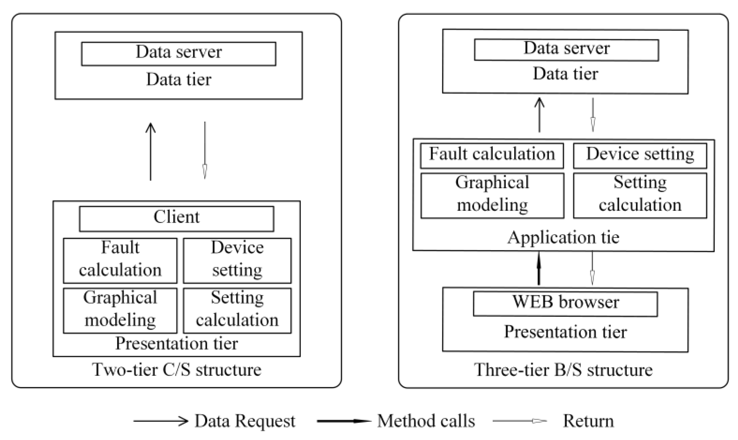
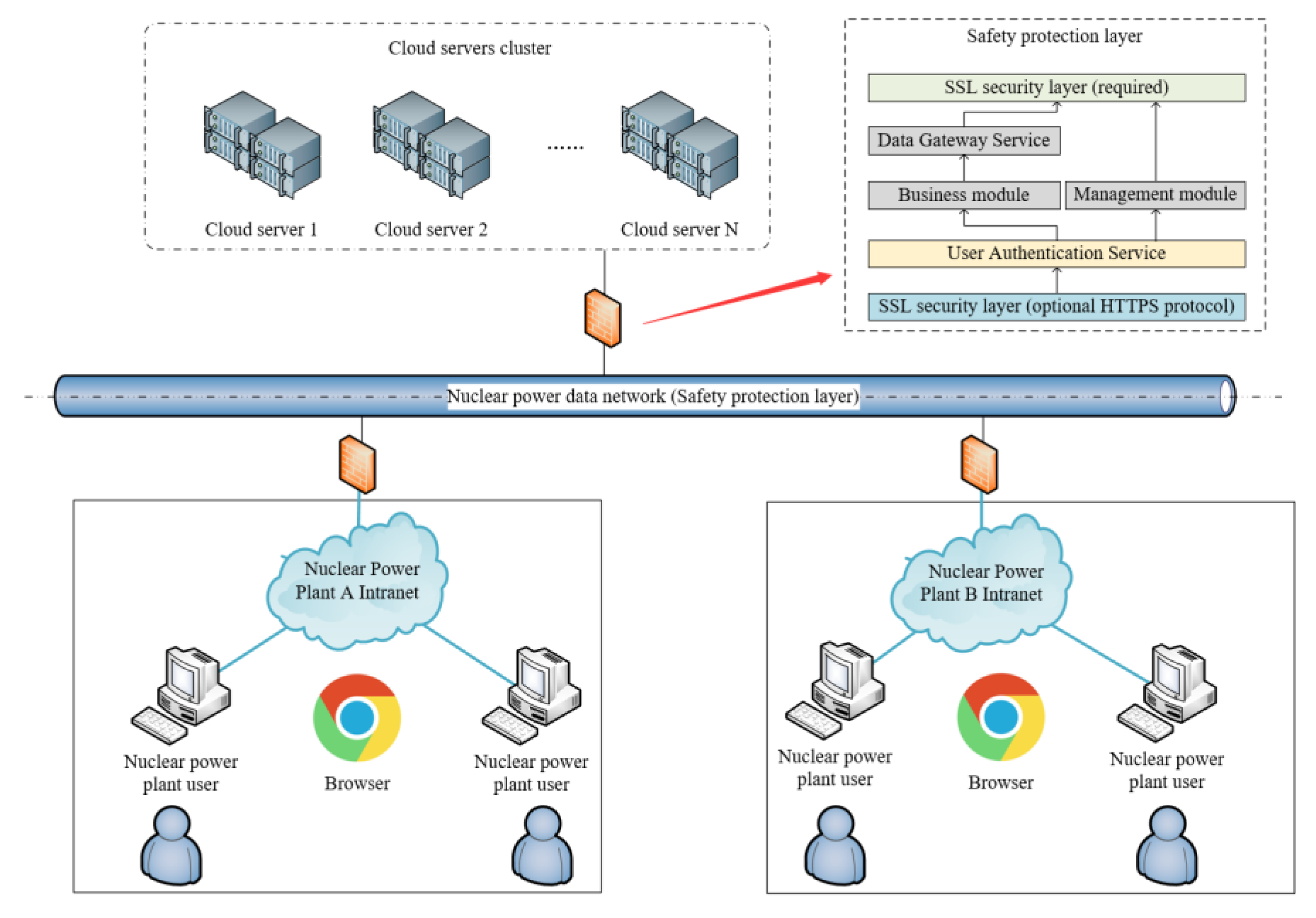
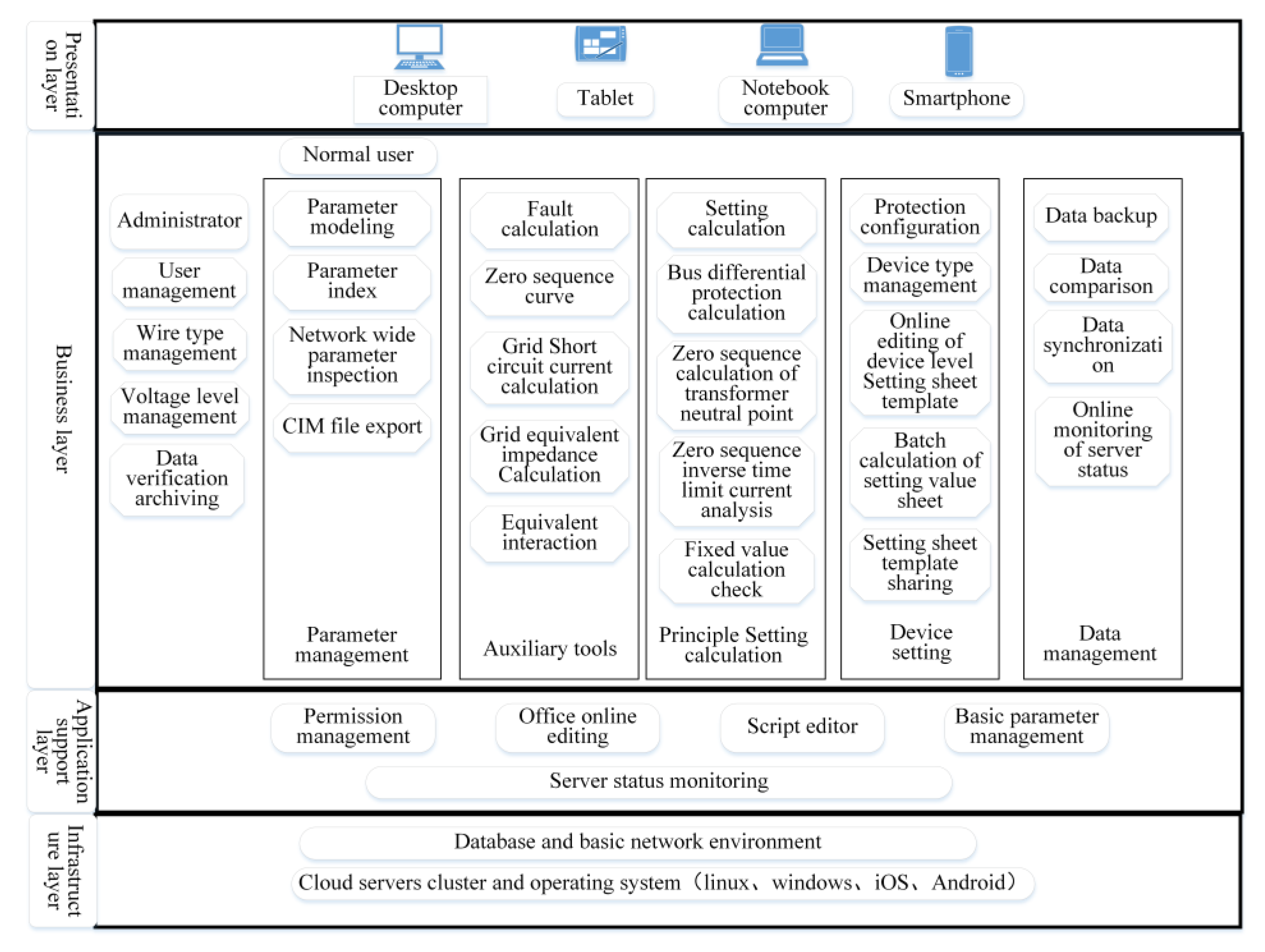
2. Architecture and Ideas

Nowadays, more and more nuclear generator units are being put into operation, and the task of setting calculation is getting heavier. In the traditional two-tier C/S architecture, a client program usually corresponds to a fixed server program, or a configuration file is used to specify the servers to be communicated with, and it is difficult to achieve automatic expansion, adaptation, and cloud computing scenarios. Nuclear power plants have high demands for the data sharing and operational convenience of relay protection setting calculation, and it is urgently required to introduce cloud computing technology into the setting calculation system.
In the traditional two-tier architecture, it is difficult to separate the interface, business logic, and data access from each other, especially in many business logics, because there is no clear design boundary, and direct database access often occurs in the interface layer or in the response code of the calling interface, which makes the design architecture of the system simple, but the logical coupling expands rapidly with the growth of the system function and scale. As the system life cycle evolves, the degree of coupling can easily rise from the initial message coupling and control coupling to the public coupling, or even to the most serious content coupling, making the later maintenance and expansion difficult or even out of control. The three-tier B/S architecture defines the functional boundary between the business logic and the data access layer, adds a layer of communication points in the process of business calls, and requires more constraints at the design and implementation levels, which also reduces the complexity of sub-modules and the coupling degree of the Inter module. The interaction between modules, the integration of business logic processing modules, the independence of the data access layer, and the decoupling between interface and business logic reflect the complexity of the system, the independence of the data access layer, and the decoupling between the interface and business logic. Although there is a lot of work in the design phase, when the architecture model and data model are determined, it is only necessary to observe the design specifications of the three-tier architecture style in the implementation process; for example, message middleware technology is introduced to handle the interaction between distributed business logic layers, http call request interceptors are added to securely verify all interface calls, and the independence and portability of the DAL layer are ensured by introducing Mybatis database middleware. The comparison between the two architectures is shown in Figure 1.
Compared with the two-tier B/S structure, the three-tier B/S architecture is designed as follows:
The first tier is the presentation tier, which mainly completes the interaction between the user and the application program, drawing the primary electric wiring of the substation, inputting the parameters of the generator transformer unit, or displaying the fault calculation results [19,20].
The second tier is the application tier, which processes the information collected from the presentation tier according to the business logic (such as equivalent circuit model, fault calculation, and setting logic). It is the core of the application program, also called the logic tier or the intermediate tier (BLL).
The third tier is the data tier, which is used to store and manage equipment parameters, equivalent models, protection information (CT/PT transformation ratio, maximum load current, protection settings, equipment types), etc. of nuclear power plants; it is sometimes called the database tier, data access tier (DAL), or back-end [21,22].
The three-tier architecture introduces the concepts of BLL and DAL on the basis of the two-tier architecture. When the front-end interface calls the back end, a series of data business logic processing such as permission verification, security verification, calculation, and data organization using business rules must be carried out first through the business logic layer. The business logic layer, as the bridge between the front-end interface and the data access layer, does not directly operate the database, and the specific details of the front-end message call are shielded for the data access layer. By using the three-tier B/S architecture, cloud computing technology can be introduced into the setting calculation system, and huge setting calculation cases can be distributed to different servers for parallel calculation, making full use of the calculation resources of multiple servers, and greatly improving the calculation speed.
The relay protection setting calculation system of a nuclear power plant based on B/S architecture and cloud computing shown is Figure 2 adopts the scheme of centralized deployment, in which the cloud server cluster is connected to the internal private network of the nuclear power plant through the data network of the Nuclear Power Group, and the client systems of nuclear power plants share the setting calculation cloud server. The setting calculation engineers access the setting calculation system through the browser to perform the setting calculation of the responsible generators separately; at the same time, the usage of this architecture can provide a framework basis for cloud computing services for the setting calculation system, where the system automatically calls the cloud server cluster resources for calculation and returns the calculation results, which ensures the calculation efficiency and transmission efficiency of the setting calculation.
According to reference [23], nuclear power plants have high safety protection standards for computer systems, so relevant safety protection strategies have been adopted in the system architecture design. The server of the relay protection setting calculation system of nuclear power plants has a more rigorous defense system when facing a large number of unknown users, SSL security protocol is used for all database connections, all user operations need to be verified by the user authentication service, operation logs are recorded, private data between users are isolated from each other, and read-only data permission configuration is supported. The server configuration supports HTTPS secure communication, and all browser–server interaction content will be encrypted for transmission [23].

3. Cloud Computing Key Technologies

To improve the calculation efficiency and ensure the full utilization of all server resources, the relay protection setting calculation system of nuclear power plants based on B/S architecture and cloud computing adopts the task distribution synchronization mechanism of cloud computing; at the same time, to meet the multiple requirements of nuclear power plant setting calculation applications, the automatic assembly mechanism of cloud components is adopted.

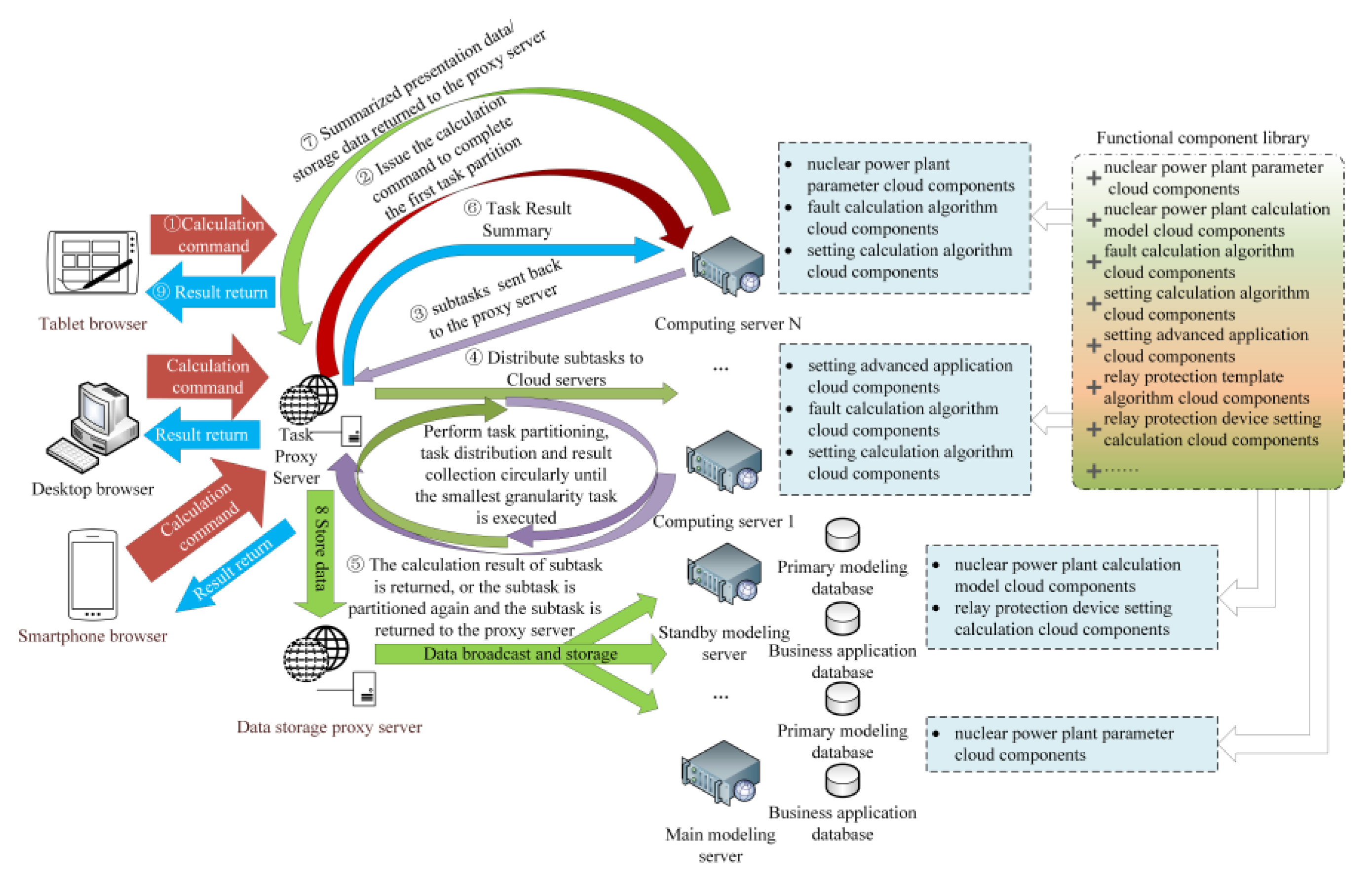
3.1. Cloud Computing Task Distribution Synchronization Mechanism

In order to use cloud computing in setting calculation, the key is how to design the partitioning and cooperating setting mechanism in the setting process, which can maximize the calculation efficiency and ensure the accuracy of the results of the calculation tasks summarized by each server. The cloud setting calculation task partitioning synchronization process is shown in the Figure 3.
In the process of setting calculation, the data preprocessing of the nuclear power plant is started first, the basic data such as the topology and equipment parameters of the nuclear power plant are converted into calculation model data, and the data are distributed from the database server to each application computing cloud server through the data storage proxy server by the broadcast mechanism, which ensures that the data of each application server is consistent and loaded into server memory during cloud computing and that the physical separation of the application server and the database server does not affect the computing performance. Data consistency can be achieved through data distribution. Because of the physical separation of the two servers, the number of application servers can be increased without limitation to improve computing performance.
When a calculation task is determined, the client automatically sends a calculation request to the load balancer, and the task proxy server of the load balancer automatically sends the entire calculation project as a primary task to the master server in the back-end framework for processing.
The primary server performs task analysis to determine whether the primary task needs to be partitioned. If the calculation amount is smaller, the cloud components in the primary server are directly called to process the calculation and return the results. If the calculation amount is larger, and large-scale data or multiple coordination rules need to be calculated, the master server will partition the main task into multiple subtasks layer by layer according to the protection observation points, coordination rules, analysis formula, and calculation cases, and with the cooperation of the task proxy server and all online cloud servers, the subtasks are partitioned to the minimum granularity that cannot be further partitioned, which is a single calculation task, and then each cloud server calls the fault calculation cloud component for parallel computing; when the minimum granularity subtask calculation is completed, the system will perform calculation results receipt operations in the order of cloud servers—task proxy server—master server. The master server summarizes the calculation results of all subtasks and submits them to the task proxy server. The final summary results are forwarded to the data storage proxy server, and then the data storage proxy server broadcasts the results to all online cloud servers for cloud storage; at the same time, the task proxy server returns the summary results to the client browser, and the cloud computing process ends [24,25,26,27,28].
With the application of cloud computing, setting calculation speed will be further improved; the larger the calculation data scale is, and the more complex the calculation method is, the more obvious the advantage is.

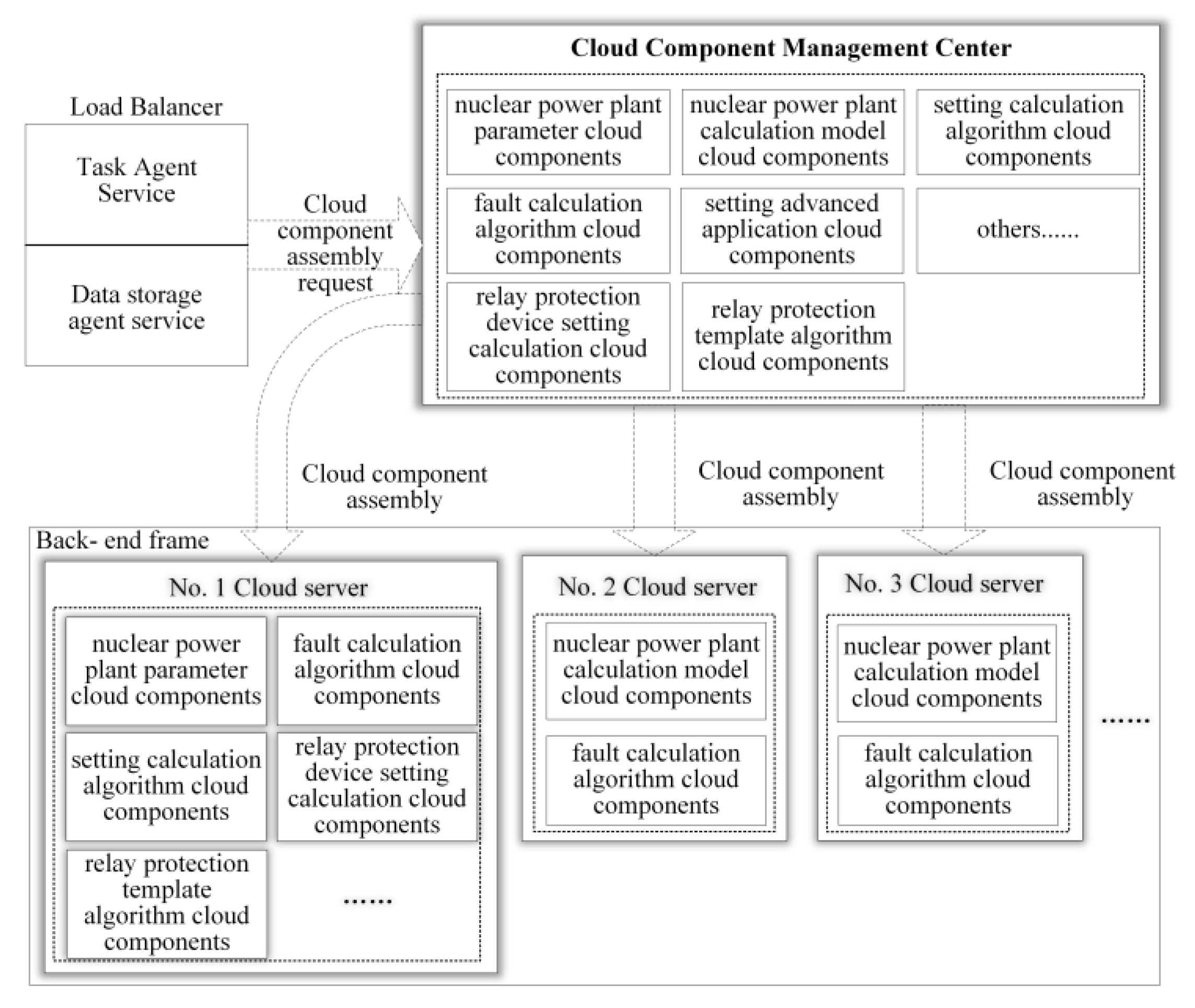
3.2. Automatic Assembly Mechanism of Cloud Components

With the development of nuclear power, more and more functions need to be developed for setting calculation systems, and the functional differences brought by custom development become more and more complex. To solve this problem, the original method is that the system back-end, like the front-end, separates the business and layers the code through a modular structure, but a large number of code layers will make the system structure too deep, redundant, and complex, reduce maintainability, and affect the efficiency of the system. To implement free assembly software development through component technology, an assemblable cloud component model is designed. Cooperating with cloud components to achieve the function of setting calculation applications, cloud components are the smallest functional unit and service deployment unit of application services [29,30,31].
The cloud relay setting calculation system for nuclear power plants adopts a framework of cloud componentized back-end cloud components, which is composed of the client, cloud component management center, load balancer, and back-end framework. The cloud component management center, load balancer, and back-end framework can be deployed separately to different cloud servers. The load balancer includes task agent services and data storage agent services based on the AMQP protocol. The back-end framework involves multiple cloud servers. The load balancer dynamically configures cloud component work according to the load status and performance of the cloud servers and sends cloud component assembly requests to the cloud component management center according to configuration information or operation instructions. The cloud component management center dynamically sends jar packages, scripts, etc. to the cloud servers according to the request to complete the cloud component assembly.
The back-end cloud component covers the complete relay protection setting calculation function. The setting calculation services are classified into single functions which are developed by the cloud componentized method and stored in the cloud component management center in the form of software packages. Through reference, the cloud components are embedded into the native system with zero invasion and low coupling, and different individual cloud servers can be customized according to user requirements or server performance so that there are both dedicated servers to maintain special data and cloud servers to provide computing support, which improves work efficiency.
Figure 4 shows the logical process of assembling a cloud server cluster. During system deployment, the cloud component management center and load balancer are first installed and configured to two servers, and then the main server of the back-end framework is installed to cloud server 1. The nuclear power plant parameter cloud components, nuclear power plant calculation model cloud components, fault calculation algorithm cloud components, setting calculation algorithm cloud components, setting advanced application cloud components, relay protection template algorithm cloud components, and relay protection device setting calculation cloud components are assembled to the No. 1 server through the instruction, so the system has the functions of maintaining the parameters of nuclear power units, calculating user-defined fault calculation cases, setting coordination calculation, and device setting calculation.

3.3. Operation Mechanism of Cloud Computing System

Cloud computing systems mainly have the following three operating mechanisms:
1. Unbalanced allocation: more complex tasks are allocated to cloud servers with strong processing capacity/resources.
2. Task priority allocation: tasks are arranged, scheduled, and allocated according to task priority.
3. Task-aware allocation: tasks are allocated to the corresponding cloud server according to the resource/demand of the task [32,33,34,35,36].
In this system, the idea of particle swarm optimization is applied to solve the problem of task scheduling load balancing. Each computing server is regarded as a particle, and the load rate of the server is used as the location of the particle, expressed by X m . The velocity of a particle is defined as the difference between the load rate of the particle and that of adjacent particles, and V m , n is the velocity of particle m relative to particle n. p i n is the optimal location of the ith particle, that is, the optimal load of the ith cloud server. g i represents the optimal location of the particle swarm, that is, the optimal load rate of the entire cloud server system. The two optimal load rates can be adjusted by software settings, and the update of particle speed and position will be iteratively calculated according to the following formula:
  V i n = ω · V i n + c 1 r 1 ( p i n X i n ) + c 2 r 2 ( g X i n )
  X i n = X i n + V i n
The c 1 , c 2 in the formula, usually called the learning factor, comprises two non-negative constants, which are used to control the optimal position of the current particle and the optimal weight of the global particle, and set whether to give priority to ensuring that a certain cloud server works at the optimal load rate or the entire cloud server system works at the optimal load rate. r 1 , r 2 are random numbers between 0 and 1, which are used to prevent the particle position from falling into a minimum and converging prematurely [37,38,39,40,41].
ω is the inertia weight, which is linearly decreased by Formula 3
ω = ω 1 ω 1 ω 2 K · n
ω fluctuates between 0.4 and 0.9, which is used to control the search capability of the particle swarm optimization algorithm, that is, the adjustment range of the cloud server load rate.
The load rate of the server needs to be controlled between 0 and 1. The system uses the standard deviation of the load to measure the quality of the load-balancing scheduling algorithm and intuitively reflects the condition of load balancing.
d = i = 1 N ( l o a d ¯ l o a d i ) 2 N
l o a d ¯ represents the average load rate of all cloud servers nodes in the entire system, while l o a d i represents the load rate of the ith cloud server
Three mechanism strategies are comprehensively applied in this system. Tasks sent from the client to the load balancer will be marked with various tags to match different allocation mechanisms, cloud servers, and cloud components. For example, if the client sends a task of batch equivalent calculation, it will automatically be labeled with the cloud component of the calculation model, and all servers with this cloud component installed may receive this task, that is, the task-aware allocation mechanism. When a server receives this task, the task will be split into N equivalent calculation subtasks, which will be tagged with the fault calculation cloud component, and the subtasks will be submitted to the load balancer, which starts the particle swarm optimization algorithm to allocate the N subtasks according to the processing capacity and load rate balance or imbalance of the cloud servers, that is, unbalanced allocation. If a user checks the setting value or modifies the setting template when processing a task, the task will be cut in the queue for priority because of its high priority, that is, task priority allocation.
When individual components or servers fail or stop running, the sound parts of the system will be guaranteed to operate normally. The system includes system-level and operation-level fault tolerance and security strategies:
System-level strategies include:
1. Active-active strategy. The server actively communicates with each registered cloud component regularly to ensure its normal operation; it actively sends heartbeat messages to the load balancer to report its own resource usage, cloud component health, etc.
2. Dynamic registration binding. Redundant resources provided through dynamic registration binding technology, Cloud components, and cloud servers of the system can be dynamically added and deleted. When there are many computing tasks and few resources, system resources such as cloud servers and cloud components can be added under the normal operation of the system; the failed cloud components or servers can also be added to the system schedule after recovery.
The operation strategy, that is, redirection. The cloud component or cloud server is considered invalid if its heartbeat message times out and cannot be detected, and all the tasks assigned to it will be recalled for reallocation. If the heartbeat of the failed component or cloud server is restored or reestablished (restart or emergency recovery), it can become a newly available resource for scheduling to provide a system redundancy mechanism.

4. Setting Calculation Case of Nuclear Power Plant

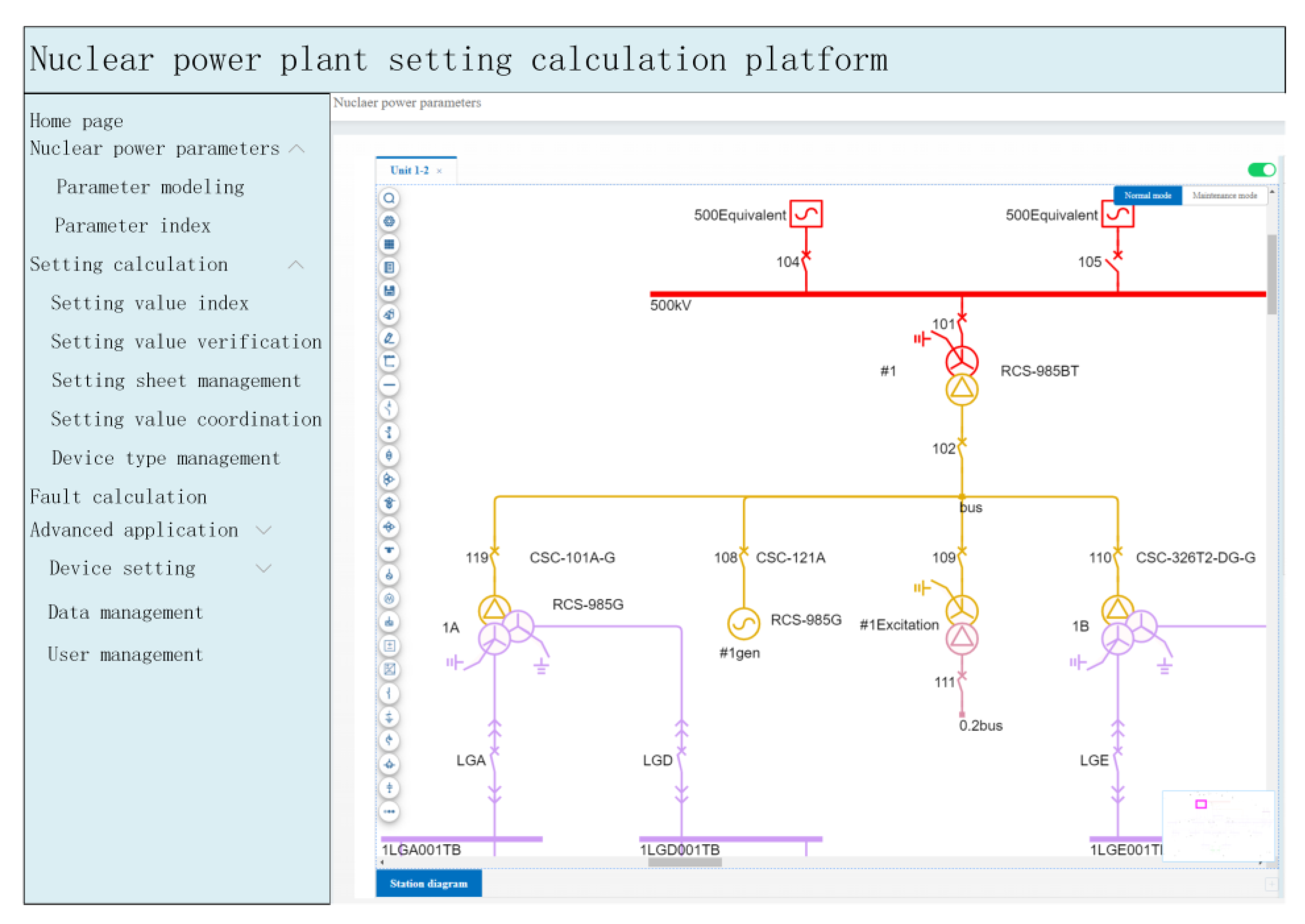
4.1. Relay Protection Setting Calculation Function of Nuclear Power Plant

The nuclear power plant setting calculation system mainly includes nuclear power modeling, parameter index, setting calculation, fault calculation, setting value verification, setting value index, calculation sheet management, device type management, advanced application, user management, and other functional modules; the setting calculation system adopts the node impedance analysis method, calculation curve algorithm, perfect relay protection device expert system, “device oriented” manual assistance and automatic setting technology, and automatic generation of data and information to solve the problems that are difficult to understand, start, and apply, which are common in other setting calculation systems, as shown in Figure 5. The system optimizes the user interface by using abundant shortcut tool menus and simplified right-click menus. With hierarchical modeling, it realizes the concrete connection between the Nuclear Power Group and nuclear power plants and the visual management of power plant equipment. The relay protection of nuclear power plants has high safety requirements, and there are strict requirements for the accuracy of the setting calculation. The system has carried out in-depth research on the verification function of setting values. Adopting the relay protection calculation setting value verification module of nuclear power plants, based on the calculation formula of setting values of nuclear power plants and the calculation results of various short-circuit currents, the setting calculation setting values are automatically verified, and a verification report is generated, which supports comparison with historical calculation reports and marking the difference to verify the accuracy of the setting value.

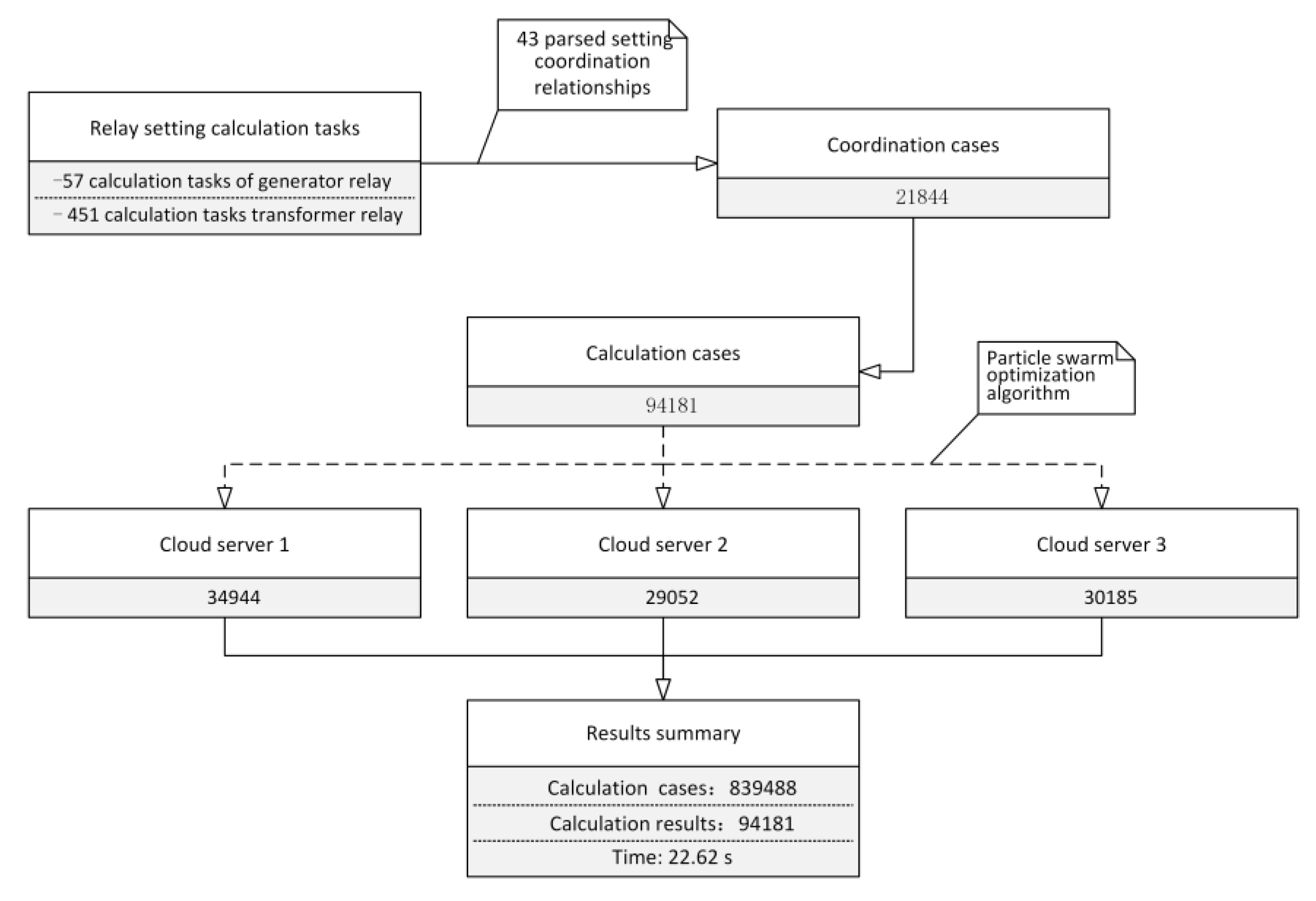
4.2. Calculation Efficiency of Relay Protection Setting in Nuclear Power Plants

There are six units in a nuclear power plant. Power units and transformers 1-4 have the same parameters. The rated capacity of the generator is 1250 MVA, and the rated active power is 1150MW. Each unit is electrically connected with two auxiliary transformers. The main primary equipment includes 4500 kV buses, 4500 kV outgoing lines, six generators with an outlet voltage of 24 kV, 6530/24 kV main transformers, 6220/6 kV auxiliary transformers, 624/6.9 kV double split high-voltage auxiliary transformers, 624/0.3 kV excitation transformers, 576.6/0.4 kV low-voltage auxiliary transformers, and 606.6 kV motors. The RCS-985 series is adopted as a relay protection device. The RCS-985G protection device is adopted for the generator and excitation transformer, the RCS-985BT protection device is adopted for the main transformer and HV auxiliary transformer, and the RCS-985FG is adopted for the non-electric parameter of the main transformer. The electrical connection of 1 #, 2 #, 3 #, and 4 # units is the same, and the electrical connection of 5 # and 6 # units is the same, as shown in Figure 6.
First, the system preprocesses the data of all equipment in the nuclear power plant and calls the parameter cloud component named “paraMaintain” and the calculation model cloud component named “Calcmodel” of the nuclear power plant to convert the grid parameter into an equivalent calculation model. After the main task of setting calculation is submitted to the task proxy server of the load balancer, it is distributed to the main server to call the setting calculation algorithm cloud component named “SetAdvApp” for task partitioning. The task-splitting process is as follows (Figure 7):
The main server partitions the main task of setting calculation into 451 calculation tasks of transformer relay and 57 calculation tasks of generator relay and sends them back to the task agent server; the task proxy server distributes all relay calculation tasks to 3 cloud servers applying the particle swarm optimization algorithm; each cloud server parses each calculation tasks into 43 setting coordination relationships (various setting rules for generator protection, main transformer protection, HV auxiliary transformer protection, and excitation transformer protection) and sends them back to the task agent server; the task proxy server distributes 21,844 coordination cases to 3 cloud servers applying the particle swarm optimization algorithm; each cloud server parses the coordination relationship into calculation cases and sends them back to the task proxy server; the task proxy server sends all 94,181 calculation cases to cloud servers according to the resource configuration and availability of each cloud server based on the particle swarm optimization algorithm. Server 1 receives 34,944 calculation cases, Server 2 receives 29,052 calculation cases, and Server 3 receives 30,185 calculation cases, as shown in Figure 7.
The cloud component management center automatically loads the calculation model cloud component named “Calcmodel” and the calculation algorithm cloud component named “FaultCalcCore” for each cloud server in the system preprocessing; the cloud servers receive the calculation case that has been parsed into the smallest granularity and calls the cloud algorithm component for parallel calculation; 839488 cases are calculated, which takes 22.62 s; after the calculation task is completed, the calculation results will be returned to the task proxy server of the load balancer, and then to the main server; the main server collects the total 94,181 calculation results of all subtasks and returns them to the task proxy server; the calculation results will be forwarded to the data storage proxy server at the same time and then broadcast to all online cloud servers for cloud storage, and then the cloud computing process is ended.
The number of calculation processes involved in the setting calculation system is adjusted from 1 to 50, and 10 typical processes are selected for test calculation. The calculation case and calculation process are the same as those in Section 4.2. The calculation time and acceleration ratio are shown in Table 1. The calculation formula of the acceleration ratio is shown in Formula 5. The acceleration ratio increases linearly with the number of processes and the degree of parallelism. When using a single computing process, it takes about 50 min. When 50 processes are provided, it takes only 22.62 s to complete the computing task with an acceleration ratio of 42.98. Considering the delay of task scheduling, this value is close to the theoretical optimal value.
Acceleration   ratio = S i n g l e   p r o c e s s   c o m p u t i n g   t i m e F u l l   p r o c e s s   o m p u t i n g   t i m e
Reference [42] describes a relay protection setting calculation system based on C/S architecture, which carries out off-line setting calculation for the most complex power grid operation and proposes grid calculation methods under various grid structures. The relay protection setting calculation system in reference [42] calculates the short circuit current of the whole network for the regional power grid with 1830 nodes, the calculation scheme is finally divided into 150 power supply schemes that are calculated in parallel, and the whole calculation process takes 18 min. In contrast, the relay protection setting calculation system designed in this paper, which is configured with 10 calculation processes, takes only 2.04 s to calculate the same scale of calculation cases, which has obvious efficiency advantages [42].

5. Conclusions

The relay protection setting calculation system of nuclear power plants based on B/S architecture and cloud computing is a platform for relay protection setting calculation and management of nuclear power plants. The practical application results show that the system has obvious technical advantages compared with the previous generation of setting calculation systems.
The system still has further research work to be carried out now, such as the application of the technology in a wider range of cloud platforms (the dispatching and control cloud), the technical exploration of real-time access to the setting calculation system applying wireless private networks and mobile terminals, and more application of artificial intelligence technology in the setting calculation business, so as to achieve the optimal automatic protection setting. The highly intelligent relay protection setting calculation system of the nuclear power plant will promote a change in the main task of setting calculation engineers from setting value calculation to setting value management.

Author Contributions

Conceptualization, Y.H., Y.Y. and J.T.; Data curation, W.Y.; Investigation, Y.H. and W.Y.; Methodology, Y.Y.; Project administration, Y.H.; Resources, Y.Y. and J.T.; Software, J.T.; Writing—original draft, H.Y.; Writing—review & editing, B.W. All authors have read and agreed to the published version of the manuscript.

Funding

This research was funded by the National Natural Science Foundation of China under Grant 52077116.

Acknowledgments

The authors gratefully acknowledge the support of Dejia LI and Xin Wang of Nuclear Power Operations Research Institute, Shanghai 201208, China, for their comments in developing this study.

Conflicts of Interest

The authors declare no conflict of interest.

References

  1. Wang, Y.Z.; Zhou, S. Comprehensive assessment of the environmental impact of China’s nuclear and other power generation technologies. J. Tsinghua Univ. Sci. Technol. 2021, 61, 377–384. [Google Scholar]
  2. Wu, H.S.; Wang, H.D. Present situation of world nuclear power. News Oversea Nucl. 2011, 1, 7–10. (In Chinese) [Google Scholar]
  3. Ye, Q.Z. China’s nuclear power development after Fukushima nuclear power plant accident. In Proceedings of the IEEE Conference on Software Engineering Education and Training, Nanjing, China, 17–19 April 2012; Volume 32, pp. 1–8. (In Chinese). [Google Scholar]
  4. Wu, P.; Yang, Y.C. Research on Operational Characteristics and Core Simulation of the Third-Generation Nuclear Reactor AP1000. Power Syst. Technol. 2014, 38, 1196–1202. [Google Scholar]
  5. Maldonado, G.I. The performance of North American nuclear power plants during the electric power blackout of August 14, 2003, In IEEE Symposium Conference Record Nuclear Science 2004, Proceedings of the IEEE Symposium on Nuclear Science (NSS/MIC), Rome, Italy, 16–22 October 2004; IEEE: Piscataway, NJ, USA, 2004. [Google Scholar]
  6. Ma, J.P.; Jiang, J. Applications of fault detection and diagnosis methods in nuclear power plants: A review. Nucl. Energy 2011, 53, 255–266. [Google Scholar] [CrossRef]
  7. Eom, H.-S.; Park, G.-Y. V&V-based remaining fault estimation model for safety–critical software of a nuclear power plant. Nucl. Energy 2013, 51, 38–49. [Google Scholar]
  8. Yang, F.; Zhao, D.M. Research of relay protection setting calculation system for power plant based on Multi-agent. In Proceedings of the 2010 Asia-Pacific Power and Energy Engineering Conference, Chengdu, China, 28–31 March 2010. [Google Scholar]
  9. Andreev, M.; Gusev, A. Setting of relay protection of electric power systems using its mathematical models. In Proceedings of the 2017 IEEE PES Innovative Smart Grid Technologies Conference Europe (ISGT-Europe), Turin, Italy, 26–29 September 2017. [Google Scholar]
  10. Roman, V.; Klyuev, I.; Bosikov, I. Improving the efficiency of relay protection at a mining and processing plant. J. Min. Inst. 2021, 248, 300–311. [Google Scholar]
  11. Chang, C.-K.; Elmashtoly, A.M. Protection Coordination Index Assessment Using Fuzzy Logic Controller. Energies 2022, 15, 1377. [Google Scholar] [CrossRef]
  12. Lu, Y.; Chung, J.-L. Detecting and solving the coordination curve intersection problem of overcurrent relays in subtransmission systems with a new method. Electr. Power Syst. Res. 2013, 95, 19–27. [Google Scholar] [CrossRef]
  13. Bouchekara, H.; Zellagui, M.; Abido, M.; Bouchekara, H.R.E.-H. Optimal coordination of directional overcurrent relays using a modified electromagnetic field optimization algorithm. Appl. Soft Comput. 2017, 54, 267–283. [Google Scholar] [CrossRef]
  14. Zeineldin, H.H.; Sharaf, H.M.; Ibrahim, D.K.; El-Zahab, E.E.D.A. Optimal Protection Coordination for Meshed Distribution Systems with DG Using Dual Setting Directional Over-Current Relays. IEEE Trans. Smart Grid 2015, 6, 115–123. [Google Scholar] [CrossRef]
  15. Prenc, R.; Rojnić, M. On the Development of Overcurrent Relay Optimization Problem for Active Distribution Networks. Energies 2022, 15, 6528. [Google Scholar] [CrossRef]
  16. Li, D. Relay Coordination and Setting Management Integrated System Based on Hybrid Architecture. Master’s Thesis, Huazhong University of Science and Technology, Wuhan, China, April 2006. [Google Scholar]
  17. Jie, Z. Protection Coordination Software for Distribution Networks Based on C/S. Master’s Thesis, Huazhong University of Science and Technology, Wuhan, China, May 2003. [Google Scholar]
  18. Liu, Q.; Chen, S. Object-Oriented methods drive protective relay system. IEEE Comput. Appl. Power 2000, 14, 33–37. [Google Scholar]
  19. Zhang, J.P.; Zhu, X.D.; Liang, X. C/S and B/S Mixed Style and the Application. In Proceedings of the 2009 First International Workshop on Education Technology and Computer Science, Wuhan, China, 7–8 March 2009. [Google Scholar]
  20. Yang, A.; Wu, J.; Wang, L. Research and Design of Test Question Database Management System Based on the Three-Tier Structure. WSEAS Trans. Syst. 2008, 7, 1473–1483. [Google Scholar]
  21. Wang, L. Research of Geological Exploration Information System Based on Three-tiered C/S Architecture. Adv. Mater. Res. 2012, 490–495, 2942–2945. [Google Scholar] [CrossRef]
  22. Wan, C.T.; Ling, W.W. Three-tier Multi-Agent Architecture for Asset Management Consultant. In Proceedings of the 2004 IEEE International Conference on e-Technology, e-Commerce and e-Service, Taipei, Taiwan, 28–31 March 2004. [Google Scholar]
  23. Nuclear Power Engineering Committee of the IEEE Power Engineering Society. IEEE Standard Criteria for Digital Computers in Safety Systems of Nuclear Power Generating Stations; IEEE: Piscataway, NJ, USA, 1993. [Google Scholar]
  24. Hu, S.; Xiao, Y. Design of cloud computing task offloading algorithm based ondynamic multi-objective evolution. Future Gener. Comput. Syst. 2021, 122, 144–148. [Google Scholar] [CrossRef]
  25. Alla, H.B.; Alla, S.B.; Touhafi, A.; Ezzati, A. A novel task scheduling approach based on dynamic queues and hybrid meta-heuristic algorithms for cloud computing environment. Clust. Comput. 2018, 21, 1797–1820. [Google Scholar] [CrossRef]
  26. Sreenu, K.; Malempati, S. MFGMTS: Epsilon constraint-based modified fractional grey wolf optimizer for multi-objective task scheduling in cloud computing. IETE J. Res. 2019, 65, 201–215. [Google Scholar] [CrossRef]
  27. Aziza, H.; Krichen, S. Bi-objective decision support system for taskscheduling based on genetic algorithm in cloud computing. Computing 2018, 100, 65–91. [Google Scholar] [CrossRef]
  28. Agarwal, A.; Jain, S. Efficient optimal algorithm of task-scheduling in cloud computing environment. Int. J. Comput. Trends Technol. 2014, 9, 344–349. [Google Scholar] [CrossRef] [Green Version]
  29. Sim, K.M.; Sun, W.H. Ant Colony Optimization for Routing and Load-Balancing Survey and New Directions. Syst. Man Cybern. Part A Syst. Hum. 2003, 33, 560–572. [Google Scholar]
  30. Simone, A.; Ludwig, A.M. Swarm Intelligence Approaches for Grid Load Balancing. Grid Comput. 2011, 9, 279–301. [Google Scholar]
  31. Chow, K.P.; Rwok, Y.K. On load balancing for distributed multi-agent computing. IEEE Trans. Parallel Distrib. Syst. 2002, 13, 787–801. [Google Scholar] [CrossRef]
  32. Mapetu, J.P.B.; Chen, Z.; Kong, L.F. Low-time complexity and low-cost binary particle swarm optimization algorithm for task scheduling and load balancing in cloud computing. Appl. Intell. 2019, 43, 3308–3330. [Google Scholar] [CrossRef]
  33. Ramezani, F.; Jie, L.; Hussain, K.F. Task-based system load balancing in cloud computing using particle swarm optimization. Int. J. Parallel Prog. 2014, 42, 739–754. [Google Scholar] [CrossRef]
  34. Pandey, S.; Wu, L.; Guru, S.M.; Buyya, R. A Particle swarm optimization-based heuristic for scheduling workflow applications in cloud computing environments. In Proceedings of the 24th IEEE International Conference on Advanced Information Networking and Applications, Perth, Australia, 20–23 April 2010; pp. 400–407. [Google Scholar] [CrossRef]
  35. Valarmathi, R.; Sheela, T. A comprehensive survey on task scheduling for parallel workloads based on particle swarm optimization under cloud environment. In Proceedings of the 2nd International Conference on Computing and Communications Technologies (ICCCT), Chennai, India, 23–24 February 2017; pp. 81–86. [Google Scholar] [CrossRef]
  36. Boetinser, D.W.; Wemer, D.H. Particle swarm Optimization Versus Cenetic Algonithms for Phased Artay synthesis. Antennas Propag. 2004, 52, 711–779. [Google Scholar]
  37. Wadood, A.; Kim, C.-H. Application of a Continuous Particle Swarm Optimization (CPSO) for the Optimal Coordination of Overcurrent Relays Considering a Penalty Method. Energies 2018, 11, 869. [Google Scholar] [CrossRef] [Green Version]
  38. Zeineldin, H.H.; El-Saadany, E.F.; Salama, M.M.A. Optimal coordination of overcurrent relays using a modified particle swarm optimization. Electr. Power Syst. Res. 2006, 76, 988–995. [Google Scholar] [CrossRef]
  39. Antonio, J.; Medeiros, C.C.; Schirru, R. Identification of nuclear power plant transients using the particle swarm optimization algorithm. Ann. Nucl. Energy 2008, 35, 576–582. [Google Scholar]
  40. Mansour, M.M.; Mekhamer, S.F.; El-Kharbawe, N. A modified particle swarm optimizer for the coordination of directional overcurrent relays. IEEE Trans. Power Deliv. 2007, 22, 1400–1410. [Google Scholar] [CrossRef]
  41. Park, J.B.; Lee, K.S.; Shin, J.R.; Lee, K.Y. A particle swarm optimization for economic dispatch with nonsmooth cost functions. IEEE Trans. Power Syst. 2005, 20, 34–42. [Google Scholar] [CrossRef]
  42. Liu, G.P. Research on on-line Setting and Assessment Early Warning of Relay Protection in Regional Grid. Doctoral Dissertation, North China Electric Power University, Beijing, China, June 2013. [Google Scholar]
Figure 1. Architecture comparison diagram.
Energies 15 09648 g001
Figure 2. Relay Protection Setting Calculation System Framework Diagram of Nuclear Power Plant.
Energies 15 09648 g002
Figure 3. Cloud setting computing task processing topology diagram.
Energies 15 09648 g003
Figure 4. Setting cloud components organization chart.
Energies 15 09648 g004
Figure 5. Setting calculation functional architecture.
Energies 15 09648 g005
Figure 6. Nuclear power plant parameter modeling.
Energies 15 09648 g006
Figure 7. Setting calculation case of nuclear power plant.
Energies 15 09648 g007
Table 1. Calculation efficiency comparison.
Processes NumberCalculation Time/sAcceleration Ratio
11089.151.00
2553.431.97
5220.484.94
10110.499.86
1574.7814.56
2056.7619.19
2548.1422.62
3041.0926.51
4030.8135.35
5022.6242.98
Publisher’s Note: MDPI stays neutral with regard to jurisdictional claims in published maps and institutional affiliations.

