1. Introduction
Recently, regulations on carbon emissions due to environmental problems are being implemented around the world. In the automotive sector, regulations on internal combustion engine vehicles are in place and the production of internal combustion engine vehicles will cease within the next 10 years. Accordingly, the development of fuel cell electric vehicles (FCEVs) and electric vehicles is actively progressing. Electric vehicles have longer charge times and have lower driving ranges than internal combustion engine vehicles. Research has been conducted in many areas to shorten charging times and increase driving range. Research is underway on high torque, high efficiency, and high power density electric motors for driving EVs [
1,
2,
3,
4].
There are three types of motors used to drive electric vehicles: interior permanent magnet synchronous motor (IPMSM), induction motor (IM), and wound field synchronous motor (WFSM). IPMSM has the characteristics of high efficiency and high power density among the other types motors. However, there is a limit to increasing the maximum speed because the magnetic flux cannot be controlled. On the other hand, the wound field synchronous motor can have a wide field-weakening area because it can control the field flux, but it has lower efficiencies compared to the interior permanent magnet synchronous motor due to a loss of copper during field winding [
5,
6]. IPMSM uses a graded permanent magnet with high residual magnetic flux density to output high torques at the rated point. If a high-grade permanent magnet is used in the same battery, the speed limit point appears at a lower speed due to the high back electromotive force.
Figure 1 shows the vector diagram of a permanent magnet synchronous motor. In a permanent magnet, the flux linkage in the stator windings occurs along the positive d-axis. The applied current is located in the second quadrant and meets the inductance of the winding to generate d- and q-axis magnetomotive force. The stator magnetomotive force determines the armature flux linkages. As the motor rotates, the flux linkage vector considering the rotational speed is shown in the second quadrant region, which is 90 degrees ahead. The induced voltage caused by the armature flux linkage and the voltage drop of the windings is added to create the phase voltage of the motor. To lower the phase voltage, the induced voltage must be reduced. To lower the induced voltage, the d-axis magnetomotive force must be increased. The d-axis magnetomotive force is a demagnetizing magnetism, which weakens the flux linkage from the permanent magnet to the stator winding.
In order to increase the rotation speed of the motor, the inverter controls the d-axis current that generates demagnetizing forces and the q-axis current that generates torque. The angle between the applied current and the q-axis current is called the current phase angle, and when the current phase angle is 90 degrees, only the d-axis current is applied, and no torque is generated. As such, there is a limit to the speed increase in a controllable manner.
An internal combustion engine vehicle uses a transmission to increase the speed of the engine. However, electric vehicles do not use a transmission and increase the speed of the motor only by controlling the inverter. There are studies that increase the speed of electric vehicles by using an electromagnetic method without using mechanical transmissions. There are studies that increase the speed by changing the electrical frequency and by changing the number of poles in the IM. The IPMSM also increases the maximum speed by changing the number of poles of the stator from 8 to 4 to increase the speed. At the same time, it reduces the core loss and increases the efficiency of the motor [
7]. Further research demagnetizes the permanent magnet at the point of a maximum velocity of four poles after converting the number of poles from 8 poles to 4 poles to further increase the maximum speed. At this time, the number of poles is demagnetized using the stator current while maintaining four poles [
8,
9,
10,
11,
12,
13].
Another study examined how to vary the number of series turns of the stator windings [
14]. To use this method, separate circuits were used for half of the windings and the remaining windings were examined for the total number of series turns. If the number of series turns of the motor is high, the back electromotive force also increases as the speed increases, so it is difficult to increase it beyond a certain speed [
15]. By reducing the number of series turns via the switching element at a constant speed, the back electromotive force is lowered. It has the advantage of increasing the speed by using a small number of switching elements [
16].
There are studies to secure a large starting torque and a wide field-weakening area for high-speed operations that are required by electric vehicle systems [
17]. In the same way as IM’s wye-delta method, it is driven by wye connections in the low-speed range to secure torque to increase acceleration and climbing abilities. The characteristic of the wye connection is that the phase voltage and the line voltage differ by 1.73 times. The characteristic of the delta connection is that the phase voltage and the line voltage are the same. Comparing the back electromotive force at the same speed, in the case of the back electromotive force of the wye connection, two phase back electromotive forces appear as back electromotive forces between the lines, and in the back electromotive force of the delta connection, the back electromotive force corresponding to one phase appears as the back EMF between the lines. Therefore, it is a method for changing to a delta connection in order to satisfy high torques by using high back electromotive force at low speeds and can be used to lower back electromotive forces in high-speed regions [
18].
In this paper, we introduce a method to increase torque, efficiency, and speed in the low-speed range of EV-driven IPMSMs using an electromagnetic multi-step transmission. As the speed of the motor increases, the back electromotive force also increases, reaching a faster operating limit. In order to improve the high speed and high torque characteristics of the PM motor, the number of parallel paths of the stator windings was changed to reach high torque at low speeds and to expand the high-speed region. The method of changing the number of stator parallel paths uses a thyristor. A comparison of the losses in the change in the speed process when using IGBTs and when using thyristors shows similar results. Therefore, a cheaper thyristor was used. In order to select a change in the speed point, an analysis is performed by applying the number of stator parallel paths selected before the change in speed. After that, the analysis proceeds by applying the number of parallel paths after the change in speed. The voltage characteristics in both cases are derived via an analysis, and the voltage saturation point is selected as the change in speed point. The high efficiency region expansion is also achieved via the transmission system. In order to analyze the effectiveness, the analysis is carried out using finite-element-method-based simulations.
2. Electromagnetic Characterization for Electromagnetic Multi-Step Transmission Applications
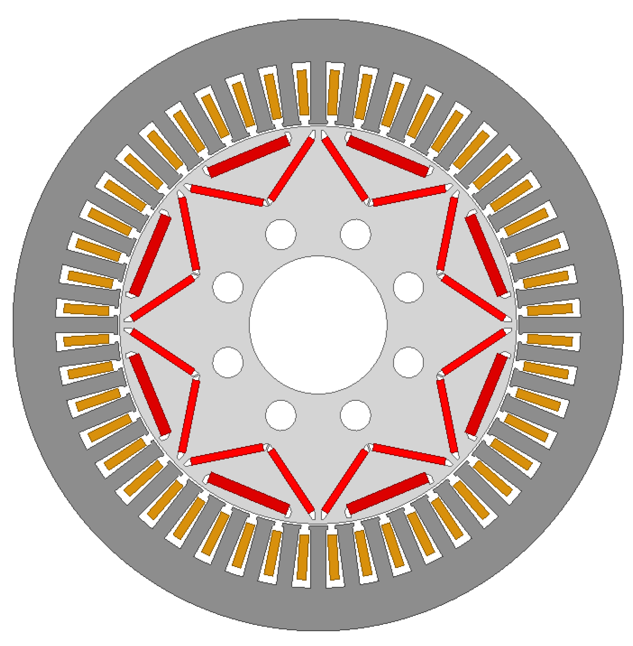
Figure 2 shows the shape of a motor for driving an EV with 8 poles and 48 slots.
Table 1 shows the specifications of the 80 (kW) IPMSM. Permanent magnets are arranged in a delta shape to concentrate the magnetic flux. The output is 80 kW, and the maximum torque is 254.65 Nm. Before change in speed, the number of parallel paths is two, and after change in speed, the number of parallel paths is four. Before applying the multi-step transmission, the electromagnetic characteristics of the two models were analyzed to select the change in speed points.
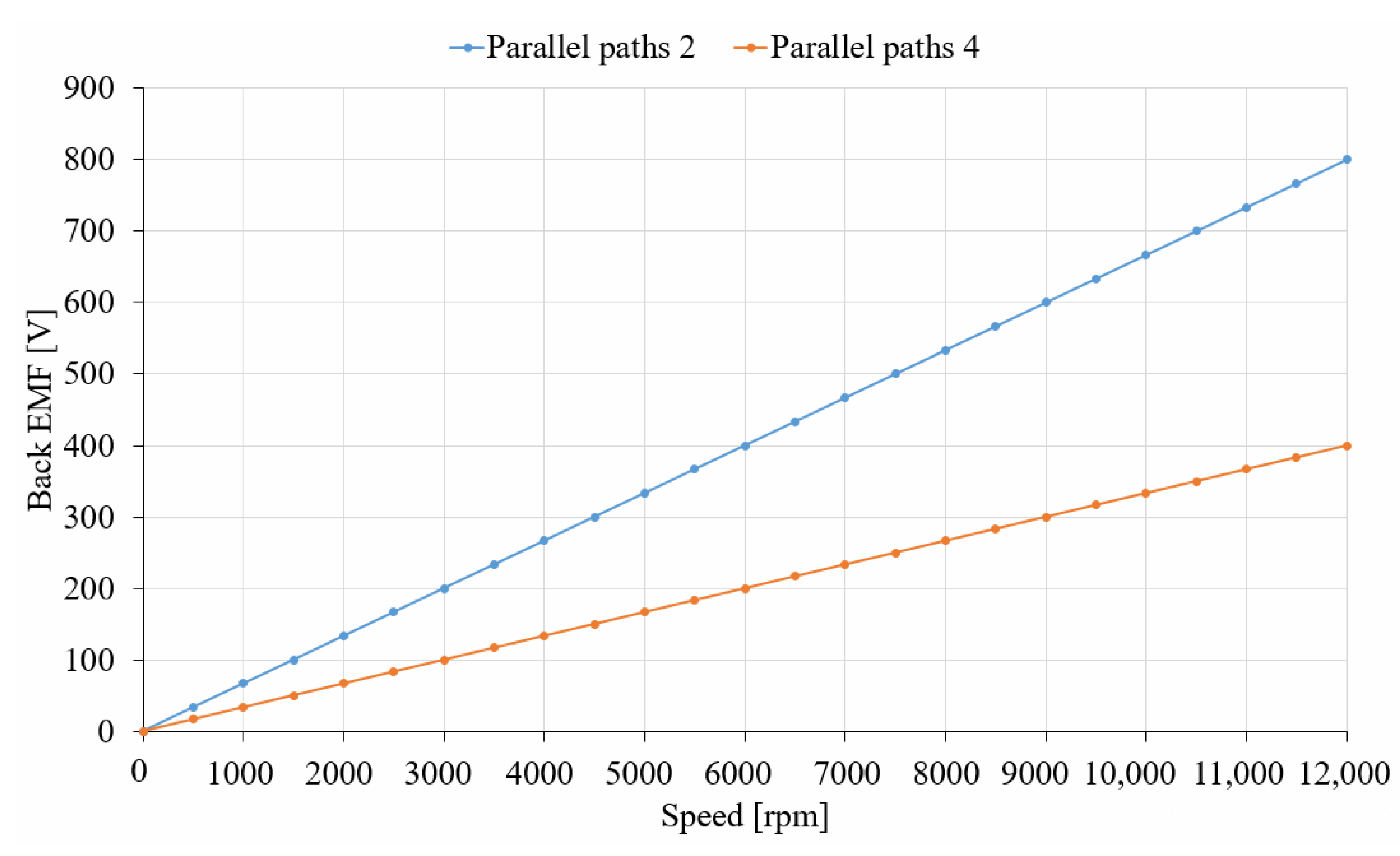
Before analyzing the operating characteristics of parallel path 2 and parallel path 4, a back electromotive force analysis was performed to select the base speed of the number of parallel paths: 4. The battery voltage of the system to which this model is applied to is a 300 Volt system.
Figure 3 shows the back electromotive force according to the speed for parallel path 2 and 4. When the number of parallel paths is two, the base speed is 3000 rpm, and the back electromotive force at this speed is 200 V
dc. For the base speed where there are four parallel paths, a speed having the same value as the back electromotive force in the base speed of the model in parallel path 2 was selected as the base speed. The base speed selected via the back electromotive force analysis according to the speed of the model with the number of parallel paths is 6000 rpm.
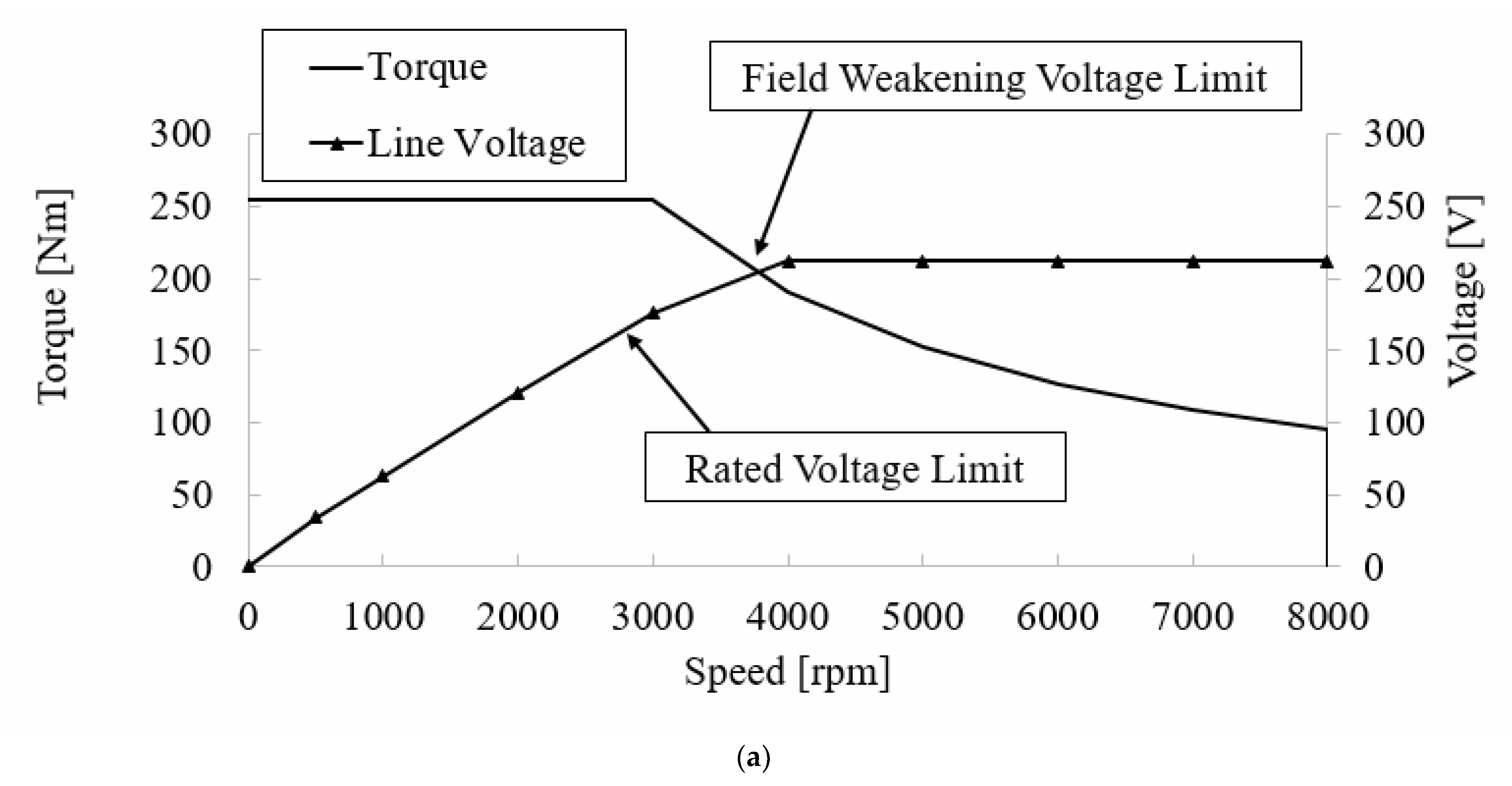
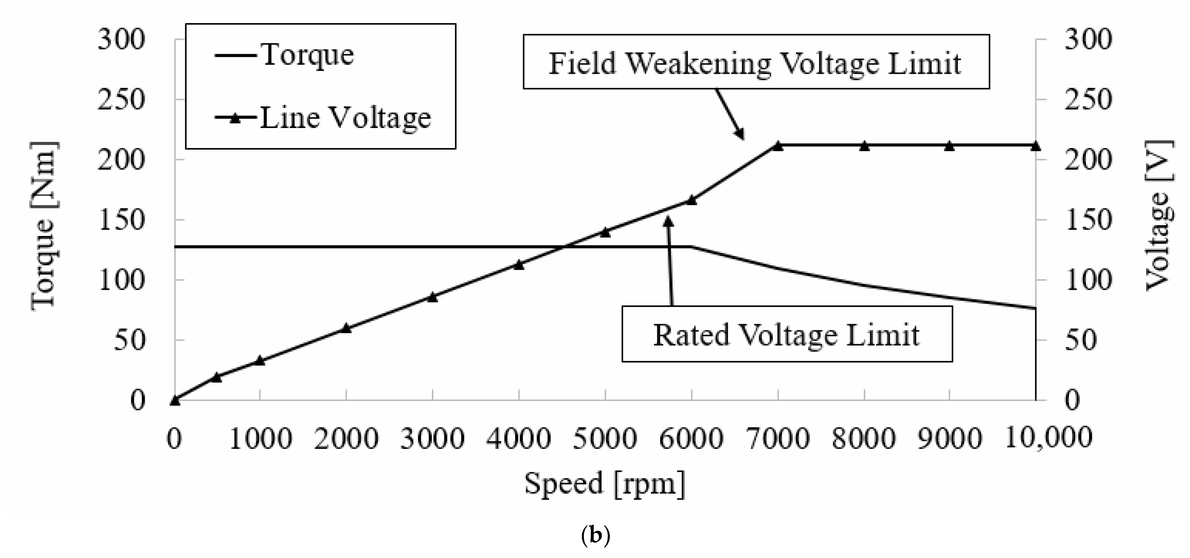
To analyze the operating range of parallel path 4, the maximum speed point was derived. The output is the same as the output of parallel path 2 and the torque at base speed is 127.3 Nm. The maximum speed derived from the analysis is 10,000 rpm.
Figure 4 shows the torque curve and voltage curve according to the speed for parallel paths 2 and 4. The voltage saturation point of the model with two parallel paths is at 4000 rpm, and the voltage saturation point of the model with four parallel paths is at 7000 rpm.
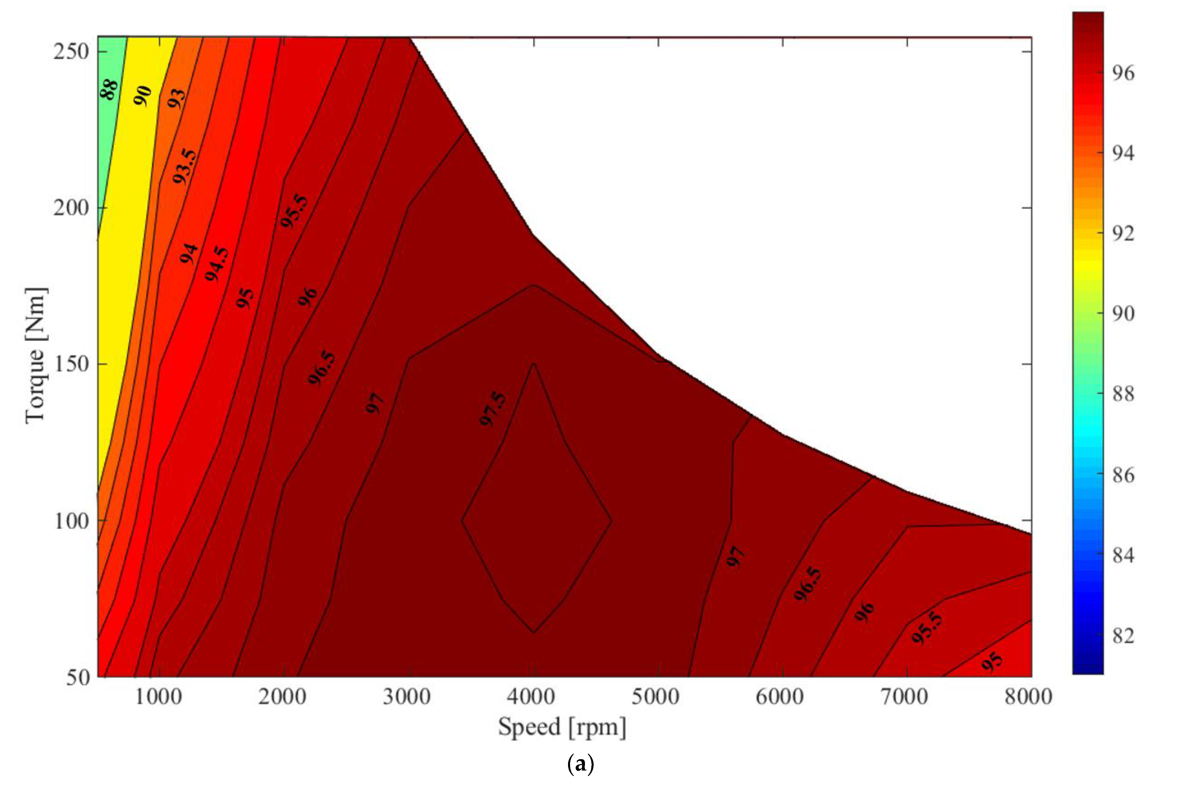
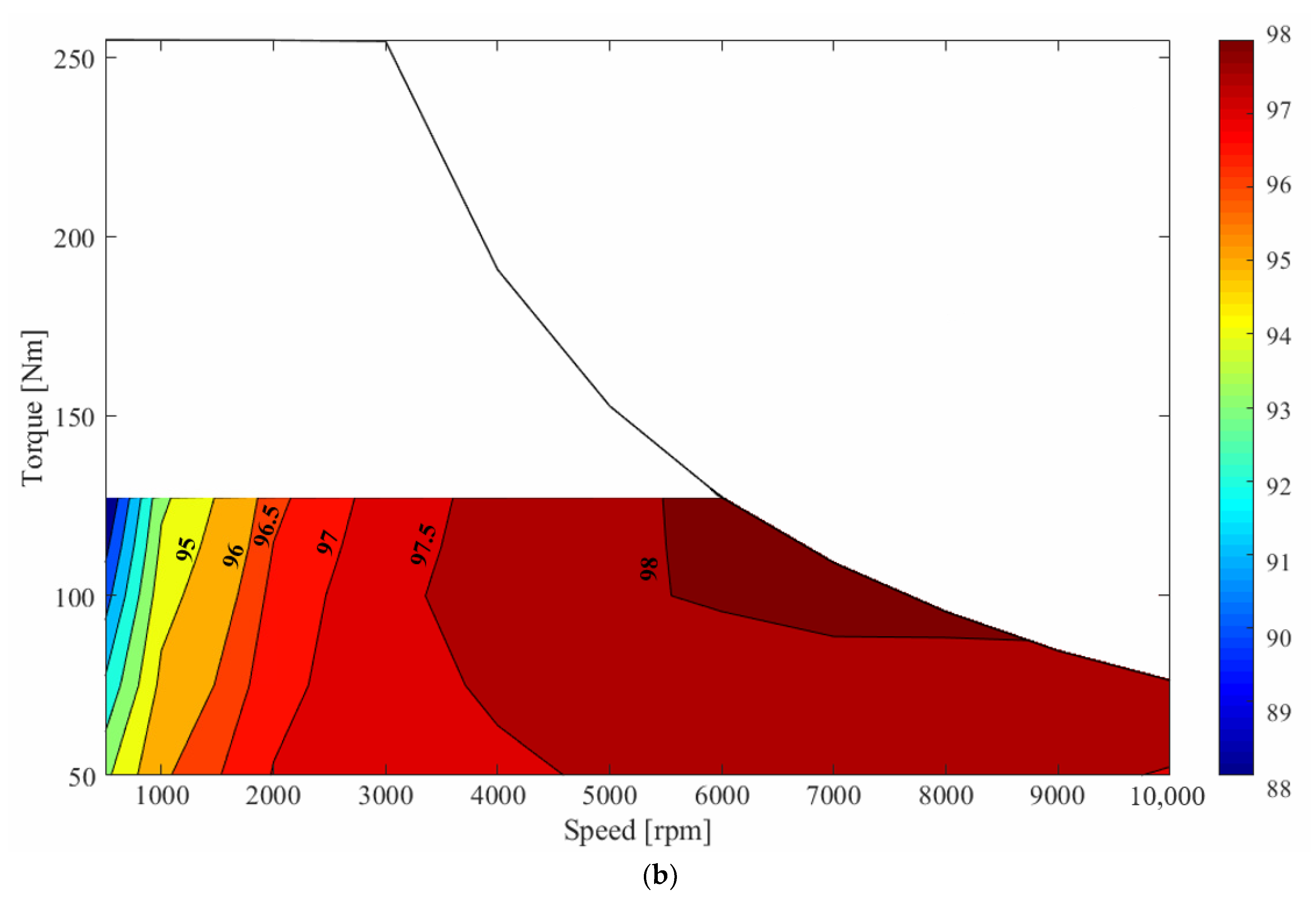
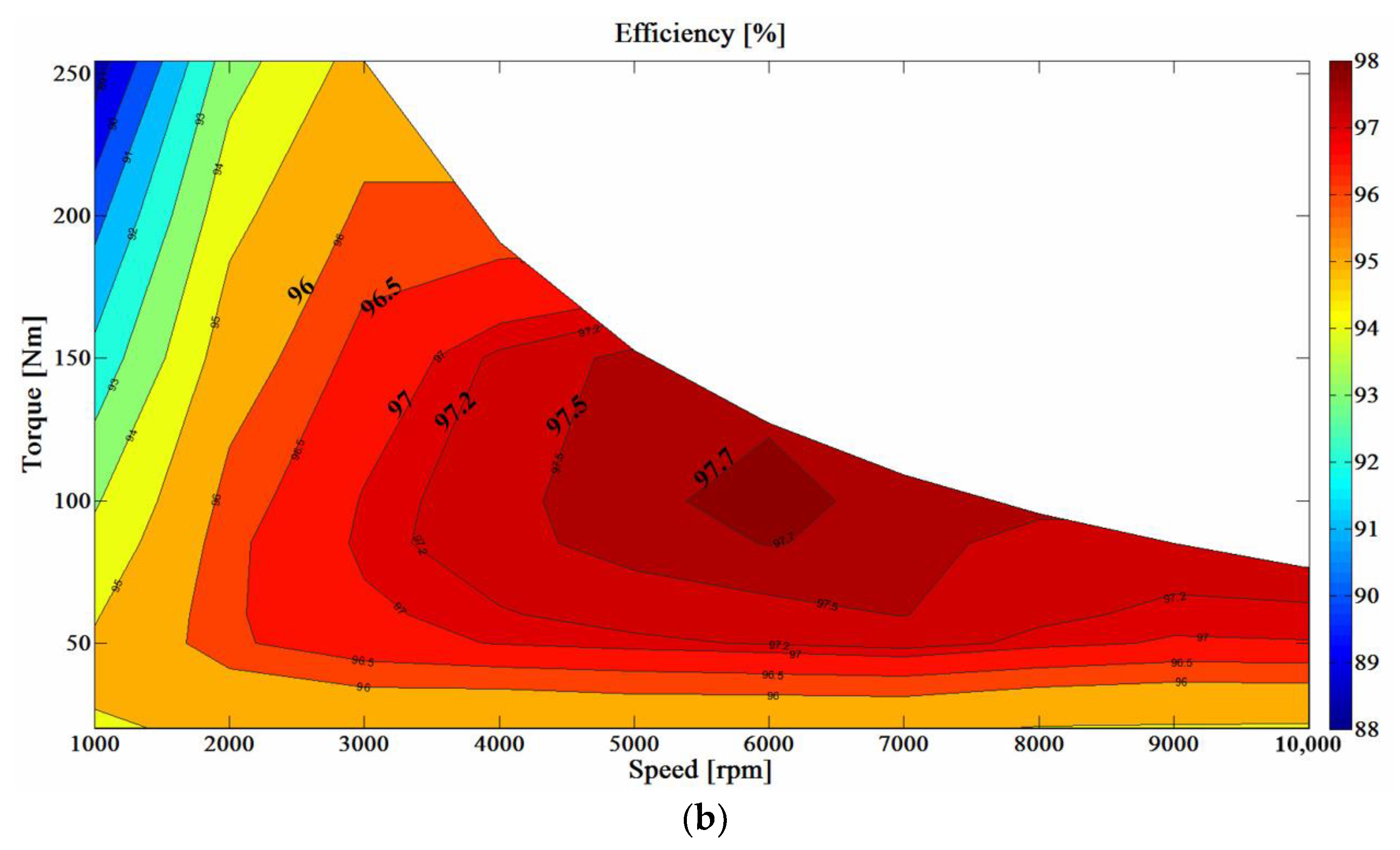
Figure 5 shows the efficiency characteristics of the parallel path 2 and 4 models. As a result of comparing the voltage saturation characteristic and the efficiency characteristic, the maximum efficiency point appears in the speed region where voltage saturation begins.
3. The Principle of Electromagnetic Multi-Step Transmissions
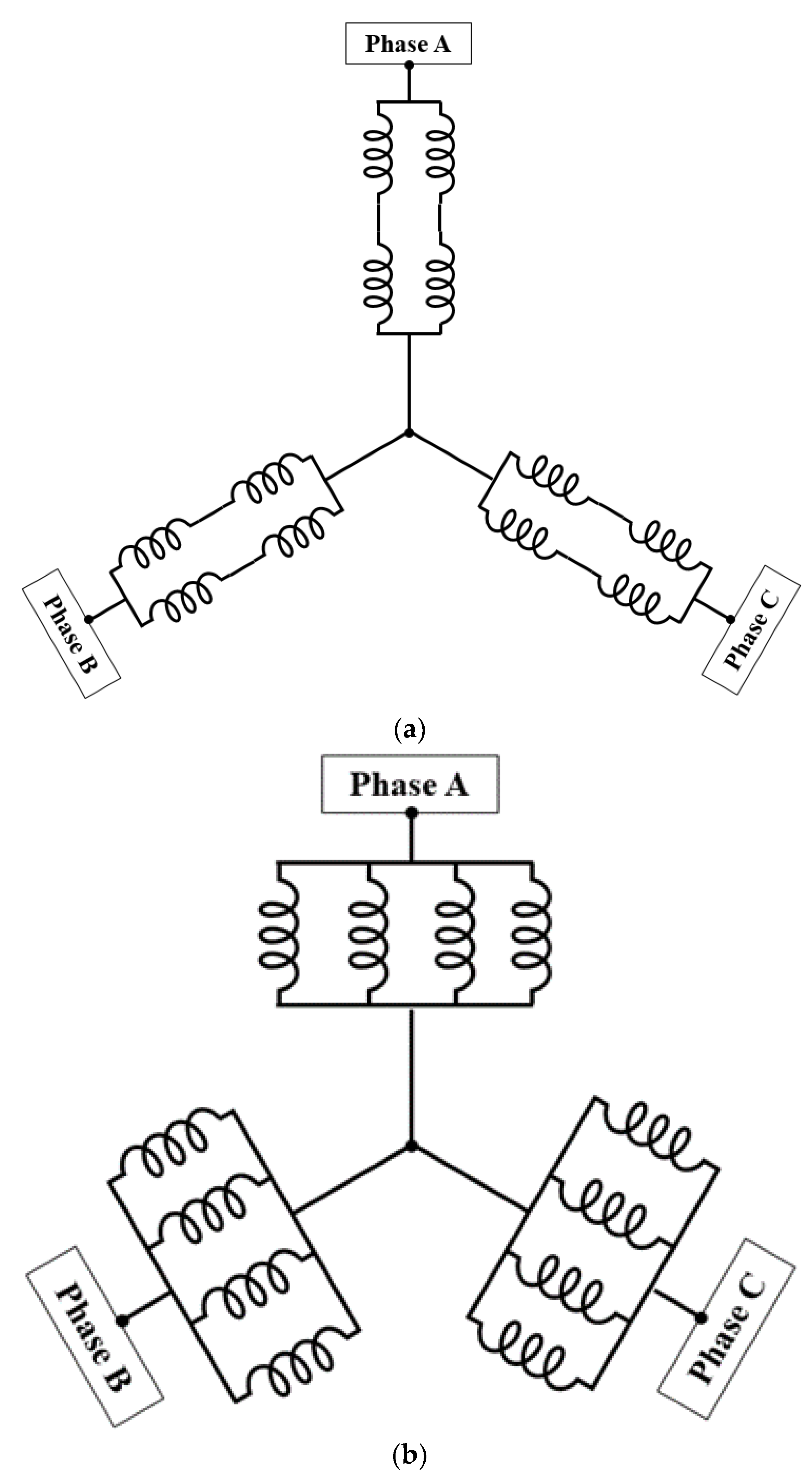
The electromagnetic multi-step proposed in this paper comprises a method of changing the number of parallel paths at a rated speed. The maximum number of parallel paths applicable is proportional to the number of pole pairs. The model for applying the electromagnetic multi-step transmission has four pole pairs, so the maximum number of parallel paths that can be applied is four. When the same current is applied, the model with two parallel paths has high torque at low speeds compared to the model with four parallel paths. At the same speed, the model with four parallel paths had a lower back electromotive force than the model with two parallel paths. Therefore, the maximum operable speed of the model with four parallel paths is higher than the model with two parallel paths. Using the advantages of both models, the high torque requirement is satisfied at low speeds and the speed region increased.
Figure 6 shows the series and parallel structure of the windings before and after electromagnetic multi-step applications. In the low-speed region, it operates with the winding structure as shown in
Figure 6a, and in the high-speed region after a change in speed, it operates with the winding structure, as shown in
Figure 6b. A switching circuit is used to change the number of parallel paths. The switch element for the change in speed uses a thyristor.
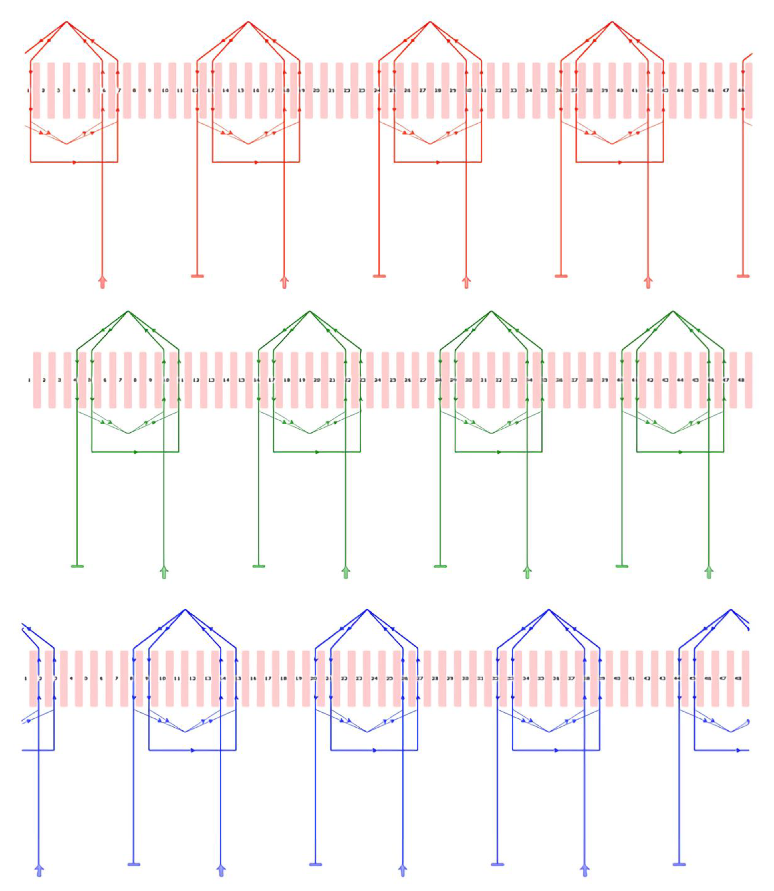
Figure 7 shows the stator winding diagram for each phase.
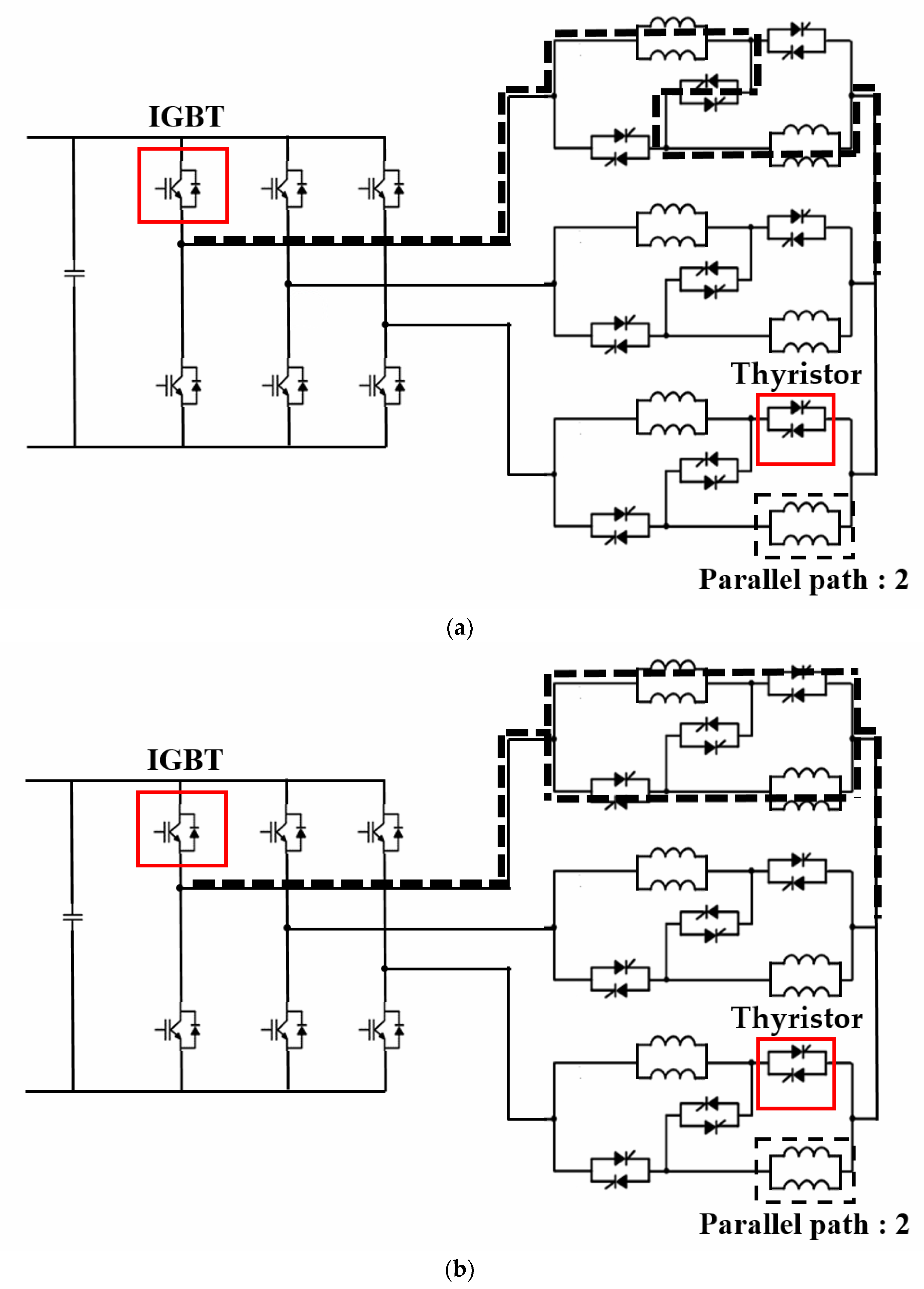
Figure 8 shows the circuit diagram and current flow for electromagnetic multi-step transmissions. Three thyristors are used for changing speeds in a circuit corresponding to one phase.
Figure 8a is a circuit diagram before changing the speed, and it operates with two parallel paths. In this case, only one thyristor per phase is used. In the process of changing speed, the thyristor used before changing speed opens, and the remaining two thyristors are shortened to divide the series-connected circuit in parallel.
Figure 8b shows the circuit after changing the speed, and it operates with four parallel paths.
In addition, compared to the case of the first shifting step, the range of motion expanded in order to expand the efficiency of the high-speed range and the range of maximum efficiency. The improved characteristics are shown in
Figure 6.
4. Application of 80 kW IPMSM Electromagnetic Multi-Step Transmission
After analyzing parallel path number 2 and 4 models, the time of the electromagnetic multi-step application is selected. Previously, with respect to the base speed of the model with four parallel paths, a speed with the same back electromotive force value as the back electromotive force of the model with two parallel paths was selected. The change in speed points was selected as the rated speed point of the parallel path 4 model.
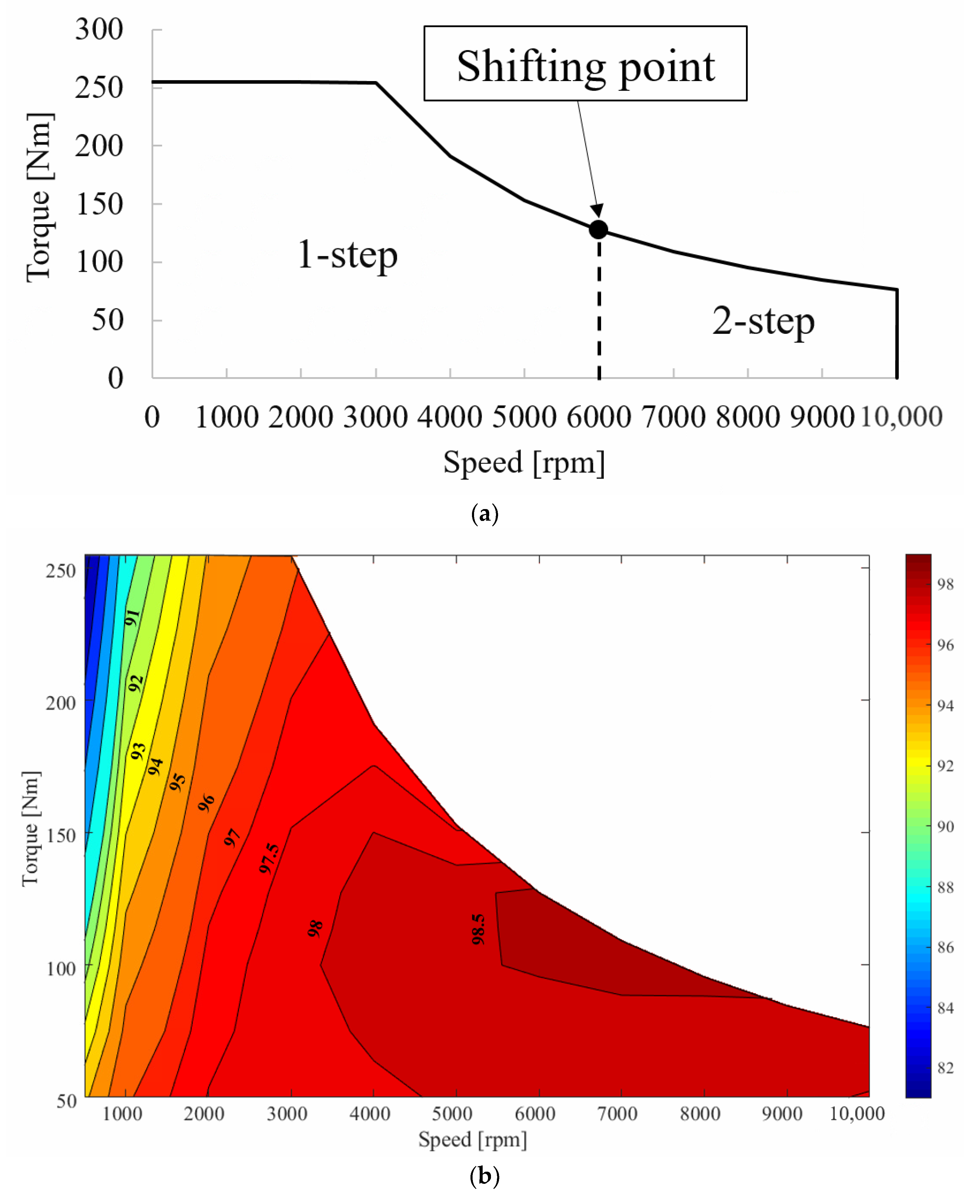
Figure 9 shows the speed torque curve and efficiency characteristics applied with electromagnetic multi-step transmissions. By applying electromagnetic multi-step transmissions, the operating range increased while securing a wide range of constant power. As the number of parallel paths increases, resistance decreases inversely. Copper loss accounts for the largest proportion of electromagnetic losses in motors. Copper loss is proportional to resistance, and as the resistance decreases, copper losses also decrease. Therefore, the high efficiency region in the high-speed region also increased by using the high efficiency region of the parallel path 4 model after changing its speed.
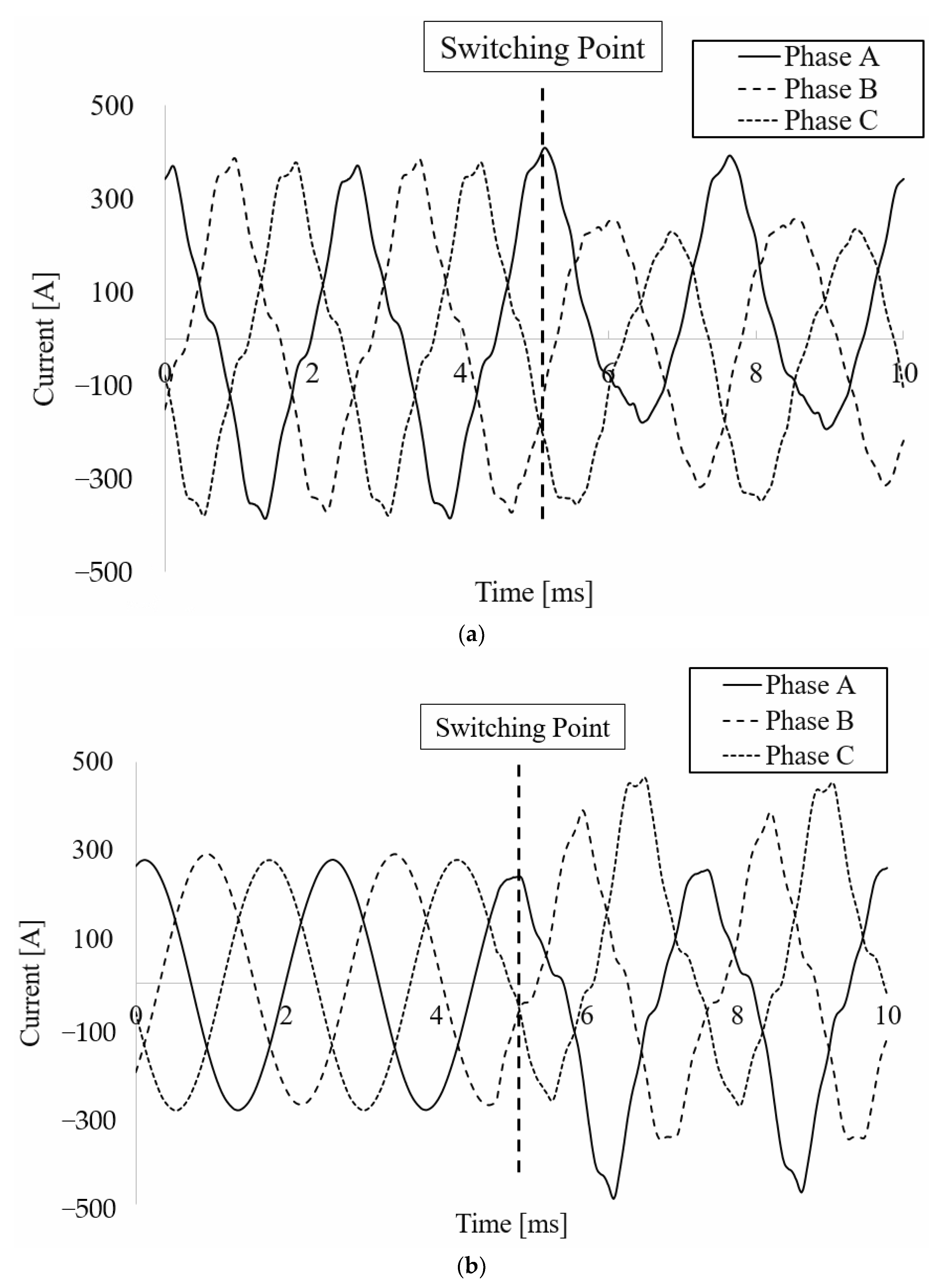
Figure 10 shows the waveform of the current appearing during the change in speed processes, which was analyzed via a simulation. During the change in speed, the inductance changes as the number of parallel paths moving through the switch changes. This causes transients and changes in the magnitude of the current. Before the change in speed, the three phases are the same, but they have the same size; however, after the change in speed, the current waveform appears to be unbalanced.
Figure 11 shows the parameters for inductance calculation. The parallel path changes during the change in speeds, and accordingly, the number of turns in series per phase changes, affecting the air gap component with respect to self-inductance. The number of turns in series per phase is given by
where
is the number of turns per pole,
p is the number of pole pairs, and
a is the number of parallel paths. The air gap component of self-inductance is given by
where
represents the magnetic flux per pole. Another inductance component, slot leakage inductance, is given by
where
is the number of magnet,
is the number of turns,
is the relative permeability, and
is stack length and another parameter of Equation (3) is defined in
Figure 10.
Finally, the phase self-inductance is given by
where
is the end-turn component.
In the 2D FEM analysis, the end turn self-inductance term was excluded. As a result, if the number of parallel paths in the same winding pattern is small, then the number of both turns in series per phase and the air gap component with respect to self-inductance is large. In other words, two parallel paths have higher inductances than four parallel paths.
However, as the tooths width increases, the area of the slot decreases. If the slot area decreases with the same winding size and number of turns, then the fill factor increases. As the fill factor increases, the slot leakage flux decreases. Therefore, both the air gap and slot leakage components must be considered.
5. Electromagnetic Analysis and Testing in the Process of Changing Speeds
Figure 12 shows the torque waveform that appears during the process of changing speeds. The unbalanced current affects the magnetic flux and ultimately the torque. The torque waveform is analyzed in order to analyze the impact on the motor when an imbalance occurs during the process of changing speeds. Because the current generates magnetic fluxes to generate torque, the effect of imbalances appears. The torque waveform at the point where the speed was changed (6000 rpm) was analyzed. The travel time of the waveform is
t = 125 ms. After the point where the speed was changed, the transient starts. Transients before a change in speed last for about 90 ms, and transients after changing speed last for about 65 ms. The torque difference between parallel path 2 and parallel path 4 is a phenomenon that occurs due to the change in inductance according to the number of parallel paths.
Figure 13 is a configuration diagram for testing the phenomenon that appears during the process of changing speeds. The large configuration consists of a motor and an inverter, and the switching circuit for speed change is arranged, as shown in the
Figure 13.
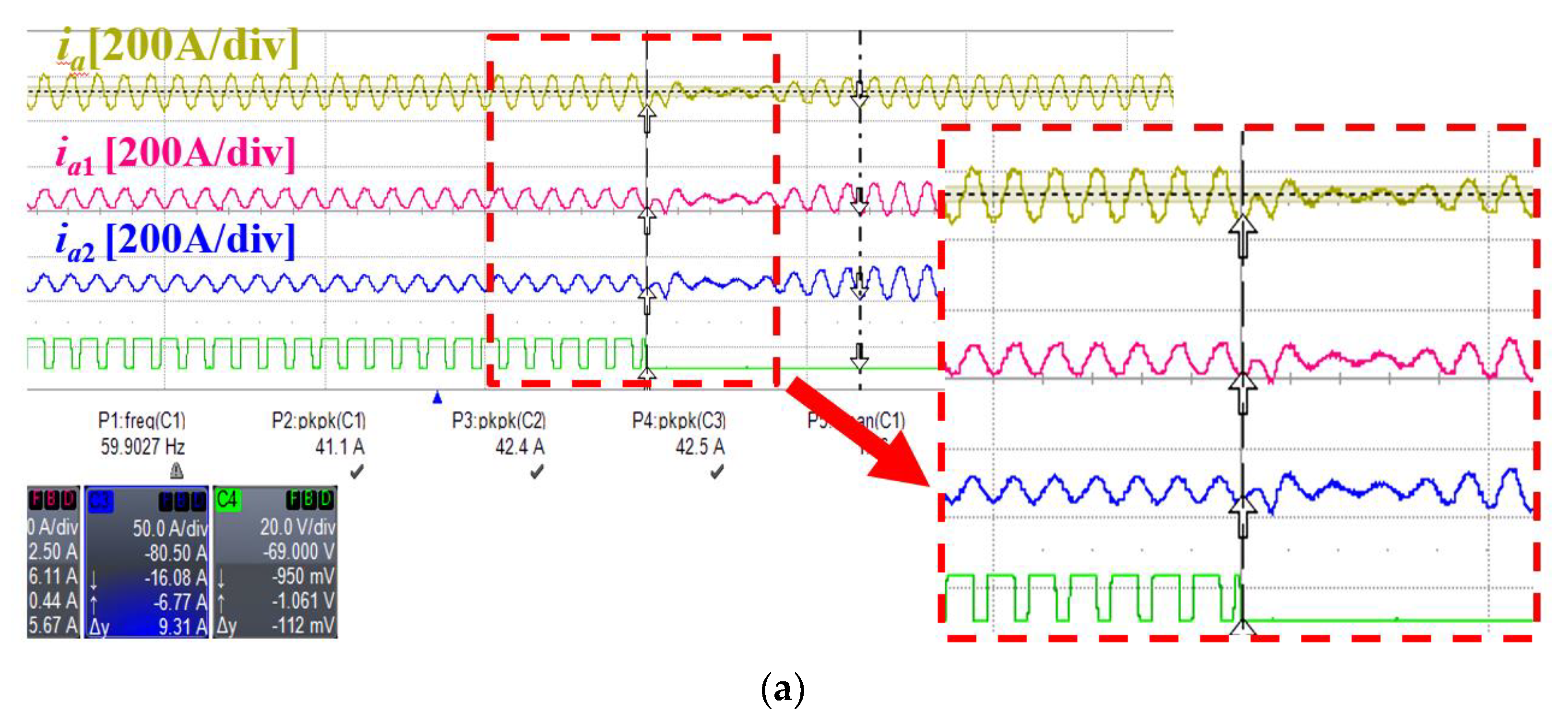
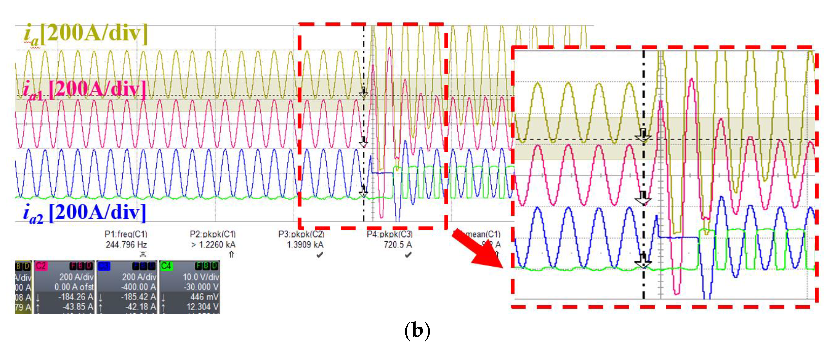
Figure 14 shows the speed-changing current waveform process analyzed using a test. As shown in the current waveform, an imbalance occurs in the current waveform instantaneously when a change in speed is performed. A method to solve the imbalance problem is to provide a dead time during the process of changing speeds.
6. Comparison of Electromagnetic Changing Speed Systems
There are various electromagnetic changing speed methods for high-speed and high-torque motors:
Wye-delta method: Operating with wye connections in low-speed areas and operating with delta connections in high-speed regions;
Change in the number of serial turns: In the low-speed region, driving using all the series turns, and in the high-speed region, driving using half of the total number of series turns.
Change in the number of parallel paths: A method of operating with a low number of parallel paths in the low-speed region and changing the number of parallel paths in the high-speed region to a number that is higher than the number of parallel paths in the low-speed region.
The three speed-changing methods achieve high torques at low speeds, and the speed range also increased [
19,
20,
21,
22,
23]. In all three methods, stator winding resistances were improved after changing the speeds by changing the stator winding structure to change the speed [
24,
25,
26,
27]. Copper loss accounts for the largest proportion of motor losses, and an improvement of resistance improves the efficiency characteristics and broadens the high efficiency area. The last method comprises the electromagnetic multi-step method introduced above, and the operating characteristics and efficiency characteristics of the case of applying the wye-delta method and the case of applying the method of changing the number of series turns are compared.
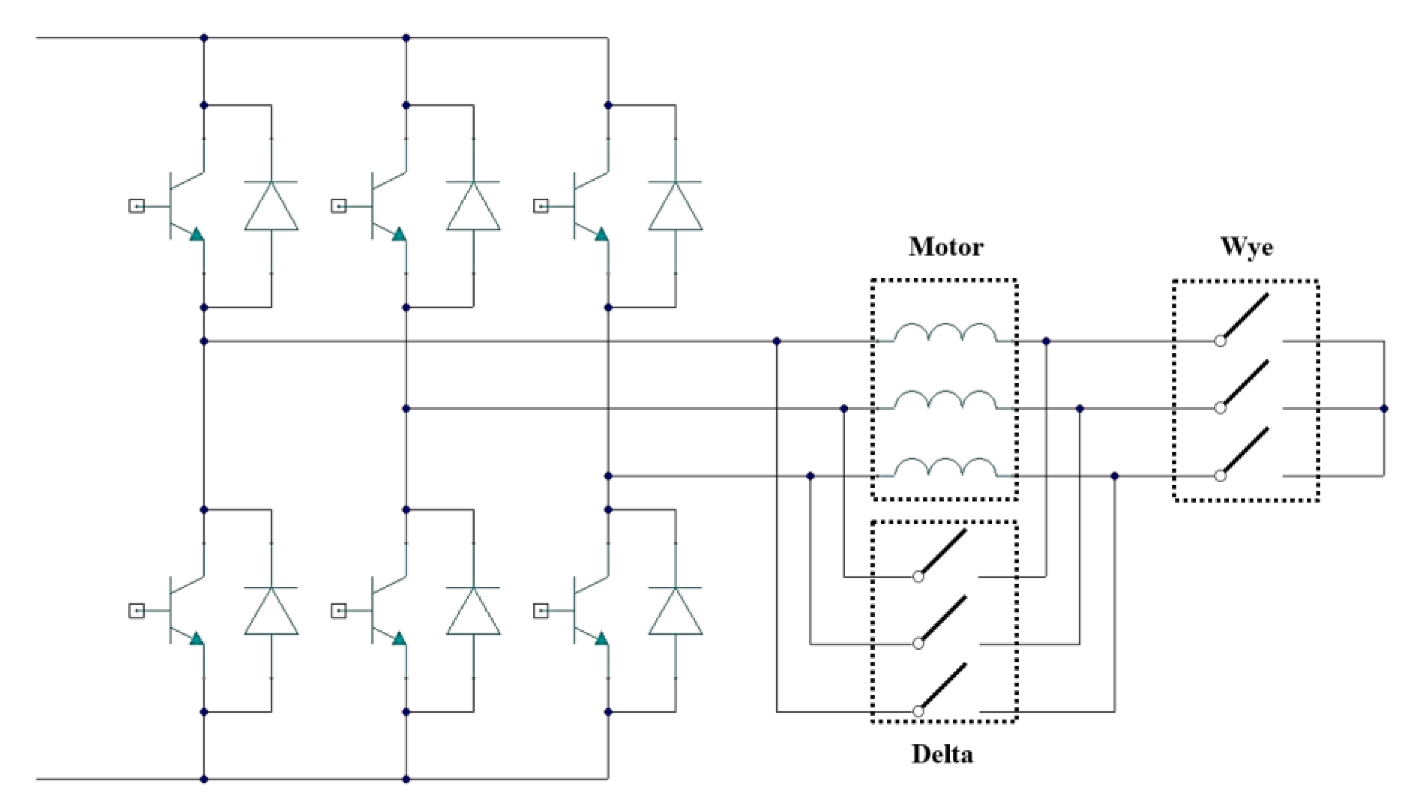
Figure 15 shows the circuit diagram of the wye-delta method. The circuit consists of two groups of switches on the stator winding side, and these are divided into a switch for the wye connection and a switch for the delta connection. At low speeds, it operates with the wye connection, and during the wye connection, the difference between phase voltages and line voltages is 1.73. In the high-speed range via the switching circuit, the operation changed to the delta connection. The characteristic of the delta connection is that the phase voltage and the line voltage are the same.
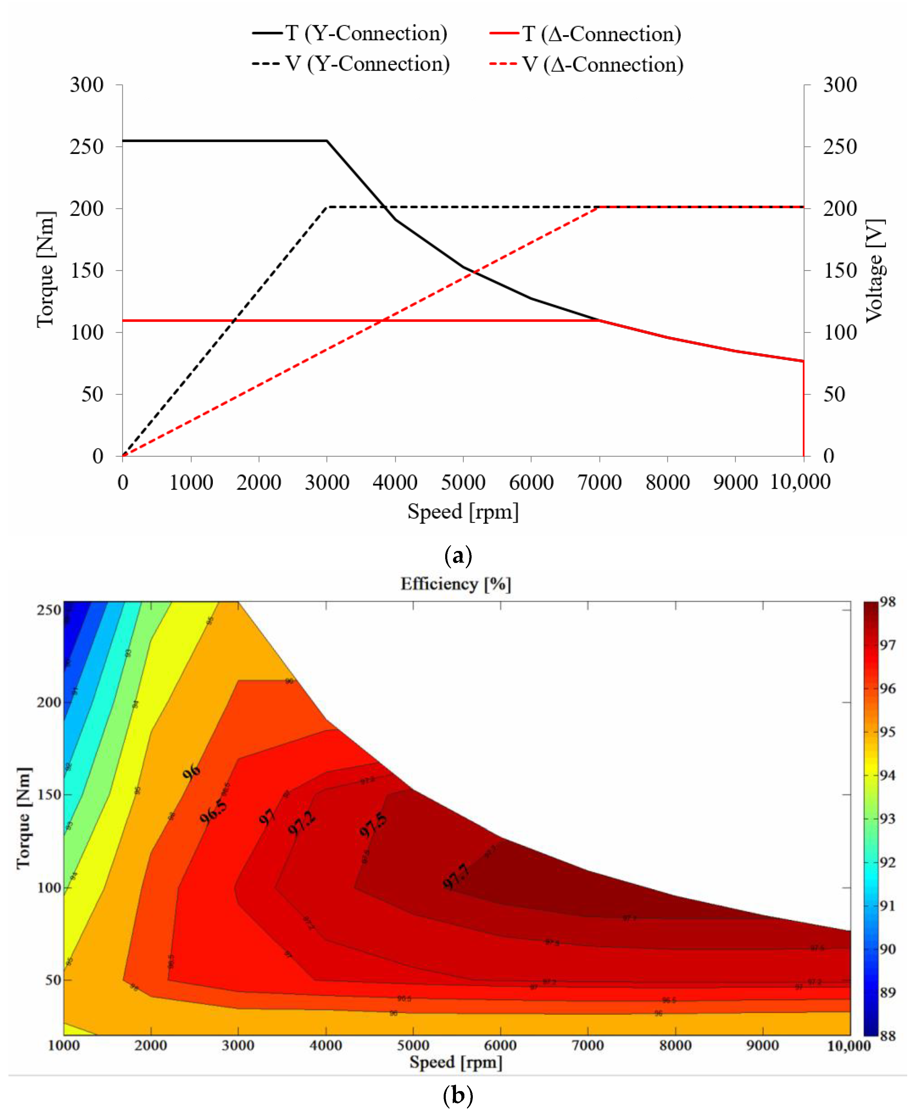
Figure 16 shows the speed, torque characteristic, and voltage characteristic curve of the wye-delta method.
Figure 17 shows a circuit diagram for how to change the number of series turns. The switching box is connected to the total number of series turns and half the number of series turns. At low speeds, it operates using the total number of series turns, and at high speeds, it operates using half the number of series turns.
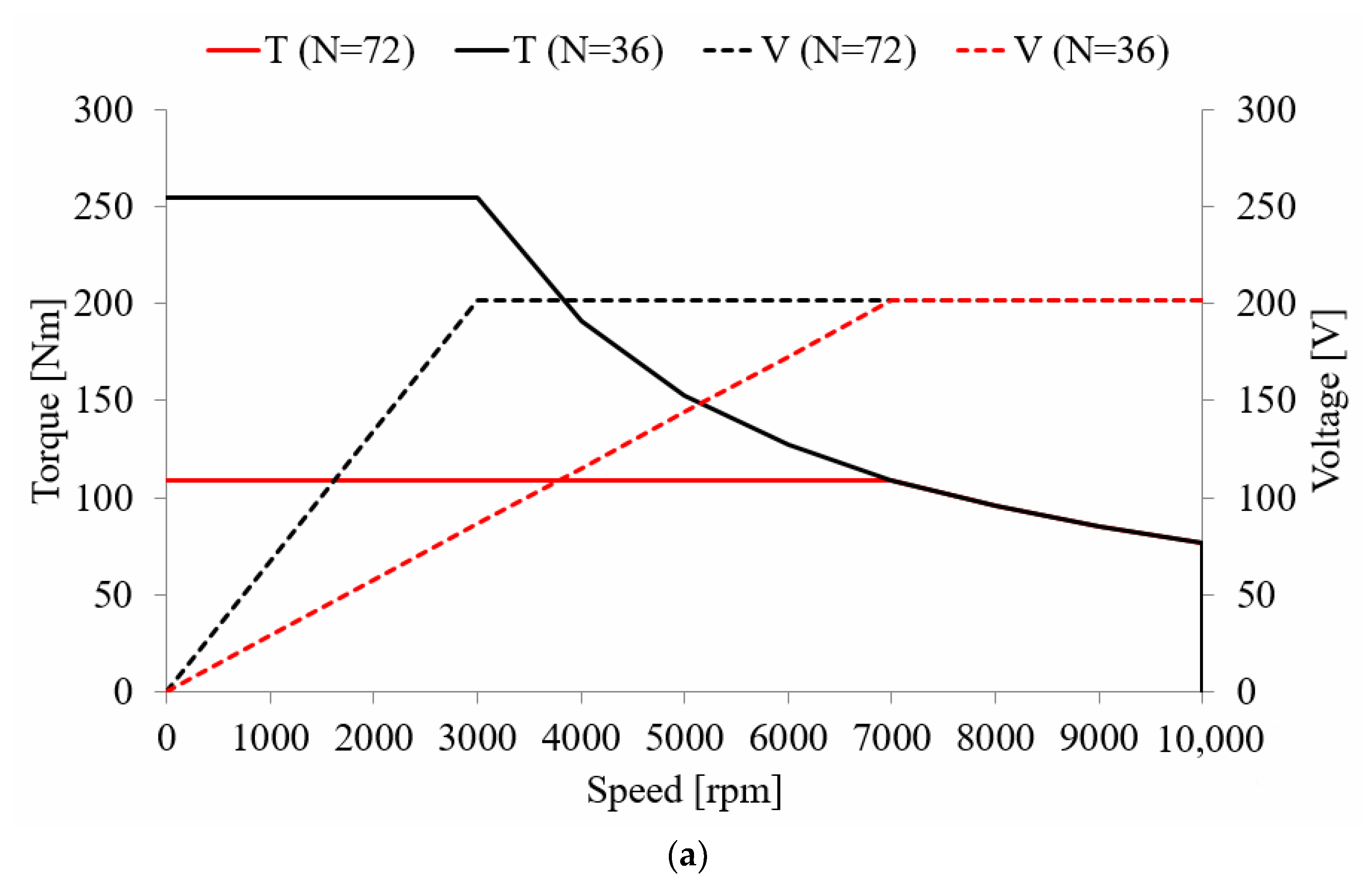
Figure 18 shows the operating characteristic curve and voltage characteristic curve of the method of changing the number of series turns.
Figure 18 shows the efficiency characteristics of the wye-delta method and the method of changing the number of series turns. The high efficiency area of the wye-delta method has a wider high efficiency area compared to the high efficiency area of the series turn change method. However, compared with the efficiency characteristics of the parallel path number change method, the wye-delta method and the series turns method have high efficiency and a wide efficiency area.
7. Conclusions
In this paper, we propose a method for increasing the operating area using electromagnetic multi-step transmissions for a limited operating area due to an increase in back electromotive force with increasing speeds. Using electromagnetic multi-step shifting, the high torque requirement is satisfied at low speeds, and high speeds were achieved. The electromagnetic multi-step shifting technology uses a method of varying the number of parallel paths of the stator by using a switch. A thyristor is used as a shift switch to change the number of parallel paths in the stator. The base speed, voltage, and efficiency characteristics were analyzed by applying the number of parallel paths. Based on the results of the analysis, the base speed in parallel path 4 was selected as the shifting point. The driving range and high-efficiency area are expanded via the application of electromagnetic shifting technology. As the number of parallel paths is changed by shifting, the resistance decreases and copper loss, which accounts for the largest portion of losses, is reduced, thereby increasing the efficiency of the system. In addition, since the voltage saturation point of parallel path 4 exists after the shift, the maximum efficiency point formed within the post-shift region.
By applying the method used in other research cases, the driving characteristics and efficiency characteristics are compared by further analyses. The comparative study is the wye-delta method and the method of changing the number of equivalent series turns. Existing studies satisfied the results of increasing the driving range by focusing on the shift method. On the contrary, the purpose of increasing the operation area and the additional effect is to increase the high efficiency area. The efficiency characteristics of the wye-delta method, the method of changing the number of equivalent series turns, and the method of changing the number of parallel paths were compared. As a result of comparative analysis using simulations, the maximum efficiency range of the method of changing the number of parallel paths is 98.5~90%. When the wye-delta method is applied to the same model, the maximum efficiency area is 97.5~98%, and the maximum efficiency area of the equivalent serial number change method is at the same level as the wye-delta method, but the range is smaller. I think the method proposed in this paper is effective because the research direction of the motor aims at high speeds and high efficiency. However, all three methods change the stator winding via the switch circuit, and current imbalance and transient state appear in the shifting process. This problem appears due to the effect of inductance, and some studies solve the problem by giving a dead time as an existing research case, and the problem can be improved by applying it.
Author Contributions
Conceptualization, C.-H.L.; data curation, C.-H.L. and H.-S.S.; formal analysis, C.-H.L.; investigation, H.-S.S. and H.-R.N.; supervision, K.-C.K.; writing—original draft, C.-H.L.; writing—review and editing, K.-C.K. All authors have read and agreed to the published version of the manuscript.
Funding
This work was supported by the Technology Innovation Program (20011435, Development of large capacity E-transaxle and application technology of 240kW class in integrated rear axle for medium and large commercial vehicles) funded by the Ministry of Trade, Industry and Energy (MOTIE, Korea). This work was supported in part by the Korea Institute of Energy Technology Evaluation and Planning (KETEP) and in part by the Ministry of Trade, Industry and Energy (MOTIE) of the Republic of Korea under Grant 20204030200080.
Data Availability Statement
Not applicable.
Conflicts of Interest
The authors declare no conflict of interest.
References
- Jung, H.-C.; Park, G.-J.; Kim, D.-J.; Jung, S.-Y. Optimal design and validation of IPMSM for maximum efficiency distribution compatible to energy consumption areas of HD-EV. IEEE Tras. Magn. 2017, 53, 1–4. [Google Scholar] [CrossRef]
- Fang, L.; Jung, J.; Hong, J.; Lee, J. Study on high-efficiency performance in interior permanent-magnet synchronous motor with double-layer PM design. IEEE Tras. Magn. 2008, 44, 4393–4396. [Google Scholar] [CrossRef]
- Ghosh, E.; Mollaeian, A.; Hu, W.; Kar, N.C. A novel control strategy for online harmonic compensation in parametrically unbalanced induction motor. IEEE Tras. Magn. 2016, 52, 1–4. [Google Scholar] [CrossRef]
- Yamazaki, K.; Togashi, Y. Shape optimization procedure of interior permanent magnet motors considering carrier harmonic losses caused by inverters. IEEE Tras. Magn. 2018, 54, 1–4. [Google Scholar] [CrossRef]
- Kim, J.-W.; Kim, B.-T.; Kwon, B.-I. Optimal stator slot design of inverter-fed induction motor in consideration of harmonic losses. IEEE Tras. Magn. 2005, 41, 2012–2015. [Google Scholar]
- Zeng, Z.; Shen, Y.; Lu, Q.; Gerada, D.; Wu, B.; Huang, X.; Gerada, C. Flux-density harmonics analysis of switched-flux permanent magnet machines. IEEE Tras. Magn. 2019, 55, 1–7. [Google Scholar] [CrossRef]
- Osama, M.; Lipo, T.A. A new inverter control scheme for induction motor drives requiring wide speed range. IEEE Trans. Ind. Appl. 1996, 32, 938–944. [Google Scholar] [CrossRef]
- Yuzawa, N.; Sakai, K. A permanent magnet motor capable of pole changing for variable speed drive. In Proceedings of the 2013 International Conference on Electrical Machines and Systems (ICEMS), Busan, Korea, 26–29 October 2013; pp. 1127–1132. [Google Scholar]
- Sakai, K.; Yuzawa, N. Permanent magnet motor capable of pole changing for high efficiency. In Proceedings of the 2013 IEEE Energy Conversion Congress and Exposition, Denver, CO, USA, 15–19 September 2013; pp. 5064–5071. [Google Scholar]
- Kazuto, S.; Yuzawa, N.; Hashimoto, H. Permanent magnet motors capable of pole changing and three-torque-production mode using magnetization. IEEJ J. Ind. Appl. 2013, 2, 269–275. [Google Scholar]
- Sakai, K.; Yuzawa, N. Realizing high efficiency using pole-changing hybrid permanent magnet motors. In Proceedings of the 2013 International Electric Machines & Drives Conference, Chicago, IL, USA, 12–15 May 2013; pp. 462–467. [Google Scholar]
- Miller, J.M.; Stefanovic, V.; Ostovic, V.; Kelly, J. Design considerations for an automotive integrated starter-generator with pole-phase modulation. In Conference Record of the 2001 IEEE Industry Applications Conference. 36th IAS Annual Meeting (Cat. No.01CH37248); IEEE: New York, NY, USA, 2001; Volume 4, pp. 2366–2373. [Google Scholar]
- Sakai, K.; Yuzawa, N. Effects of pole changing in a permanent magnet motor. In Proceedings of the 2013 15th European Conference on Power Electronics and Applications (EPE), Lille, France, 2–6 September 2013; pp. 1–8. [Google Scholar]
- Kume, T.; Swamy, M. A quick transition electronic winding changeover technique for extended speed ranges. In Proceedings of the 2004 IEEE 35th Annual Power Electronics Specialists Conference, Aachen, Germany, 20–25 June 2004; Volume 5, pp. 3384–3389. [Google Scholar]
- Kume, T.; Iwakane, T.; Sawa, T.; Yoshida, T.; Nagai, I. A wide constant power range vector-controlled AC motor drive using winding changeover technique. IEEE Trans. Ind. Appl. 1991, 27, 934–939. [Google Scholar] [CrossRef]
- Takatsuka, Y.; Hara, H.; Yamada, K.; Maemura, A.; Kume, T. A wide speed range high efficiency EV drive system using winding changeover technique and SiC devices. In Proceedings of the 2014 International Power Electronics Conference (IPEC-Hiroshima 2014—ECCE ASIA), Hiroshima, Japan, 18–21 May 2014; pp. 1898–1903. [Google Scholar]
- Chen, C.-H.; Cheng, M.-I.; Tsai, M.-I. Study on a wide speed range integrated electrical transmission system. In Proceedings of the 2005 International Conference on Power Electronics and Drives Systems, Kuala Lumpur, Malaysia, 28 November–1 December 2005; pp. 781–786. [Google Scholar]
- Wang, M.-S.; Hsu, N.-C.; Chiang, C.-Y.; Wang, S.-H.; Shau, T.-C. A novel changeover technique for variable-winding brushless DC motor drives. In Proceedings of the SICE Annual Conference 2010, Taipei, Taiwan, 18–21 August 2010; pp. 2650–2653. [Google Scholar]
- Huang, H.; Chang, L. Electrical two-speed propulsion by motor winding switching and its control strategies for electric vehicles. IEEE Trans. Veh. Technol. 1999, 48, 607–618. [Google Scholar] [CrossRef]
- Swamy, M.M.; Kume, T.; Maemura, A.; Morimoto, S. Extended high-speed operation via electronic winding-change method for AC motors. IEEE Trans. Ind. Appl. 2006, 42, 742–752. [Google Scholar] [CrossRef]
- Misir, O.; Raziee, S.M.; Hammouche, N.; Klaus, C.; Kluge, R.; Ponick, B. Calculation method of three-phase induction machines equipped with combined star-delta windings. In Proceedings of the 2016 XXII International Conference on Electrical Machines (ICEM), Lausanne, Switzerland, 1–4 September 2016; pp. 166–172. [Google Scholar]
- Cistelecan, M.V.; Ferreira, F.J.T.E.; Popescu, M. Adjustable Flux three-phase ac machines with combined multiple-step star-delta winding connections. IEEE Trans. Energy Convers. 2010, 25, 348–355. [Google Scholar] [CrossRef]
- Ni, R.; Gui, X.; Wang, G.; Zhang, G.; Xu, D. Improvements in permanent magnet synchronous machines with delta-connected winding. In Proceedings of the IECON 2014—40th Annual Conference of the IEEE Industrial Electronics Society, Dallas, TX, USA, 29 October–1 November 2014; pp. 3837–3842. [Google Scholar]
- Raziee, S.M.; Misir, O.; Ponick, B. Combined star-delta winding analysis. IEEE Trans. Energy Convers. 2018, 33, 383–394. [Google Scholar] [CrossRef]
- Chidambaram, P.; Subbiah, M.; Krishnamurthy, M.R. Generalized theory for the performance of three-phase induction motor with star-delta winding. Electr. Mach. Power Syst. 1987, 12, 383–396. [Google Scholar] [CrossRef]
- Rawcliffe, G.H.; Burbidge, R.F.; Fong, W. Induction-motor speed-changing by pole-amplitude modulation. Proc. Inst. Elect. Eng. 1958, 105, 411–419. [Google Scholar] [CrossRef]
- Ostovic, V. Pole-changing permanent-magnet machines. IEEE Trans. Ind. Appl. 2002, 38, 1493–1499. [Google Scholar] [CrossRef]
Figure 1.
Vector diagram of IPMSM.
Figure 1.
Vector diagram of IPMSM.
Figure 2.
Design of an 80 kW IPMSM model for FEM analysis.
Figure 2.
Design of an 80 kW IPMSM model for FEM analysis.
Figure 3.
Analysis of back electromotive force for selecting the base speed of the parallel path 4 model.
Figure 3.
Analysis of back electromotive force for selecting the base speed of the parallel path 4 model.
Figure 4.
Characteristics of torque and voltage according to speed by the model. (a) Parallel path 2 model. (b) Parallel path 4 model.
Figure 4.
Characteristics of torque and voltage according to speed by the model. (a) Parallel path 2 model. (b) Parallel path 4 model.
Figure 5.
Characteristics of efficiency by model. (a) parallel paths 2 model. (b) parallel paths 4 model.
Figure 5.
Characteristics of efficiency by model. (a) parallel paths 2 model. (b) parallel paths 4 model.
Figure 6.
Winding diagram before and after change speed. (a) Parallel path 2 model. (b) Parallel path 4 model.
Figure 6.
Winding diagram before and after change speed. (a) Parallel path 2 model. (b) Parallel path 4 model.
Figure 7.
Winding diagram of the stator of IPMSM.
Figure 7.
Winding diagram of the stator of IPMSM.
Figure 8.
Circuit of electromagnetic multi-step transmission. (a) Parallel path 2. (b) Parallel path 4.
Figure 8.
Circuit of electromagnetic multi-step transmission. (a) Parallel path 2. (b) Parallel path 4.
Figure 9.
Effect of applying electromagnetic multi-step transmissions. (a) Operating characteristics. (b) Efficiency characteristics.
Figure 9.
Effect of applying electromagnetic multi-step transmissions. (a) Operating characteristics. (b) Efficiency characteristics.
Figure 10.
FEM analysis of current waveforms in the switching process. (a) Step 1 to step 2. (b) Step 2 to step.
Figure 10.
FEM analysis of current waveforms in the switching process. (a) Step 1 to step 2. (b) Step 2 to step.
Figure 11.
Slot leakage inductance-related parameters.
Figure 11.
Slot leakage inductance-related parameters.
Figure 12.
Torque waveform during changing speed. (a) Step 1 to step 2. (b) Step 2 to step 1.
Figure 12.
Torque waveform during changing speed. (a) Step 1 to step 2. (b) Step 2 to step 1.
Figure 13.
Photograph of the motor-switching experiment configuration.
Figure 13.
Photograph of the motor-switching experiment configuration.
Figure 14.
Experimental current waveform. (a) Step 1 to step 2. (b) Step 2 to step 1.
Figure 14.
Experimental current waveform. (a) Step 1 to step 2. (b) Step 2 to step 1.
Figure 15.
Wye-delta transmission circuit diagram.
Figure 15.
Wye-delta transmission circuit diagram.
Figure 16.
Characteristics of wye-delta transmissions. (a) Operating characteristics. (b) Efficiency characteristics.
Figure 16.
Characteristics of wye-delta transmissions. (a) Operating characteristics. (b) Efficiency characteristics.
Figure 17.
Change in the number of series turns transmission: circuit diagram.
Figure 17.
Change in the number of series turns transmission: circuit diagram.
Figure 18.
Characteristics of change the number of series turns transmission. (a) Operating characteristics. (b) Efficiency characteristics.
Figure 18.
Characteristics of change the number of series turns transmission. (a) Operating characteristics. (b) Efficiency characteristics.
Table 1.
Specifications of the 80 kW IPMSM.
Table 1.
Specifications of the 80 kW IPMSM.
| Parameter | Base Model | Unit |
|---|
| Number of poles/slots | 8/48 | - |
| Max torque | 254.65 | Nm |
| Operation range(Base/Max) | 3000/8000 | rpm |
| Power | 80 | kW |
| Stator outer diameter | 200 | mm |
| Rotor outer diameter | 130 | mm |
| Stack length | 140 | mm |
| Parallel paths | 2 | - |
| Number of turns | 9 | - |
| Publisher’s Note: MDPI stays neutral with regard to jurisdictional claims in published maps and institutional affiliations. |
© 2022 by the authors. Licensee MDPI, Basel, Switzerland. This article is an open access article distributed under the terms and conditions of the Creative Commons Attribution (CC BY) license (https://creativecommons.org/licenses/by/4.0/).


