Article

Optimal Ultra-Local Model Control Integrated with Load Frequency Control of Renewable Energy Sources Based Microgrids

1
Department of Electrical Engineering, Faculty of Engineering, Aswan University, Aswan 81542, Egypt
2
Department of Electrical Engineering, Faculty of Energy Engineering, Aswan University, Aswan 81528, Egypt
3
Department of Electrical Engineering, University of Jaén, 23700 Linares, Spain
4
Department of Electrical Power Engineering and Mechatronics, Tallinn University of Technology, 19086 Tallinn, Estonia
5
Electrical Engineering Department, Faculty of Engineering, South Valley University, Qena 83521, Egypt
*
Authors to whom correspondence should be addressed.
Energies 2022, 15(23), 9177; https://doi.org/10.3390/en15239177
Submission received: 5 November 2022 / Revised: 25 November 2022 / Accepted: 29 November 2022 / Published: 3 December 2022
(This article belongs to the Special Issue Analysis of Electricity Distribution Network and Electricity Markets)

Abstract

:
Since renewable energy sources (RESs) have an intermittent nature, conventional secondary frequency control, i.e., load frequency control (LFC), cannot mitigate the effects of variations in system frequency. Thus, this paper proposes incorporating ultralocal model (ULM) control into LFC to enhance microgrid (µG) frequency stability. ULM controllers are regarded as model-free controllers that yield high rejection rates for disturbances caused by load/RES uncertainties. Typically, ULM parameters are set using trial-and-error methods, which makes it difficult to determine the optimal values that will provide the best system performance and stability. To address this issue, the African vultures optimization algorithm (AVOA) was applied to fine-tune the ULM parameters, thereby stabilizing the system frequency despite different disturbances. The proposed LFC controller was compared with the traditional secondary controller based on an integral controller to prove its superior performance. For several contingencies, the simulation results demonstrated that the proposed controller based on the optimal ULM coupled with LFC could significantly promote RESs into the µG.

1. Introduction

Nowadays and in the future, electrical power represents an essential pillar of life. Renewable energy sources (RESs) are considered a haven for dealing with the risks of the high prices of traditional sources, the threat of climate change, and the continuous growth of load demands [1,2]. In rural or remote areas, RESs could offer clean electricity at an affordable price that could eventually drop to grid parity [3]. However, on the other hand, integrating more RES-operated plants into traditional power systems (PSs) creates challenges for the operators of these networks, particularly since the intermittent nature of these resources creates fluctuations in the generated power, making these resources non-dispatchable. This causes voltage and frequency fluctuations and the lack of reactive power, but the most difficult challenge is represented in the lack of inertia due to the use of connecting converters, which worsens the stability of the systems and increases frequency deviations. All these challenges, in addition to issues already existing in networks, such as voltage fluctuations and the frequency deviations that result from the imbalance between generation and load demand, lead to further threats to the stability and security of these networks. This prompts the idea of replacing traditional PSs that have to integrate with more plants operating with RESs with micro-grids (µGs) as an attractive solution to these challenges. This caused the current trend to divide traditional PSs into a group of µGs [4,5,6,7]. Because a µG is viewed as a controllable entity able to be operated at either grid-linked or isolated modes, they typically consist of a separate collection of small-scale distributed RES-based generation units with energy storage systems (ESSs) and local loads [8].
Under actual operational circumstances, continuous variations are always occurring in the variables of system models; these variations are increased and occur more rapidly in µGs with diverse resources due to the utilization of different RESs with unpredictable natures. As an detrimental result, a mismatch of frequencies in the µGs arises, which is considered the primary source of instability and system breakdown. Typical regulators used in µGs for frequency dampening cannot provide system stability [9]. µGs, like any PS, must fulfill specific mandated dependability and adequacy requirements, which require all controlled components to actively participate in keeping the voltage and frequency of the grid within safe operating limits. Indeed, the lack of inertia, abrupt variations in RES-produced power, and the imbalance between generation and demand during load/source fluctuations make it difficult to keep the frequency within its desired limits, especially when the µG is used in a standalone condition [10,11].
As a result, load frequency control (LFC) is crucial in µGs to keep the system frequency at their predetermined levels. In this regard, numerous control techniques/strategies have been proposed for the frequency regulation of power systems considering RESs. A developed model of a photovoltaic (PV) system has been proposed for LFC studies in [3]. Fractional-order control theory has been applied to design an LFC based on the RUNge Kutta optimizer to enhance the frequency stability of a multisource power system considering RESs and electric vehicles [5]. Moreover, an adaptive fractional order PID controller based on a genetic algorithm has been designed to enhance the dynamic performance of a PV/wind-connected grid [12]. A novel LFC technique based on an optimal reset control has been proposed for the frequency regulation of an islanded µG [7]. The contribution of electric vehicles in enhancing the frequency stability of µGs was addressed in [8]. Additionally, an adaptive model predictive control has been presented to enhance the frequency stability of an islanded µG considering electric vehicles and ESSs [9]. Based on the literature survey of LFC studies conducted, the LFC control technologies used can be categorized as conventional controllers and their modifications [5,8,13], fuzzy logic controllers [6,14,15], various robust controllers [11,16,17,18], model predictive controllers [9,19,20], and others. Even while the previously stated control schemes have provided the examined PSs with a superior dynamic response, they might not be able to survive severe disruptions that result from a high share of RESs. Additionally, these controllers require accurate modeling of the considered µG, which is considered a significant challenge. Moreover, although the aforementioned robust control schemes have demonstrated outstanding performance in terms of µG stabilization, these techniques need proper modeling for µGs. However, as the disturbances and scale of RESs in µGs grow, so does the complexity of the robust control schemes that govern such systems.
Based on the above motivations, the use of intelligent controllers (e.g., ultralocal model (ULM)-based controllers) in the LFC of power systems has become very necessary to deal with load/RES uncertainty issues in today’s power systems. ‘Model-independent adjustments’ or ‘intelligent controllers’ are terms used to describe data-driven model-independent systems. Intelligent PID (iPID) controller-based ULM controllers are among the most prevalent model-independent systems based on input–output data. In this technique, the uncertainties and unknown model parameters have to be estimated, which is frequently accomplished by algebraic schemes or time-delay estimation. However, the estimate of these observers is sluggish, and they are unable to swiftly reduce the tracking error. One approach to this problem is to use an extended state observer to estimate the unknown sections. However, due to the effect of the uncertainties, the use of an extended state observer may lead to the appearance of a nonzero error. As a result, different supplemental approaches like fuzzy logic and neural networks have been used to avoid observer error [6].
To meet the existing and future requirements and challenges of grids, this study is focused on delivering a µG that has a high degree of RESs penetration. Furthermore, this paper proposes to improve the frequency stability of a µG by incorporating a ULM controller into the existing secondary frequency control loop (i.e., integral controller). The basic secondary frequency controller in the µG was built on the integral controller. Therefore, the whole controller structure could be called an ‘intelligent integral controller.’ The output of the proposed secondary controller represents the power command into the turbine’s governor of the conventional power plant. In addition, the design of the ULM receives the previous control input signal beside the frequency deviation of the µG. To improve the performance of the ULM with LFC, its parameters were designed optimally by applying the African Vultures Optimization Approach (AVOA). The performance of the proposed intelligent-controller-based LFC was evaluated and compared with the conventional integral secondary controller under different contingencies in the µG.
The rest of this paper is organized as follows: The studied µG configuration is provided in Section 2. Section 3 introduces the proposed ultralocal model control to integrate with the second frequency controller of the µG, and the applied optimization algorithm based on the AVOA is also introduced. The simulation results based on the MATLAB/Simulink software are given in Section 4. Finally, the conclusion of the paper is reported in Section 5.

2. Configuration and Modeling of the Studied Islanded µG

2.1. Structural Details of the Islanded µG

Generally, the main structure of a µG includes two other main elements, such as distributed generators (DGs) that look like micro sources in the µG configuration and local loads (i.e., residential and nonresidential loads). DGs typically come in two varieties: nondispatchable DGs that use RESs (such as solar, biomass, wind, and geothermal energy) with unpredictable outputs and dispatchable DGs that use controllable input generators (such as tiny thermal power plants) [21]. This study sheds light on operation of an islanded µG with hybrid power plants (PPs), including 20 MW thermal PP, 4 MW solar PP, 8 MW wind PP, and 15 MW load demands. The power base of the system equals 20 MW. Figure 1 displays a simplified representation of the studied islanded µG.
To provide a realistic perception of the studied µG, this work considers the significant, inherent nonlinear needs and the physical restrictions imposed by the dynamics of the system of the generating units. One of the essential limits on the PPs considered in this study is the variation rate of the produced power due to the relative limitation of mechanical motions. The physical system of the studied PP’s dynamics can be described as the following:
  • The valve gate’s limits (upper limit ‘VU’ and lower limit ‘VL’) regulate the valve’s opening and shutting.
  • The generation rate constraints (GRCs) are used to restrict the rate of the produced power. The non-reheat thermal PP’s GRC is set at 20% pu. MW/minute [22].
Figure 2 depicts a dynamic model of the studied µG with the proposed LFC strategy, while Table 1 lists the dynamic parameters of the investigated µG considering RESs.

2.2. Dynamic Modeling in the State-Space

A state-space model (SSM) is an efficient approach for ensuring the robustness of the control design in the suggested µG control strategy [23]. The considered SSM is a fifth-order linearized grid, taking into account a high share of RESs [21]. This work employs two basic control procedures, the primary governor action and the secondary LFC, to address concerns with frequency stability caused by RESs in the µG. The derivative of the frequency deviation (Δf) of the µG can be formulated as
Δ f ˙ = 1 2 H ( Δ P m + Δ P W T + Δ P P V Δ P L ) D 2 H Δ f    
where
Δ P g ˙ = 1 T g ( Δ P g ) 1 R . T g Δ f + 1 T g ( Δ P C )
Δ P m ˙ = 1 T t ( Δ P m ) + 1 T t ( Δ P g )
Δ P W T ˙ = 1 T W T ( Δ P W i n d ) 1 T W T ( Δ P W T )
Δ P P V ˙ = 1 T P V ( Δ P S o l a r ) 1 T P V ( Δ P P V )
The power variations in the wind ( Δ P W i n d ), solar ( Δ P S o l a r ) , and load ( Δ P L ) are taken into consideration as disturbance signals in this study. The linearized SSM of the studied islanded µG could be simply created using the appropriate definitions and state variables from Equations (1) to (5) as follows:
X ˙ = A X + B U + E W
Y = C X + D U + Z W
where
X T = [ Δ f Δ P g Δ P m           Δ P W T Δ P P V   ]
W T = [ Δ P W i n d Δ P S o l a r Δ P L ]
Y = [ Δ f ]
where
X: state vector,
B, U: control input signals,
W: input disturbance vector,
E: disturbance inputs,
Y: control output signal,
C: output measurement used as input to the load frequency controller,
D: zero vector with the same size as the input control signal,
Z: zero vector with the same size as the input disturbance vector,
f: deviation of the system frequency.
Then, the complete equations to represent the SSM of the islanded µG taking RESs could be obtained, as given in Equations (6) and (7).
X ˙ = [ D 2 H 0 1 2 H 1 2 H 1 2 H 1 R T g 1 T g 0 0 0 0 1 T t 1 T t 0 0 0 0 0 1 T W T 0 0 0 0 0 1 T P V ] [ Δ f Δ P g Δ P m Δ P W T Δ P P V ] + [ 0 1 T g 0 0 0 ] [ Δ P C ] + [ 0 0 1 0 0 1 2 H 0 0 0 1 T W T 0 0 0 1 T P V 0 ] [ Δ P Wind Δ P Solar Δ P L ]
Y = [ 1 0 0 0 0 ] X

3. Proposed Optimal Ultralocal Model for LFC of µG

3.1. Description of the Ultralocal Model Control

The changes in the input and output of the single-input single-output (SISO) system can be approximately defined using a finite-dimensional ordinary differential equation [24,25].
E ( t , y , y ( 1 ) , , y ( n ) , u , u ( 1 ) , , u ( m ) ) = 0
where E is an unknown nonlinear function, u denotes the control input of the system, y denotes the output variable of the system, and m and n are the control input and output orders of the system, respectively.
The ULM principle can be used to simplify (10) as
y ( n ) = F + α u  
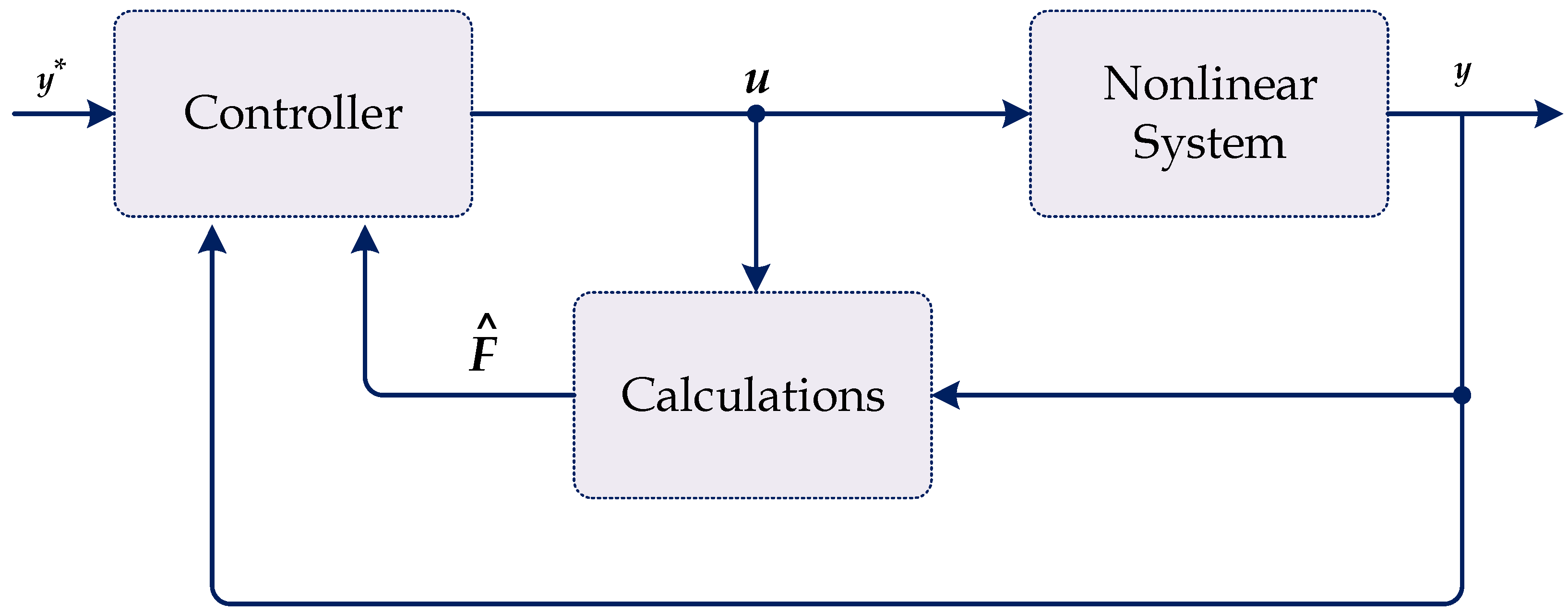
where y ( n ) is the derivative of order n of the system output y, F is the sum of the known and unknown parameters of the system (i.e., it is considered to be the total disturbance and uncertainties of the system in the ULM), and α ∈ R is a nonphysical parameter that finds a balance between the magnitude of y ( n ) and α u . The order n of the output derivative is usually chosen by the practitioner as one or two and one in all actual circumstances (i.e., a first-order system) [26]. In general, the basic structure of the ULM is sketched in Figure 3.
The value of F is constantly updated using the system information of the input and output where it lacks precision and is only an estimate, so Equation (11) can be rewritten as Equation (12) in which F is replaced with F ^ as an indication of the estimation using algebraic identification methods [27]. Then, using operational calculus, the rules yield Equation (12) as Equation (13), in which y 0 denotes the initial value of the output y during the time interval [tL, t].
y ( n ) = F ^ + α u  
s y = F ^ s + α u + y 0 [ M 4 ]  
By multiplying both sides of Equation (13) by d d s and then by s 2 , the value of F ^ in the time domain can be expressed as [28]:
F ^ ( t ) = 3 ! L 3 t L t ( ( L 2 σ ) y ( σ ) + α σ ( L σ ) u ( σ ) ) d σ  
where L has a small value according to the sampling interval and intensity of the noise.
If we consider the sampling time Ts and the window length Nf, then the value of F ^   in Equation (14) can be calculated in the time interval [0, Nf Ts] as in Equation (15). Finally, the value of F ^ can be calculated using Heun’s method based on the input and output information as in Equation (16).
F ^ ( t ) = 3 ! ( N f T s ) 3 0 N f T s ( ( N f T s 2 σ ) y ( σ ) + α σ ( N f T s σ ) u ( σ ) ) d σ  
F ^ = 3 N f 3 T s i = 1 N f ( A + B )
where
A = ( N f 2 ( i 1 ) ) y ( k 1 ) + ( N f 2 i ) y ( k )
B = ( α ( i 1 ) T s ( N f ( i 1 ) ) ) u ( k 1 ) + α i T s ( N f i ) u ( k )
If the system is closed with a proportional controller (that is Kp), then the corresponding control input becomes
u = y ˙ F + K p e α  
where y* is the reference of the system output, while e is the error between the reference and the instantaneous output values (i.e., e = y* − y).

3.2. Proposed Optimal Ultralocal Model Control for LFC

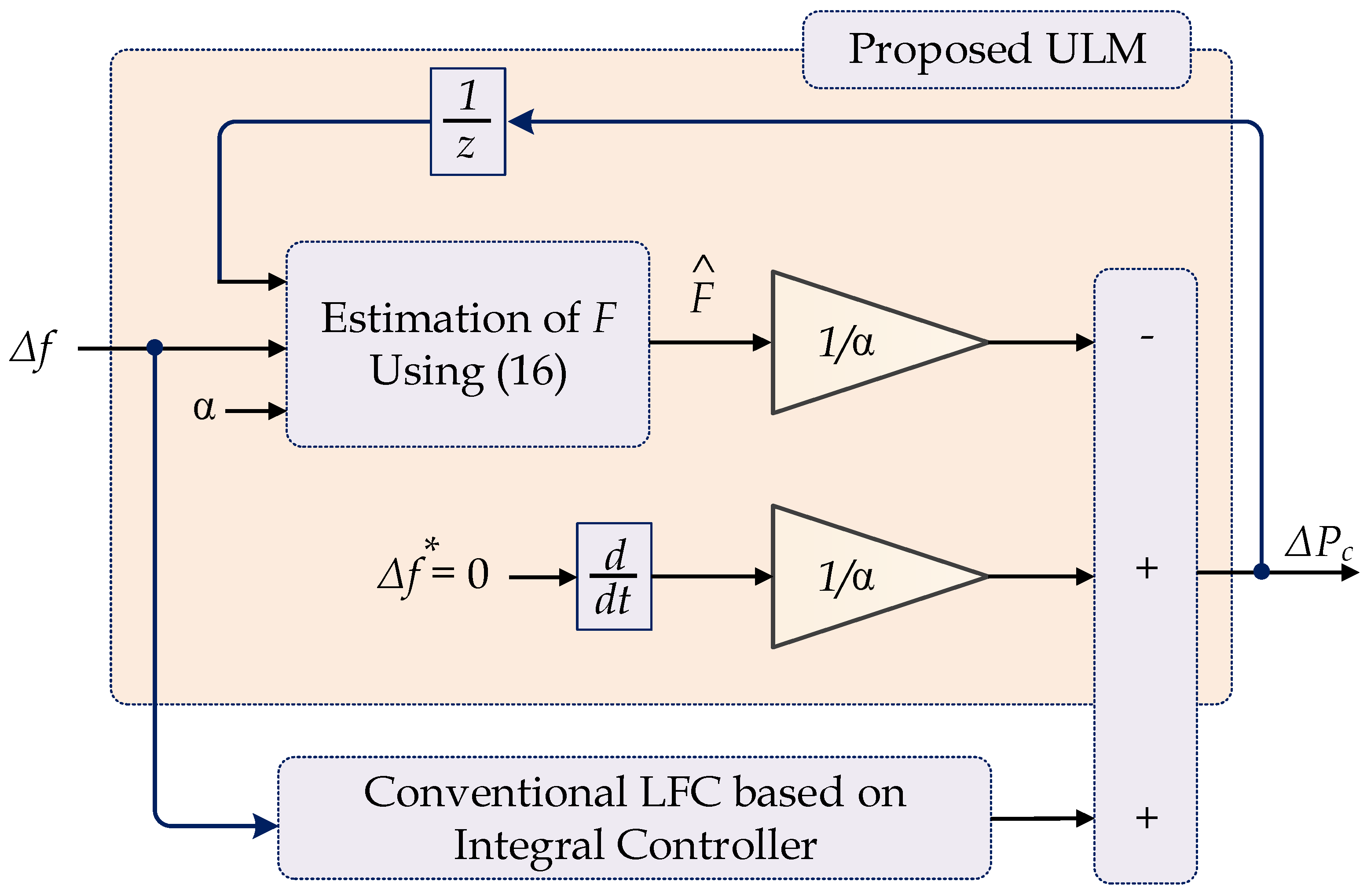
In this study, the basic feedback controller of the secondary loop was designed based on the integral controller; its input is the µG frequency deviation (Δf). The objective of the secondary controller is to maintain the frequency of the system at its nominal value after the disturbance of the system within a time that varies by a few minutes [28]. The ULM part is combined with the secondary integral controller to reduce the frequency deviation, as shown in Figure 4. Therefore, the whole controller structure could be called an ‘intelligent integral,’ where the controller becomes model-free. Using this control strategy eliminates the parameter mismatches that disturb the power system.
When the reference value of the frequency deviation equals zero, the total control input of the proposed controller, which is the incremental power ΔPc, is formulated as
Δ P c = ( F ^ α + K i s ) Δ f  
where s is the Laplace operator, Ki is the integral gain of the secondary controller that is adapted from [28], and F ^ can be computed using (16).
The parameter α   of the ULM can be defined by trial-and-error methodology, which makes the tuning process difficult and depends on the practitioner. Furthermore, these trial-and-error methods make it challenging to obtain the optimal parameter value of α that improves the performance of the system and guarantees the stability of the system against disturbances. Consequently, the system’s robustness is not guaranteed in this case. Therefore, in this paper, a metaheuristic optimization approach based on the AVOA was employed to determine the optimal value of parameter α   of the ULM.

3.3. A metaheuristic Optimization Method Based on the African Vulture Optimization Algorithm:

In this work, to identify the optimal values for the parameters of the suggested control system, the AVOA was used. The AVOA is a brand-new metaheuristic algorithm inspired by nature. Figure 5 outlines the planned AVOA flowchart and steps. The AVOA was established by simulating and modeling the manner of life and foraging of African vultures (AV) based on the following standards:
  • The AV population consists of N Avs, each with a d-dimensional position space.
  • There are three different groups within the AV population. The fitness value of the viable solution determines the quality rank; the best solution is ranked as the leading and first AV, the second-best solution is ranked as the second-best AV, and the remaining Avs are assigned to the third group.
  • The three groups were established in the population to define the most significant natural function of Avs. Therefore, diverse vulture species have unique functions to fulfill.
  • Additionally, the fitness value of a potential solution may indicate both the advantages and disadvantages of Avs. In light of this, the most vulnerable and ravenous vultures tend to be the worst. In contrast, the strongest and most numerous vultures tend to be the best vultures. All Avs in the AVOA often try to stay close to the best ones and stay away from the worst.
To mimic the behavior of several vultures in the foraging stage, the AVOA approach can be divided into five steps according to the four above criteria [29,30].

3.3.1. Step 1: Population Classification

In this step, after the creation of the first population and after determining the suitability of each solution, the best solution is considered the finest and, therefore, the first vulture, while the second solution is regarded as the second-best vulture using Equation (19). The remaining vultures are placed in the third group based on standard No. 2.
R   ( i ) = { B e s t   V u l t u r e 1   i f   p i = L 1   B e s t   V u l t u r e 2   i f   p i = L 2    
p i = F i i = 1 n F i
where;
Best Vulture1: best vulture,
Best Vulture2: second best one,
L1, L2: random variables in the range of [0, 1] where (L1+ L2 = 1),
Fi: fitness of the first and second groups of vultures.
N: total number of the first and second groups of vultures.

3.3.2. Step 2: The Rate of Vulture Starvation

The distances at which vultures search for food depend on their energy unless the vultures are starving. Thus, they can search for food for longer distances when they have high energy. If they are starving, they have less energy, and thus they cannot search for their food for longer distances. The starving vultures will act violently as a result. Therefore, the vulture exploration and exploitation stages can be designed based on this behavior. Equation (21) is used to calculate the ith vulture hunger level “Fi” at the t-th iteration, which is employed as a marker of the vultures’ transition from exploration to exploitation.
F i = (   2 × r a n d i + 1   ) × z × (   1 i t e r a t i o n i m a x i t e r a t i o n s     ) + t
t = h × ( s i n ω   (   π 2 × i t e r a t i o n i m a x i t e r a t i o n s   ) + ( c o s ω   (   π 2 × i t e r a t i o n i m a x i t e r a t i o n s   ) 1 )
where;
Fi: hunger level implies that the vultures ate enough,
randi: variable of a random value ranging from 0 and 1,
z: variable of a random value ranging from −1 and 1, changes with each new iteration,
iterationi: current iteration count,
maxiterations: total iterations count,
h: variable of a random value ranging from −2 and 2,
ω : a parameter with a predetermined value that determines the likelihood the vulture will carry out the exploitation stage,
According to Equation (21), as the count of total iterations increases, Fi decreases significantly. Whenever | F i | > 1 , the vultures begin the exploration stage and look for food in different areas. Otherwise, the vultures enter the exploitation stage and have to search for food in their local surroundings.

3.3.3. Step 3: Stage of Exploration

Vultures have excellent vision, helping them to identify food and dead animals fast. However, vultures may have difficulty obtaining food, as they take much time scanning their location before flying large distances in search of food. In the AVOA, vultures can check numerous random sites using two alternative tactics, and either strategy is selected using a parameter called ‘P1‘ in the range [0, 1].
During the exploration stage, randp1 (random number between 0 and 1) is utilized to select one of the two tactics. If r a n d p 1     P 1 , Equation (23) is used. Otherwise, Equation (24) is used.
P (   i + 1   ) = R (   i   ) D (   i   ) × F i  
P (   i + 1   ) = R (   i   ) F i + r a n d 2 × ( ( u b l b ) ×   r a n d 3 + l b )
D (   i   ) = |   X × R ( i )   P ( i )   |
where;
R (i): one of the finest vultures determined in the current iteration based on Equation (23),
D(i): distance between the vulture and the current optimum vulture,
Fi: the rate of vulture satiation calculated in the current iteration using Equation (25),
rand2: variable of a random number ranging from 0 to 1,
ub: variable upper boundary,
lb: variable lower boundary,
rand3: variable used as a high random coefficient to broaden the search and look for additional search space locations,
P(i): the location of the ith vulture,
X: random variable ranging from 0 and 2.

3.3.4. Step 4: Stage of Exploitation (Phase 1)

The efficiency stage of the AVOA is investigated in this phase. If the magnitude of |Fi| is less than one, the AVOA begins the first phase of exploitation. The parameter P2, which is in the range [0, 1], is used to determine which tactic will be selected. At the beginning of this phase, a random number ranging from 0 and 1 ‘randp2’ is generated. If r a n d p 2     P 2 , then the tactic of siege-fight is implemented slowly. Otherwise, the tactic of rotational flying is implemented. This process is described by Equation (26).
P (   i + 1   ) = {   D ( i ) × (   F i + r a n d 4 ) d ( t )                                       i f   p 2   r a n d p 2     R ( i ) (   S 1 + S 2 )                                                                         i f   p 2 < r a n d p 2    
d ( i ) = R (   i   ) P (   i   )
S 1 = R (   i   ) × (   r a n d 5 × P ( i ) 2 π   ) × cos ( P ( i ) )  
S 2 = R (   i   ) × (   r a n d 6 × P ( i ) 2 π   ) × sin ( P ( i ) )
where;
rand4, rand5, rand6: random numbers ranging from 0 and 1,
d(t): the distance that separates the vulture and one of the two ‘best vultures’ groups.

3.3.5. Step 5: Stage of Exploitation (Phase 2)

This phase is executed only if | F i | < 0.5 . At the beginning of this phase, a random number ranging from 0 and 1 ‘rand3’ is generated. If P 3     r a n d 3 , the approach is to attract a diverse range of vultures to the food source, leading to competitive behavior. As a result, Equation (30) could be used to update the location of the vulture.
P   ( i + 1 ) = A 1 + A 2 2
A 1 = B e s t V u l t u r e 1   ( i ) B e s t V u l t u r e 1   ( i ) × P ( i ) B e s t V u l t u r e 1   ( i ) ( P ( i ) ) 2 × F i
A 2 = B e s t V u l t u r e 1   ( i ) B e s t V u l t u r e 2   ( i ) × P ( i ) B e s t V u l t u r e 2   ( i ) ( P ( i ) ) 2 × F i
Similarly, as the AVOA reaches its second stage, the vultures gather around the best vulture to scavenge the leftover food. As a result, Equation (33) could be used to update the vulture’s location.
P (   i + 1   ) = R (   i   ) | d ( t ) | × F i × L e v y ( d )
In this case, d denotes the issue dimensions. The efficacy of the AVOA was boosted by applying Lévy flight (LF) arrangements drawn from Equation (34).
L F   ( x ) = 0.001 × u × σ   | υ | 1 ρ  
σ = ( Γ   ( 1 + β ) × sin ( π β 2 ) Γ   ( 1 + β 2 ) × β × 2 × ( β 1 2 ) ) 1 ρ  
where;
v, u: random numbers ranging from 0 and 1,
β : constant ( β = 1.5 ) .

4. Simulation Results and Discussion

The efficacy of the proposed intelligent integral controller based on the AVOA was verified through an islanded µG. Moreover, the performance of the proposed load frequency control based on the intelligent integral control was compared with the traditional integral controller under various operating conditions for the studied islanded µG. The natural variations of RESs and the frequent changes in load were all investigated for the considered islanded µG. The examined isolated µG’s simulation results were executed with the MATLAB/Simulink® program to validate the superiority of the proposed controller based on the AVOA. The frequency stabilization of the examined µG, considering the high penetration level of RESs was validated under different operating conditions using the following situations.

4.1. Scenario A: System Performance Appraisal during Abrupt Load Variations

Case 1: Impact of a 5% abrupt load variation on system performance
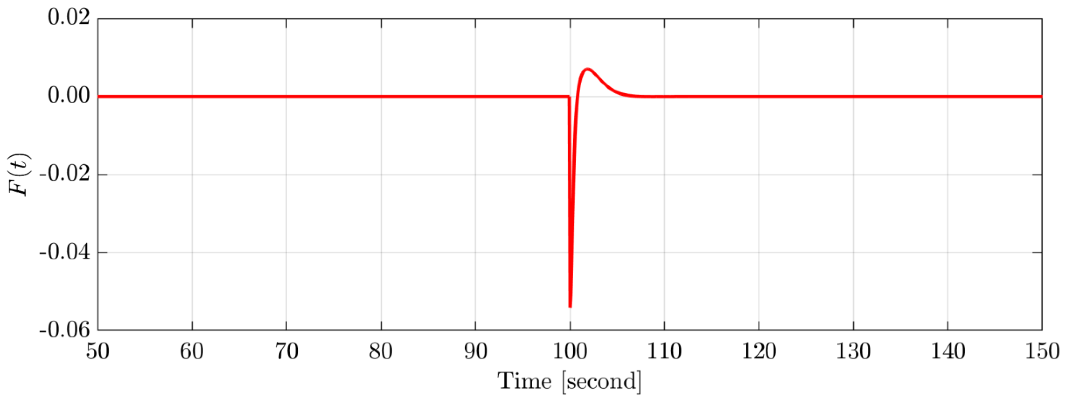
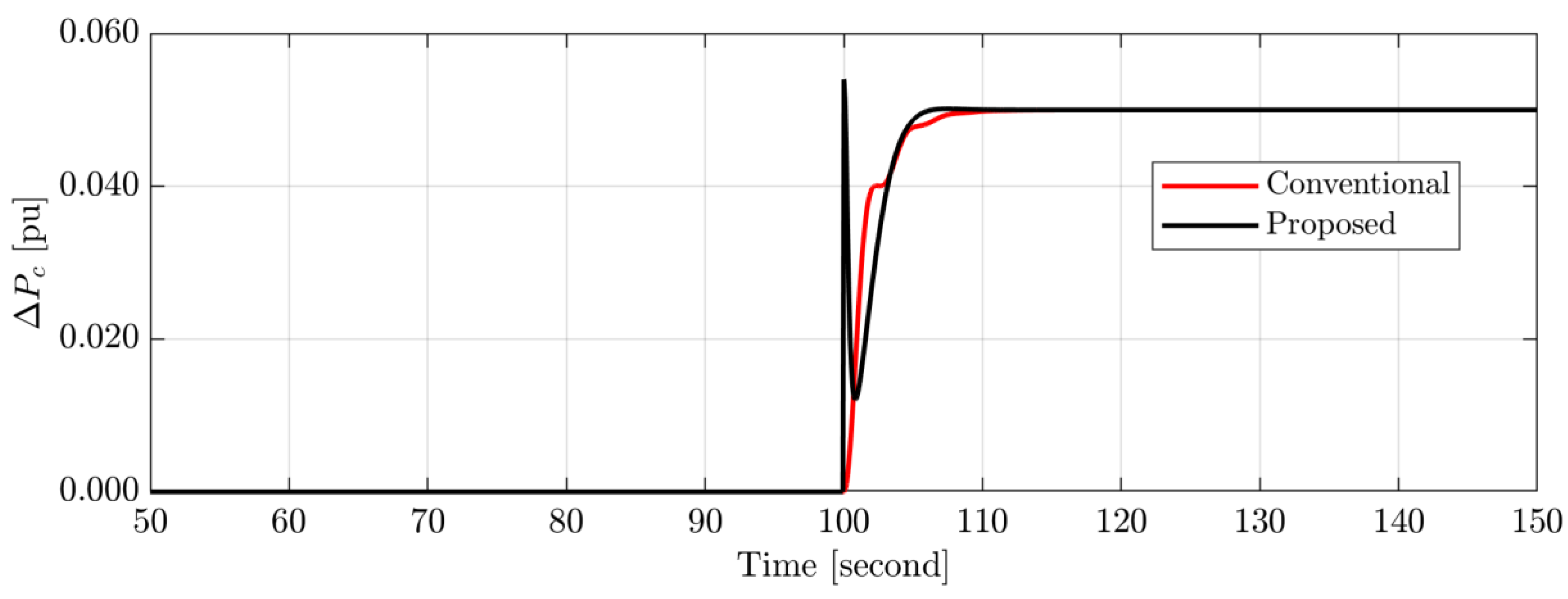
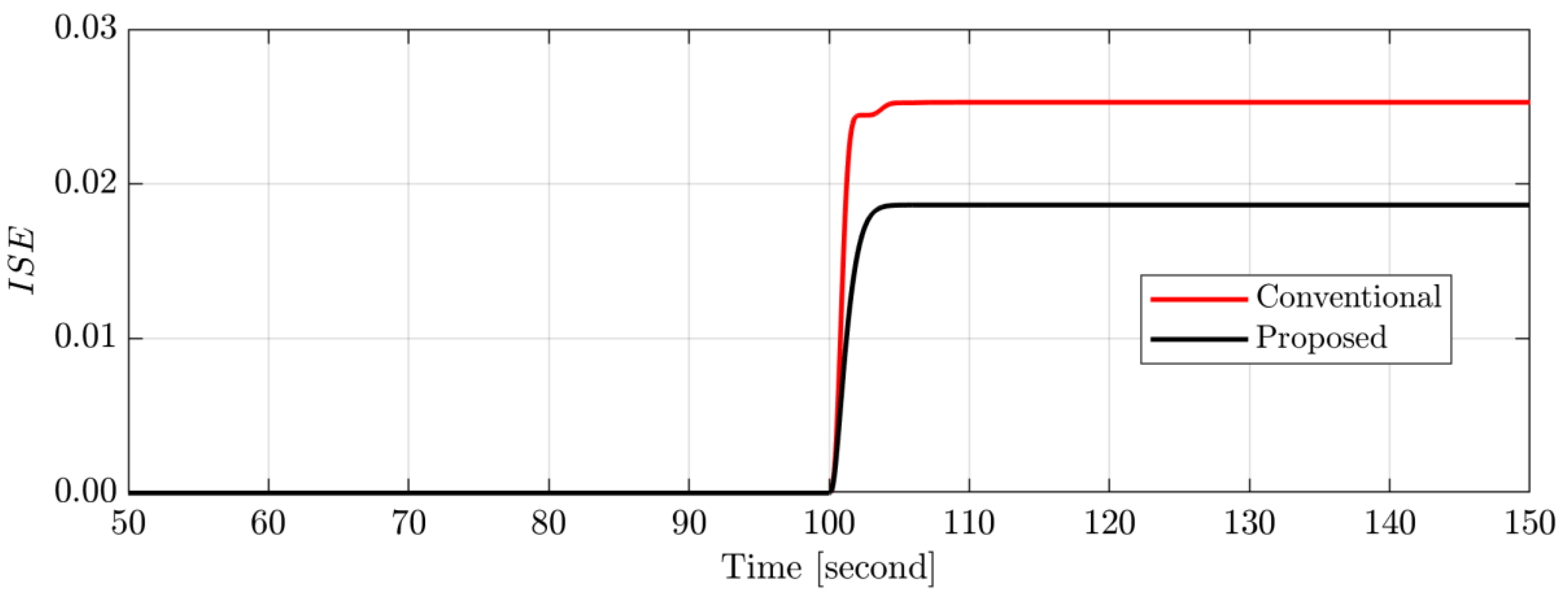
In this case, a + 0.05 p.u. of abrupt load change was applied at the time instant of 100 s to the studied µG with the proposed intelligent integral controller based on the AVOA, as shown in Figure 6. The frequency response of the targeted island µG with the conventional and proposed control techniques is shown in Figure 7. Figure 7 shows that the targeted islanded µG with the proposed intelligent integral controller based on the AVOA is more efficient and dependable than the traditional control system based on the integral controller. The studied µG’s total perturbation and uncertainties in the proposed ULM combined with the secondary frequency control (integral controller) are shown in Figure 8. Moreover, the control output signal of both the conventional integral controller and the proposed intelligent integral controller in the investigated islanded µG are compared in Figure 9. The superiority of the proposed control technique over the conventional control technique has been validated by giving the minimum system objective function (i.e., ISE), as shown in Figure 10. As a result, the proposed LFC technique based on the intelligent integral controller-based AVOA can effectively maintain the frequency stabilization of the considered islanded µG.
Case 2: Impact of a 10% abrupt load variation on system performance
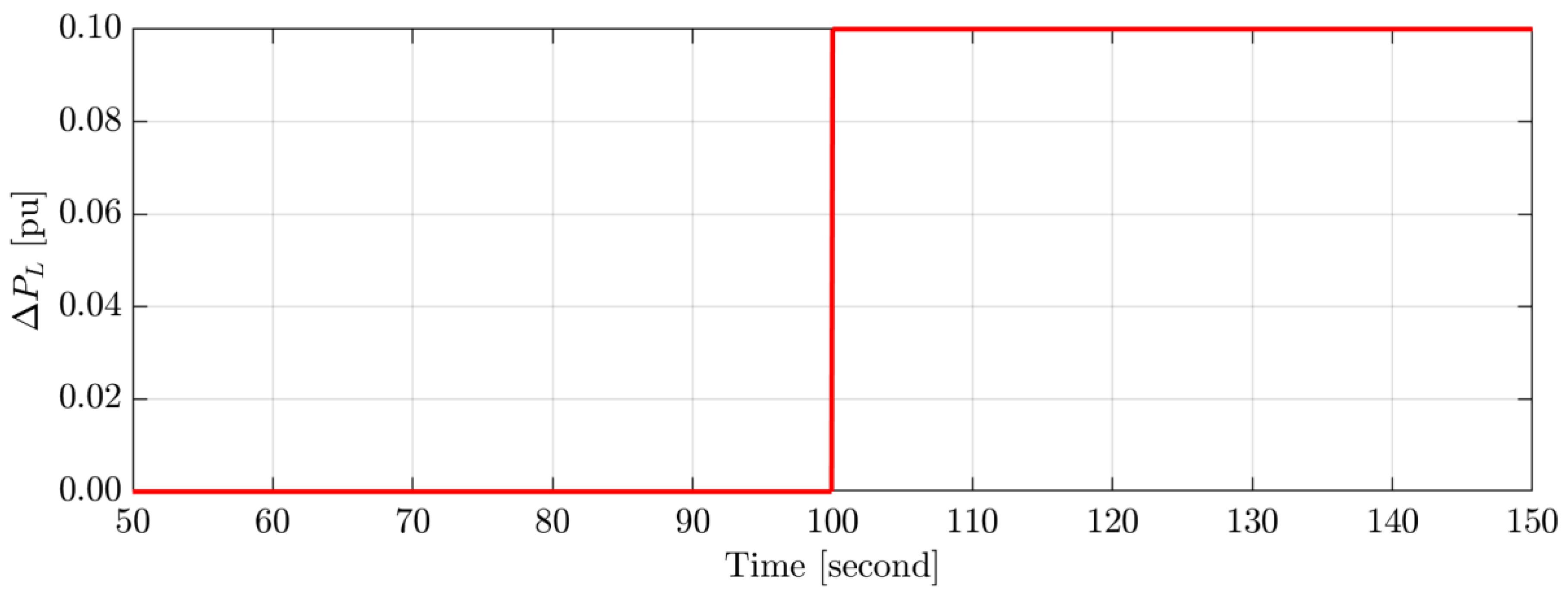
In this case, the efficacy of the proposed LFC based on the optimal intelligent integral controller-based AVOA was compared with the conventional LFC based on the integral controller under a 10% abrupt load change at t = 100 s, as shown in Figure 11. Figure 12 shows the frequency deviation of the studied system with both the proposed intelligent and conventional integral controllers. The simulation results demonstrate that when compared to the conventional LFC-based integral controller, the proposed intelligent integral controller based on the AVOA performs better. The proposed controller exhibits the best performance with fewer overshoots, fewer undershoots, and a quick settling time. In addition, the objective function obtained from the studied system, as shown in Figure 13, has demonstrated the superiority of the proposed control technique over the traditional control technique since it provides a minimum value.

4.2. Scenario B: System Performance Assessment under Random Load Change and Random Renewables Generation

Case 3: Impact of a stochastic load/RESs variation on system performance
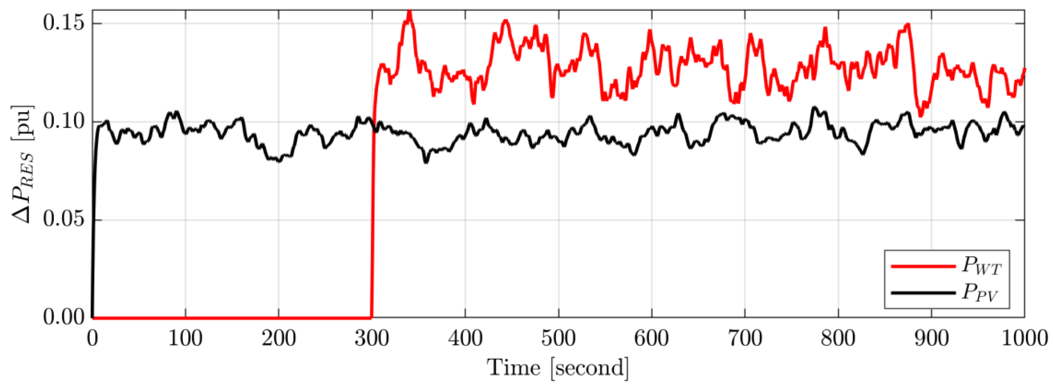
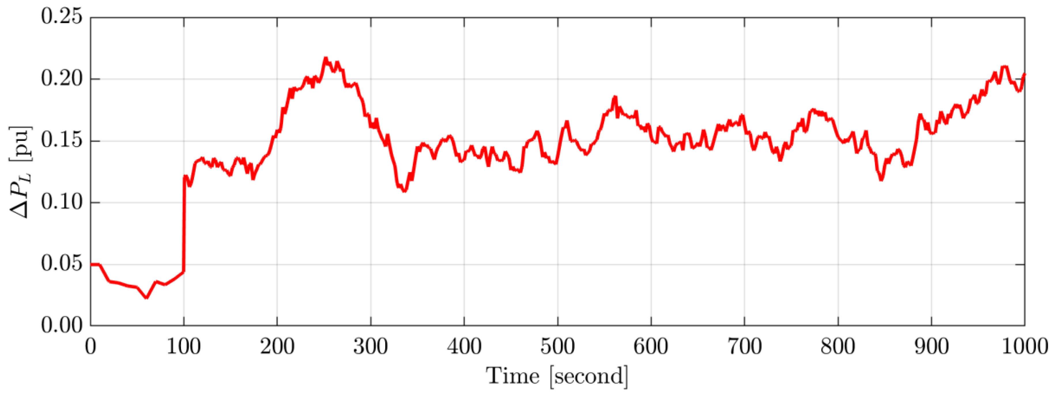
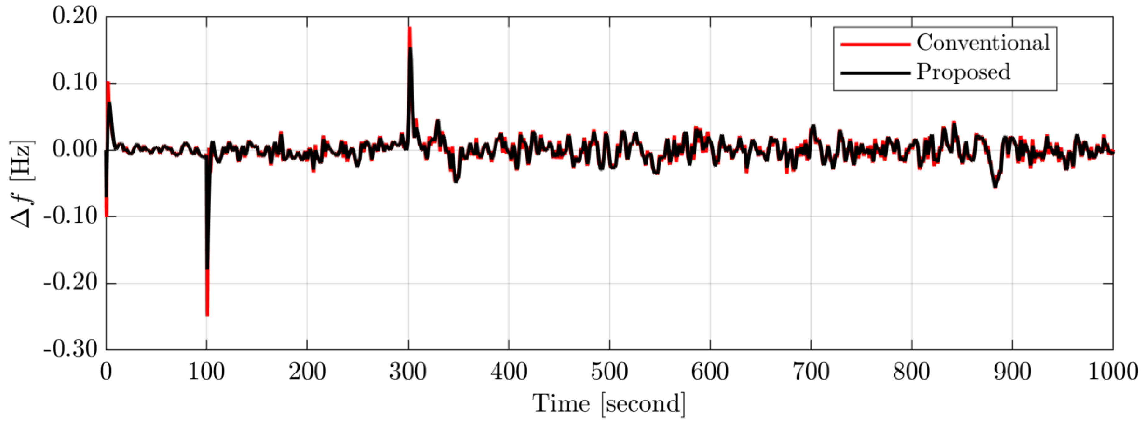
In this case study, the targeted islanded µG with the proposed intelligent integral controller based on the AVOA was examined with the variation of RESs generation shown in Figure 14, while the stochastic load variation shown in Figure 15. The simulation findings shown in Figure 16 demonstrate that, compared to employing the standard LFC based on the integral controller, the proposed intelligent integral controller based on the AVOA can dampen the frequency deviations caused by variations in high loads/RESs. Therefore, the proposed intelligent integral controller based on the AVOA provides superior performance in boosting the frequency stability of the investigated µG than using the conventional LFC-based integral controller described in the literature.
Case 4: Impact of stochastic generation of RESs and series of step load changes on system performance
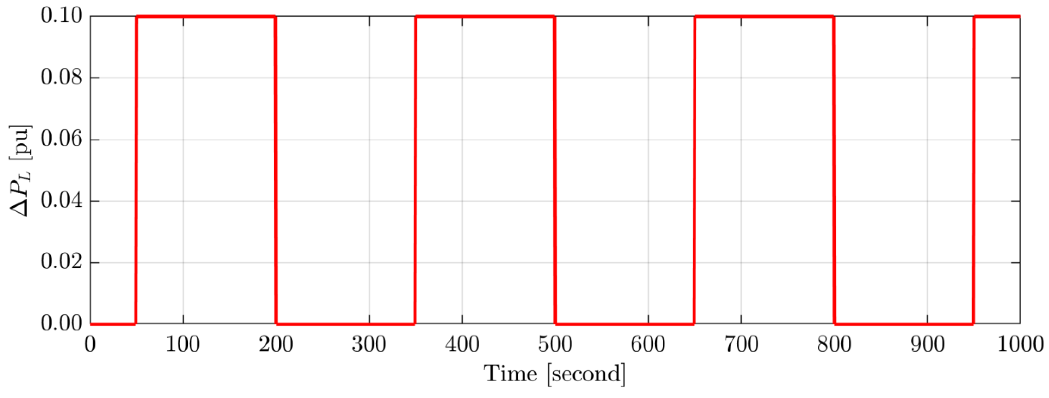
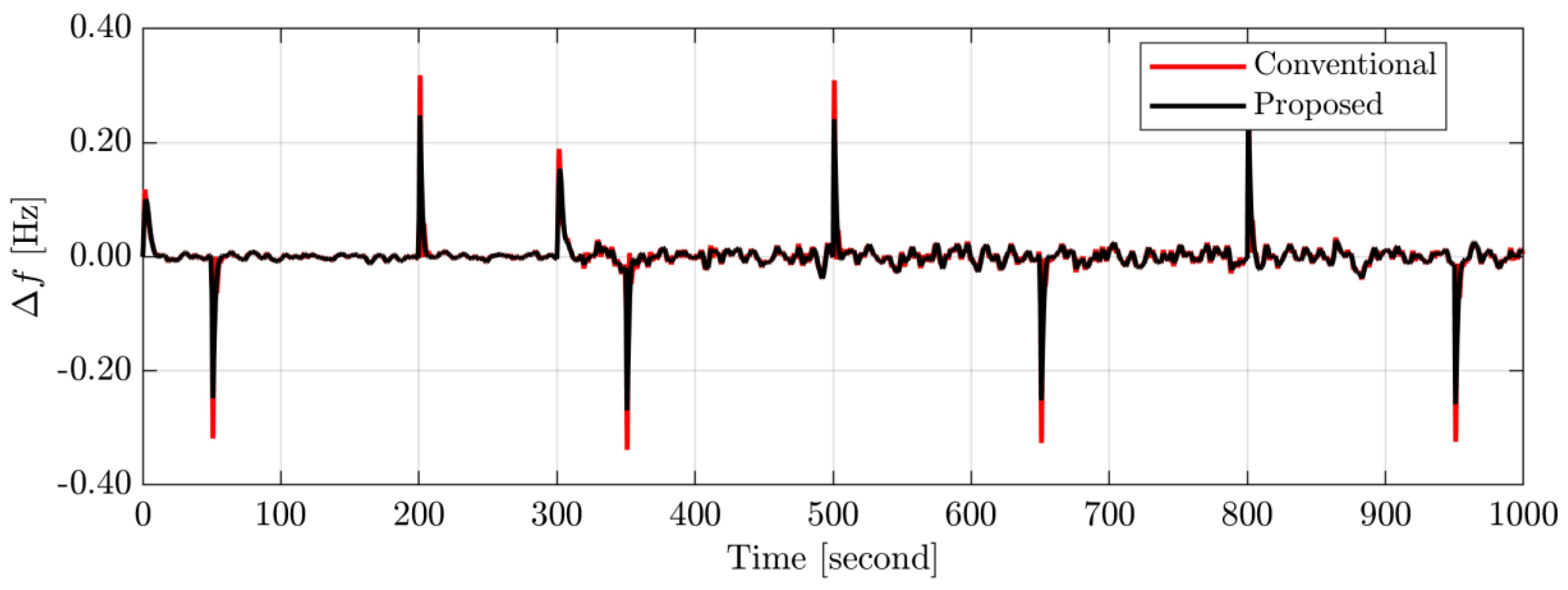
To validate the efficacy of the proposed intelligent integral controller based on the AVOA, the stochastic generation of RESs shown in Figure 14 and the random load variability shown in Figure 17 were introduced in the case study islanded µG. Figure 18 demonstrates the system frequency deviation with the proposed and conventional LFC techniques based on the integral controller. Figure 18 shows that the targeted islanded µG comprising RESs is more reliable and quicker with the proposed LFC based on the intelligent integral controller-based AVOA than with the conventional LFC based on the integral controller. Hence, the proposed LFC based on the intelligent integral controller can withstand the frequency deviation resulting from the stochastic generation of RESs and random load variations.

4.3. Scenario C: Long-Term Impact of Random Loads/RESs on System Performance

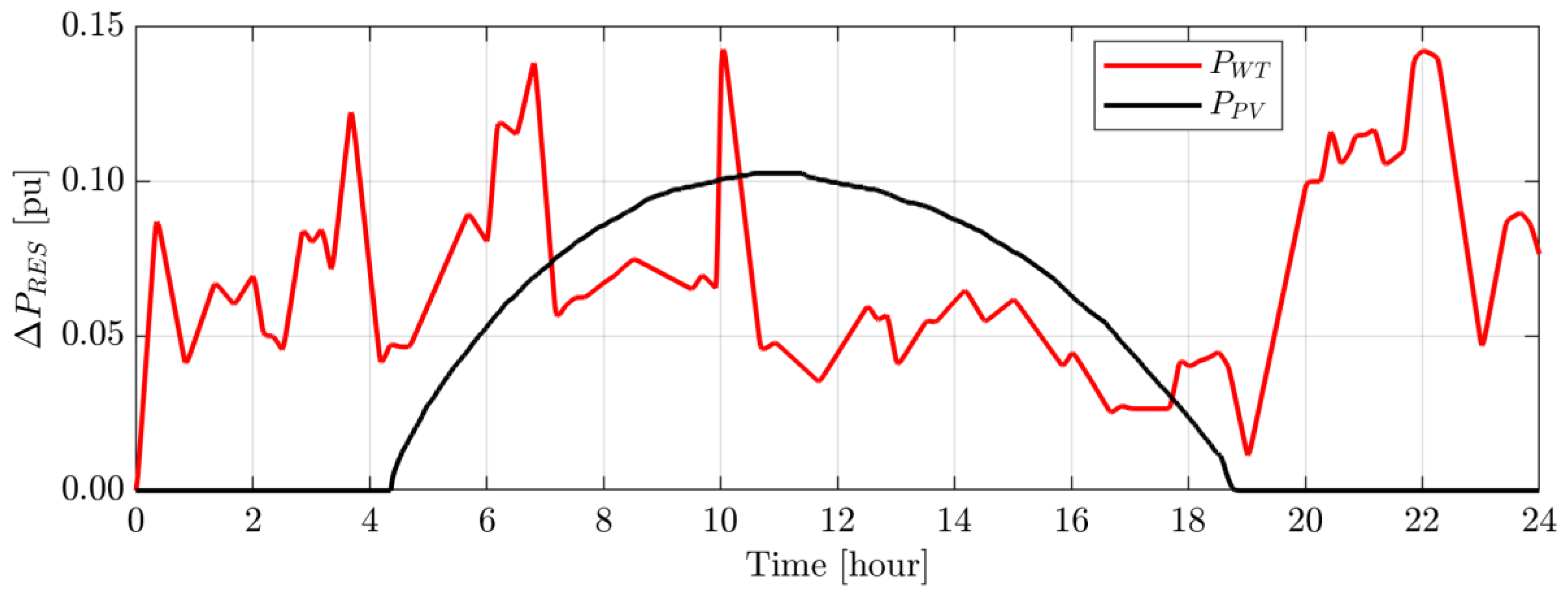
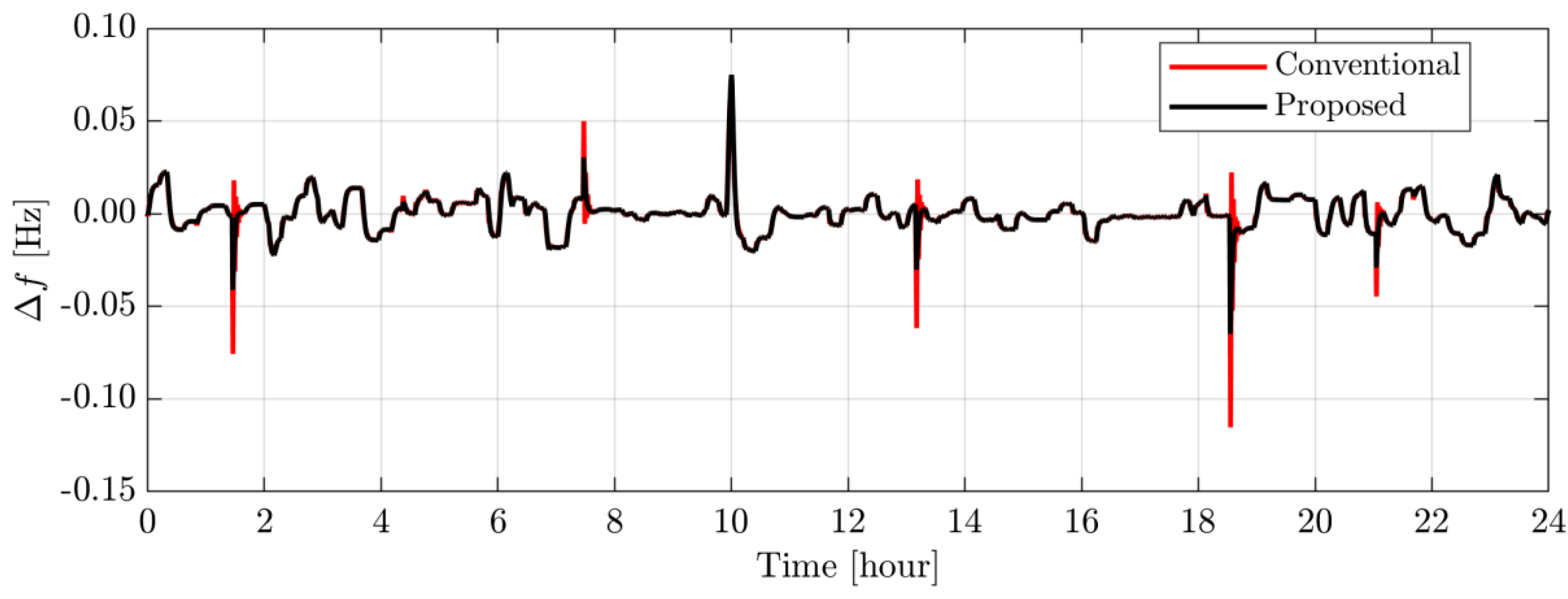
In this scenario, a stochastic RESs generation shown in Figure 19 and a random load change shown in Figure 20 were implemented for a long-term study (i.e., 24 h) to assess the efficacy and resilience of the proposed LFC technique based on intelligent integral controller-based AVOA. As evidence of the proposed control system’s performance, it was compared to the traditional LFC technique based on the integral controller. Figure 21 shows the frequency response of the cases study µG for the scenario C. It is important to notice from Figure 21 that the proposed LFC based on the intelligent integral controller-based AVOA makes the considered µG considering loads/RESs uncertainties more dependable and quicker than the traditional LFC system.

5. Conclusions

This paper proposed an optimal ULM control integrated with an integral secondary frequency controller, called an intelligent integral control, for the frequency stability enhancement of µGs considering high penetration of RESs. The ULM control parameter was tuned using a new optimization algorithm called the AVOA. The performance of the proposed intelligent controller was compared with the conventional LFC-based integral controller used in the literature through an islanded µGs considering a high penetration level of RESs. The case study µG comprises a small thermal power plant, PV, wind power plants, and residential and nonresidential loads. The simulation results indicated the superiority of the proposed control technique over the conventional control technique. It provides a 37% reduction in the system frequency variations, providing the minimum system objective function. Moreover, the proposed controller provides more power commands to the governor compared to the conventional controller. Hence, the proposed intelligent controller could improve the dynamic frequency performance in modern power systems with high renewable penetration and under different operating conditions.

Author Contributions

Conceptualization, A.B.; methodology, A.B. and G.M.; software, A.B. and G.M.; validation, A.B., G.M. and M.R.; formal analysis, A.B. and G.M.; investigation, A.B.; re-sources, G.M., F.J. and A.C.; data curation, M.R.; writing—original draft preparation, A.B., G.M. and M.R.; writing—review and editing, A.B., G.M., M.R., F.J. and A.C.; visualization, A.B., G.M. and M.R.; supervision, A.C. and F.J.; project administration, A.C.; funding acquisition, G.M. and A.C. All authors have read and agreed to the published version of the manuscript.

Funding

This research received no external funding.

Conflicts of Interest

The authors declare no conflict of interest.

Nomenclature

RESsRenewable energy sources
LFCLoad frequency control
ULMUltralocal model
µGMicrogrid
AVOAAfrican vultures optimization algorithm
PSPower systems
ESSsEnergy storage systems
PVPhotovoltaic
PIDProportional integral derivative
iPIDIntelligent proportional integral derivative
DGsDistributed generators
PPsPower plants
VUUpper limit
VLLower limit
GRCGeneration rate constraint
DMicrogrid damping coefficient (pu MW/Hz)
HMicrogrid inertia constant (pu MW s)
TgGovernor time constant (s)
TtTurbine time constant (s)
KIIntegral control gain
RSpeed regulation of μG, (Hz/pu MW)
TWTWind turbine time constant (s)
TPVPV system time constant (s)
fNominal frequency (Hz)
SSMState-space model
ΔfFrequency deviation (Hz)
ΔPWindWind speed change (pu)
ΔPSolarPV solar change (pu)
ΔPLLoad power change (pu)
PPVPV output power (pu)
PWTWind turbine output power (pu)
PCIncremental power (pu)
PmMechanical power change (pu)
PgGovernor power (pu)
ENonlinear unknown function
uControl input of the system
yOutput variable of the system
mOrder of the control input
nOrder of the system output
FSum of the known and unknown parameters of the system
αNonphysical parameter of ULM
sLaplace operator
TsSampling time
NfWindow length
y*Reference of the system output
eThe error between the desired and actual output
AVAfrican vultures
NNumber of vultures
L1,L2,rand3, rand4, rand5, rand6,v, uRandom numbers ranging from 0 and 1
FiThe rate of vulture satiation calculated in the current iteration
nTotal number of the first and second groups of vultures
zVariable of a random value ranging from −1 and 1
hVariable of a random value ranging from −2 and 2
ωA parameter with a predetermined value
R(i)One of the finest vultures determined in the current iteration
D(i)Distance between the vulture and the current optimum vulture
ubVariable upper boundary
LbVariable lower boundary
P(i)The location of the ith vulture
XRandom variable ranging from 0 and 2
d(t)The distance that separates the vulture and one of the two “best vultures” groups
LFLévy flight
βConstant

References

  1. Rihan, M.; Nasrallah, M.; Hasanin, B.; El-Shahat, A. A Proposed Controllable Crowbar for a Brushless Doubly-Fed Reluctance Generator, a Grid-Integrated Wind Turbine. Energies 2022, 15, 3894. [Google Scholar] [CrossRef]
  2. Murtaza, A.F.; Sher, H.A.; Usman Khan, F.; Nasir, A.; Spertino, F. Efficient MPP Tracking of Photovoltaic (PV) Array Through Modified Boost Converter With Simple SMC Voltage Regulator. IEEE Trans. Sustain. Energy 2022, 13, 1790–1801. [Google Scholar] [CrossRef]
  3. Bakeer, A.; Magdy, G.; Chub, A.; Bevrani, H. A sophisticated modeling approach for photovoltaic systems in load frequency control. Int. J. Electr. Power Energy Syst. 2022, 134, 107330. [Google Scholar] [CrossRef]
  4. Zakir, M.; Arshad, A.; Sher, H.A.; Lehtonen, M. An Optimal Power Management System Based on Load Demand and Resources Availability for PV Fed DC-Microgrid with Power-Sharing among Multiple Nanogrids. In Proceedings of the 2021 IEEE PES Innovative Smart Grid Technologies Europe (ISGT Europe), Espoo, Finland, 18–21 October 2021; IEEE: Piscataway, NJ, USA, 2021. [Google Scholar] [CrossRef]
  5. Nour, M.; Magdy, G.; Chaves-Ávila, J.P.; Sánchez-Miralles, Á.; Petlenkov, E. Automatic Generation Control of a Future Multisource Power System Considering High Renewables Penetration and Electric Vehicles: Egyptian Power System in 2035. IEEE Access 2022, 10, 51662–51681. [Google Scholar] [CrossRef]
  6. Sohrabzadi, E.; Gheisarnejad, M.; Esfahani, Z.; Khooban, M.H. A novel intelligent ultra-local model control-based type-II fuzzy for frequency regulation of multi-microgrids. Trans. Inst. Meas. Control 2021, 44, 1134–1148. [Google Scholar] [CrossRef]
  7. Tu, Z.; Fan, B.; Khazaei, J.; Zhang, W.; Liu, W. October. Optimal Reset-Control-Based Load Frequency Regulation in Isolated Microgrids. IEEE Trans. Sustain. Energy 2022, 13, 2239–2249. [Google Scholar] [CrossRef]
  8. Magdy, G.; Ali, H.; Xu, D. A new synthetic inertia system based on electric vehicles to support the frequency stability of low-inertia modern power grids. J. Clean. Prod. 2021, 297, 126595. [Google Scholar] [CrossRef]
  9. Jan, M.U.; Xin, A.; Rehman, H.U.; Abdelbaky, M.A.; Iqbal, S.; Aurangzeb, M. Frequency Regulation of an Isolated Microgrid With Electric Vehicles and Energy Storage System Integration Using Adaptive and Model Predictive Controllers. IEEE Access 2021, 9, 14958–14970. [Google Scholar] [CrossRef]
  10. Farrokhabadi, M.; Cañizares, C.A.; Bhattacharya, K. Frequency Control in Isolated/Islanded Microgrids Through Voltage Regulation. IEEE Trans. Smart Grid. 2017, 8, 1185–1194. [Google Scholar] [CrossRef]
  11. Ali, H.; Magdy, G.; Xu, D. A new optimal robust controller for frequency stability of interconnected hybrid microgrids considering non-inertia sources and uncertainties. Int. J. Electr. Power Energy Syst. 2021, 128, 106651. [Google Scholar] [CrossRef]
  12. Sibtain, D.; Murtaza, A.F.; Ahmed, N.; Sher, H.A.; Gulzar, M.M. Multi control adaptive fractional order PID control approach for PV/wind connected grid system. Int. Trans. Electr. Energy Syst. 2021, 31, e12809. [Google Scholar] [CrossRef]
  13. El-Fergany, A.A.; El-Hameed, M.A. Efficient frequency controllers for autonomous two-area hybrid microgrid system using social-spider optimiser. IET Gener. Trans. Distrib. 2017, 11, 637–648. [Google Scholar] [CrossRef]
  14. Khooban, M.H.; Gheisarnejad, M. A Novel Deep Reinforcement Learning Controller Based Type-II Fuzzy System: Frequency Regulation in Microgrids. IEEE Trans. Emergy Top. Comput. Intell. 2020, 5, 689–699. [Google Scholar] [CrossRef]
  15. Aluko, A.O.; Dorrell, D.G.; Pillay-Carpanen, R.; Ojo, E.E. Frequency Control of Modern Multi-Area Power Systems Using Fuzzy Logic Controller. In Proceedings of the 2019 IEEE PES/ IAS PowerAfrica, Abuja, Nigeria, 20–23 August 2019; pp. 645–649. [Google Scholar] [CrossRef]
  16. Liao, K.; Xu, Y. A Robust Load Frequency Control Scheme for Power Systems Based on Second-Order Sliding Mode and Extended Disturbance Observer. IEEE Trans. Ind. Inform. 2018, 14, 3076–3086. [Google Scholar] [CrossRef]
  17. Magdy, G.; Ali, H.; Xu, D. Effective control of smart hybrid power systems: Cooperation of robust LFC and virtual inertia control system. CSEE J. Power Energy Systems 2022, 8, 1583–1593. [Google Scholar] [CrossRef]
  18. Bevrani, H.; Feizi, M.R.; Ataee, S. Robust Frequency Control in an Islanded Microgrid: H and μ-Synthesis Approaches. IEEE Trans. Smart Grid. 2016, 7, 706–717. [Google Scholar] [CrossRef] [Green Version]
  19. Ma, M.; Liu, X.; Zhang, C. LFC for multi-area interconnected power system concerning wind turbines based on DMPC. IET Gener. Trans. Distrib. 2017, 11, 2689–2696. [Google Scholar] [CrossRef]
  20. Liu, T.; Chen, A.; Gao, F.; Liu, X.; Li, X.; Hu, S. Double-Loop Control Strategy With Cascaded Model Predictive Control to Improve Frequency Regulation for Islanded Microgrids. IEEE Trans. Smart Grid. 2022, 13, 3954–3967. [Google Scholar] [CrossRef]
  21. Magdy, G.; Shabib, G.; Elbaset, A.A.; Mitani, Y. A Novel Coordination Scheme of Virtual Inertia Control and Digital Protection for Microgrid Dynamic Security Considering High Renewable Energy Penetration. IET Renew. Power Gener. 2019, 13, 462–474. [Google Scholar] [CrossRef]
  22. Magdy, G.; Bakeer, A.; Nour, M.; Petlenkov, E. A New Virtual Synchronous Generator Design Based on the SMES System for Frequency Stability of Low-Inertia Power Grids. Energies 2020, 13, 5641. [Google Scholar] [CrossRef]
  23. Kerdphol, T.; Rahman, F.S.; Mitani, Y.; Watanabe, M.; Küfeoǧlu, S.K. Robust Virtual Inertia Control of an Islanded Microgrid Considering High Penetration of Renewable Energy. IEEE Access 2018, 6, 625–636. [Google Scholar] [CrossRef]
  24. Fliess, M.; Join, C. Model-free control and intelligent pid controllers: Towards a possible trivialization of nonlinear control? IFAC Proc. Vol. 2009, 42, 1500–1531. [Google Scholar] [CrossRef] [Green Version]
  25. Michel, L.; Join, C.; Fliess, M.; Sicard, P.; Chériti, A. Model-free control of dc/dc converters. In Proceedings of the 2010 IEEE 12th Workshop on Control and Modeling for Power Electronics (COMPEL), Boulder, CO, USA, 28–30 June 2010; pp. 1–8. [Google Scholar] [CrossRef] [Green Version]
  26. Thabet, H.; Ayadi, M.; Rotella, F. Experimental comparison of new adaptive PI controllers based on the ultra-local model parameter identification. Int. J. Control Autom. Syst. 2016, 14, 1520–1527. [Google Scholar] [CrossRef] [Green Version]
  27. Zhang, Y.; Liu, X.; Liu, J.; Rodriguez, J.; Garcia, C. Model-free predictive current control of power converters based on ultra-local model. In Proceedings of the 2020 IEEE International Conference on Industrial Technology (ICIT), Buenos Aires, Argentina, 26–28 February 2020; pp. 1089–1093. [Google Scholar] [CrossRef]
  28. Magdy, G.; Bakeer, A.; Alhasheem, M. Superconducting energy storage technology-based synthetic inertia system control to enhance frequency dynamic performance in microgrids with high renewable penetration. Prot. Control Mod. Power Syst. 2021, 6, 36. [Google Scholar] [CrossRef]
  29. Ghazi, G.A.; Hasanien, H.M.; Al-Ammar, E.A.; Turky, R.A.; Ko, W.; Park, S.; Choi, H.-J. African Vulture Optimization Algorithm-Based PI Controllers for Performance Enhancement of Hybrid Renewable-Energy Systems. Sustainability 2022, 14, 8172. [Google Scholar] [CrossRef]
  30. Abdollahzadeh, B.; Gharehchopogh, F.S.; Mirjalili, S. African vultures optimization algorithm: A new nature-inspired metaheuristic algorithm for global optimization problems. Comput. Ind. Eng. 2021, 158, 107408. [Google Scholar] [CrossRef]
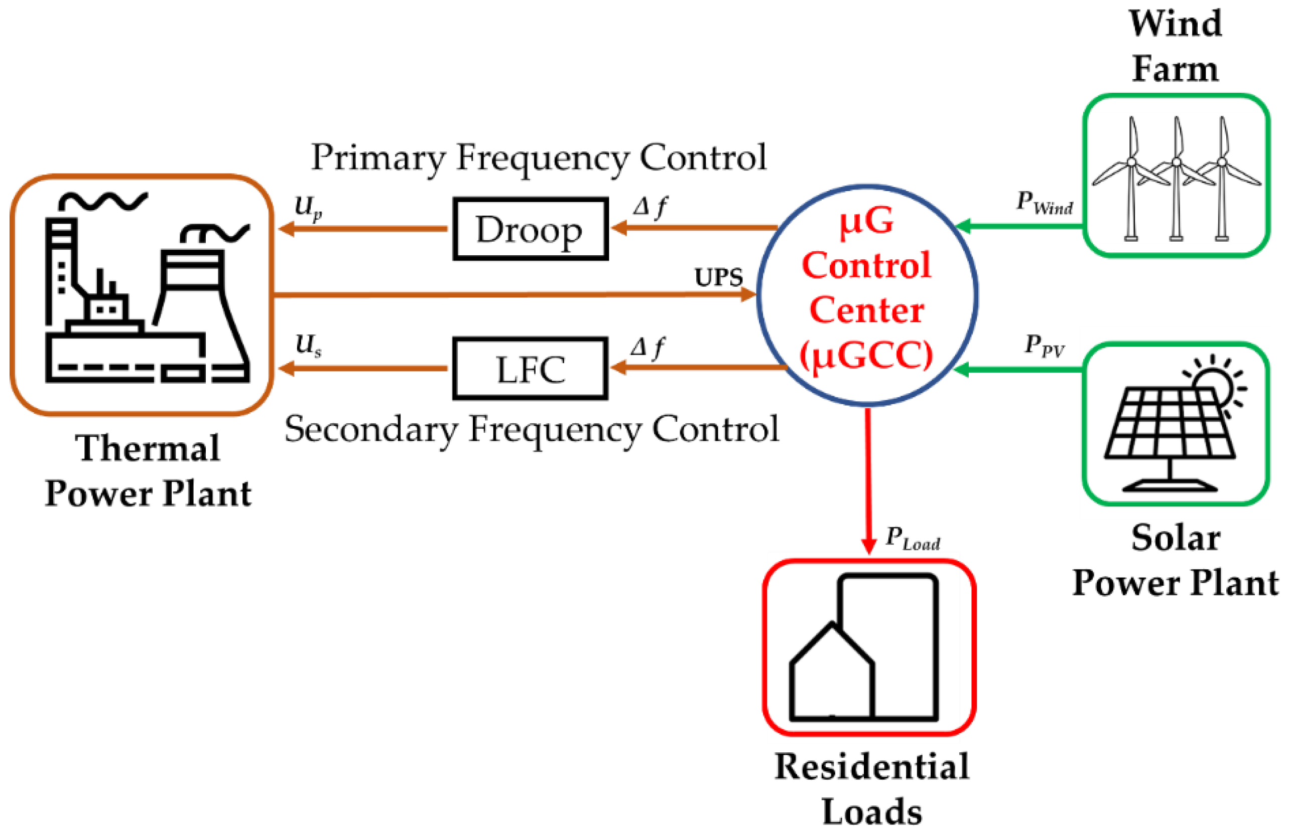
Figure 1. The layout diagram of the studied islanded µG.
Energies 15 09177 g001
Figure 2. A dynamic model of the studied µG with the proposed ULM incorporated into the secondary controller.
Energies 15 09177 g002
Figure 3. Structure of the ultra-local model.
Energies 15 09177 g003
Figure 4. Structure of the proposed optimal ULM incorporated with the integral controller for LFC of µG.
Energies 15 09177 g004
Figure 5. The AVOA flow chart.
Energies 15 09177 g005
Figure 6. Sudden load change for the case 1.
Energies 15 09177 g006
Figure 7. System frequency deviation of the studied µG for the case 1.
Energies 15 09177 g007
Figure 8. The ULM parameter (F) for the studied system’s inputs and outputs.
Energies 15 09177 g008
Figure 9. The output signals of the applied control techniques for the case 1.
Energies 15 09177 g009
Figure 10. The ISE objective functions of the studied system for the case 1.
Energies 15 09177 g010
Figure 11. Sudden load change for the case 2.
Energies 15 09177 g011
Figure 12. System frequency deviation of the studied µG for the case 2.
Energies 15 09177 g012
Figure 13. The system’s ISE objective function of the studied system for the case 2.
Energies 15 09177 g013
Figure 14. Wind and solar PV power profiles for the scenario B.
Energies 15 09177 g014
Figure 15. Random load change for the case 3.
Energies 15 09177 g015
Figure 16. System frequency deviation of the studied µG for the case 3.
Energies 15 09177 g016
Figure 17. Series of step load change for the case 4.
Energies 15 09177 g017
Figure 18. System frequency deviation of the studied µG for the case 4.
Energies 15 09177 g018
Figure 19. Wind and solar PV power profiles for long-term study for the scenario C.
Energies 15 09177 g019
Figure 20. Random load change for the long-term study for the scenario C.
Energies 15 09177 g020
Figure 21. System frequency deviation of the studied µG for the scenario C.
Energies 15 09177 g021
Table 1. Dynamic variables of the studied µG.
VariableValueVariableValue
D0.015TWT1.5
H0.083TPV1.8
Tg0.1VU0.3
Tt0.4VL−0.3
Ki0.05GRC20%
R2.4f50
Publisher’s Note: MDPI stays neutral with regard to jurisdictional claims in published maps and institutional affiliations.