

Mechanical Stress in Rotors of Permanent Magnet Machines—Comparison of Different Determination Methods


Abstract

1. Introduction
2. Materials and Methods
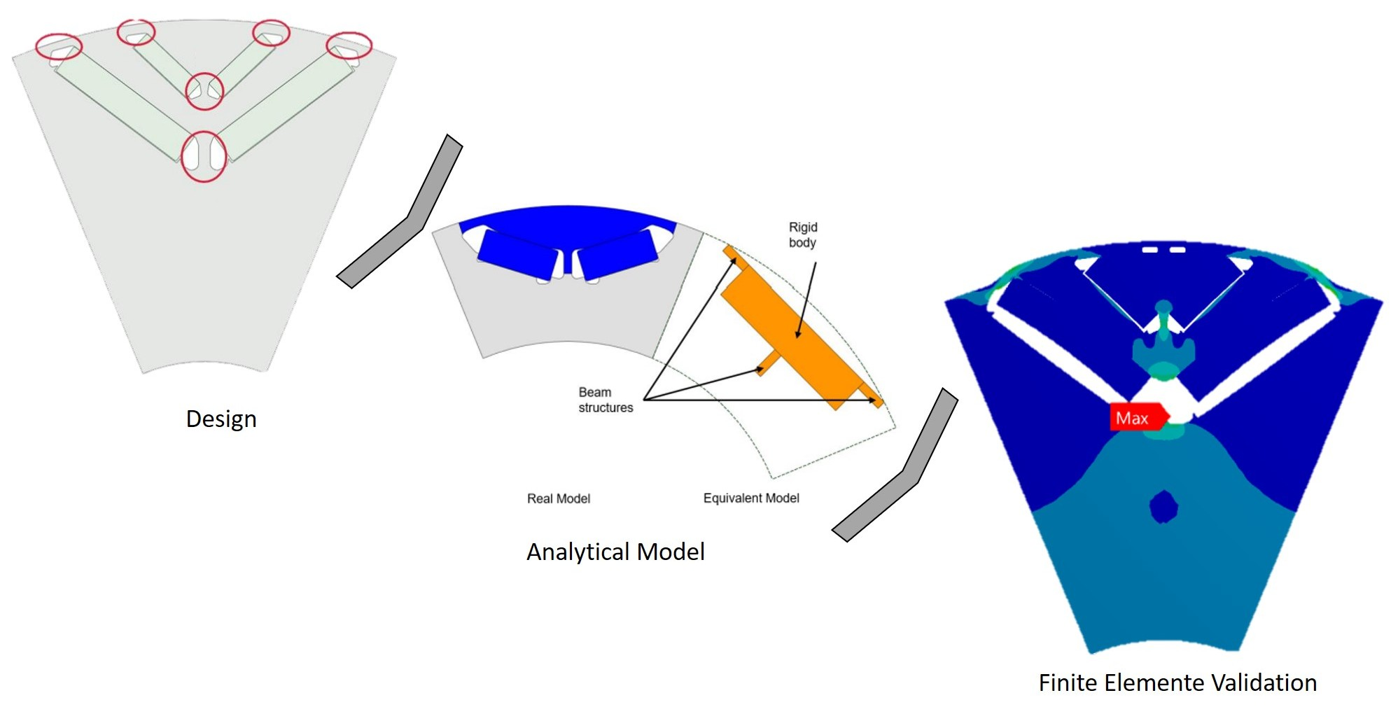
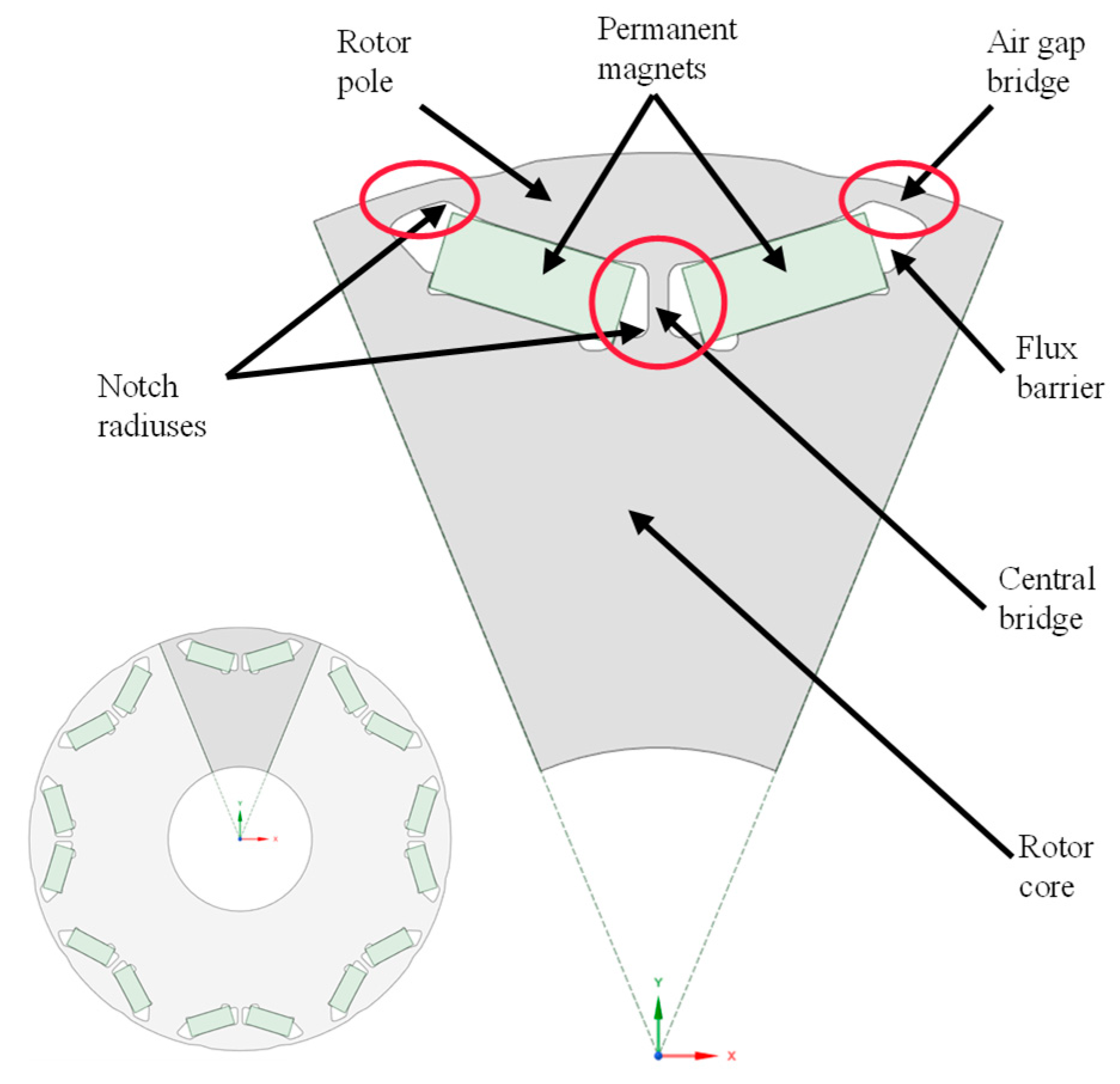
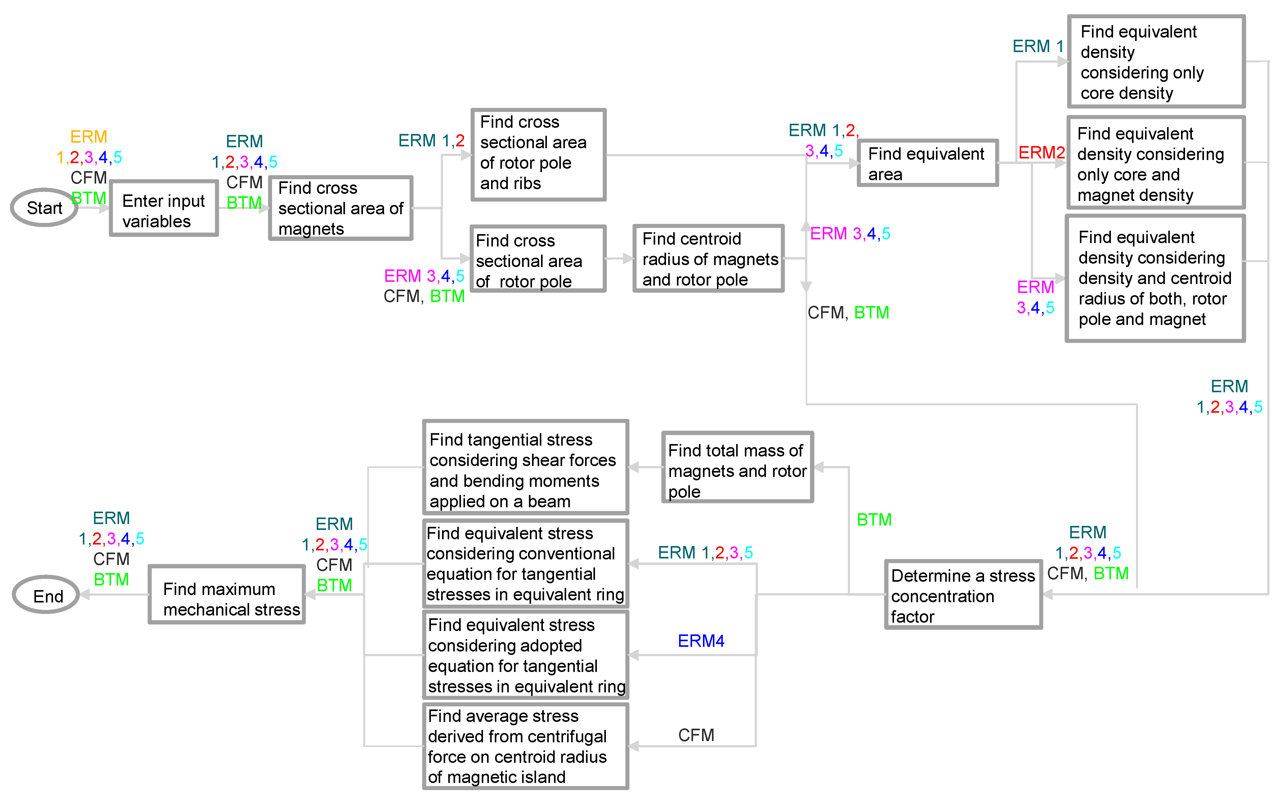
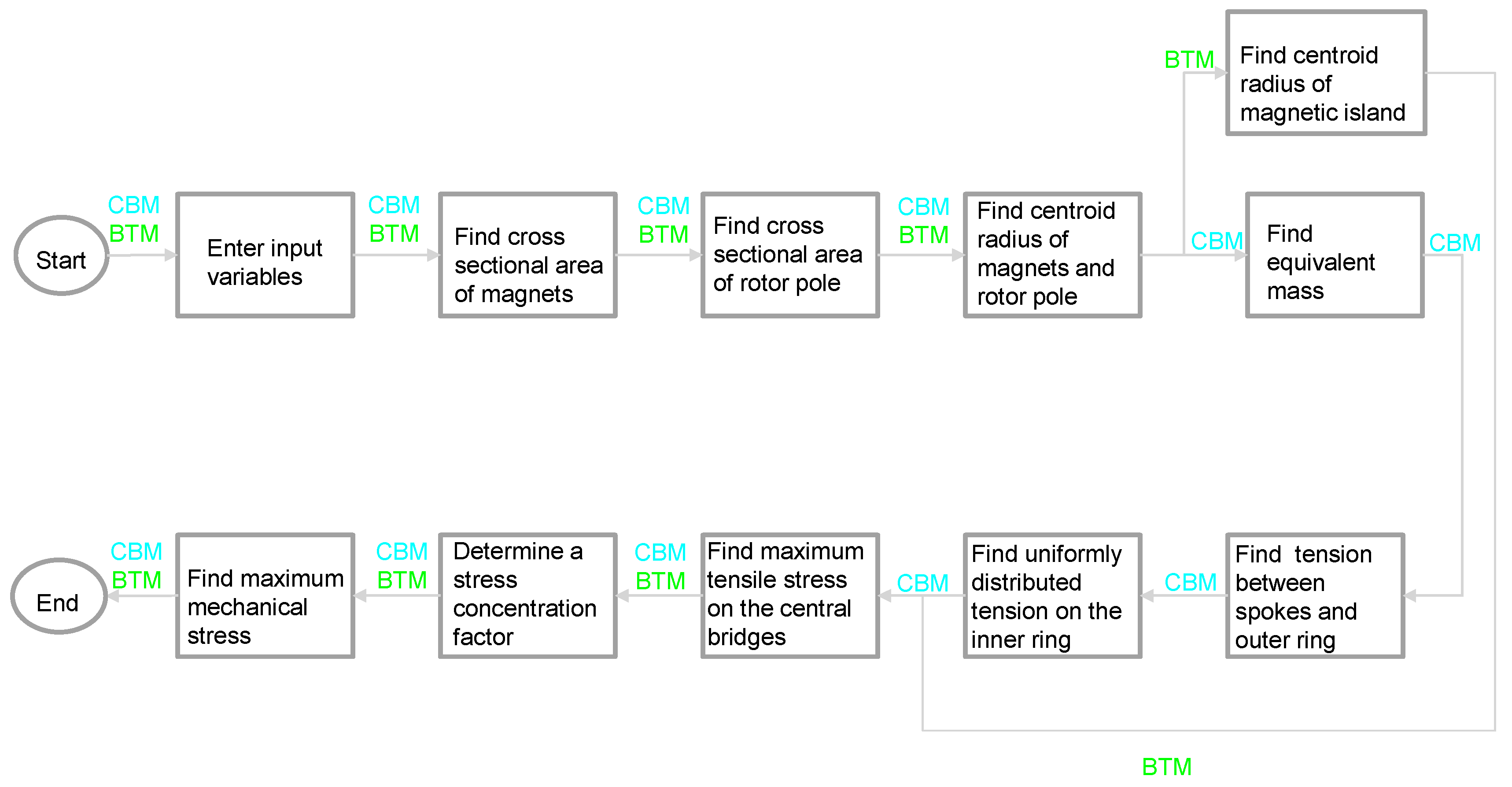
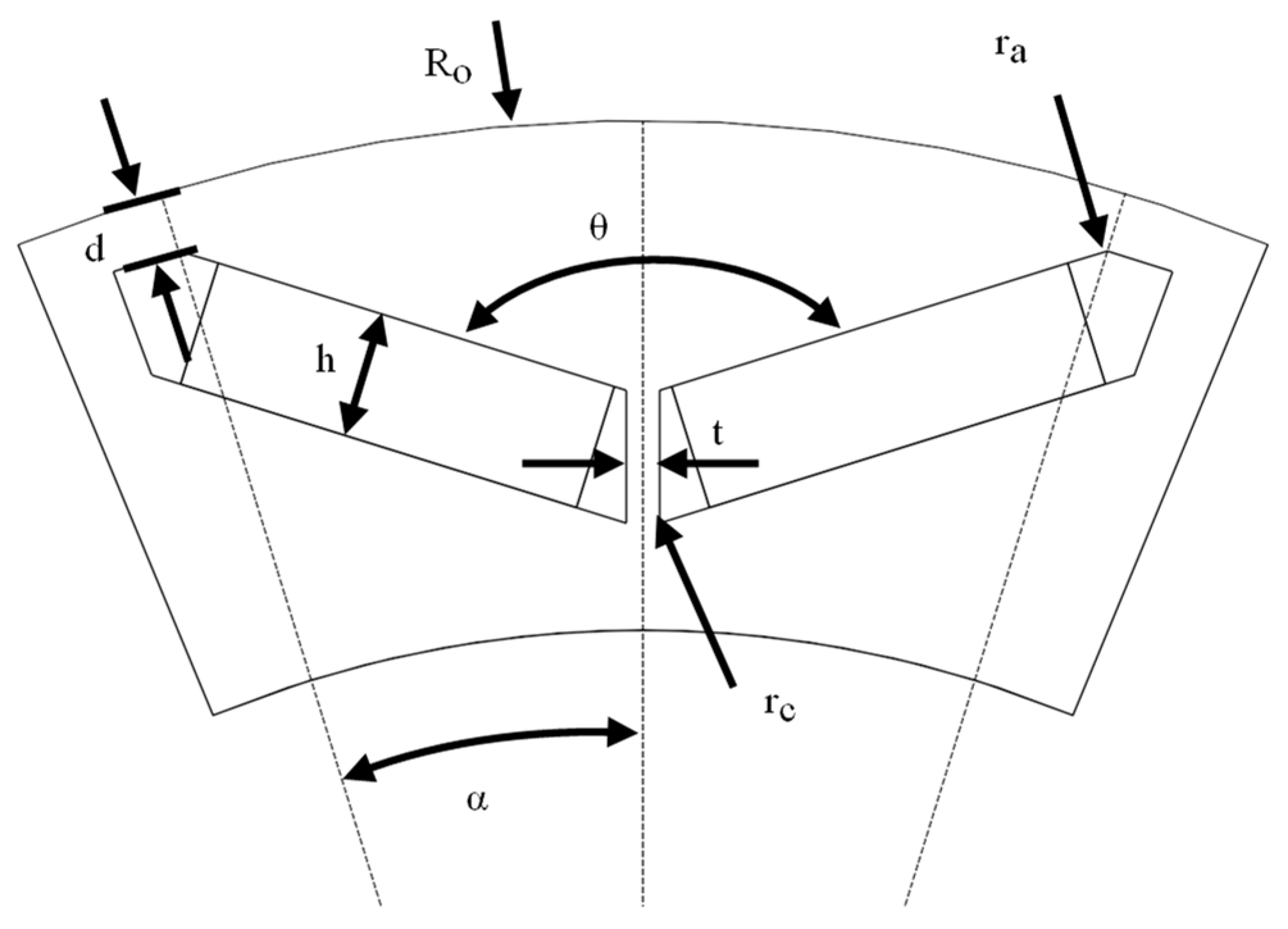
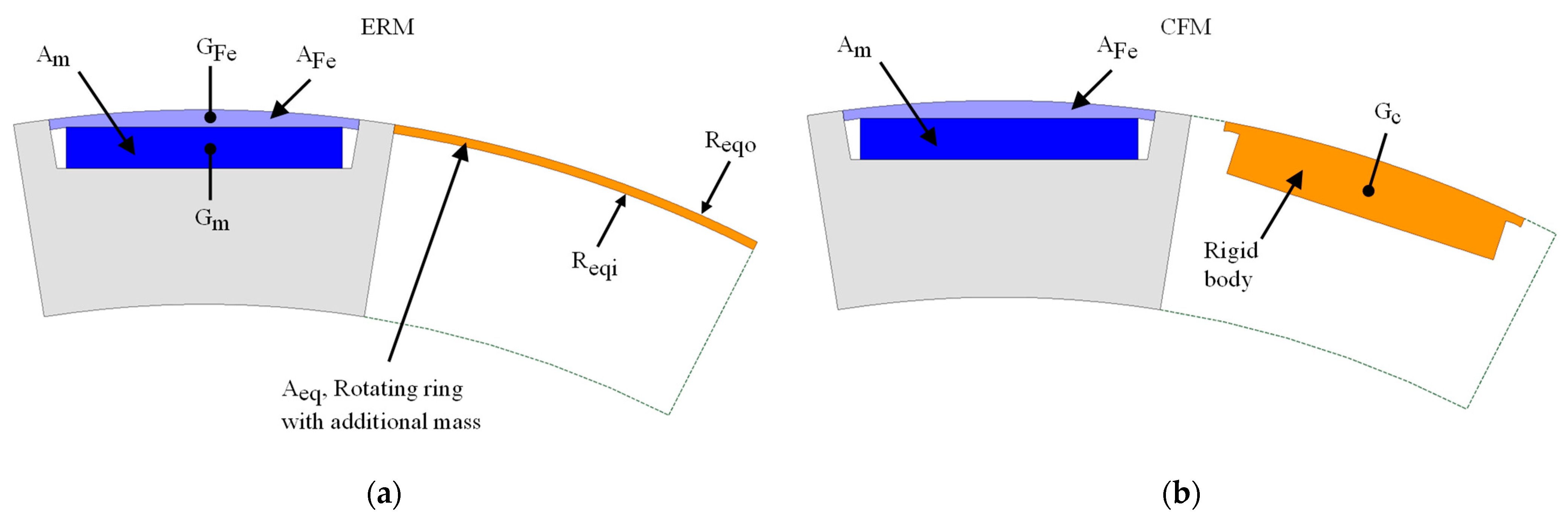
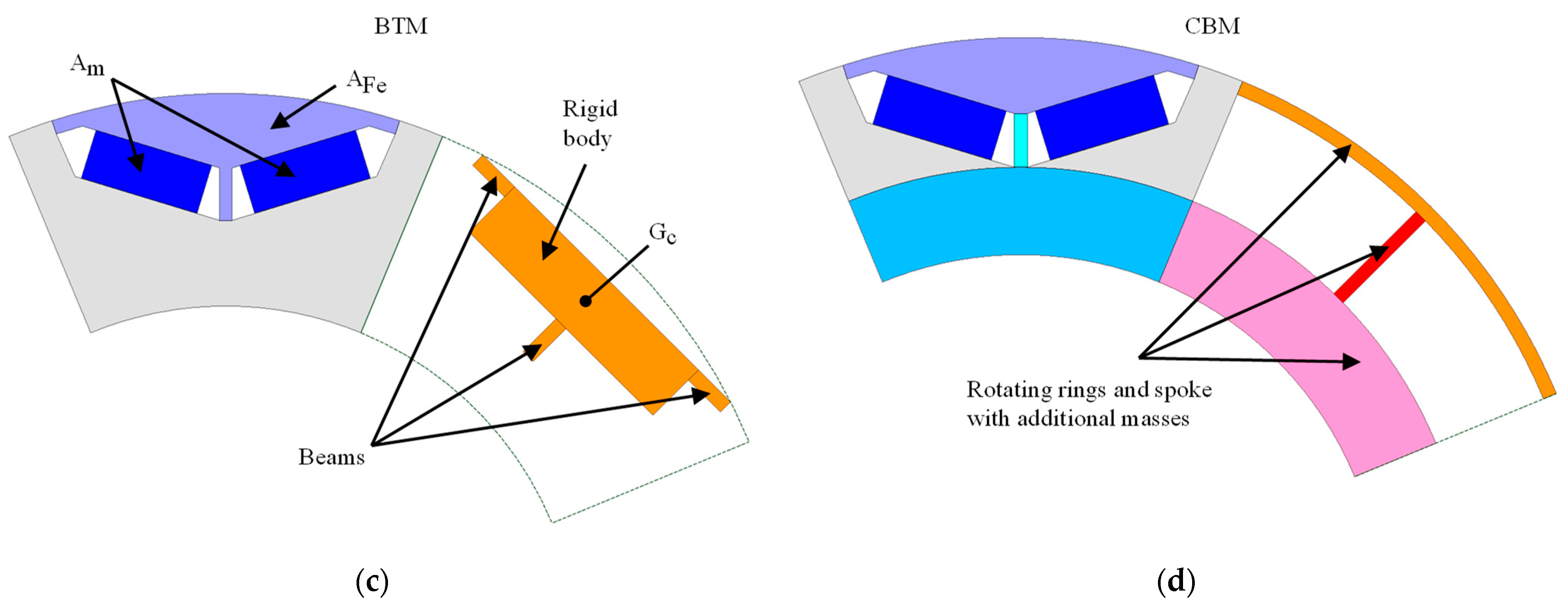
2.1. Analytical Methods to Determine the Maximum Mechanical Stress at the Air Gap Bridge and the Central Bridge
2.2. Determination of Stress Concentration Factors
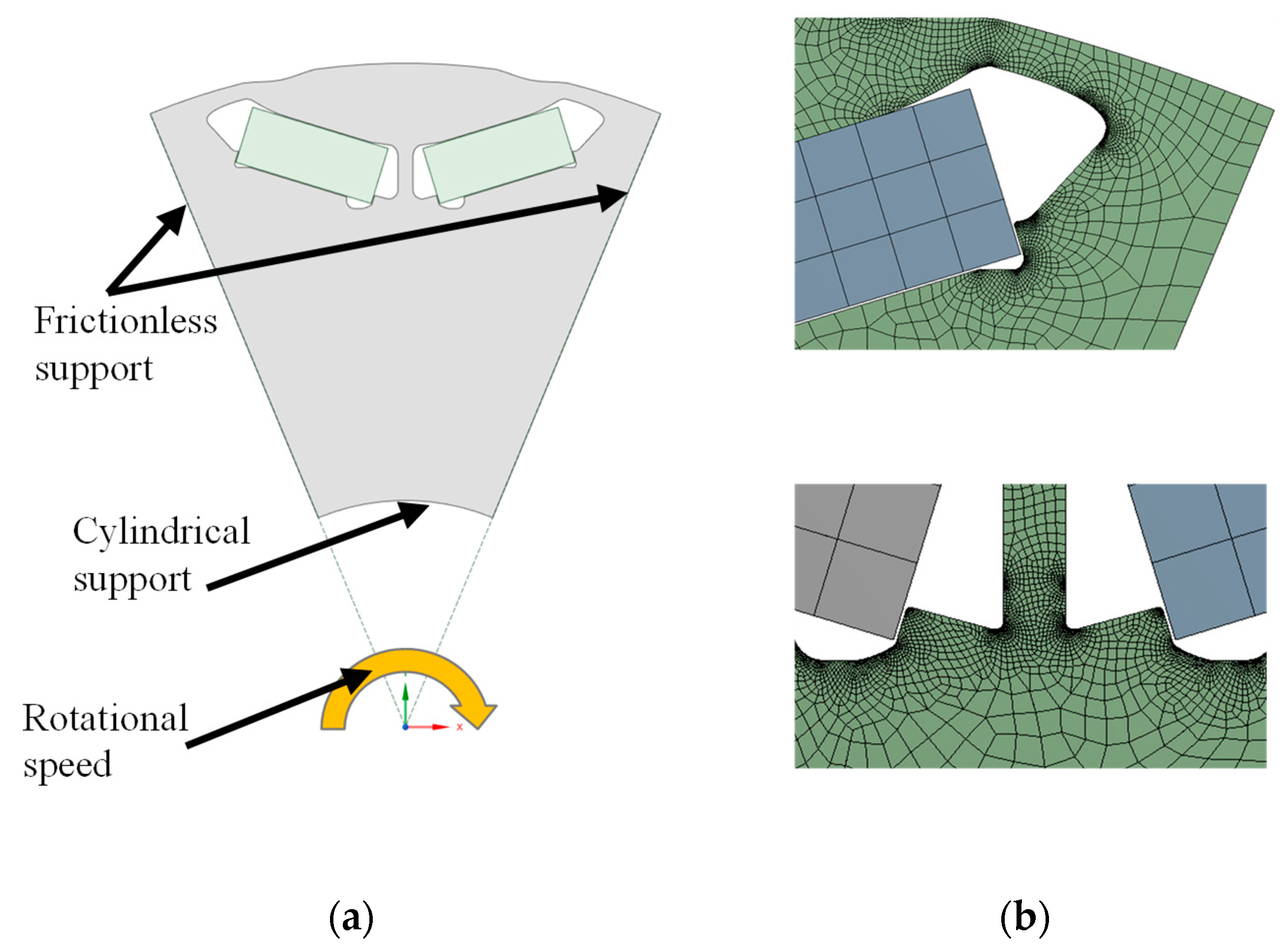
2.3. Initial Conditions and Assumptions
- Constant speed in steady state operation is assumed.
- Maximum deformation and stresses are mainly caused by centrifugal forces. The effect of electromagnetic forces between rotor and stator, and attraction forces between the permanent magnets and the rotor are considered negligible compared to centrifugal forces.
- Thermal effects are neglected.
- One pole in a two-dimensional model is used.
- The rotor core is assumed as an entity, and the lamination effects are considered negligible.
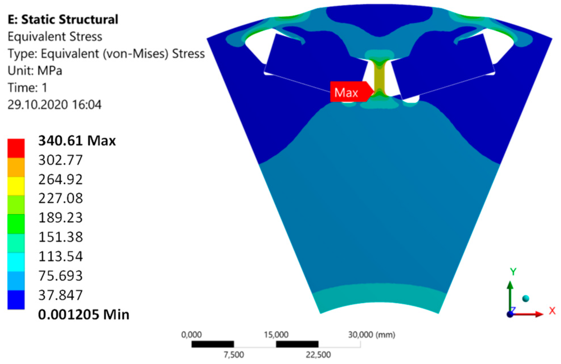
- Yield indicated by planar von Mises stress.
- The eccentricity of the rotor, the vibration, and the dynamic forces of the shaft are neglected.
- The analytical and numerical methods are based on the mono dimensional elastic theory. The inaccuracy of the methods proposed in this study increases with the mechanical stress above the yield point.
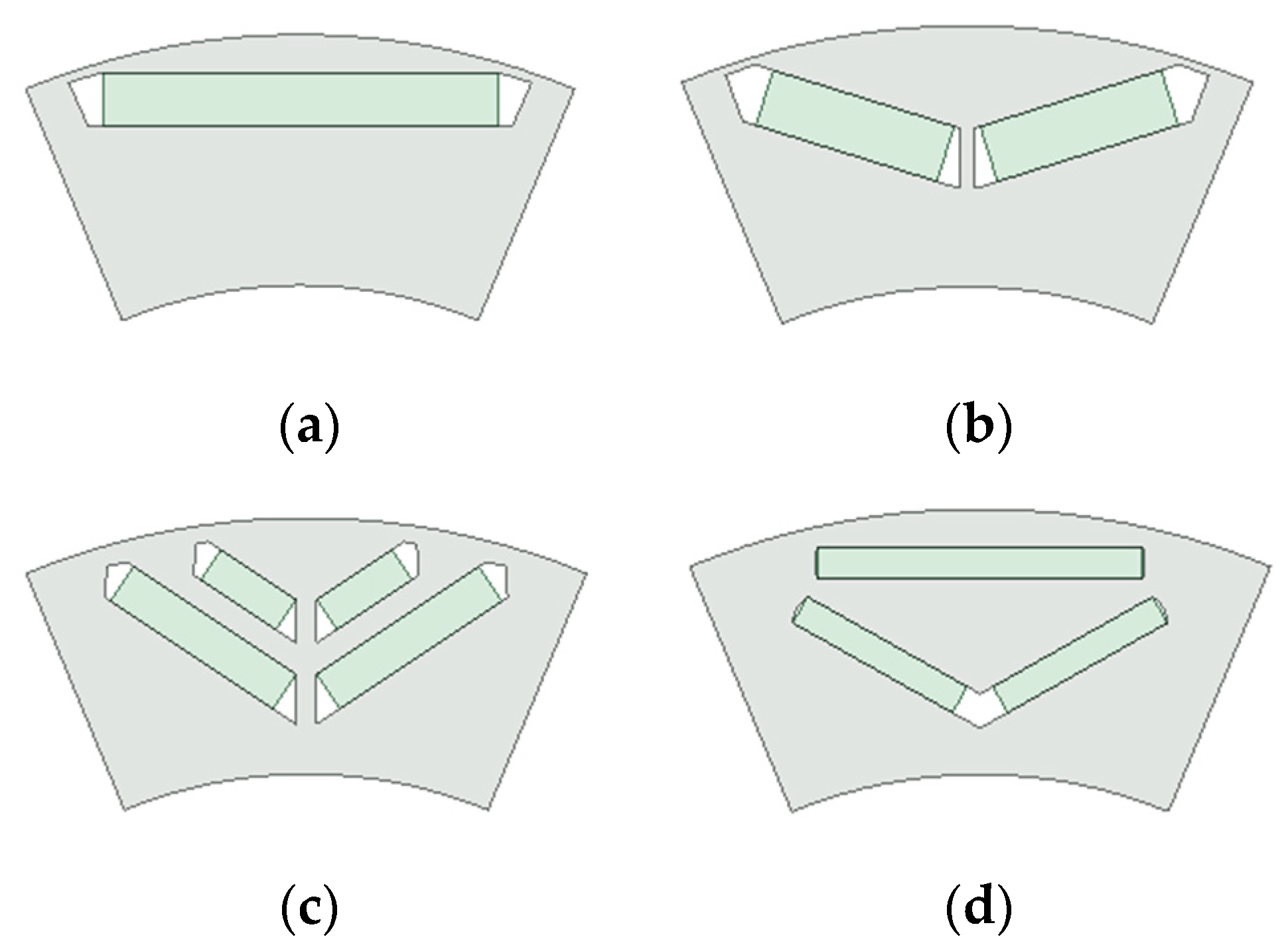
2.4. Investigated Machines
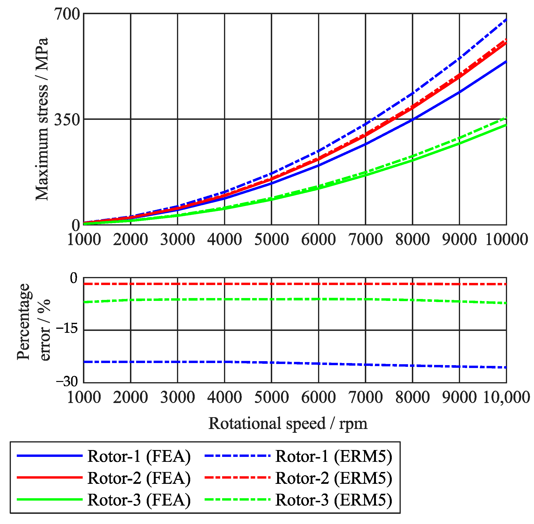
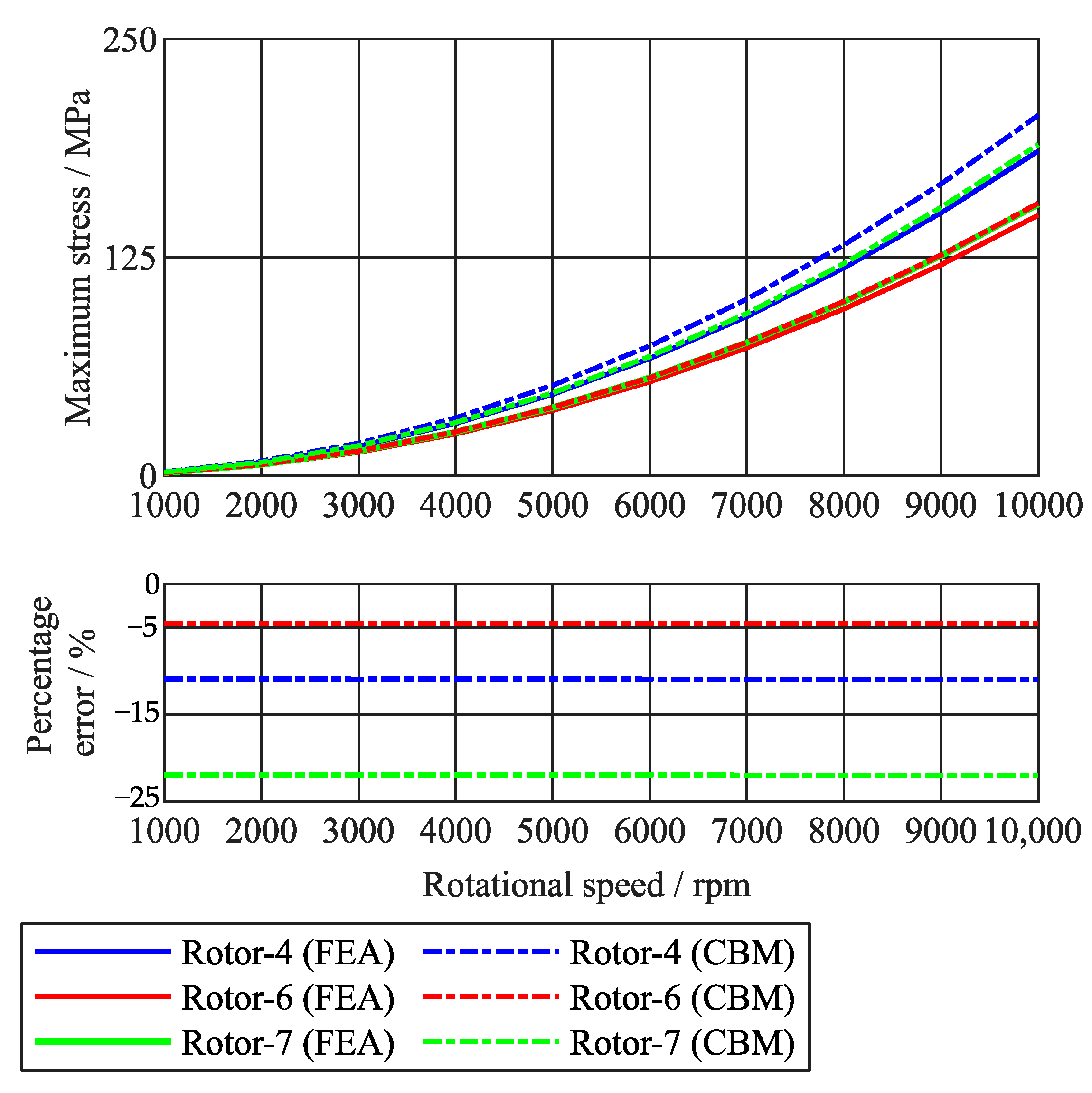
3. Performance Review of the Methods and Results
4. Conclusions
Author Contributions
Funding
Data Availability Statement
Conflicts of Interest
List of Symbols
| , | Mass density of electric steel and magnet material |
| Density of equivalent ring | |
| , , | Cross-sectional area of rotor pole, permanent magnets and equivalent ring |
| , | Tangential and maximum stresses inside equivalent ring |
| , | Outer and inner radiuses of equivalent ring |
| Rotational speed | |
| , | Stress concentration factor at the air gap and central bridges |
| , , | Center of gravity of rotor pole, magnets and rotor pole with magnets |
| , , | Centroid radius of rotor pole, magnets and equivalent ring |
| Angle between two magnets of a single pole | |
| Poisson’s ratio | |
| Centroid radius of rotor pole with magnets | |
| , | Air gap and central bridge thicknesses |
| Half pole arc | |
| , , | Constant coefficients for the relationship between centrifugal force, normal force and bending moment |
| Total mass of rotor pole with magnets | |
| Stack length | |
| Radial cross-sectional area of spokes | |
| Uniformly distributed tension on the inner ring | |
| Tension between spokes and outer ring | |
| , | Inner and outer radii of spokes |
| Spokes average weight per unit | |
| Uniformly distributed inertial load gravitational acceleration | |
| Number of spokes | |
| Young’s modulus | |
| Gravitational acceleration | |
| Flexibility coefficient of outer ring | |
| Centerline radius of inner ring | |
| , , | Cross-sectional areas of outer ring, inner ring and spokes |
| , | Notch radius on the air gap and central bridges |
References
- Krings, A.; Monissen, C. Review and Trends in Electric Traction Motors for Battery Electric and Hybrid Vehicles. In Proceedings of the 2020 International Conference on Electrical Machines (ICEM), Gothenburg, Sweden, 23–26 August 2020; pp. 1807–1813. [Google Scholar]
- Burress, T. Electrical Performance, Reliability Analysis, and Characterization. Available online: https://www.energy.gov/sites/prod/files/2017/06/f34/edt087_burress_2017_o.pdf (accessed on 10 November 2020).
- CORPORATION TM. The Evolution of the Prius [Internet]. Toyota Motor Corporation Official Global Website. Available online: http://global.toyota/en/detail/17852348 (accessed on 10 November 2022).
- Lee, K.J.; Kim, K.C.; Lee, J. Bridge optimization of interior permanent magnet motor for hybrid electric vehicle. In Proceedings of the 2003 IEEE International Magnetics Conference (INTERMAG), Boston, MA, USA, 30 March 2003–3 April 2003; p. GQ-07. [Google Scholar]
- Lovelace, E.C.; Jahns, T.M.; Keim, T.A.; Lang, J.H. Mechanical design considerations for conventionally laminated, high-speed, interior PM synchronous machine rotors. IEEE Trans. Ind. Appl. 2004, 40, 806–812. [Google Scholar] [CrossRef]
- Powercore® for High Frequencies and e-Mobility [Internet]. Thyssenkrupp. Available online: https://www.thyssenkrupp-steel.com/en/products/electrical-steel/electrical-steel-non-grain-oriented/powercore-for-high-frequencies-and-e-mobility/powercore-a-3.html (accessed on 23 November 2022).
- High-Strength Electrical Steel Strip: HS Grades for High Mechanical Stress [Internet]. Waelzholz. Available online: https://www.waelzholz.com/en/steel-materials/electrical-steel-strip/hs-grades.html (accessed on 19 September 2022).
- Han, Z.; Yang, H.; Chen, Y. Investigation of the rotor mechanical stresses of various interior permanent magnet motors. In Proceedings of the 2009 International Conference on Electrical Machines and Systems, Tokyo, Japan, 15–18 November 2009; pp. 1–6. [Google Scholar]
- Barcaro, M.; Meneghetti, G.; Bianchi, N. Structural Analysis of the Interior PM Rotor Considering Both Static and Fatigue Loading. IEEE Trans. Ind. Appl. 2014, 50, 253–260. [Google Scholar] [CrossRef]
- Rao, J.; Qu, R.; Ma, J.; Xu, W. Investigate the influence of magnetic bridge design on mechanical strength and electromagnetic characteristics in high speed IPM machines. In Proceedings of the 2014 17th International Conference on Electrical Machines and Systems (ICEMS), Hangzhou, China, 22–25 October 2014; pp. 22–27. [Google Scholar]
- Cha, K.-S.; Kim, D.-M.; Park, M.-R.; Yoon, M.-H.; Hong, J.-P. Multipolar High-Speed IPMSM Design for EV Traction Considering Mechanical Stress. In Proceedings of the 2016 IEEE 84th Vehicular Technology Conference (VTC-Fall), Montreal, QC, Canada, 18–21 September 2016; pp. 1–6. [Google Scholar]
- Iacchetti, M.F.; Popescu, M.; Goss, J. Combined Analytic-Linear-FE Approach for Fast Stress Analysis of High-Speed Interior PM Rotors. In Proceedings of the 2019 IEEE International Electric Machines Drives Conference (IEMDC), San Diego, CA, USA, 12–15 May 2019; pp. 280–287. [Google Scholar]
- Chai, F.; Li, Y.; Liang, P.; Pei, Y. Calculation of the Maximum Mechanical Stress on the Rotor of Interior Permanent-Magnet Synchronous Motors. IEEE Trans. Ind. Electron. 2016, 63, 3420–3432. [Google Scholar] [CrossRef]
- Chu, G.; Dutta, R.; Rahman, M.F.; Lovatt, H.; Sarlioglu, B. Analytical Calculation of Maximum Mechanical Stress on the Rotor of Interior Permanent-Magnet Synchronous Machines. IEEE Trans. Ind. Appl. 2020, 56, 1321–1331. [Google Scholar] [CrossRef]
- Chu, G.; Dutta, R.; Lovatt, H.; Sarlioglu, B.; Rahman, M.F. Analytical Calculation of Maximum Mechanical Stress on the Rotor of the Interior Permanent-Magnet Synchronous Machine. In Proceedings of the 2018 IEEE Energy Conversion Congress and Exposition (ECCE), Portland, OR, USA, 23–27 September 2018; pp. 255–261. [Google Scholar] [CrossRef]
- Pilkey, W.D.; Pilkey, D.F.; Bi, Z. Peterson’s Stress Concentration Factors; John Wiley & Sons: Hoboken, NJ, USA, 2020; 640p. [Google Scholar]
- Bremner, R.D. Bridge stresses and design in IPM machines. In Proceedings of the IEEE EUROCON 2009, St. Petersburg, Russia, 18–23 May 2009; pp. 655–662. [Google Scholar]
- Kleilat, I.; Langue, L.N.; Friedrich, G.; Vivier, S.; Kadri Benkara, K.E. Comparison between Assisted and Dual Phase synchronous reluctance machines for high speed applications. In Proceedings of the 2018 IEEE Energy Conversion Congress and Exposition (ECCE), Portland, OR, USA, 23–27 September 2018; pp. 1648–1655. [Google Scholar]
- Schätzer, C. Ein Verfahren zur Optimierung bei Elektrischen Maschinen mit Hilfe der Numerischen Feldberechnung; Shaker: Aachen, Germany, 2002; 167p. [Google Scholar]
- Binder, A.; Schneider, T.; Klohr, M. Fixation of buried and surface-mounted magnets in high-speed permanent-magnet synchronous machines. IEEE Trans. Ind. Appl. 2006, 42, 1031–1037. [Google Scholar] [CrossRef]
- Yi, L.; Yulong, P.; Peixin, L.; Feng, C. Analysis of the rotor mechanical strength of interior permanent magnet synchronous in-wheel motor with high speed and large torque. In Proceedings of the 2014 IEEE Conference and Expo Transportation Electrification Asia-Pacific (ITEC Asia-Pacific), Beijing, China, 31 August–3 September 2014; pp. 1–5. [Google Scholar]
- Kleilat, I.; Kadri Benkara, K.E.; Friedrich, G.; Vivier, S.; Moubayed, N.; Dib, R. Comparison of two Analytical Methods for Calculating the Maximum Mechanical Stress in the Rotor of High Speed Assisted Synchronous Reluctance Machines. In Proceedings of the 2019 IEEE Energy Conversion Congress and Exposition (ECCE), Baltimore, MD, USA, 29 September–3 October 2019; pp. 1669–1674. [Google Scholar]
- Young, W.C.; Budynas, R.G.; Sadegh, A.M. Roark’s Formulas for Stress and Strain, 8th ed.; McGraw Hill Professional: New York, NY, USA, 2011; 1073p. [Google Scholar]


| Analytical Methods | Year of Publication | Author | Applied on |
|---|---|---|---|
| ERM1 | 2002–2006 | Schätzer [19]–Binder et al. [20] | Air gap bridges |
| ERM2 | 2014 | Li Yi et al. [21] | Air gap bridges |
| ERM3 | 2016 | Chai et al. [12] | Air gap bridges |
| ERM4 | 2018 | Chu et al. [15] | Air gap bridges |
| ERM5 | 2020 | Chu et al. [13] | Air gap bridges |
| CFM | 2020 | Chu et al. [13] | Air gap bridges |
| BTM | 2018 | Kleilat et al. [18] | Air gap and central bridges |
| CBM | 2016 | Chai et al. [12] | Central bridges |
| Rotor Geometry | Geometry Definition/Unit | ||||
|---|---|---|---|---|---|
| Outer Diameter Ro/mm | Max. Speed/rpm | Air Gap Bridge Thickness d/mm | Central Bridge Thickness t/mm | Angle between Magnets θ/degree | |
| Rotor 1 flat shape | 238 | 8000 | 1.26 | - | - |
| Rotor 2 flat shape | 206 | 11,200 | 1.8 | - | - |
| Rotor 3 delta shape | 130 | 10,400 | 0.7 | - | - |
| Rotor 4 V-shape | 160 | 13,500 | 1.94 | 1.8 | 146 |
| Rotor 5 V-shape | 206 | 11,200 | 2 | 2 | 170 |
| Rotor 6 V-shape | 146 | 18,100 | 2.3 | 3.4 | 137 |
| Rotor 7 double V-shape | 124 | 11,200 | 0.9 | 1.45 | 126 |
| Analytical Methods | Rotor Geometries | ||
|---|---|---|---|
| Rotor 1 | Rotor 2 | Rotor 3 | |
| ERM1 | −18.5% | 6.3% | 55.6% |
| ERM2 | −17.1% | 6.6% | 56.2% |
| ERM3 | 26.2% | 59.3% | 39.9% |
| ERM4 | 19.8% | 35.1% | 31.7% |
| ERM5 | −25.1% | −1.7% | −9.7% |
| CFM | −25.5% | −2.3% | −10.7% |
| BTM | 0% | −20% | −60% |
| FEA results | 348 MPa | 752 MPa | 350 MPa |
| Analytical Methods | Rotor Geometries | |||
|---|---|---|---|---|
| Rotor 4 | Rotor 5 | Rotor 6 | Rotor 7 | |
| BTM | 0% | 46.9% | −0.2% | −29% |
| CBM | −11% | 45.5% | −4.6% | −22% |
| FEA results | 341 MPa | 614 MPa | 487 MPa | 121 MPa |
Publisher’s Note: MDPI stays neutral with regard to jurisdictional claims in published maps and institutional affiliations. |
© 2022 by the authors. Licensee MDPI, Basel, Switzerland. This article is an open access article distributed under the terms and conditions of the Creative Commons Attribution (CC BY) license (https://creativecommons.org/licenses/by/4.0/).
Share and Cite
Monissen, C.; Arslan, M.E.; Krings, A.; Andert, J. Mechanical Stress in Rotors of Permanent Magnet Machines—Comparison of Different Determination Methods. Energies 2022, 15, 9169. https://doi.org/10.3390/en15239169
Monissen C, Arslan ME, Krings A, Andert J. Mechanical Stress in Rotors of Permanent Magnet Machines—Comparison of Different Determination Methods. Energies. 2022; 15(23):9169. https://doi.org/10.3390/en15239169
Chicago/Turabian StyleMonissen, Christian, Mehmet Emin Arslan, Andreas Krings, and Jakob Andert. 2022. "Mechanical Stress in Rotors of Permanent Magnet Machines—Comparison of Different Determination Methods" Energies 15, no. 23: 9169. https://doi.org/10.3390/en15239169
APA StyleMonissen, C., Arslan, M. E., Krings, A., & Andert, J. (2022). Mechanical Stress in Rotors of Permanent Magnet Machines—Comparison of Different Determination Methods. Energies, 15(23), 9169. https://doi.org/10.3390/en15239169