Article

A Modified Calculation Method for a Centered Water Nozzle Steam–Water Injector

1
Science and Technology on Thermal Energy and Power Laboratory, Wuhan Second Ship Design and Resource Institute, Wuhan 430205, China
2
Wuhan Second Ship Design and Resource Institute, Wuhan 430205, China
3
School of New Energy, Xi’an Shiyou University, Xi’an 710065, China
4
Northwest Institute of Nuclear Technology, Xi’an 710024, China
*
Author to whom correspondence should be addressed.
Energies 2022, 15(23), 9159; https://doi.org/10.3390/en15239159
Submission received: 26 October 2022 / Revised: 24 November 2022 / Accepted: 24 November 2022 / Published: 2 December 2022
(This article belongs to the Special Issue Advances in Fluid Flow Dynamics and Heat Transfer)

Abstract

:
A centered water nozzle steam–water injector is driven by cold water to pump steam at a low pressure and to produce a high outlet water pressure. It can be used as a safety pump in a light water reactor to inject cooling water into the reactor core with no power supply in case of an accident. In this study, a modified calculation method for a centered water nozzle steam–water injector is proposed and verified by experimental data in the literature. The calculation method consists of a water nozzle model, a steam nozzle model, a mixing section model, and a shock wave model. Comparisons between the calculated results and the experimental results under different inlet steam pressures, inlet water pressures, and back pressures are conducted, and the calculated results show good agreement with the experimental results. The calculated results with different back pressures show that no shock wave occurs in the mixing section when the back pressure is small, but with the back pressure increasing, the pressure undergoes a dramatic increase in the throat tube, and the shock wave position moves towards the inlet of the mixing section. Due to the complexity of shock wave characteristics, it is necessary to conduct a more in-depth study of shock wave characteristics in the mixing section to determine more detailed boundary conditions for shock wave generation.

1. Introduction

A steam–water injector is a passive jet pump without moving parts, which has many advantages, such as no leakiness, high reliability, and high heat and mass transfer capability. There are two types of steam–water injectors: one is the centered water nozzle steam–water injector, and the other is the centered steam nozzle steam–water injector [1]. The centered water nozzle steam–water injector is driven by cold water to pump steam at a low pressure and to produce a high outlet water pressure. It can be used as a safety pump in a light water reactor to inject cooling water into the reactor core with no power supply in case of an accident.
Some studies on the centered water nozzle steam–water injector have been reported in recent years. In order to study the turbulent performance of the water jet and the interface between the water and the supersonic steam in the centered water nozzle steam–water injector, Fukuichi et al. [2] measured the radial velocity distribution and the fluctuation of the total pressure. The results showed that the streamwise velocity increased as it approached downstream of the centered water nozzle steam–water injector, and the fluctuation of the total pressure was large at the mixing region of water and steam. The effects of two different vanes in the steam–water injector, i.e., water swirling vanes and steam swirling vanes, on the operating performance of the injector were experimentally investigated by Yan et al. [3]. Compared with the performance of the steam–water injector without swirling vanes, the water swirling vanes could effectively improve the operating performance of the steam–water injector, while the steam swirling vanes weakened the performance. Li et al. [4] developed exergy analysis models to evaluate the performance of a centered water nozzle steam–water injector according to experimental results, and experimentally investigated the effects of various parameters on exergy efficiency and pressure-based exergy efficiency. Miwa et al. [5] experimentally investigated the operation characteristics of the centered water nozzle steam–water injector. The results showed that the centered water nozzle steam–water injector could serve as a passive jet pump because of its quick start-up, operable condition limits, discharge pressure and heat transfer capabilities. In addition, the simulation results obtained by the analytical model agreed well with the experimental results. The thermal-hydraulic characteristics and operation performance of the centered water nozzle steam–water injector were also experimentally investigated by Miwa et al. [6]. The results showed that the maximum discharge pressure increases proportionally with the increase of steam inlet pressure and water mass flow, but the pressure gain ratio of the injector decreases with the increase of supplied steam pressure. Furthermore, Miwa et al. [7] measured axial pressure and temperature distributions in the mixing nozzle and diffuser sections to investigate the pressure elevation mechanism of the centered water nozzle steam–water injector. Abe and Shibayama [8] measured the temperature and velocity distributions in the mixing nozzle, as well as the pressure distribution along the flow direction, and observed the flow structure in the injector with a high-speed video camera. The results showed that unsteady interfacial behavior existed in the mixing nozzle which could enhance heat transfer performance between steam and water. It was also confirmed that if the steam could not completely condense into water, a steam–water two-phase flow existed in the throat and diffuser, which seemed to induce a shock wave. Zhang et al. [9] proposed a one dimensional two-fluid analytical model to simulate the performance of the centered water nozzle steam–water injector, and the calculation results were compared and verified by the experimental results. With the back pressure increasing, a shock wave was observed in the experiment, but the shock wave model was not included in the analytical model. Moreover, the shock waves had also been found in many studies of the centered steam nozzle steam–water injector [10,11,12,13,14]. Deberne et al. [15] developed a one-dimensional model to simulate the performance of the centered water nozzle steam–water injector, and it was shown that the flow contained a shock wave. They proposed that the reason for the shock wave was that the velocity at the end of the throat tube was higher than the full equilibrium sound speed. However, many studies [1,9,12,13,14] had found that shock waves have occurred at the inlet/middle of throat tube. Moreover, some studies on the characteristics of steam jet condensation have been reported in recent years [16,17,18]. Accordingly, this paper aims to propose a modified model to simulate the performance of a centered water nozzle steam–water injector, and the results may provide practical guidance on the design of centered water nozzle steam–water injectors. Table 1 lists the calculation methods used in the existing literature and in this study.

2. Modeling of Centered Water Nozzle Steam–Water Injector

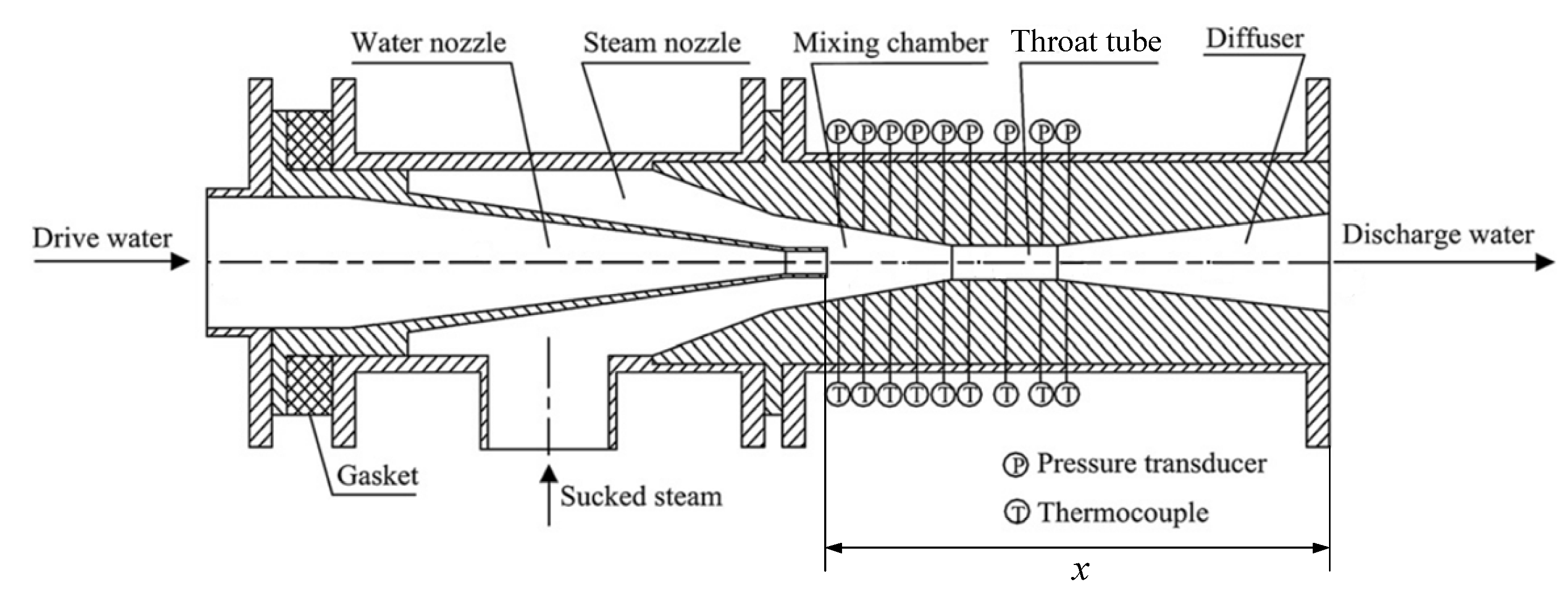
This study will focus on the steam–water injector with water as a primary stream flowing through the central water nozzle and steam as a second stream flowing through the steam nozzle, as shown in Figure 1. The injector consists of five parts: water nozzle, steam nozzle, mixing chamber, throat tube, and diffuser at the rear. The water and steam nozzles are both convergence nozzles. After acceleration in the water nozzle, the water enters the mixing chamber where it creates a low static pressure, which causes the steam to be drawn in through the steam nozzle. Due to the temperature and velocity difference between water and steam, heat, momentum and mass transfer can occur in the mixing chamber. As a result, the liquid phase is accelerated and heated up while the steam condenses and decelerate.

2.1. Modeling of Water Nozzle

In the water nozzle, if the inlet water pressure pw,0 and mass flow rate mw,0 are known, the pressure pw,2 at the water nozzle outlet can be calculated according to the Bernoulli equation between the inlet (section 0) and the outlet (section 2) of the water nozzle.
ρ w , 0 u w , 0 2 2 + ρ w , 0 g z 0 + p w , 0 = ρ w , 2 u w , 2 2 2 + ρ w , 2 g z 2 + p w , 2 + Δ p f + Δ p j
where uw,0, ρw,0, and pw,0 are the velocity, density, and pressure at section 0, respectively; uw,2, ρw,2, and pw,2 are the velocity, density, and pressure at section 2, respectively; Δpf is the frictional pressure drop; and Δpj is the local pressure drop. The frictional pressure drop Δpf can be obtained by:
Δ p f = f 1 ρ w , 0 u w , 0 2 2 L 1 d 1 + f 2 ρ w , 2 u w , 2 2 2 L 3 d 2
where L1 is the inlet straight section length of the water nozzle; L3 is the outlet straight section length of water nozzle; and f1 and f2 are the Darcy friction factors, which can be calculated using the Colebrook equation given in the literature [19].
The local pressure drop Δpj can be obtained by:
Δ p j = ζ 1 ρ w , 2 u w , 2 2 2
where ζ1 is the local loss coefficient, which can also be determined according to the dimensions of water nozzle, as indicated in Reference [19].

2.2. Modeling of the Steam Nozzle

As can be seen in Figure 1, the steam nozzle is a convergence nozzle from the inlet (section 1) to the outlet (section 2). Due to the short flow length of the steam nozzle, the steam condensation in the steam nozzle can be ignored. For a given inlet steam pressure ps,1 and temperature Ts,1, the inlet steam density ρs,1 can be calculated by IAPWS-IF97. It is assumed that the pressure at the outlet of water and steam nozzles is the same, ps,2 = pw,2. Therefore, the steam density at section 2 can be calculated by:
ρ s , 2 = ρ s , 1 p s , 2 p s , 1 1 n
where ρs,2 is the steam density at the outlet of steam nozzle. The value of n is 1.135 for a saturated steam condition and 1.3 for a superheated steam condition [20].
The steam velocity us,2 at the outlet of steam nozzle can be obtained by:
u s , 2 = 2 h s , 1 h s , 2
where hs,1 and hs,2 are the specific enthalpies of inlet steam and steam at section 2, respectively, which can also be obtained by IAPWS-IF97.
If the steam nozzle dimensions are known, the steam mass flow rate ms,2 can be calculated by:
m s , 2 = ρ s , 2 u s , 2 A s , 2
where As,2 is the area of the steam nozzle at section 2.
The entrainment ratio ϕ can be defined as:
ϕ = m s , 2 m w , 0

2.3. Modeling of Mixing Section

The water and steam flows through section 2 and come into contact in the mixing section. The mixing section consists of three parts, i.e., a mixing chamber, a throat tube, and a diffuser at the rear. A steam–water two-phase flow exists, and direct contact condensation between steam and water occurs in the mixing section. Therefore, the water mass flow rate increases and the steam mass flow rate decreases. Some researchers assumed that the steam completely condensed into water in the mixing section [9,15,21,22]; however, according to Abe and Shibayama [8], the steam flow did not condense completely in the mixing section, and the steam–water two-phase flow existed in the throat tube and the diffuser. Therefore, the flow model in the mixing section is mainly divided into two types: one is an upstream two-phase flow model and a downstream single-phase flow model, and the other is a two-phase flow model along the flow channel. Assuming that the steam flowrate is lower than a given minimum value, it can be considered that the steam is completely condensed. The flow model in the mixing section can be determined by judging whether the steam flowrate is less than the given value.

2.3.1. Steam–Water Two-Phase Flow Model

The mixing section is the most important part of the steam–water injector, where momentum (because of the velocity difference), mass (because of the related condensation) and heat (because of the temperature difference) transfers between two phases take place. Visualizations of flow structures in the centered water nozzle steam–water injector indicate the presence of an annular flow pattern in the mixing section [8]. The steam covers the wall all along the mixing section length with the water in the core of the flow. Moving towards the mixing section outlet, the steam condenses into the water. It is assumed that the steam is saturated at local pressure in the mixing section, and the water pressure pw,M is the same as the steam pressure ps,M, which is a well-known assumption in most two-phase flow configurations [15]. In this study, the parameters of steam and water in the mixing section are calculated by a stratified flow model.
Since the total mass flow rate in the centered water nozzle steam–water injector must be conserved, two equations are obtained as follows:
m w , M + m s , M = m M
d m w , M d x + d m s , M d x = 0
where the first subscripts w and s represent the water and the steam, respectively; the second subscript M represents the mixing section; mM is the total mass flow rate in the mixing section; mw,M is the water mass flow rate; and ms,M is the steam mass flow rate.
The mass conservation equation of steam can be given by:
1 A M d m s , M d x = Γ c
where AM is flow area in the mixing section and Γc is the condensation rate, which is determined according to Lee [23].
Γ c = λ c ρ s α s T s , M T w , M T s , M
where λc is the time relaxation parameter with a unit of s−1, and the value was suggested by Lee and Lyczkowski [24], Liu and Hao [25], and Wang et al. [26]; ρs is the density of steam, which can be calculated by the saturated state equation ρ = ρ(p); αs is the volume fraction of steam; and Ts,M and Tw,M are the steam temperature and water temperature, respectively.
For the momentum balance in the mixing section, two types of shear stresses must be taken into consideration, i.e., the wall shear stress τw and the steam–water interfacial shear stress τi. They are expressed as follows:
τ w = 1 2 f w ρ s u s , M 2
τ i = 1 2 f i ρ s u s , M u w , M 2
where us,M is the steam velocity; uw,M is the water velocity; and fw and fi are the wall friction factor and the interfacial friction factor, respectively, and values were suggested by Miwa et al. [7], Zhang et al. [9], and Chen et al. [27]. Then, the momentum equations for the steam flow and the water flow can be expressed as follows:
A s , M d p d x m s , M d u s , M d x = τ w + τ i β
A w , M d p d x m w , M d u w , M d x + u s , M u w , M d m w , M d x = τ i β
where β is the perimeter of the mixing section, As,M is the steam flow area, and Aw,M is the waterflow area.
Although the wall surface is adiabatic in the mixing section, the temperature of water flow is lower than that of steam flow, and there is heat exchange between the two-phase flow, accompanied by condensation. For the water flow, the energy conservation equation is as follows:
m w , M c p , w d T w , M d x + m w , M u w , M d u w , M d x + h s , M h w , M u w , M 2 2 d m w , M d x = u s , M u w , M τ i β
where cp,w is the water specific heat, hw,M is the water enthalpy, and hs,M is the steam enthalpy in the mixing section.
It is assumed that the steam in the mixing section is in a saturated state under the local pressure. Therefore, the steam temperature is always the saturation temperature, and its density is the saturated steam density. The values of steam temperature and steam density can be obtained according to IAPWS-IF97 below:
T s = T sat p
ρ s = ρ sat p
In addition, an equation needs to be added, as shown in Equation (19), in which the sum of the steam flow cross-section and water flow cross-section is equal to the mixing channel cross-section:
A s , M + A w , M = A M x
where AM is the mixing channel cross-sectional area, and its value varies along the flow direction x.

2.3.2. Single-Phase Flow Model

When the steam completely condenses into water in the mixing section, a homogeneous single-phase water flow exists in the rear channel, and the water pressure can be calculated according to the calculation method in Section 2.1.

2.4. Modeling of Shock Wave

The mixing chamber serves to create a homogeneous single- or two-phase fluid mixture which is ready to flow through the throat tube into the diffuser. If the fluid mixture entering the throat tube or the diffuser is in the supersonic flow regime, a shock wave may develop inside the throat tube or the diffuser.
The Mach number MaM of the two-phase fluid mixture can be defined as:
M a M = u M a M
where uM is the velocity of the two-phase fluid mixture, which can be calculated as:
u M = m w + m s ρ M A M
where AM is the fluid mixture flow area; mw and ms are the water and the steam flow rate of the two-phase fluid mixture, respectively; and ρM is the density of two-phase fluid mixture, which can be calculated as:
ρ M = 1 ν M
ν M = x M ν s + 1 x M ν w
where νM, νs, and νw are the specific volumes of two-phase fluid mixture, steam and water, respectively, and xM is the mass fraction of steam.
αM is the full equilibrium sound speed of the two-phase fluid mixture, which can be calculated according to Liu [28] as follows:
a M 2 = 1 ν M 2 ν M p s = 1 ν M 2 x M 1 R T 2 χ + T c p , s χ 2 ν s 2 + 1 x M T c p , w χ 2 ν s 2
where R is the gas constant, and χ is the latent heat. Following Deberne et al. [15], in order to obtain a normal shock wave, the upstream velocity uM must be higher than the full equilibrium sound speed αM.
As stated earlier, this two-phase mixture will undergo a velocity reduction accompanied by a pressure rise and will be subjected to a shock wave somewhere in the mixing section. In most cases, the fluid which is downstream of the shock wave is assumed to be only liquid. The thickness of the shock wave is sufficiently small to neglect the effect of the wall on the shock wave, and surface areas upstream and downstream of the shock wave are taken to be equal. The Mach number calculated above determines the latter issue and in case it is larger than 1, a shock wave is assumed to occur, and the following system of equations is assumed to apply.
Mass conservation equation:
ρ us u us = ρ ds u ds
where the subscripts us and ds represent the upstream fluid parameters and the downstream fluid parameters, respectively. The upstream fluid of the shock wave is in two-phase flow state, and its density is expressed by the homogeneous density value, which can be calculated as follows:
ρ us = α us ρ us , s + 1 α us ρ us , w
Momentum conservation equation:
ρ us u us 2 + p us = ρ ds u ds 2 + p ds
Energy conservation equation:
ρ ds u ds h ds + 1 2 u ds 2 = ρ us u us 2 2 + u us α us ρ us , s h us , s + 1 α us ρ us , w h us , w
where h is the specific enthalpy, which can also be obtained by IAPWS-IF97.

2.5. Solution of the Model

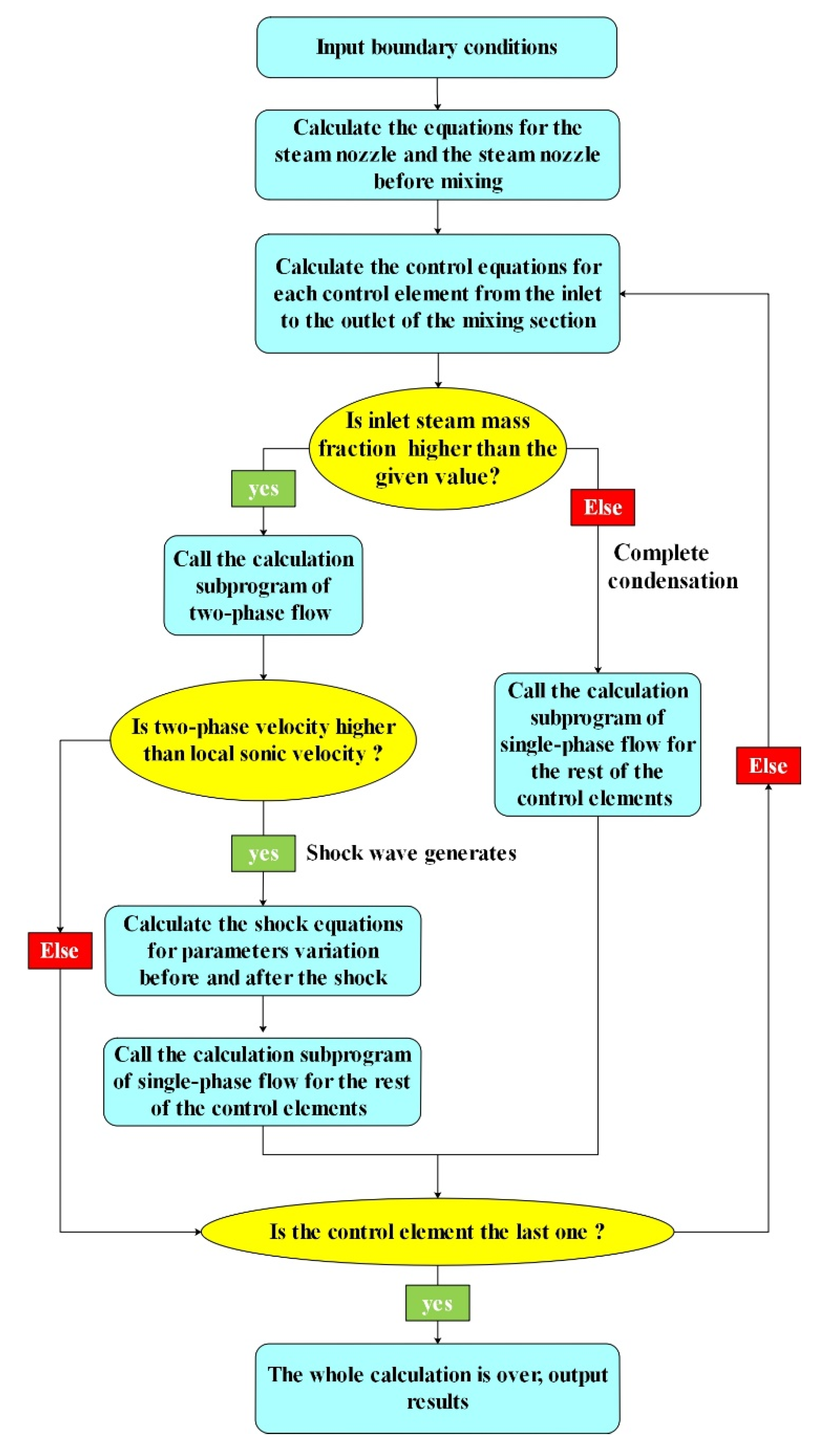
In this paper, the mixing section is divided into a series of grids (as shown in Figure 2), and the governing differential equations in the two-phase flow model and single-phase flow model in the mixing section are solved by the first-order explicit discrete scheme.
For any grid J, the discrete form of liquid phase momentum differential equation (Equation (14)) is expressed as follows:
A w , M j p j + 1 p j Δ x m w , M j u w , M j + 1 u w , M j Δ x + u s , M j u w , M j   m w , M j + 1 m w , M j Δ x = τ i j β j
The discrete form of other governing differential equations is similar to the above. To avoid repetition, it is not described in this study.
The solution process of the model in this paper is shown in Figure 3.

3. Model Validation and Discussion

The experimental data published by Zhao et al. [9] were utilized to validate the proposed numerical model. The parameters in the experiments from Zhao et al. [9] are depicted in Table 2.
The diagram of the test centered water nozzle steam–water injector is shown in Figure 4. In the experiments, the pressure and temperature are measured by the pressure transducer and the thermocouple, respectively.
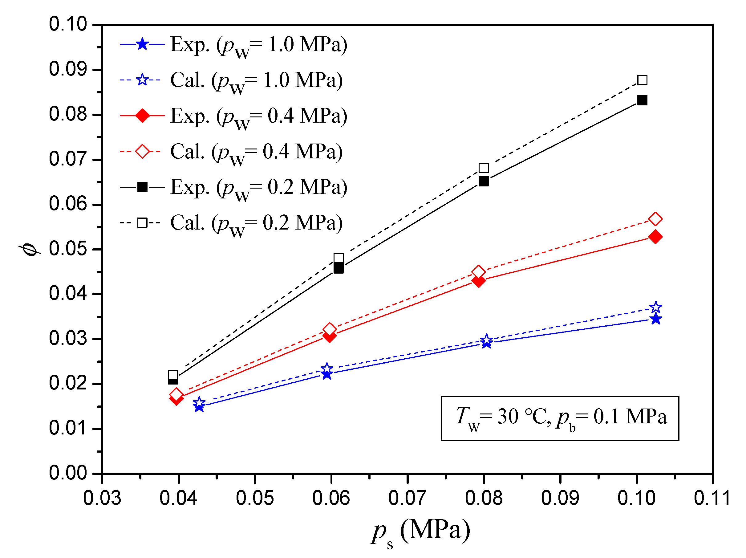
Figure 5 shows the comparisons between the calculated entrainment ratios and the experimental entrainment ratios for different inlet steam pressures. Compared with the experimental results, the maximum and the mean relative deviations of entrainment ratios are 5.5% and 4.9%, 7.6% and 5.4%, and 7.4% and 5.1%, respectively.
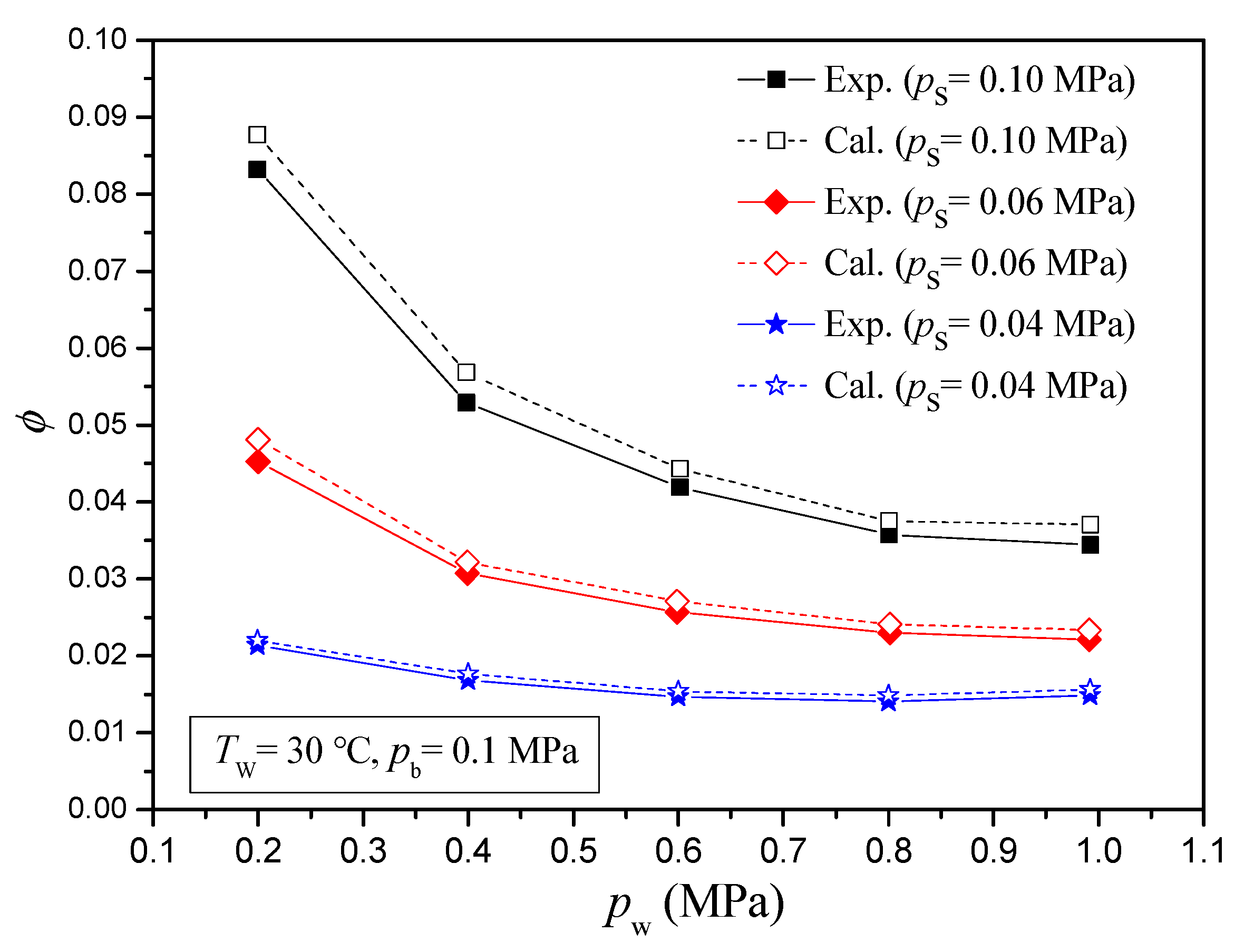
Figure 6 gives the entrainment ratio comparisons between the calculated results and the experimental results for different inlet water pressures. Compared with the experimental results, the maximum and the mean relative deviations of entrainment ratios are 7.7% and 6.3%, 6.3% and 5.4%, and 5.5% and 4.8%, respectively.
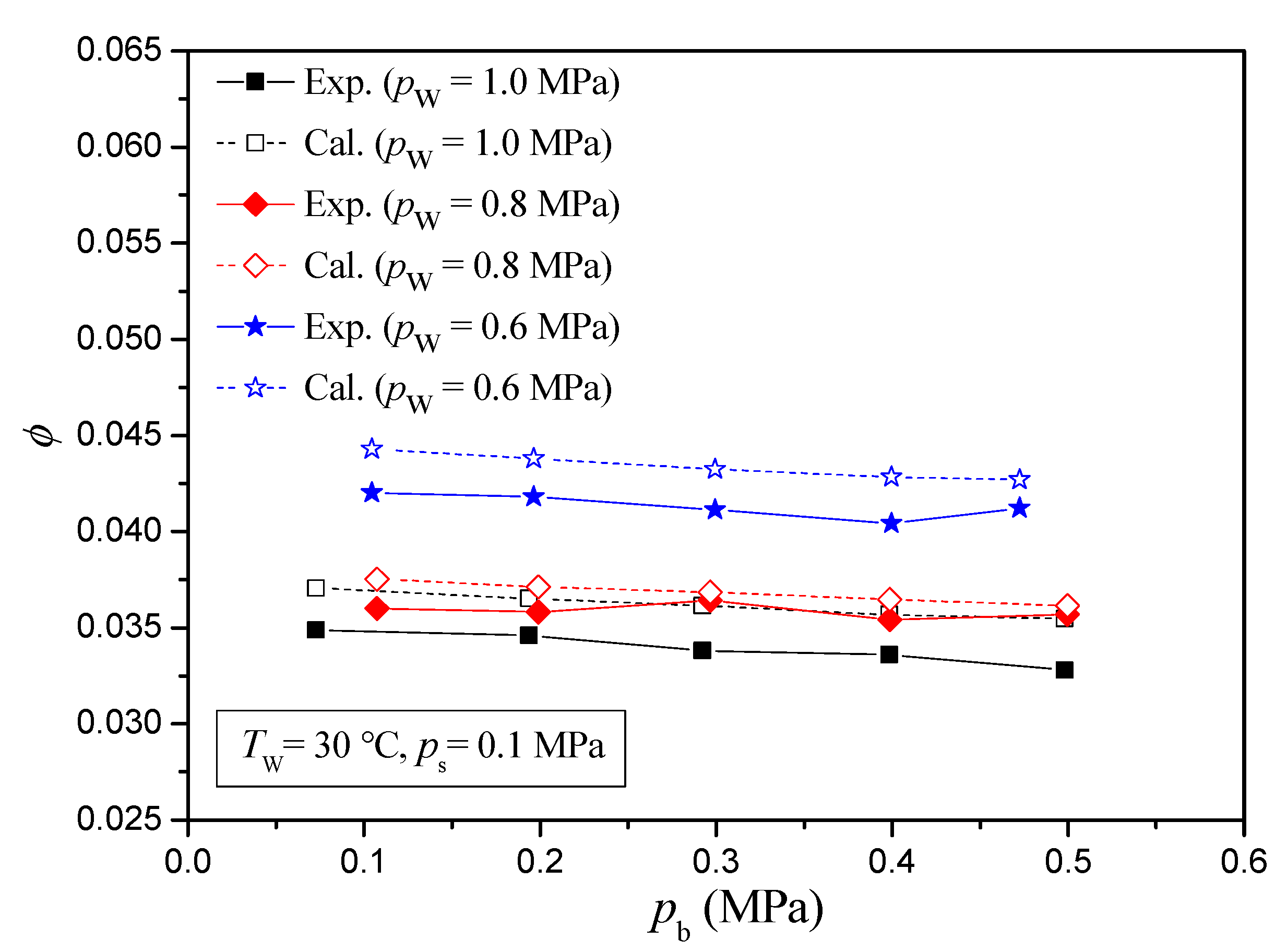
Figure 7 illustrates the entrainment ratio comparisons between the calculated results and the experimental results for different back pressures. Compared with the experimental results, the maximum and the mean relative deviations of entrainment ratios are 8.1% and 6.6%, 4.2% and 2.6%, and 5.9% and 5.0%, respectively. From the above comparisons under different inlet steam pressures, different inlet water pressures, and different back pressures, it is observed that the calculated results are in good agreement with the experimental results.
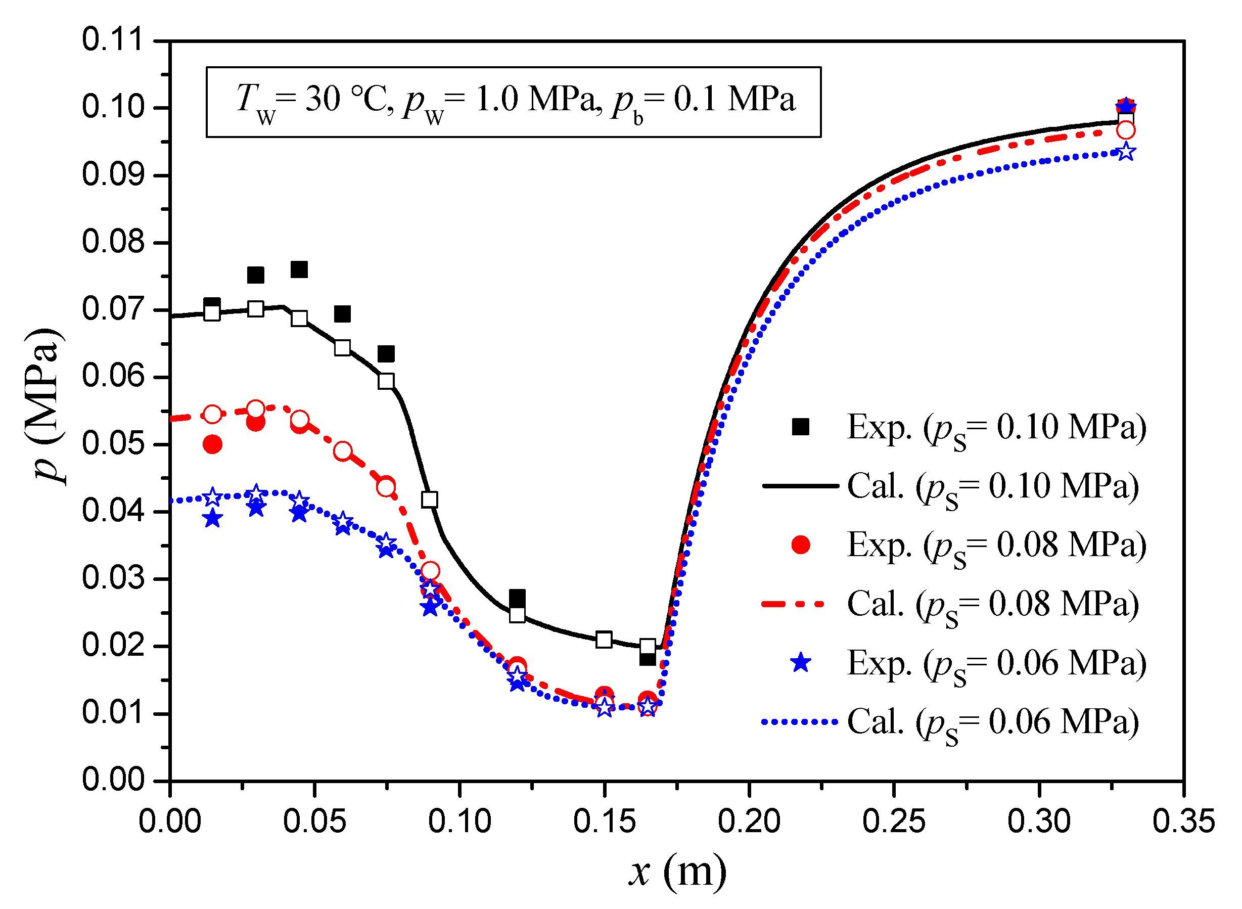
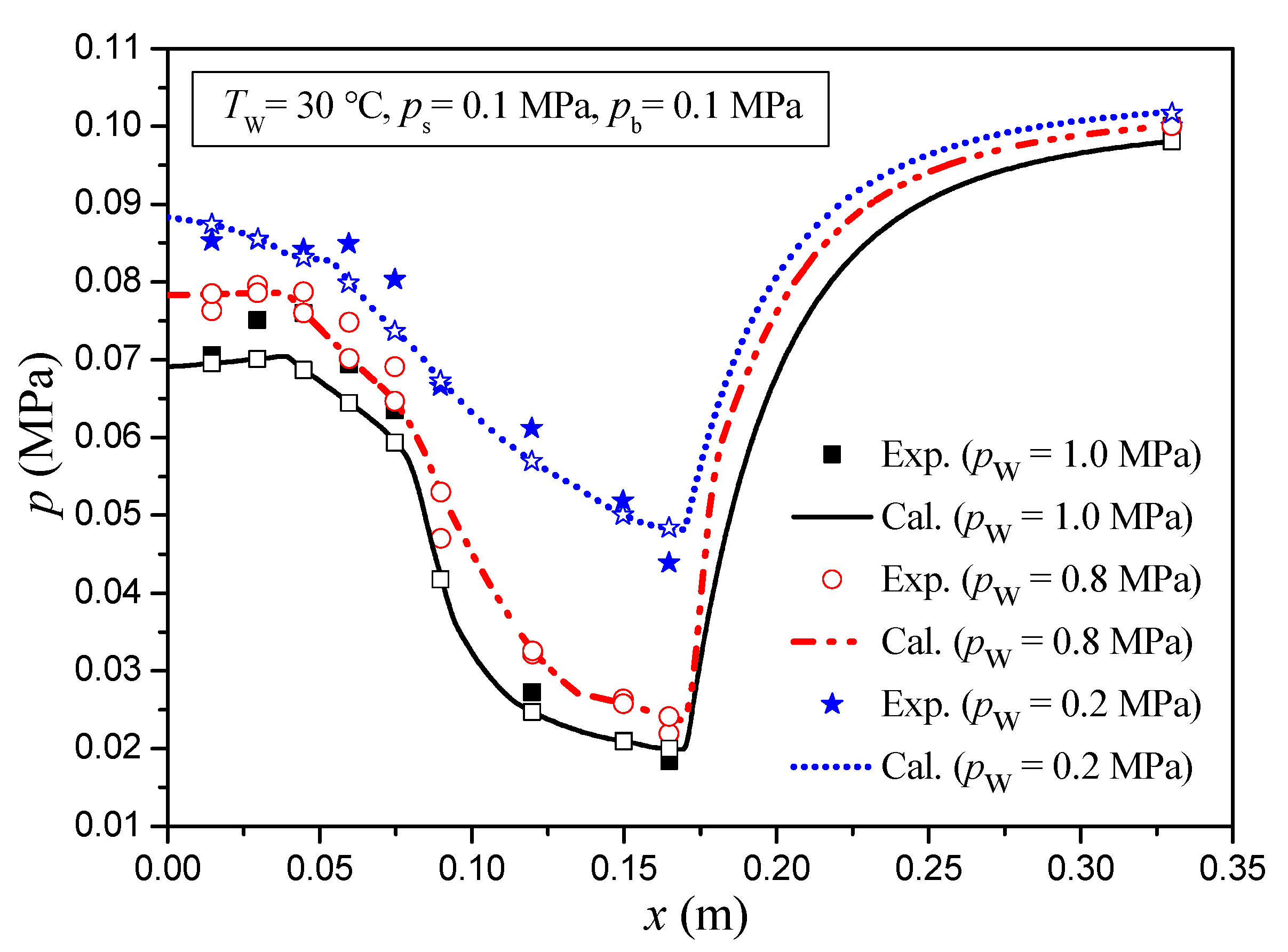
Figure 8 and Figure 9 show the pressure comparisons between the calculated results and the experimental results along the flow direction in the mixing section under pb = 0.1 MPa. As can be seen from Figure 8 and Figure 9, the pressure along the flow direction in the mixing section increases with the inlet steam pressure increasing, whereas it decreases with the inlet water pressure increasing. Compared with the experimental results, the maximum and the mean relative deviations of pressures along the flow direction in the mixing section under different inlet steam pressures are 9.6% and 3.5%, −9.9% and 1.0%, and 10.4% and −2.4%, respectively. The maximum and the mean relative deviations of pressures along the flow direction in the mixing section under different inlet water pressures are 9.6% and 3.5%, −10.4% and −0.4%, and −10.1% and 1.1%, respectively. According to Figure 8 and Figure 9, the calculated pressures agree well with the experimental pressures.
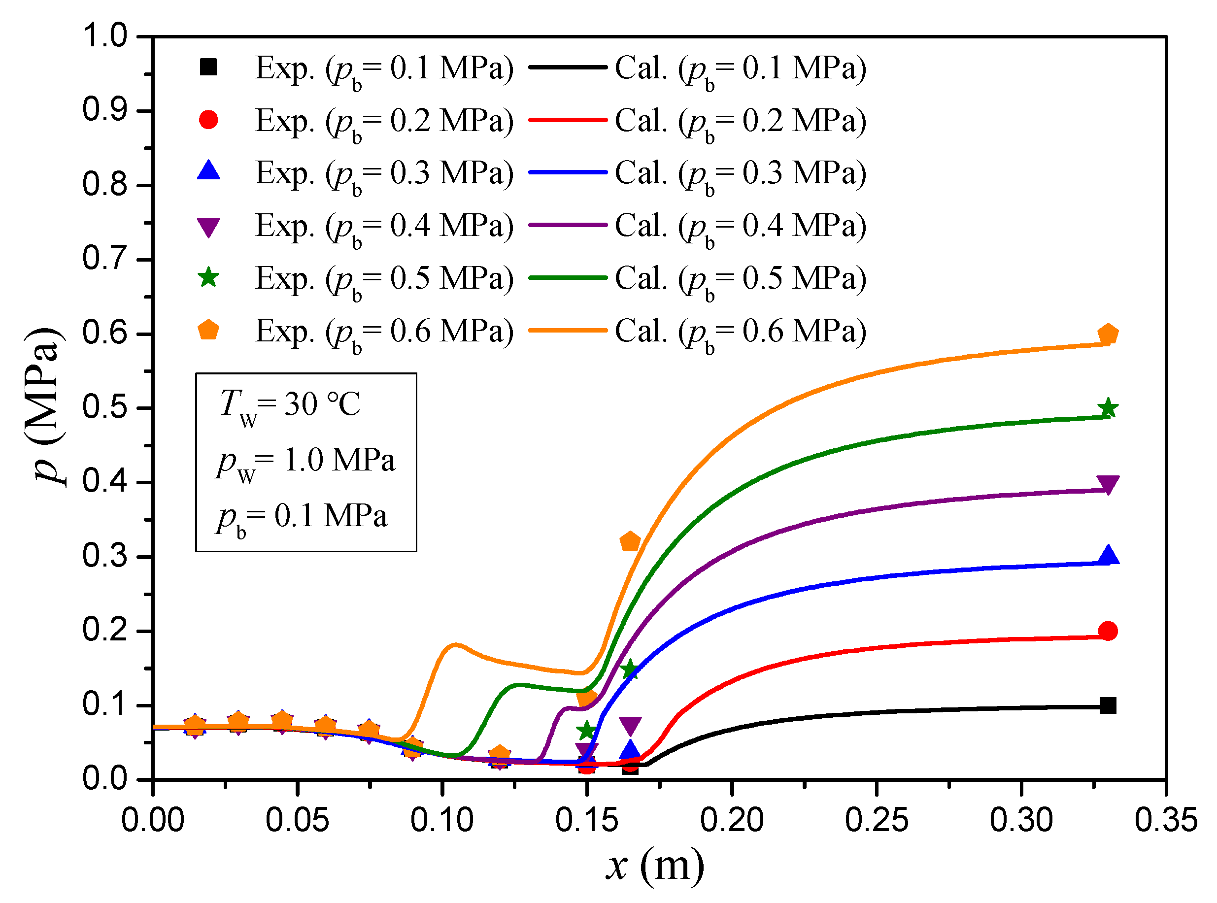
Figure 10 illustrates the comparisons of pressure along the flow direction in the mixing section between the calculated results and the experimental results under different back pressures. When the back pressure is small, no shock wave occurs in the mixing section, but with back pressure increasing, the pressure undergoes a dramatic increase in the throat tube, and the shock wave occurs. From Figure 10, it can be seen that the position of the shock wave moves towards the inlet of the mixing section. According to the calculated results, the model in this study is able to simulate the operating characteristics in the injector under different conditions.
From Figure 10, it can be seen that the calculated shock wave position is before the experimental shock wave position. As mentioned above, it is assumed that the shock wave only occurs when the upstream velocity uM is higher than the full equilibrium sound speed αM in this study. However, due to the complexity of shock wave characteristics, it is necessary to conduct a more in-depth study of shock wave characteristics in the mixing section to determine more detailed boundary conditions for the shock wave generation, which is also the focus of our future research.

4. Conclusions

In this study, a modified calculation method for a centered water nozzle steam–water injector is proposed and verified by experimental data in Reference [9]. The main conclusions can be summarized as follows:
(1)
The calculation method consists of a water nozzle model, a steam nozzle model, a mixing section model, and a shock wave model.
(2)
From the comparisons under different inlet steam pressures, different inlet water pressures, and different back pressures, it is known that the calculated results are in good agreement with the experimental results.
(3)
The model in this study can predict the operating characteristics in the injector under different conditions. When the back pressure is small, no shock wave occurs in the mixing section, but with the back pressure increasing, the pressure undergoes a dramatic increase in the throat tube, and the shock wave position moves towards the inlet of the mixing section. However, due to the complexity of shock wave characteristics, it is necessary to conduct a more in-depth study of shock wave characteristics in the mixing section to determine more detailed boundary conditions for the shock wave generation.

Author Contributions

Conceptualization, H.K. and L.T.; methodology, Q.X. and J.L.; software, J.L and L.T.; validation, H.K. and C.L.; formal analysis, H.K. and Q.X.; investigation, C.L.; resources, L.S.; data curation, L.S.; writing—original draft preparation, H.K. and Q.X.; writing-review and editing, C.L. and L.S.; visualization, L.S. and J.L.; supervision, L.T.; project administration, L.T.; funding acquisition, L.T. All authors have read and agreed to the published version of the manuscript.

Funding

This research was funded by the Open Fund of Science and Technology on Thermal Energy and Power Laboratory, grant number TPL2020B02; the Natural Science Basic Research Plan in Shaanxi Province of China, grant number 2021JQ-578; the Young Talent Fund of Association for Science and Technology in Shaanxi, China, grant number 20210404; and the Natural Science Basic Research Program of Shaanxi Province of China, grant number 2022JQ-542.

Conflicts of Interest

The authors declare no conflict of interest.

References

  1. Takeya, Y.; Miwa, S.; Hibiki, T.; Mori, M. Application of steam injector to improved safety of light water reactors. Prog. Nucl. Energy 2015, 78, 80–100. [Google Scholar] [CrossRef]
  2. Fukuichi, A.; Abe, Y.; Fujiwara, A.; Kawamoto, Y.; Iwaki, C.; Narabayashi, T.; Mori, M.; Ohmori, S. Study on turbulent behavior of water jet in supersonic steam injector. In Proceedings of the 16th International Conference on Nuclear Engineering, Orlando, FL, USA, 11–15 May 2008. [Google Scholar]
  3. Yan, J.; Chong, D.; Wu, X. Effect of swirling vanes on performance of steam-water jet injector. Appl. Therm. Eng. 2010, 30, 623–630. [Google Scholar] [CrossRef]
  4. Li, W.; Liu, M.; Yan, J.; Wang, J.; Chong, D. Exergy analysis of centered water nozzle steam-water injector. Exp. Therm. Fluid Sci. 2018, 94, 77–88. [Google Scholar] [CrossRef]
  5. Miwa, S.; Endo, H.; Moribe, T.; Sakashita, H.; Mori, M.; Hibiki, T. Investigation of the thermal-hydraulic characteristics of supersonic steam injector. Appl. Therm. Eng. 2016, 109, 261–271. [Google Scholar] [CrossRef]
  6. Miwa, S.; Endo, H.; Moribe, T.; Mori, M. Investigation of the supersonic steam injector operation mode. Nucl. Eng. Des. 2018, 334, 57–65. [Google Scholar] [CrossRef]
  7. Miwa, S.; Xu, Y.; Hibiki, T.; Sakashita, H.; Sawa, K. Pressure elevation of high-performance steam-water condensing-injector. Int. J. Heat Mass Transf. 2021, 170, 120971. [Google Scholar] [CrossRef]
  8. Abe, Y.; Shibayama, S. Study on the characteristics of the supersonic steam injector. Nucl. Eng. Des. 2014, 268, 191–202. [Google Scholar] [CrossRef]
  9. Zhang, Z.; Chong, D.; Yan, J. Modeling and experimental investigation on water-driven steam injector for waste heat recovery. Appl. Therm. Eng. 2012, 40, 189–197. [Google Scholar] [CrossRef]
  10. Yan, J.; Shao, S.; Liu, J.; Zhang, Z. Experiment and analysis on performance of steam-driven jet injector for district-heating system. Appl. Therm. Eng. 2005, 25, 1153–1167. [Google Scholar] [CrossRef]
  11. Trela, M.; Kwidzinski, R.; Butrymowicz, D.; Karwacki, J. Exergy analysis of two-phase steam-water injector. Appl. Therm. Eng. 2010, 30, 340–346. [Google Scholar] [CrossRef]
  12. Kwidzinski, R. Experimental investigation of condensation wave structure in steam-water injector. Int. J. Heat Mass Transf. 2015, 91, 594–601. [Google Scholar] [CrossRef]
  13. Kwidzinski, R. Experimental and theoretical investigations of two-phase flow in low pressure steam-water injector. Int. J. Heat Mass Transf. 2019, 144, 118618. [Google Scholar] [CrossRef]
  14. Kwidzinski, R. Condensation heat and mass transfer in steam-water injectors. Int. J. Heat Mass Transf. 2021, 164, 120582. [Google Scholar] [CrossRef]
  15. Deberne, N.; Leone, J.F.; Duque, A.; Lallemand, A. A model for calculation of steam injector performance. Int. J. Multiphase Flow 1999, 25, 841–855. [Google Scholar] [CrossRef]
  16. Xu, Q.; Liang, L.; She, Y.; Xie, X.; Guo, L. Numerical investigation on thermal hydraulic characteristics of steam jet condensation in subcooled water flow in pipes. Int. J. Heat Mass Transf. 2022, 184, 122277. [Google Scholar] [CrossRef]
  17. Xu, Q.; Liu, C.; Liu, Q.; Zhu, Y.; Zhou, H.; Guo, L. Interfacial characteristics of steam jet condensation in subcooled water pipe flow—An experimental and numerical study. Chem. Eng. Sci. 2022, 251, 117457. [Google Scholar] [CrossRef]
  18. Zhao, Q.; Fu, P.; Chong, D.; Chen, W.; Liu, J.; Yan, J. Steam entrainment and heat transfer characteristic of steam submerged jet condensation within steam-water mixture layer. Int. J. Heat Mass Transf. 2023, 201, 123600. [Google Scholar] [CrossRef]
  19. Munson, B.R.; Youn, D.F.; Okiishi, T.H. Fundamentals of Fluid Mechanics, 4th ed.; John Wiley & Sons Inc.: New York, NY, USA, 2002. [Google Scholar]
  20. Reisel, J.R. Principles of Engineering Thermodynamics, 1st ed.; Cengage Learning: Stamford, CT, USA, 2015. [Google Scholar]
  21. Beithou, N.; Aybar, H.S. A mathematical model for steam-driven jet pump. Int. J. Multiph. Flow 2000, 26, 1609–1619. [Google Scholar] [CrossRef]
  22. Ma, H.; Zhao, H.; Wang, L.; Yu, Z.; Mao, X. Modeling and investigation of a steam-water injector. Energ. Convers. Manage. 2017, 151, 170–178. [Google Scholar] [CrossRef] [Green Version]
  23. Lee, W.H. A pressure iteration scheme for two-phase flow modeling. In Multiphase Transport Fundamentals, Reactor Safety, Applications; Veziroglu, T.N., Ed.; Hemisphere Publishing: Washington, DC, USA, 1980; Volume 1. [Google Scholar]
  24. Lee, W.H.; Lyczkowski, R.W. The basic character of five two-phase flow model equation sets. Int. J. Numer. Meth. Fluids 2000, 33, 1075–1098. [Google Scholar] [CrossRef]
  25. Liu, X.; Hao, Y. Numerical simulation of vapor-liquid two-phase flow in a closed loop oscillating heat pipe. In Proceedings of the ASME International Mechanical Engineering Congress & Exposition, Lake Buena Vista, FL, USA, 13–19 November 2009. [Google Scholar]
  26. Wang, J.; Ma, H.; Zhu, Q.; Dong, Y.; Yue, K. Numerical and experimental investigation of pulsating heat pipes with corrugated configuration. Appl. Therm. Eng. 2016, 102, 158–166. [Google Scholar] [CrossRef]
  27. Chen, J.; Huang, Y.; Niu, Z.; Chen, Y.; Luo, X. Performance analysis of a novel organic Rankine cycle with a vapor-liquid ejector. Energ. Convers. Manage. 2018, 157, 382–395. [Google Scholar] [CrossRef]
  28. Liu, D. The speed of sound in two-phase flows under the condition of velocity-equilibrium between phases. Acta Mech. Sin. 1999, 22, 660–669. (In Chinese) [Google Scholar]
Figure 1. Schematic of the centered water nozzle steam–water injector.
Energies 15 09159 g001
Figure 2. Schematic of grids in the mixing section.
Energies 15 09159 g002
Figure 3. Solution process of the model.
Energies 15 09159 g003
Figure 4. Schematic of the test centered water nozzle steam–water injector.
Energies 15 09159 g004
Figure 5. ϕ comparisons for different inlet steam pressures.
Energies 15 09159 g005
Figure 6. ϕ comparisons for different inlet water pressures.
Energies 15 09159 g006
Figure 7. ϕ comparisons for different back pressures.
Energies 15 09159 g007
Figure 8. Pressure comparisons for different inlet steam pressures.
Energies 15 09159 g008
Figure 9. Pressure comparisons for different inlet water pressures.
Energies 15 09159 g009
Figure 10. Pressure comparisons for different back pressures.
Energies 15 09159 g010
Table 1. Calculation method in existing literatures and this study.
ReferencesInjectorModelCalculation Results
Zhang et al. [9]Centered water nozzle steam–water injectorThe calculation method consisted of water nozzle model, steam nozzle model, mixing chamber model, throat tube model, and diffuser model, but no shock wave model. It was assumed that steam completely condensed into water in the mixing chamber and throat tube, and only the water existed in the diffuser.The shock wave characteristics were not reflected in the calculation results, and the pressure distribution along the flow direction in the diffuser was not calculated.
Yan et al. [10]Centered steam nozzle steam–water injectorThe calculation method consisted of water nozzle model, steam nozzle model, mixing chamber model, and diffuser model, but shock wave model was not considered. It was assumed that steam completely condensed into water at the end section of the mixing chamber, and only the water existed in the diffuser.An empirical equation to calculate the outlet water pressure of the water nozzle was given according to the experimental results, and the performance parameters of the injector were not calculated.
Kwidzinski [13]Centered steam nozzle steam–water injectorA model consisting of a water nozzle, steam nozzle, mixing chamber, condensation wave, and diffuser was considered. It was assumed that steam completely condensed into water in the mixing chamber, and only the water existed in the diffuser.Based on his calculation method, the pressure along the flow direction in the diffuser was calculated according to the Bernoulli equation.
Deberne et al. [15]Centered steam nozzle steam–water injectorA model consisting of a water nozzle, steam nozzle, mixing chamber, shock wave, and diffuser was considered. It was assumed that steam completely condensed into water in the mixing chamber, and only the water existed in the diffuser.The shock wave characteristics were experimentally measured but not calculated, and the calculated pressure along the flow direction in the injector was not given.
This studyCentered water nozzle steam–water injectorA model consisting of a water nozzle, steam nozzle, mixing chamber, shock wave, and diffuser is considered. Steam may not completely condense into water in the mixing chamber or throat tube, so the continuous condensation of steam in the diffuser must be considered.Steam continues to condense into water in the diffuser based on the calculation method under a certain operating condition, and the calculated results show that the calculation method can predict the shock wave characteristics.
Table 2. Parameters of steam inlet, water inlet and injector configuration.
ParametersSymbol/UnitValues
Inlet water pressurepw/MPa0.1–1.0
Inlet water temperatureTw/°C25–70
Inlet steam pressureps/MPa0.02–0.1
Inlet steam temperatureTs/°C95–120
Water nozzle inlet diameterd1/mm80
Water nozzle outlet diameterd2/mm14
Water nozzle inlet straight lengthL1/mm80
Water nozzle convergence lengthL2/mm267
Water nozzle outlet straight lengthL3/mm33
Steam nozzle inlet diameterd5/mm113
Mixing chamber convergence lengthL4/mm85
Throat tube diameterd3/mm21
Throat tube lengthL5/mm70
Diffuser outlet diameterd4/mm60
Diffuser divergence lengthL6/mm180
Publisher’s Note: MDPI stays neutral with regard to jurisdictional claims in published maps and institutional affiliations.