Abstract
Aiming at the problem of maximum power point tracking (MPPT) of photovoltaic arrays in photovoltaic power generation systems, a particle swarm optimization (PSO) MPPT method combined with adaptive linear active disturbance rejection control (A-LADRC) algorithm was proposed and designed. In this method, PSO is used to track the maximum power point (MPP), and then the A-LADRC controller was used to track the reference voltage. The controller enhances the anti-interference ability against various external disturbances in the MPPT process and accelerates the response speed of the system. Compared with the perturbation observation method (P&O), traditional PSO and LADRC, the proposed method has good tracking performance and an anti-interference ability under various external disturbances.
1. Introduction
With the occurrence of the first industrial revolution, productivity and industrialization levels have been continuously improved, and a large amount of energy has been produced. The excessive use of traditional fossil energy causes environmental pollution. However, because traditional energy cannot be recovered and regenerated, this leads to energy depletion, which seriously hinders the further development of society. At present, coal and other traditional energies still account for a large proportion of the energy structure. In terms of power resource consumption, the growth rate of the power demand has been relatively high in recent years. Sustainable development faces the dual challenges of energy and the environment [1,2,3]. Solar energy is widely used in the development of the power industry due to its clean and long-term characteristics [4,5]. As a key part of solar power generation, the output characteristic curve of the photovoltaic array is nonlinear due to the influence of light, temperature, etc. [6]. In order to maximize the power generation efficiency of photovoltaic arrays, MPPT technology is introduced in practical engineering applications. Therefore, it is very meaningful to put forward an appropriate MPPT control method [7].
Ref. [8] introduced several MPPT methods and implemented them in a MATLAB/Simulink environment. The above methods such as P&O and artificial neural network (ANN) can effectively solve the problem of maximum power point tracking. Ref. [9] proposed an MPPT algorithm based on system identification (SI) for PV systems under partial shading (PS) conditions. This method does not require the measurement of PV panel currents. The MPPT algorithm is developed for the motors with nonlinear pump loads. Ref. [10] proposed an enhanced P&O algorithm and a check algorithm. In the local shadow, MPPT is achieved by comparing all the peaks on the PV curve. The algorithm improves the tracking efficiency of traditional P&O MPPT by more than 16% under partial shadow. Ref. [11] proposed a new model-based MPPT method for local shading of photovoltaic arrays. This method estimates the MPP of each PV series, and by solving the nonlinear equation of the PV series numerically, the output current and power of the PV array corresponding to the MPP voltage of each PV series are calculated, so as to achieve MPPT. Ref. [12] proposed an MPPT technique based on load voltage (LVB), which adopts adaptive step size (ASS) for independent photovoltaic systems. The technique uses adaptive control to adjust the step size, thus improving the convergence speed of MPPT. Ref. [13] proposed an MPPT control strategy with an improved bacteria foraging algorithm. This method enhances the global optimization capability of the algorithm by improving the compensation and migration probability of bacteria swimming. Ref. [14] proposed the improved PSO algorithm and the MPPT algorithm combined with the neural network and disturbance observation methods, respectively. In this paper, the application of these two MPPT algorithms in different external conditions is simulated, which shows the advantages of these two methods. Ref. [15] proposed an MPPT control scheme based on the horse racing algorithm, which optimized the MPPT process according to the rules of horse racing. The simulation results show that this method reduces the transient oscillation in the MPPT process, avoids it falling into the local optimal situation in the optimization process and can rapidly achieve target tracking. Ref. [16] proposed an MPPT control method based on the marine predator algorithm. This algorithm is an algorithm that imitates the predation law of marine organisms. The experimental results show that this method can achieve good tracking abilities in the face of different external conditions. Ref. [17] proposed an improved incremental conductance MPPT algorithm with a variable step size. Compared with the traditional incremental conductance method, this alternative adjusts the step size to speed up the optimization of the MPPT process, and also improve the optimization accuracy. However, this method cannot solve the multi-peak problem of the P-V output characteristic curve of photovoltaic arrays under local shadows. Ref. [18] proposed an MPPT control technology based on the Grey Wolf Optimization (GWO) algorithm, which improved the tracking efficiency in the MPPT process and reduced problems such as steady-state oscillation. In addition to adopting an appropriate control algorithm to track MPP, MPPT also needs to consider control voltage and current, so a voltage-oriented method (vo-MPPT) and a current-oriented method (co-MPPT) are applied to MPPT. Ref. [19] proposed a new MPPT method using the sliding mode control. This method uses the P&O method to track the MPP and output the working voltage of the photovoltaic array at this time as the reference value, and SMC is used to improve the current inner loop controller. This method can track the MPP rapidly and effectively and restrain the influence of the grid side on the photovoltaic array. Ref. [20] applied the final-state predictive control and valley current control to the current- or voltage-oriented MPPT. The experimental results show that this method has the advantages of fast response speed and high tracking accuracy in the application of vo-MPPT. However, co-MPPT cannot effectively handle the interference caused by the change of external environment. Ref. [21] proposed an MPPT method based on fixed step size prediction. Based on co-MPPT, the controller is improved by model prediction technology. This method can effectively solve the MPPT problem under the condition of light intensity variation and shadow. Ref. [22] applied predictive control to the control of large-scale photovoltaic grid-connected systems. This method applies vo-MPPT to boost converters and optimizes the inner loop controller by predictive control, which provides high performance tracking of power oscillations. According to the reference [19,20,21,22], the implementation of co-MPPT is relatively simple and responsive, but it cannot effectively address the situation when the light intensity drops suddenly. Vo-MPPT control can effectively address the influence of step change of light intensity. Considering the vo-MPPT method, a PSO-based MPPT method is proposed in this paper, and an A-LADRC controller is designed to improve it. Meanwhile, LADRC technology has been increasingly applied to other kinds of domains with its good anti-interference ability, fast response speed and other advantages. In [23], the LADRC controller was applied to the control scheme of a high-speed train, so that the train can achieve speed tracking control accurately and rapidly, and the impact caused by external interference is suppressed. In [24], in order to keep the DC bus voltage of the inverter stable during operation, LADRC is applied to the inverter control strategy to complete the control of the inverter bridge. This method enhances the response speed of the system and effectively responds to the interference caused by changes in external conditions. In [25], LADRC is applied to solve the issue of accurate path tracking planning for high-speed parallel robots. In order to overcome the issue of coupling in the system, the state observer is used to observe and compensate for the internal coupling and interference of the robot. Finally, the comparison with other algorithms shows that the application of an LADRC controller improves the steady and transient performance of the robot system. Ref. [26] applies LADRC to hybrid electric vehicles. It shows that the output speed curve of the motor under the control of LADRC can rapidly track the reference curve. In addition, LADRC is also used in various other engineering areas due to its wide adaptability [27,28,29].
In order to make the MPPT process of photovoltaic cells under local shadow respond faster and have a stronger anti-interference ability, this paper proposes an MPPT controller combined with an A-LADRC controller. The control method is based on the PSO algorithm and optimized by the A-LADRC controller. The application of adaptive control (APC) simplifies the process of parameter adjustment, and the parameters of the controller change in a timely manner according to the changes in external conditions and tend to be optimal, which improves the control performance. The composition of this paper is as follows:
- (1)
- According to the schematic diagram of photovoltaic cells and related mathematical equations, the mathematical model of photovoltaic cell engineering is established and simplified. The PV array is obtained through series and parallel connection of PV cells, and the mathematical model of the combination of PV array and Boost is further obtained.
- (2)
- This paper proposes an MPPT technology combining PSO with A–LADRC. In practical projects, the MPPT process of photovoltaic array output will be affected by changes in external lighting conditions and temperature. Therefore, on the basis of the MPPT control strategy using the PSO algorithm, the LADRC controller is used to enhance the response speed and anti-interference ability of the tracking process. APC is introduced into the LADRC controller for parameter adjustment. This method simplifies the parameter adjustment process and optimizes the control performance when it faces complex and changeable external conditions.
- (3)
- The uniform stability of the system is proved by the Lyapunov theory, and the uniform asymptotic stability of the system is further proved by the Barbalat theorem. The comparative analysis shows that the scheme can restrain the disturbance caused by external changes, and the response time is short in the case of sudden changes in light and temperature.
The composition of this paper is as follows: in Section 2, the mathematical models of photovoltaic cells and photovoltaic arrays are established; Section 3 designs the MPPT control scheme; stability analysis is carried out in Section 4; Section 5 analyzes the experimental results; Section 6 summarizes the contents of the full text and puts forward the unresolved problems.
2. Modeling of Photovoltaic System
2.1. Mathematical Model of Photovoltaic Cell
The output characteristic curve of photovoltaic cells is determined by internal parameters and external conditions (light intensity, temperature) [30]. Assuming that the photovoltaic cell is under standard test conditions (temperature T is 25 °C, and light intensity S is 1000 W/m2), when the photovoltaic cell is working in MPP, the corresponding voltage value is and current value , and represent the short circuit current and open circuit voltage of photovoltaic cells, respectively. Then, the mathematical model of the photovoltaic cell is established, as shown in Formulas (1) and (3).
where is the output current under the current working condition, and are the undetermined coefficients under the current working condition, is the open circuit voltage under the current working condition, is the short circuit current under the current working condition, is the voltage at MPP and is the current at MPP. These formulas are as follows:
where is light intensity and is temperature. The light intensity and temperature under the standard state are and , respectively. When the photovoltaic cell type used is monocrystalline silicon, the coefficient value, in the above expression, of α is usually 0.0025/°C, the coefficient b value is usually 0.5 and the coefficient c value is usually 0.00228/°C. The selection of these three values is typical [31,32,33].
2.2. MPPT Modeling of Photovoltaic System
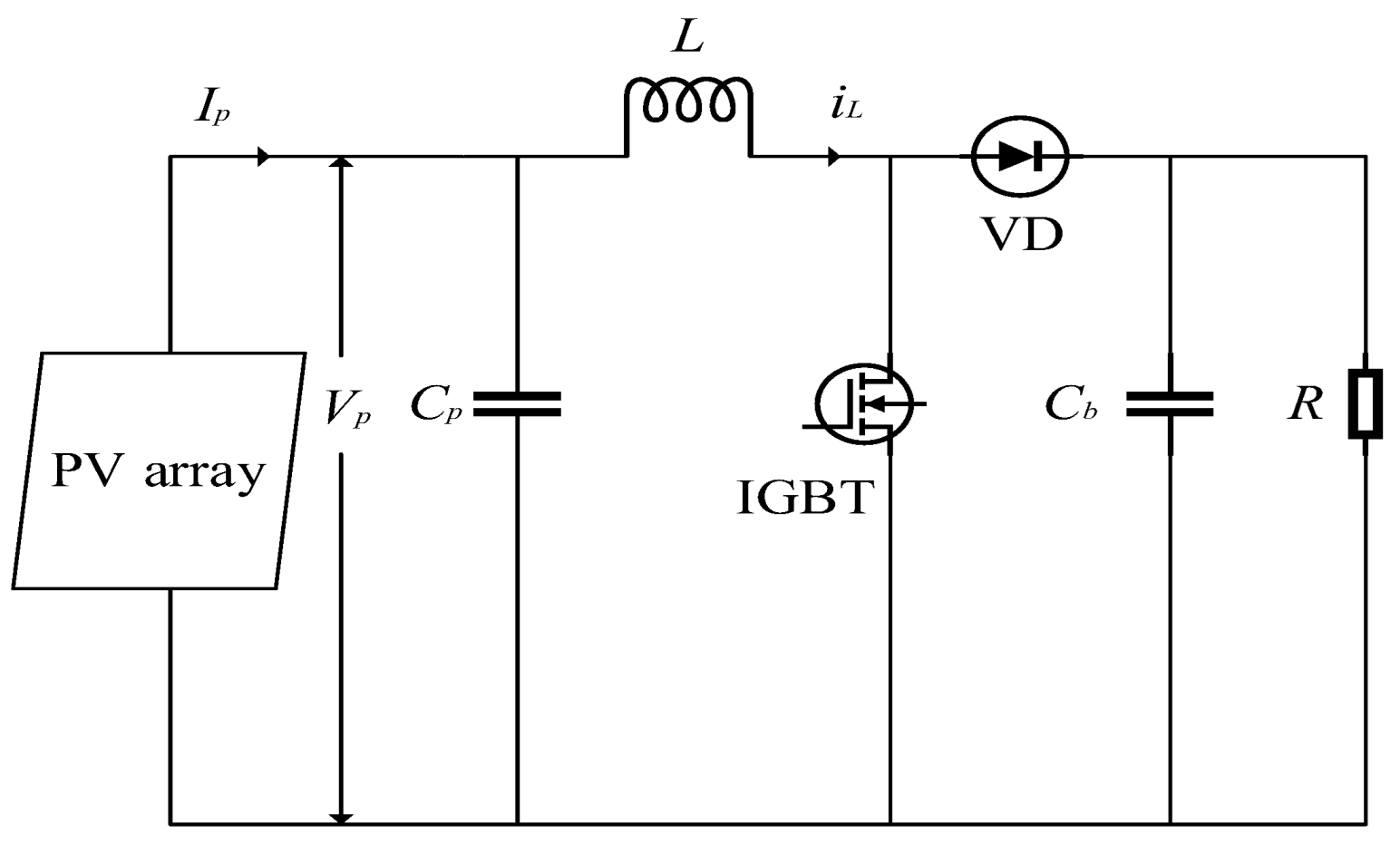
In this paper, the PV power generation system uses the Boost circuit to achieve the MPPT process. At this time, the equivalent circuit of the PV power generation system is shown in the Figure 1:
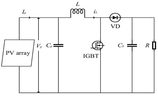
Figure 1.
Equivalent circuit of photovoltaic power generation system.
The system average method [34] is used for modeling. According to Kirchhoff laws, the following can be obtained:
where
where is the output of the system, is the input of the system, is the output voltage of photovoltaic cell, is the output current of photovoltaic cell, is inductive current, is the load voltage, is the duty cycle, is the inductance value, is the resistance value and , are the capacitance values.
Taking the strong coupling relationship between state variables as the internal disturbance of the system [35], Formula (11) can be further deduced as:
Among this are the external disturbances of the system, such as the uncertainty of Boost converter parameters, switching losses, system estimation, and measurement errors, etc. Therefore, Formula (12) can be written as:
where is the total disturbance and is the disturbance factor.
Remark 1.
It shows from formula (11) that the photovoltaic power generation system is a nonlinear system with strong coupling relationships. Therefore, in the process of system design, this paper defines the strong coupling relationships between various state variables, the nonlinear part in system modeling, external disturbances and other uncertainties as the total disturbance of the system, and observes and compensates for the total disturbance through the LESO in LADRC. Meanwhile, LESO can also naturally decouple the nonlinear strong coupling part of the system modeling, such as duty cycle d, thus simplifying the design of the controller.
3. Design of MPPT Controller
3.1. Design of MPPT Control System
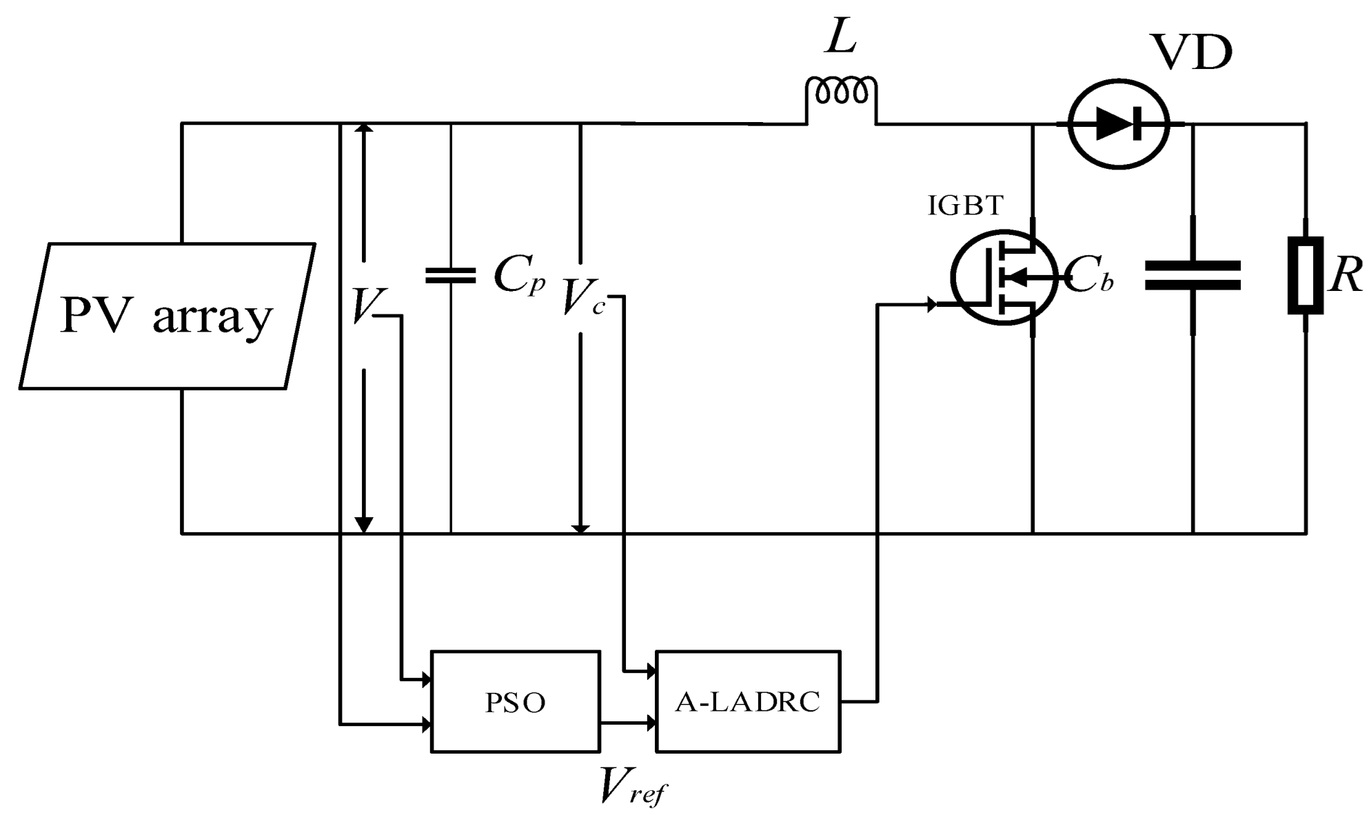
In the MPPT design of this paper, the PSO algorithm is used to solve the multi-peak problem of P-V output curve under the condition of local shadow of photovoltaic array, which avoids the problem that the traditional MPPT control methods are prone to fall into, namely local optimization and the inability to trace MPP. However, the PSO algorithm still has some problems, such as slow response speed and poor anti-interference ability. Since a controller is needed to track the voltage reference value generated by an MPPT unit, the A–LADRC controller is proposed and applied. The introduction of LADRC enhances the anti-interference ability of the system and accelerates the speed of MPP tracking. APC is used to adjust the parameters in LADRC. This method simplifies the process of parameter adjustment and solves the problem that the control performance of the LADRC controller declines when the external conditions change due to parameter solidification. The basic idea of the MPPT control strategy is that the PSO algorithm performs optimization and outputs the working voltage at the MPP as the reference voltage. The A-LADRC controller adjusts the error signal of the reference voltage and the actual working voltage to output the PWM signal, and then adjusts the switching device through the obtained PWM signal to complete the tracking of the MPP. Figure 2 shows the structure diagram of the designed control scheme.
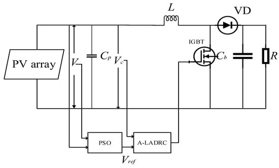
Figure 2.
Structure of MPPT control scheme.
3.2. Design of PSO
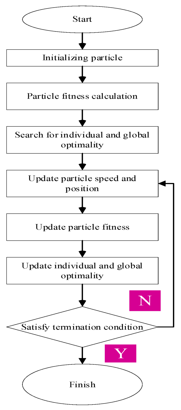
As an intelligent algorithm, PSO is widely used in various optimization problems [36]. In PSO, there are i particles randomly distributed in the D dimension search space, of which represent a solution of the optimization problem in the D dimension space, corresponding to the position of the ith particle in the particle swarm; represent the optimal position on all the paths experienced by the ith particle, that is, the local optimal solution searched; represent the optimal position on the path that all particles have experienced, that is, the global optimal solution; indicates the velocity of the particle. Formulas (14) and (15) are the core formulas in the PSO, and particles update their positions and velocities through these two formulas.
where i = 1, 2, 3, …, m represent the particle number; k is the number of iterations; w is the inertia weight; c1, c2 are learning factors; r1, r2 are independent random numbers with values of 0–1 to increase the randomness of the search. The flow chart of the PSO is shown in Figure 3.
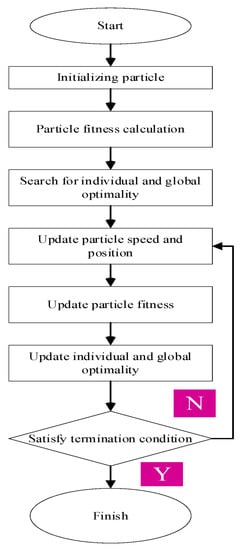
Figure 3.
Flow chart of PSO algorithm.
3.3. A-LADRC Controller Design
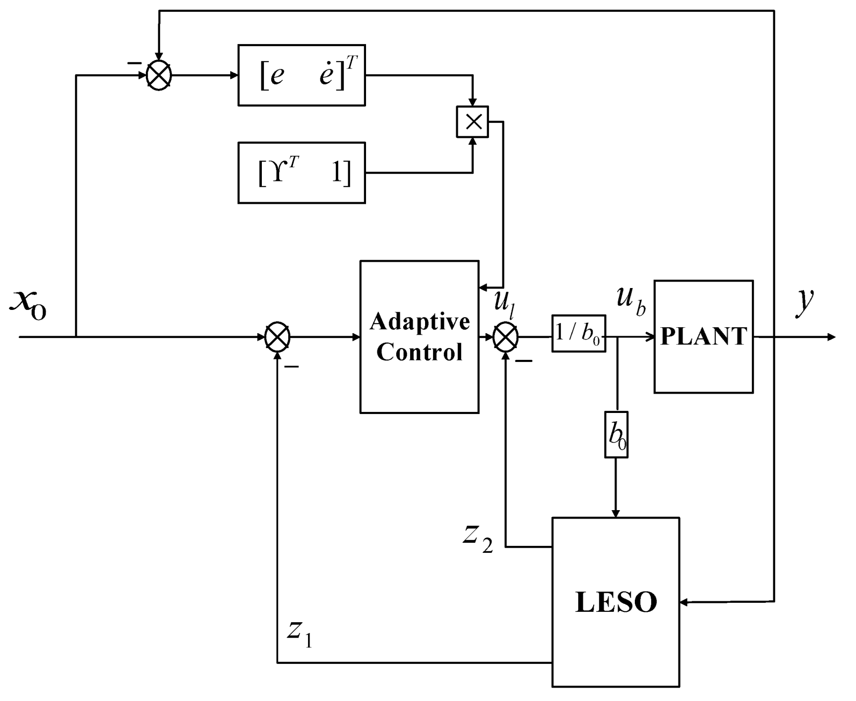
LADRC consists of linear extended observer (LESO), tracking differentiator (TD) and linear error state feedback (LESF) control law [37,38]. The structure of the A-LADRC controller is shown in Figure 4. LESO observes the total disturbance of the system through the input signal and output signal of the controlled object and compensates it through LESF. The tracking error is defined according to the difference between the output signal of the system and the expected signal , and an adaptive law is designed according to the tracking error. The parameter in the LESF is adjusted through adaptive control.
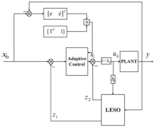
Figure 4.
Structure of first-order LADRC controller.
According to formula (13), the system is a first-order system, so first-order LADRC is used to control it. The model is expanded to:
where ; therefore, the second-order LESO can be designed as:
where and are observer gains. By select the appropriate parameters and , it enables LESO to achieve real-time tracking of photovoltaic cell output voltage and total disturbance. The gain of the linear state observer is parameterized by placing all eigenvalues in the observation bandwidth. Among them, the gain of the state observer can be obtained through its characteristic formula:
where , is the bandwidth of LESO.
Remark 2.
LESO does not need an exact model, and its establishment depends on the order of the controlled object [39]. A photovoltaic power generation system is a first-order system, so a second-order LESO is designed in this paper. It can regard the influence of disturbance on the system as extended state, observe the output of the system and then compensate for the extended state feedback of the system output through the controller.
The LESF is designed as:
Therefore, the input control rate of the controlled object can be obtained:
Remark 3.
The control effect of the traditional first-order LADRC controller is affected by the value of the parameter, but when the external conditions change, the traditional LADRC parameters are generally laborious to determine and to set the most appropriate value. The introduction of APC effectively solves the error problem caused by unsuitable parameters in the process of LADRC parameter setting, as well as simplifies the parameter adjustment process. Meanwhile, it provides a new method for the stability analysis of the whole system.
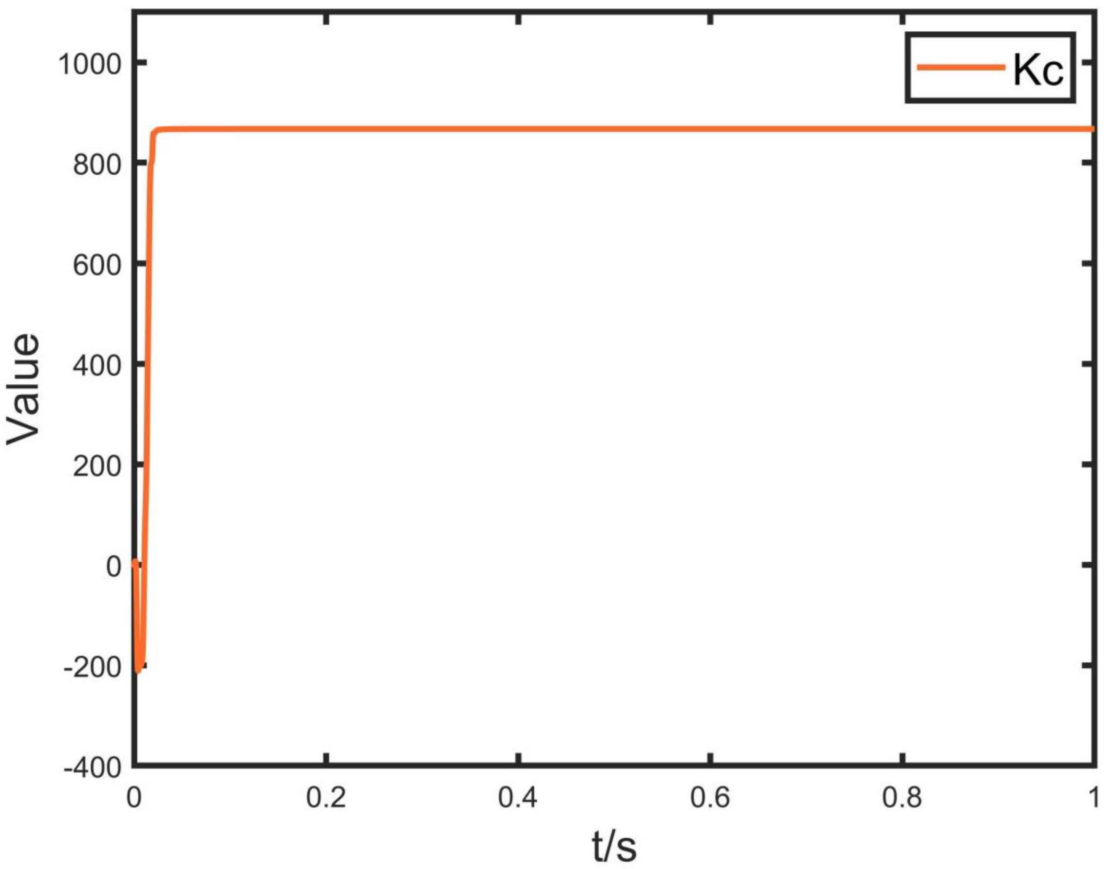
APC is used to adjust the value in the LADRC controller in real-time in this paper. When the photovoltaic array is conducive to the stability analysis of this system, it provides a novel method to improve the stability of the controller. Formula (24) gives the adaptive law of . The adaptive adjustment curve of is shown in Figure 6 and Figure 12. It shows that the adaptive adjustment curve of changes with the change of external conditions.
Assumption 1.
In consideration of tracking error , take the derivative of :
The design of control law is as follows:
where is any positive parameter.
Substitute Formulas (22) and (23) by Formula (21) to obtain:
4. Stability Analysis
Theorem 1.
According to the expression of the system in Equation (16). In this paper, the control scheme is designed according to Formula (23), and the following adaptive laws shall be applied to make the hypothesis valid.
Assumption 2.
All signals in the system are bounded and the tracking error converges to 0.
Proof of Theorem 1.
This paper sets the positive definite function as follows:
Derivation of Formula (26):
Substitute Formula (24) by Formula (27) to obtain:
When the tracking error gets close to zero, it is further deduced that:
Substitute Formula (25) by Formula (29) to obtain:
By simplifying the above formula, we can obtain:
when is a positive parameter, we can obtain:
According to Formula (32), is a monotone decreasing function:
It can be seen from and that the system is uniformly stable, but in the stability analysis, it should be proved that the system is uniformly asymptotically stable. Therefore, this paper further deduces the stability of the system by using the Barbalat theorem, which verifies the feasibility of the above stability analysis. □
Theorem 2 (Barbalat theorem).
If is a continuous function and , then
If and are bounded and is a square integrable, then
Therefore, this shows that is square integrable and that is bounded. Therefore, according to Formula (24), it can be determined that is bounded. In summary, the following formula can be obtained through the deduction of the Barbalat theorem.
Therefore, when , is close to 0, so . Therefore, according to , can be further deduced. Therefore, it can be explained that the system is uniformly asymptotically stable at this time. Therefore, is bounded, is bounded and converges to 0.
5. Simulation and Discussion
In this chapter, the photovoltaic array of 3*1 is taken as the research object, and the feasibility of the MPPT control method proposed in this paper is verified through MATLAB simulation experiments. Compared with the MPPT control method of the traditional LADRC controller, the superiority of this method is verified. The parameters of photovoltaic cells, boost converters and control algorithms are shown in Table 1, Table 2 and Table 3.

Table 1.
PV cell Parameters.

Table 2.
Boost converter parameters.

Table 3.
MPPT controller parameters.
Example 1.
In order to prove that the MPPT control strategy combined with PSO and A-LADRC can effectively and rapidly track the MPP under the external conditions of uniform light, this paper makes the following simulation states for the simulation environment under uniform light. (1) Experimental environment 1: the light condition of the photovoltaic array is set to 1000 W/m2, and the temperature is set to 25 °C. (2) the change curve of light conditions of photovoltaic array is shown in Figure 7, and the temperature is set at 25 °C. (3) The light conditions of the photovoltaic array is set as 1000 W/m2, and the temperature change curve is shown in Figure 9. On the basis of the above three external conditions, the traditional P&O method, the control method combining PSO with LADRC and the control method combining PSO with A-LADRC are selected as the MPPT control strategy. The simulation results of the three methods are compared and discussed.
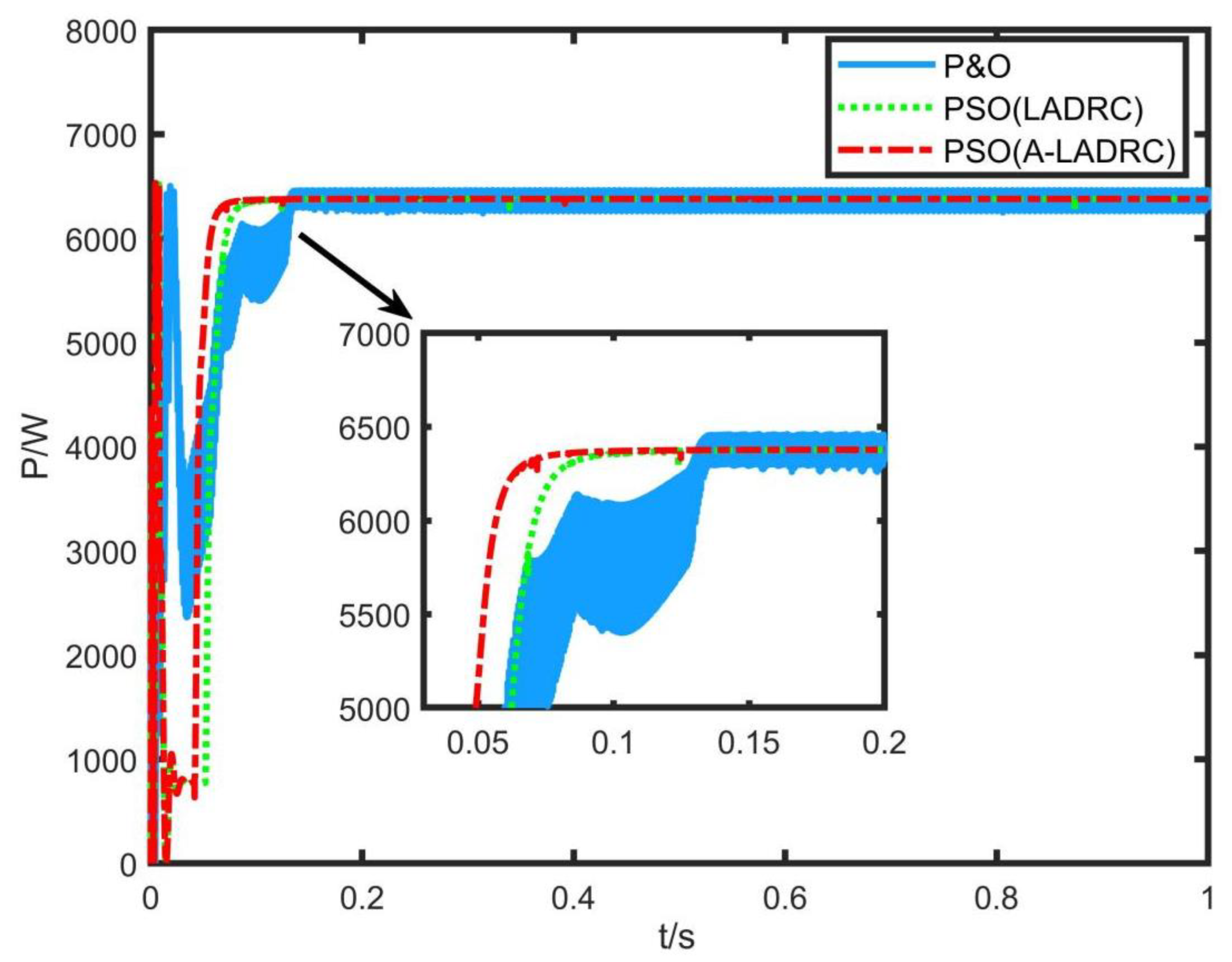
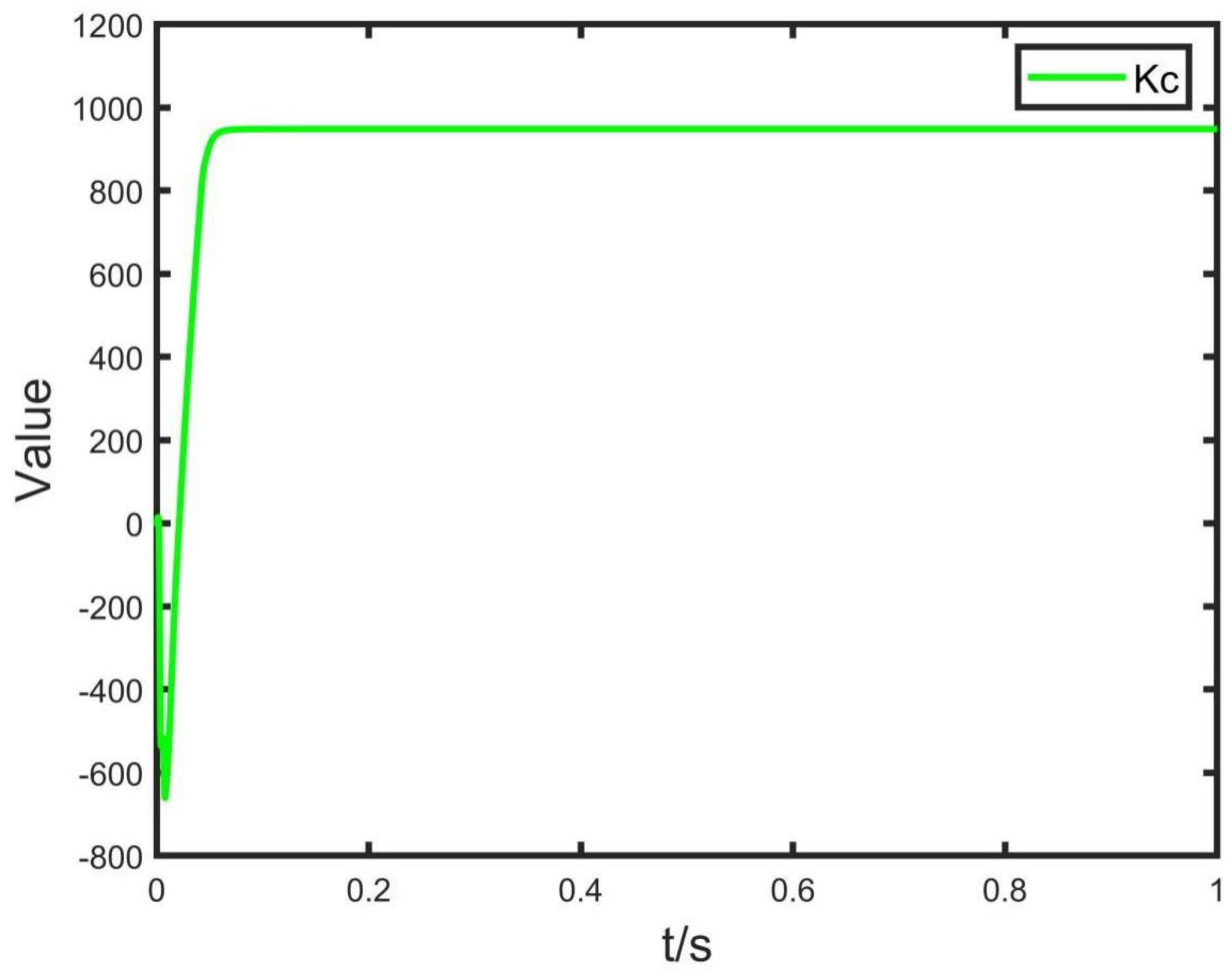
Figure 5 shows the MPPT effect of the traditional P&O method, the control method combining PSO with LADRC and the control method combining PSO with A-LADRC under the experimental environment 1 with uniform light. The traditional P&O method is stable at 0.13 s, but it oscillates near the MPP. The control method of PSO combined with LADRC completes MPPT in 0.1 s, while the method proposed in this paper tracks the MPP in 0.06 s, which is a faster response speed and higher control accuracy than the P&O method. The change curve of under uniform light is shown in Figure 6. The value of is adjusted to the optimal value with the change of external conditions, so as to optimize the performance of the controller.
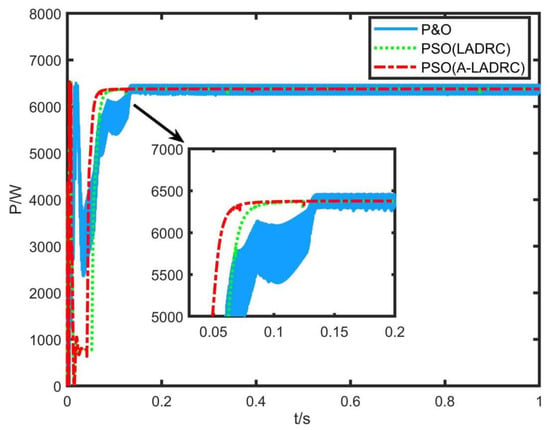
Figure 5.
Output power of photovoltaic array under uniform illumination.
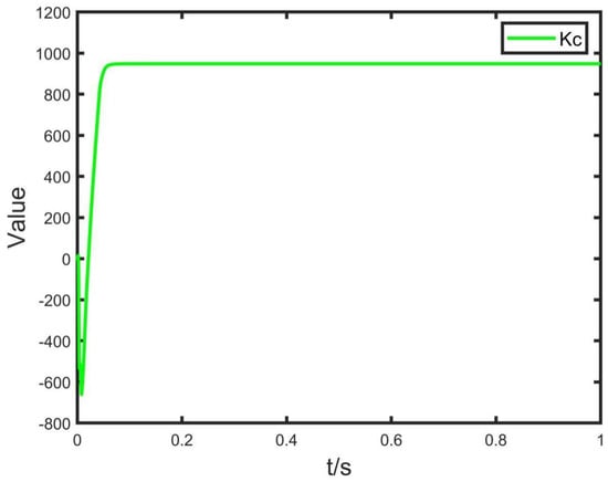
Figure 6.
Adaptive adjustment curve of .
.
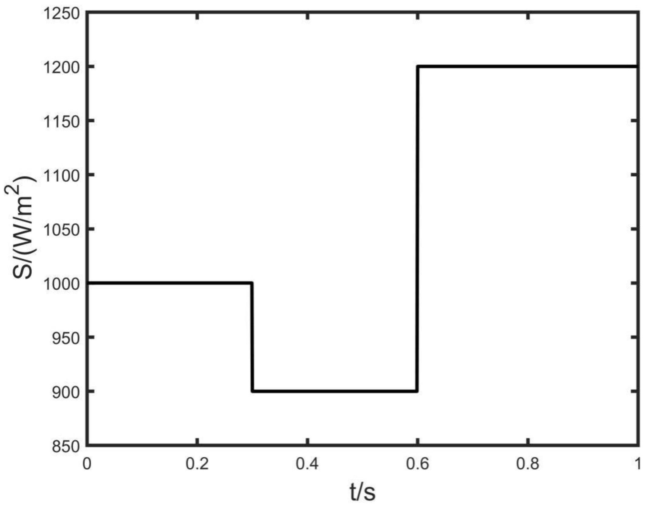
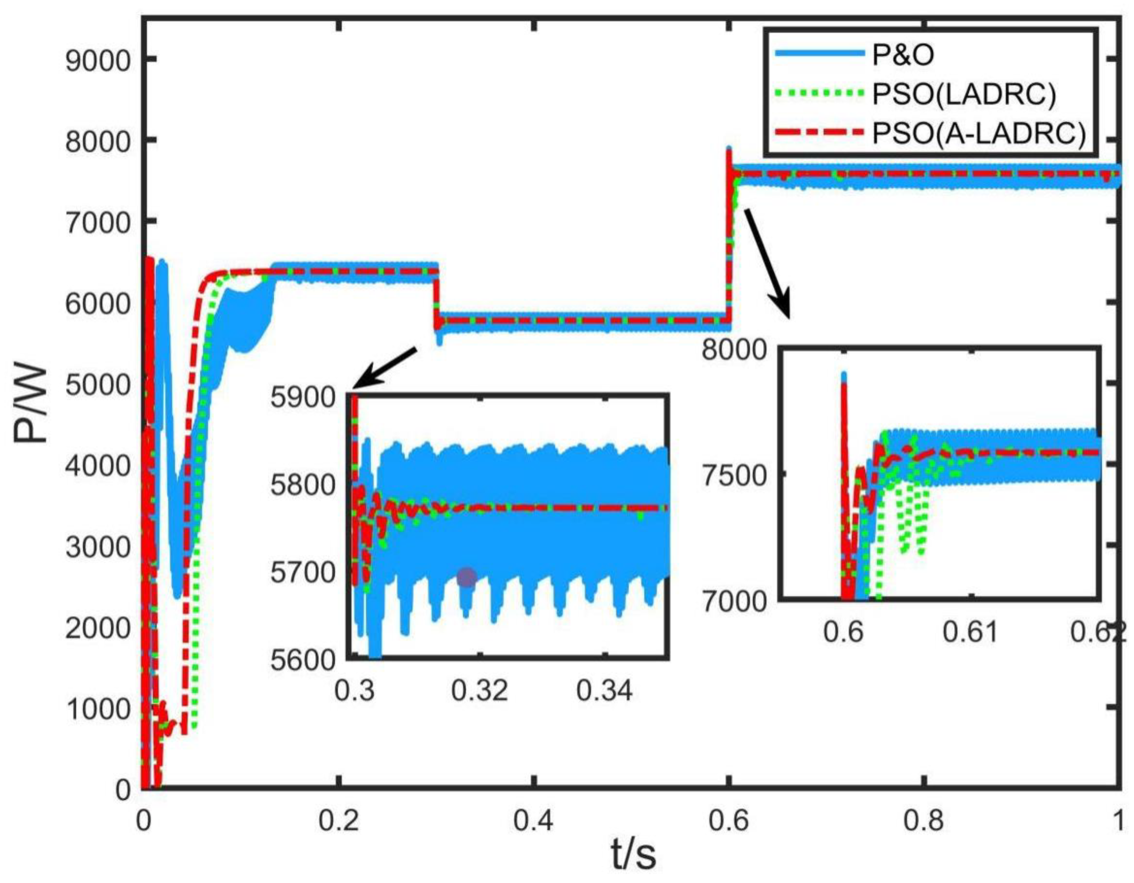
Figure 7 shows the curve of light intensity change of the whole photovoltaic array. In 0.3 s, the light intensity drops from 1000 W/m2 to 900 W/m2. At 0.6 s, the light intensity increases from 900 W/m2 to 1200 W/m2. Figure 8 shows that when the light intensity decreases, the output power under P&O control reaches a stable state at 0.31 s, but the overshoot amplitude is 281.92 W during the transient regulation process and the output power under the control of PSO combined with LADRC returns to a stable state at 0.32 s; The output power under the control of PSO combined with A-LADRC recovers to the stable state at 0.315 s, and the power fluctuation under the control of this method is small in the transient process. When the light intensity increases at 0.6 s, the three MPPT control methods can still effectively track the MPP. The method proposed in this paper makes the output power return to the stable state at 0.61 s. Compared with the P&O method and PSO combined with LADRC method, this method has a shorter transient regulation process and smaller fluctuations, and the tracking accuracy is higher.
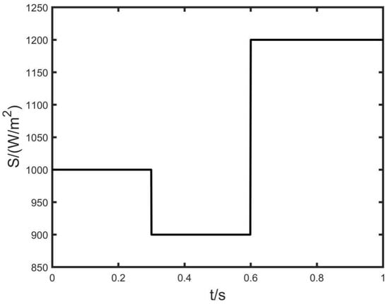
Figure 7.
Variation curve of photovoltaic array light intensity.
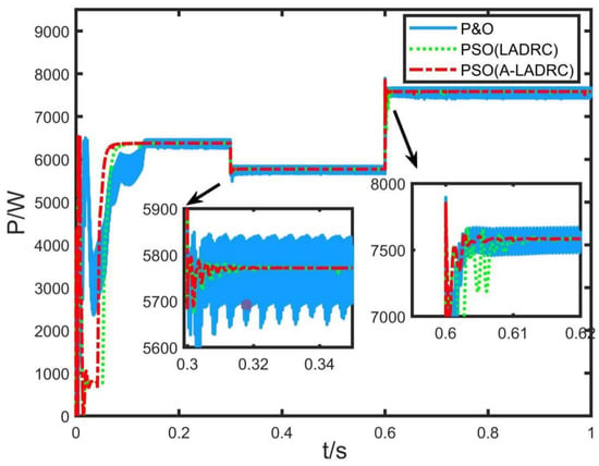
Figure 8.
Output power of photovoltaic array when changing light intensity.
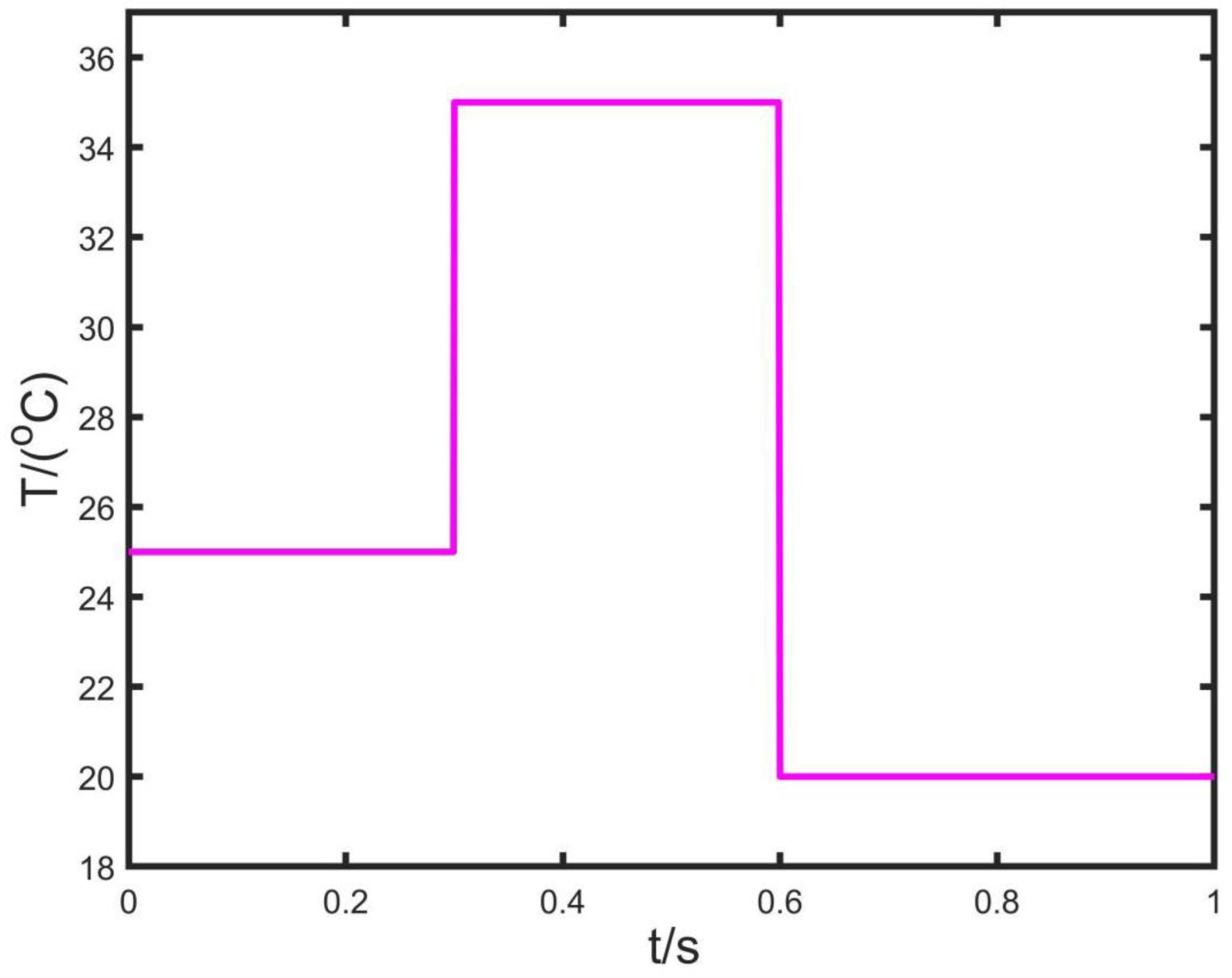
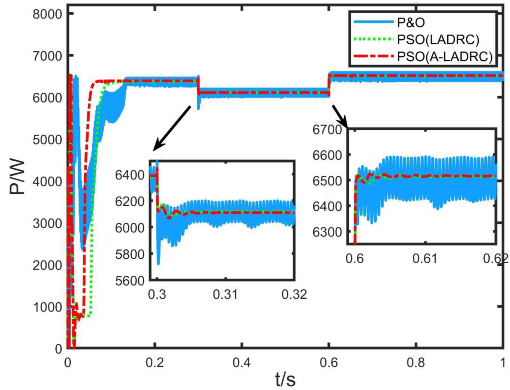
Figure 9 shows the temperature change curve of the entire photovoltaic array. At 0.3 s and 0.6 s, the temperature of the photovoltaic array changes. At 0.3 s, the temperature rises from 25 °C to 35 °C. The temperature decreases from 35 °C to 20 °C at 0.6 s. Figure 10 shows the MPPT effect controlled by the P&O method, the PSO combined with LADRC method and the PSO combined with A-LADRC method when the temperature of photovoltaic array changes. When the temperature changes, the three methods can effectively track the MPP at the current temperature again, but the traditional P&O method has a large overshoot when the temperature rises. Therefore, the introduction of LADRC can effectively suppress the interference caused by temperature changes.
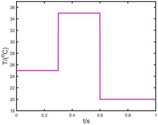
Figure 9.
Temperature change curve of PV array.
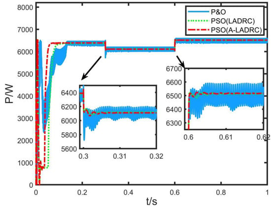
Figure 10.
Output power of photovoltaic array when temperature is changed.
Example 2.
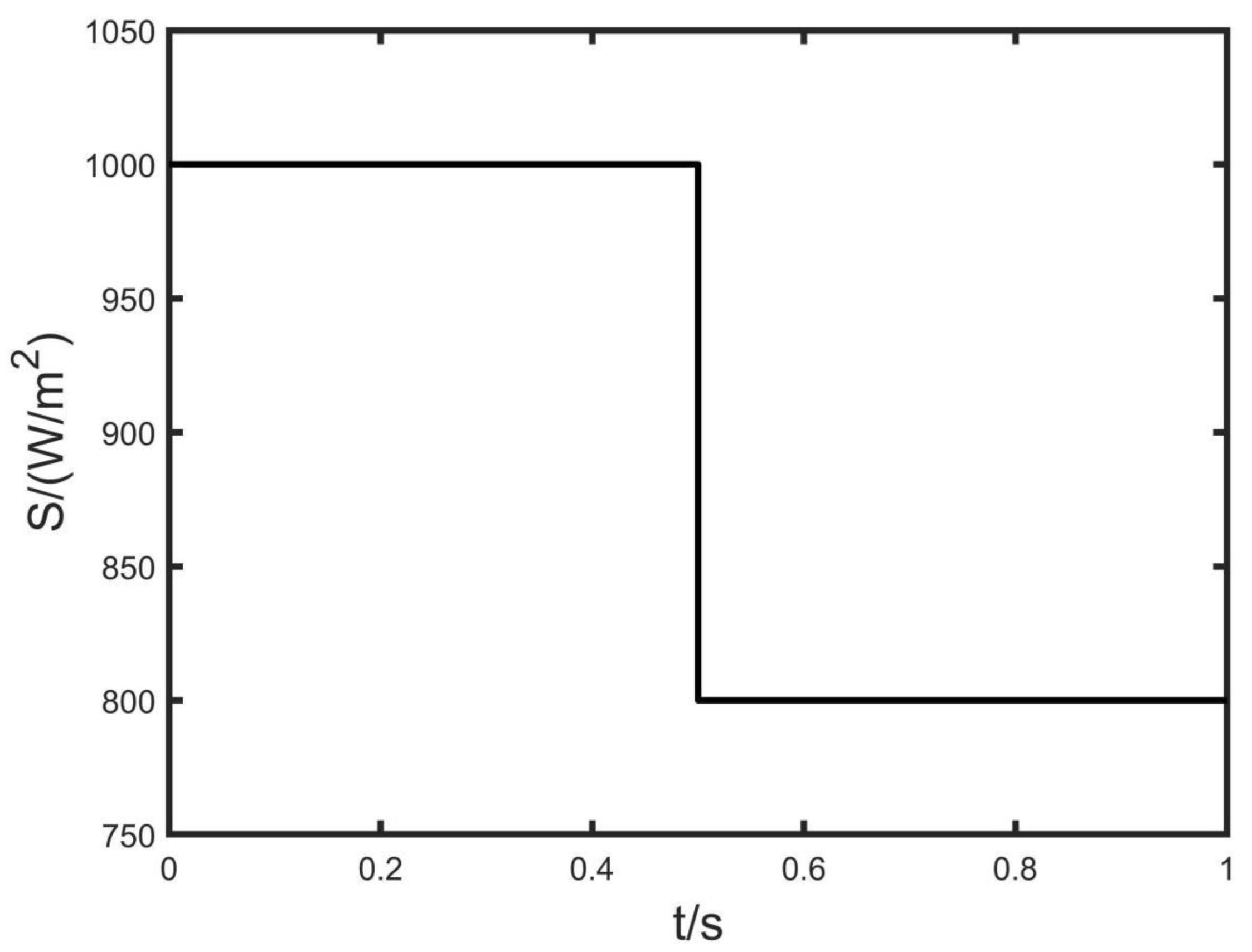
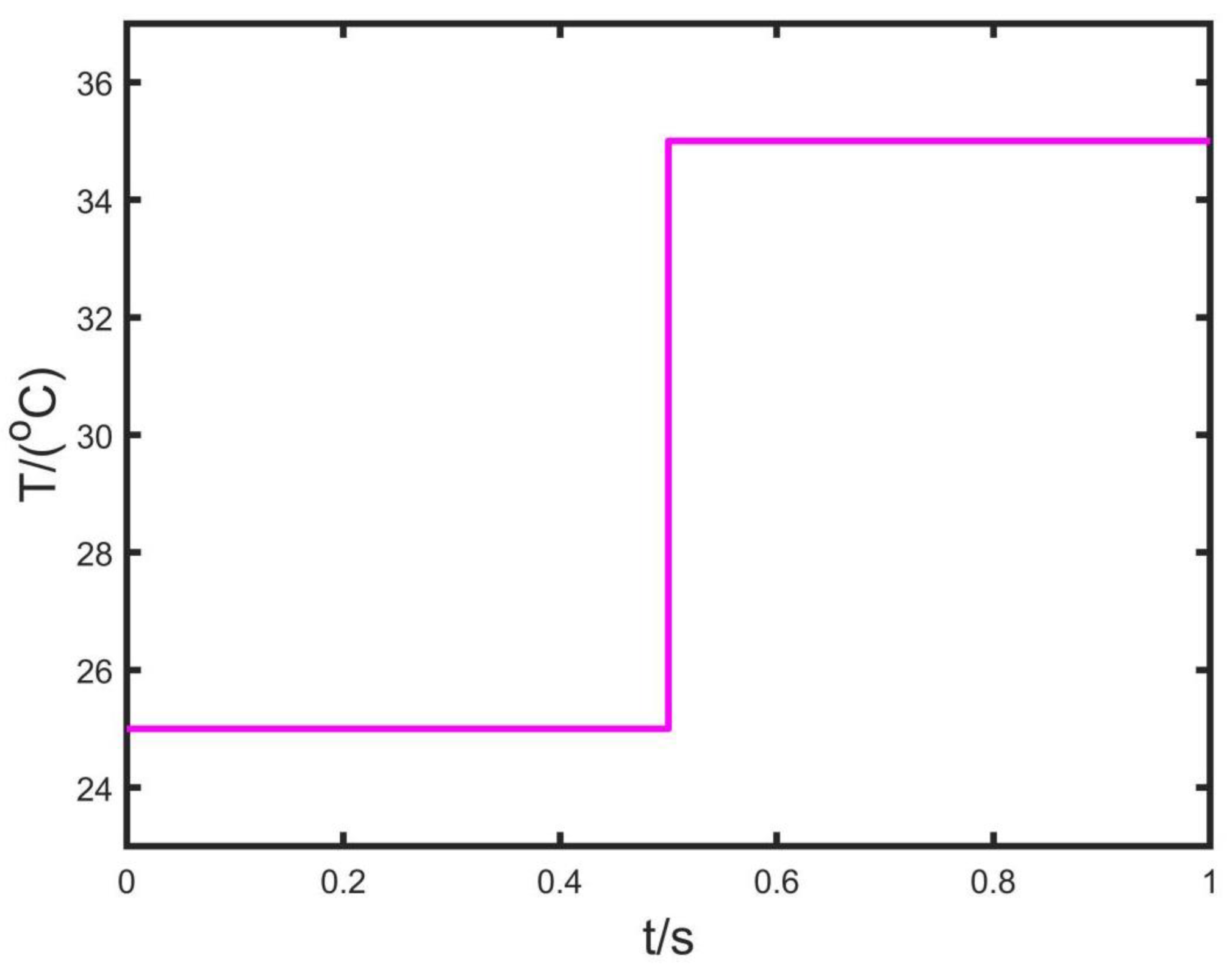
In order to prove that the MPPT control strategy combined with PSO and A-LADRC can effectively and rapidly track the MPP under the condition of local shadow, this paper makes the following simulation states for the simulation environment under the condition of local shadow. (1) Experimental environment 1: the light conditions of photovoltaic cells PV1, PV2 and PV3 is set to 1000 W/m2, 800 W/m2 and 400 W/m2, respectively. The temperature of the PV cell is set at 25 °C. (2) Experimental environment 2: the light intensity change curve of photovoltaic cell PV1 is shown in the figure, and the light intensity of PV2 and PV3 remains unchanged. The temperature of the PV cell is set at 25 °C. (3) Experimental environment 3: the light conditions of photovoltaic cells PV1, PV2 and PV3 is set to 1000 W/m2, 800 W/m2 and 400 W/m2, respectively. The temperature change curve of photovoltaic cell PV1 is shown in the figure. The temperature of photovoltaic cells PV2 and PV3 remain unchanged. Through the above three external conditions, we compare the performance of the A-LADRC controller under local shadow conditions with that of PI and LADRC, and compare and discuss the simulated images.
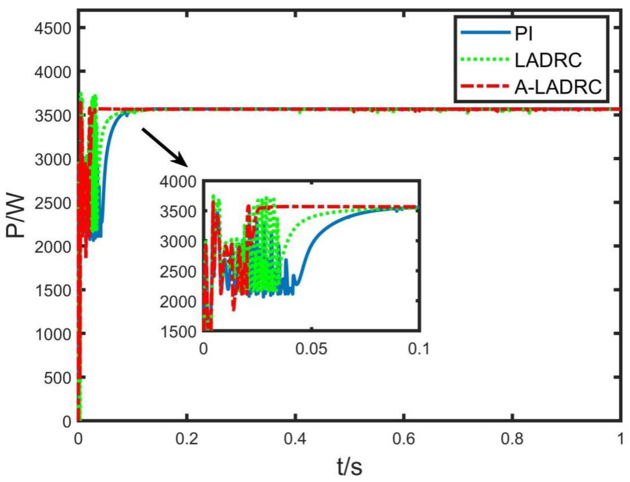
Figure 11 shows the tracking process of the MPPT controller based on the PSO algorithm optimized by the LADRC controller and then by the A-LADRC controller under the condition of local shadows. Figure 11 shows that the PSO algorithm can effectively solve the multi-peak problem of the P-V output curve caused by local shadows, and can accurately find the MPP. The output power under A-LADRC control is stable at 0.03 s, while that under LADRC control is stable at 0.08 s and that under PI control is stable at 0.95 s. Therefore, the A-LADRC controller has a shorter response time and a faster response speed. The change curve of under local shadow condition is shown in Figure 12. At this time, the value of is adjusted compared with that under uniform lighting conditions, which improves the control performance of the controller under this external condition.
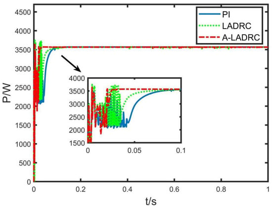
Figure 11.
Output power of PV array under local shadows.
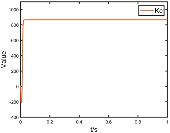
Figure 12.
Adaptive adjustment curve of under local shadow.
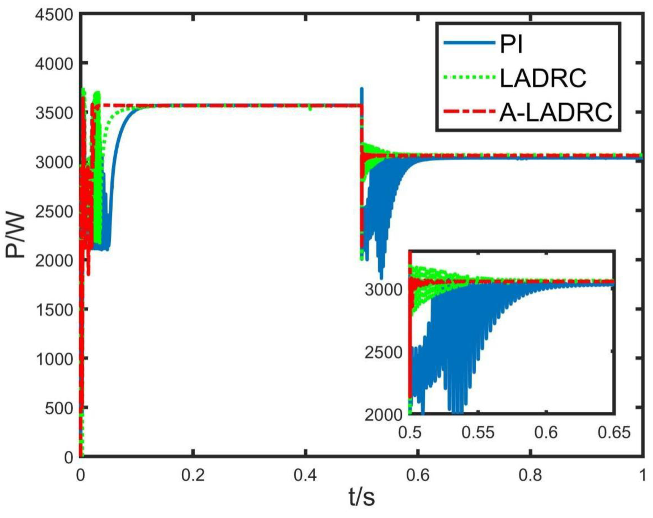
Figure 13 shows the curve of light intensity change of photovoltaic cell PV1. At 0.5 s, the light intensity drops from 1000 W/m2 to 800 W/m2. Figure 14 shows the MPPT effect controlled by PI, LADRC and A-LADRC under the light condition of PV1 beam. The results show that when the illumination conditions change, the output power under PI control has a large overshoot fluctuation, and the system recovery time is too long. The output power under the control of LADRC oscillates in the range of 0.5–0.58 s, and the amplitude of the oscillation is 396.98 W. However, A-LADRC effectively suppressed the oscillation caused by the interference caused by PV1 light intensity, and returned to a stable state at 0.53 s. It can be seen from the comparative analysis that under the local shadow condition, the A-LADRC controller improves the transient process caused by the change of PV1 light intensity and enhances the anti-interference ability.
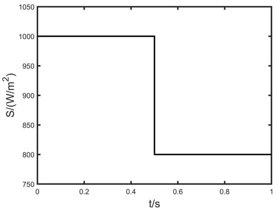
Figure 13.
Variation curve of photovoltaic cell PV1 light intensity.
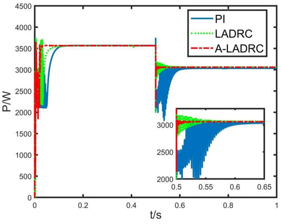
Figure 14.
Photovoltaic array output power by changing PV1 light intensity.
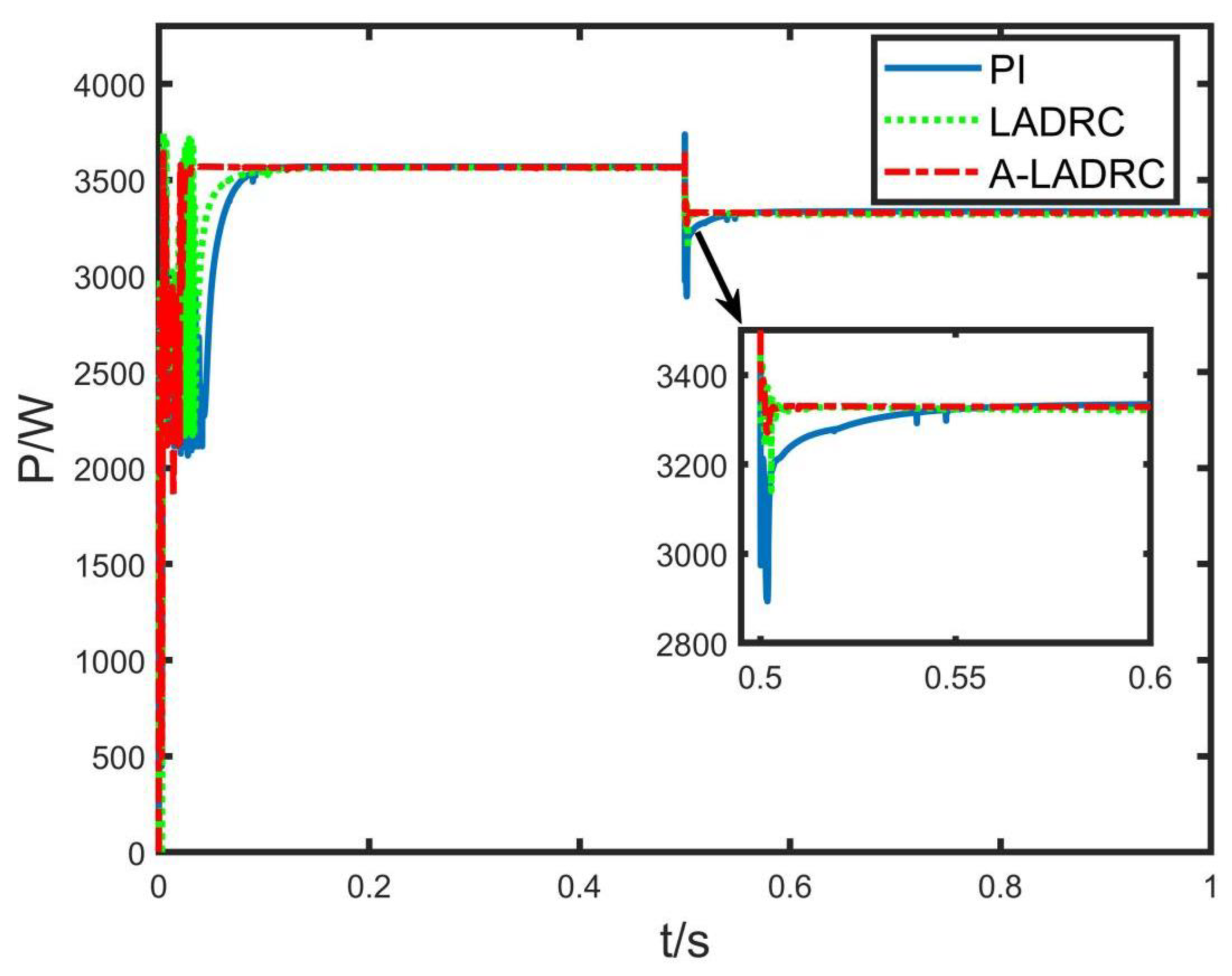
Figure 15 shows the temperature change curve of the photovoltaic cell PV1, where the light intensity increases from 25 °C to 35 °C at 0.5 s. Figure 16 shows the MPPT effect controlled by PI, LADRC and A-LADRC when the temperature of the PV cell PV1 changes. The results show that when the PV1 temperature changes, the tracking effect of the controller combined with PSO and PI fluctuates greatly, and it returns to the stable state again after 0.05 s, with a long adjustment time. The output power oscillation amplitude under the control of LADRC is 286.48 W, and the adjustment time is 0.007 s. The oscillation amplitude of output power under A-LADRC control is 112.57 W, and the adjustment time is 0.002 s. The results show that when the temperature of the PV cell PV1 changes, the other two controllers, except for the PI controller, can effectively suppress the interference. However, A-LADRC has good anti-interference ability and control performance.
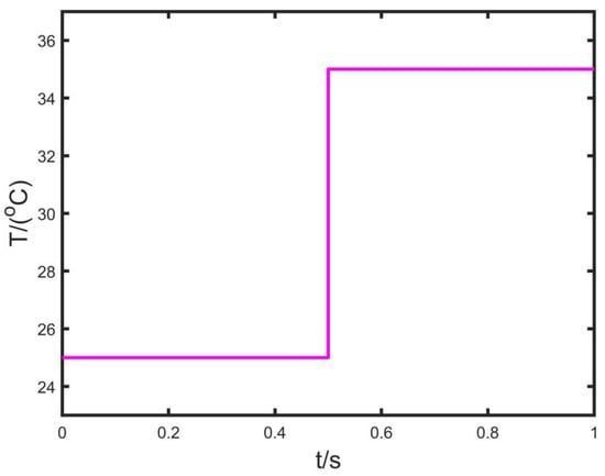
Figure 15.
PV cell PV1 temperature change curve.
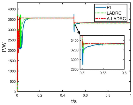
Figure 16.
Output power of photovoltaic array when PV1 temperature is changed.
In Example 1, the traditional P&O method, the MPPT control method combining PSO with LADRC and the MPPT control method combining PSO with A-LADRC under uniform lighting conditions are analyzed. The comparison results show that the traditional P&O method can effectively track the MPP, but it will produce oscillations near the MPP, and this method cannot effectively achieve MPPT under local shadows. The introduction of LADRC gives the MPPT control algorithm based on the PSO algorithm a faster tracking speed, and enhances the ability to suppress disturbance when light intensity or temperature occurs. The introduction of APC makes the parameters of the controller adjust according to the changes of external conditions. Thus, the control performance of the controller under uniform illumination is enhanced. In Example 2, this paper compares PSO with PI, LADRC and A-LADRC combined methods under local shadow. The results show that PSO can effectively track the MPP under local shadows, and the application of LADRC can optimize its tracking speed and anti-interference capability. The A-LADRC controller also shows good control ability under local shadows. The time-varying parameter enables the controller to cope with the changes of external conditions effectively, avoiding the limitation of parameter solidification on controller performance. Therefore, the MPPT method proposed in this paper has good control performance under various external conditions and external disturbances.
6. Conclusions
Aiming at the MPPT problem of photovoltaic array in photovoltaic power generation systems, this paper proposes an MPPT control method that combines the PSO algorithm with a A-LADRC controller. In the design of the MPPT control method, the PSO algorithm is used to find the MPP in the PV output characteristic curve of the photovoltaic array and make the photovoltaic array always work near the MPP and output the current voltage as the reference voltage. Then, the reference voltage is tracked by the A-LADRC controller. In the A-LADRC controller, LESO observes the total disturbance in the system and can also naturally decoupage the strongly coupled part of the system. LESF compensates for the total disturbance of the system and enhances the anti-interference ability of the controller. Meanwhile, APC is introduced into LADRC to adjust parameter . This method eliminates the tracking error caused by parameter deviation, solves the problem of the controller being unable to effectively deal with complex external conditions due to parameter solidification and enhances the adaptive ability of the controller in the face of complex and variable external disturbances. Meanwhile, the proposed control method provides a new way for Lyapunov stability analysis. The simulation results show that the MPPT method of PSO combined with A-LADRC can track the MPP more rapidly under both uniform illumination and local shadows. When the external conditions of photovoltaic array change, the method can still track the MPP rapidly and accurately and has a strong anti-interference ability. Compared with MPPT methods such as P&O, PSO combined with PI and LADRC, the method proposed in this paper has a better ability to suppress disturbance and a faster response speed.
Finally, A−LADRC needs further research and improvement in the MPPT control strategy. Due to the lack of relevant instruments, this paper only simulates the control strategy. Later, we will carry out experimental research on the algorithm and further improve the algorithm based on specific experimental data. Meanwhile, in MPPT control, we can continue to explore the control effect of other intelligent algorithms combined with the A-LADRC controller.
Author Contributions
M.Z.: contributed to the conception of the study, performed the experiment, performed the data analyses, and wrote the manuscript; K.Z. and T.Z.: contributed to the conception of the study; J.X., Y.G., S.C. and Z.Q.: helped perform the analysis with constructive discussions. All authors have read and agreed to the published version of the manuscript.
Funding
This research received no external funding.
Institutional Review Board Statement
Not applicable.
Informed Consent Statement
Not applicable.
Data Availability Statement
Not applicable.
Conflicts of Interest
The authors declare no conflict of interest.
References
- Zhao, F.Z.; Wang, X.F.; Zhu, T.H. Power Dynamic Decoupling Control of Grid-Forming Converter in Stiff Grid. IEEE Trans. Power Electron. 2022, 37, 9073–9088. [Google Scholar] [CrossRef]
- Wang, B.; Wang, Q.; Wei, Y.M. Role of renewable energy in China’s energy security and climate change mitigation: An index decomposition analysis. Renew. Sustain. Energy Rev. 2018, 90, 187–194. [Google Scholar] [CrossRef]
- Lucas, S.; Xavier Allan, F. Cupertino, Heverton, A. Pereira, Ancillary services provided by photovoltaic inverters: Single and three phase control strategies. Comput. Electr. Eng. 2018, 70, 102–121. [Google Scholar]
- Zhao, X.; Luo, D. Driving force of rising renewable energy in China: Environment, regulation and employment. Renew. Sustain. Energy Rev. 2017, 68, 48–56. [Google Scholar] [CrossRef]
- Zhao, F.Z.; Wang, X.F.; Zhou, Z.C.; Harnefors, L.; Svensson, J.R.; Kocewiak, L.H.; Gryning, M.P.S. Control Interaction Modeling and Analysis of Grid-Forming Battery Energy Storage System for Offshore Wind Power Plant. IEEE Trans. Power Syst. 2022, 37, 497–507. [Google Scholar] [CrossRef]
- Sfirat, A.; Gontean, A.; Bularka, S. A New Method for MPPT Algorithm Implementation and Testing, Suitable for Photovoltaic Cells. Adv. Electr. Comput. Eng. 2018, 18, 53–60. [Google Scholar] [CrossRef]
- De Brito, M.A.G.; Galotto, L.; Sampaio, L.P.; e Melo, G.d.A.; Canesin, C.A. Evaluation of the Main MPPT Techniques for Photovoltaic Applications. IEEE Trans. Ind. Electron. 2013, 60, 1156–1167. [Google Scholar] [CrossRef]
- Gupta, A.; Chauhan, Y.K.; Pachauri, R.K. A comparative investigation of maximum power point tracking methods for solar PV system. Sol. Energy 2016, 136, 236–253. [Google Scholar] [CrossRef]
- Celikel, R.; Boztas, G.; Aydogmus, O. A system identification-based MPPT algorithm for solar photovoltaic pumping system under partial shading conditions. Energy Sources Part A Recovery Util. Environ. Eff. 2022, 44, 5199–5214. [Google Scholar] [CrossRef]
- Alik, R.; Jusoh, A. An enhanced P&O checking algorithm MPPT for high tracking efficiency of partially shaded PV module. Sol. Energy 2018, 163, 570–580. [Google Scholar]
- Hashemzadeh, S.M. A new model-based technique for fast and accurate tracking of global maximum power point in photovoltaic arrays under partial shading conditions. Renew. Energy 2019, 139, 1061–1076. [Google Scholar] [CrossRef]
- Kumar, V.; Ghosh, S.; Naidu, N.K.S. Load voltage-based MPPT technique for standalone PV systems using adaptive step. Int. J. Electr. Power Energy Syst. 2021, 128, 106732. [Google Scholar] [CrossRef]
- Liu, C.; Zheng, L.; Sun, Y.; Mu, Z. MPPT based on improved bacterial foraging algorithm. J. Sol. Energy 2021, 9, 83–89. [Google Scholar]
- Hayder, W.; Sera, D.; Ogliari, E.; Lashab, A. On Improved PSO and Neural Network P&O Methods for PV System under Shading and Various Atmospheric Conditions. Energies 2022, 15, 7668. [Google Scholar] [CrossRef]
- Ngo, S.; Chiu, C.-S.; Ngo, T.-D. A Novel Horse Racing Algorithm Based MPPT Control for Standalone PV Power Systems. Energies 2022, 15, 7498. [Google Scholar] [CrossRef]
- Vankadara, S.K.; Chatterjee, S.; Balachandran, P.K.; Mihet-Popa, L. Marine Predator Algorithm (MPA)-Based MPPT Technique for Solar PV Systems under Partial Shading Conditions. Energies 2022, 15, 6172. [Google Scholar] [CrossRef]
- Liu, F.; Duan, S.; Liu, F.; Liu, B.; Kang, Y. A Variable Step Size INC MPPT Method for PV Systems. IEEE Trans. Ind. Electron. 2008, 55, 2622–2628. [Google Scholar] [CrossRef]
- Mohanty, S.; Subudhi, B.P.K.R. A New MPPT Design Using Grey Wolf Optimization Technique for Photovoltaic System Under Partial Shading Conditions. IEEE Trans. Sustain. Energy 2016, 7, 181–188. [Google Scholar] [CrossRef]
- Bianconi, E.; Calvente, J.; Giral, R.; Mamarelis, E.; Petrone, G.; Ramos-Paja, C.A.; Spagnuolo, G.; Vitelli, M. A fast current-based MPPT technique employing sliding mode control. IEEE Trans. Ind. Electron. 2013, 60, 1168–1178. [Google Scholar] [CrossRef]
- Kakosimos, P.E.; Kladas, A.G.; Manias, S.N. Fast photovoltaic-system voltage-or current-oriented MPPT employing a predictive digital current-controlled converter. IEEE Trans. Ind. Electron. 2013, 60, 5673–5685. [Google Scholar] [CrossRef]
- Kakosimos, P.E.; Kladas, A.G. Implementation of photovoltaic array MPPT through fixed step predictive control technique. Renew. Energy 2011, 36, 2508–2514. [Google Scholar] [CrossRef]
- Laib, A.; Krim, F.; Talbi, B.; Sahli, A. A predictive control scheme for large-scale grid-connected PV system using high-level NPC inverter. Arab. J. Sci. Eng. 2020, 45, 1685–1701. [Google Scholar] [CrossRef]
- Xue, J.; Zhuang, K.; Zhao, T.; Zhang, M.; Qiao, Z.; Cui, S.; Gao, Y. Speed Tracking Control of High-Speed Train Based on Particle Swarm Optimization and Adaptive Linear Active Disturbance Rejection Control. Appl. Sci. 2022, 12, 10558. [Google Scholar] [CrossRef]
- Zhang, M.; Zhuang, K.; Zhao, T.; Chen, X.; Xue, J.; Qiao, Z.; Cui, S.; Gao, Y. Bus Voltage Control of Photovoltaic Grid Connected Inverter Based on Adaptive Linear Active Disturbance Rejection. Energies 2022, 15, 5556. [Google Scholar] [CrossRef]
- Liu, C.; Cheng, Y.; Liu, D.; Cao, G.; Lee, I. Research on a LADRC Strategy for Trajectory Tracking Control of Delta High-Speed Parallel Robots. Math. Probl. Eng. 2020, 2020, 9014317. [Google Scholar] [CrossRef]
- Ma, X.J.; Zeng, Q.H.; Yuan, D. Speed tracking of PMSM drive for hybrid electric vehicle based on LADRC. In Proceedings of the IEEE Conference and Expo Transportation Electrification Asia-Pacific (ITEC Asia-Pacific), Beijing, China, 31 August–3 September 2014; Volume 31. [Google Scholar]
- Liu, K.; He, J.; Luo, Z.; Shen, X.; Liu, X.; Lu, T. Secondary Frequency Control of Isolated Microgrid Based on LADRC. IEEE Access 2019, 7, 53454–53462. [Google Scholar] [CrossRef]
- Wang, Z.; Yu, C.; Li, M.; Yao, B.; Lian, L. Vertical Profile Diving and Floating Motion Control of the Underwater Glider Based on Fuzzy Adaptive LADRC Algorithm. J. Mar. Sci. Eng. 2021, 9, 698. [Google Scholar] [CrossRef]
- Kang, Z.-J.; Zhao, K.; Li, S.; Liu, Z. Design of a real-time three-axis controller for contour error reduction based on model predictive control. Proc. Inst. Mech. Eng. Part C J. Mech. Eng. Sci. 2022, 236, 9241–9254. [Google Scholar] [CrossRef]
- Vimalarani, C.; Kamaraj, N.; Chitti Babu, B. Improved method of maximum power point tracking of photovoltaic (PV) array using hybrid intelligent controller. Optik 2018, 168, 403–415. [Google Scholar] [CrossRef]
- Kumar, C.; Raj, T.D.; Premkumar, M. A new stochastic slime mould optimization algorithm for the estimation of solar photovoltaic cell parameters. Opt. Z. Licht Elektronenoptik J. Light Electronoptic 2020, 223, 223. [Google Scholar] [CrossRef]
- Nguyen, X.H.; Nguyen, M.P. Mathematical modeling of photovoltaic cell/module/arrays with tags in Matlab/Simulink. Environ. Syst. Res. 2015, 4, 24. [Google Scholar] [CrossRef]
- Sudeepika, P.; Khan, G. Analysis of Mathematical Model of PV Cell. Module in Matlab/Simulink Environment. Res. Rev. 2014, 3, 3. [Google Scholar]
- Zhou, D.; Chen, Y. Maximum power point tracking strategy based on modified variable step-size incremental conductance algorithm. Power Syst. Technol. 2015, 39, 1491–1498. [Google Scholar]
- Zhou, X.; Liu, W.; Ma, Y. Analysis of three-phase four-wire shunt active power filter system based on LADRC. High Volt. Eng. 2016, 42, 1290–1299. [Google Scholar]
- Ibrahim, A.; Aboelsaud, R.; Obukhov, S. Improved particle swarm optimization for global maximum power point tracking of partially shaded PV array. Electr. Eng. 2019, 101, 443–455. [Google Scholar] [CrossRef]
- Wang, Z.; Zhao, T. Adaptive-based linear active disturbance rejection attitude control for quadrotor with external disturbances. Trans. Inst. Meas. Control 2021, 44, 286–298. [Google Scholar] [CrossRef]
- Cong, M.X.; Zhao, T. Active Disturbance Rejection Trajectory Tracking Control of Manipulator Based on Neural Network. In Proceedings of the 2020 Chinese Control and Decision Conference, Hefei, China, 22–24 August 2020; pp. 1732–1737. [Google Scholar]
- Liu, W.; Zhao, T.; Wu, Z.; Huang, W. Linear active disturbance rejection control for hysteresis compensation based on backpropagation neural networks adaptive control. Trans. Inst. Meas. Control. 2020, 43, 915–924. [Google Scholar] [CrossRef]
Publisher’s Note: MDPI stays neutral with regard to jurisdictional claims in published maps and institutional affiliations. |
© 2022 by the authors. Licensee MDPI, Basel, Switzerland. This article is an open access article distributed under the terms and conditions of the Creative Commons Attribution (CC BY) license (https://creativecommons.org/licenses/by/4.0/).

