Abstract
Relay-based traffic control systems are still used in railway control systems. Their correctness is most often verified by manual analysis, which does not guarantee correctness in all conditions. Passenger safety, control reliability, and failure-free operation of all components require formal proof of the control system’s correctness. Formal evidence allows certification of control systems, ensuring that safety will be maintained in correct conditions and the in event of failure. The operational safety of systems in the event of component failure cannot be manually checked practically in the event of various types of damage to one component, pairs of components, etc. In the article, we describe the methodology of automated system verification using the IMDS (integrated model of distributed systems) temporal formalism and the Dedan tool. The novelty of the presented verification methodology lays in graphical design of the circuit elements, automated verification liberating the designer from using temporal logic, checking partial properties related to fragments of the circuit, and fair verification preventing the discovering of false deadlocks. The article presents the verification of an exemplary relay traffic control system in the correct case, in the case of damage to elements, and the case of an incorrect sequence of signals from the environment. The verification results are shown in the form of sequence diagrams leading to the correct/incorrect final state.
1. Introduction
The safe operation of railway traffic is ensured by railway traffic control systems. Light signals, barriers at level crossings, and detection systems able to detect railway vehicles in a particular part of tracks are some tools used to prevent disasters such as train-to-train and train-to-car collisions. These devices must be appropriately coordinated and managed by logic systems that ensure work safety even in numerous device failures, including own (internal) ones.
Relay technology has traditionally been used to construct control systems. A control system is a network of interconnected analog and stateful electromechanical components, such as a power supply, circuit breakers, relays, fuses, etc. Relays can be considered logical elements as they can only be energized or de-energized, although this is a huge simplification. The relays do not operate immediately (they need time to change state), and there are transients when the state changes. As a result, the simple implementation of a logic function is, in fact, a rough abstraction of a series of unstable intermediate states. The relays are also prone to errors that could cause the system to malfunction or delay its operation. Therefore, relay networks are often built redundantly to minimize the impact of errors and ensure safety (at the expense of longevity) in all circumstances.
Railway traffic control devices can be constructed in various technologies, including interlocking and executive systems. Mechanical solutions are the oldest. There are relay, electronic, and computer devices among the electrical solutions. Relay solutions have been widely developed in Poland since the 1950s. The experience related to the construction of these systems and their operation allowed for formulating general rules for the construction of such circuits. These rules would allow avoiding typical abnormal behavior in the event of faults or disturbances in their operation. One of the basic rules is to use relays with better than standard and additional properties.
It can be said that the application of such principles is a necessary condition to construct a system that will meet the requirements (in the event of damage it will come in a deterministic way to the safe state specified by the designer) but not sufficient to confirm that it will behave correctly under all possible circumstances.
Railway traffic control systems should be deterministic automata. Their correct operation is based on states strictly defined at the design stage. The states that should be reached in the event of potential failure and/or incorrect command are also specified.
The Eap line block [1], described in more detail in Section 3, performs its functions thanks to logic circuits (combinational and sequential) implemented through relay circuits. Potential damage to relays and other elements (resistors, diodes, capacitors, transformers) used in the construction of railway traffic control systems are classified [2,3]. In developing new solutions or modifying the existing ones, the discussed classifications should be used to verify whether the device will behave in an intended manner due to a defect and/or incorrect command.
In order to increase the reliability of the systems, quality standards have been introduced for the components used, design methods, security solutions etc., for example CENELEC, EN50126 [4,5], and EN50129 [3]. System verification undoubtedly helps achieve the highest safety standards SIL4 [6,7]. Verification carried out using traditional methods, by analyzing the system’s operation by a specialist and testing, does not ensure that the system is always working correctly. Formal proof of its correct operation guarantees that the system works properly in every situation. Regarding the sequences of system behavior in response to external forces, and the sequences of systems cooperation, model checking methods based on temporal logic are invaluable. Unfortunately, the great difficulty is the intellectual skills necessary to carry out the verification, requiring the knowledge of temporal logic to formulate the appropriate requirements. Several different approaches to verification are outlined in Section 2.
In this article, we focused on automating the verification process. We used the original formalism of the integrated model of distributed systems [8]. Its unique features supporting automatic verification are:
- The graphic formalism for modeling, having the same semantics as the algebraic model for verification, so there is no need to translate from the description of the system to the verification language [9];
- A limited set of examined features, but verified automatically, without specifying temporal formulas; these are deadlocks and termination;
- Finding partial deadlocks and termination concerning parts of the system or even its individual elements; while the rest of the system may not experience the effects of partial deadlocks/termination, most verifiers find only total deadlocks/termination, and the user has to ask for partial properties by formulating appropriate temporal formulas;
- Fairness of verification is a little-known feature among non-specialists; however, most verifiers are unfair or weakly fair, which can lead to the detection of non-existent deadlocks [10].
In the article, we show the methodology of temporal checking the fragment of the line block system Eap. The correct operation of the system will be demonstrated, as well as the safety of the system, both in the event of an incorrect sequence of signals at the input and in the event of damage to individual components. This methodology is a research contribution of the authors.
The article is structured as follows: Section 2 presents the related work on verifying relay switching systems. Section 3 presents the subject of the study: Eap. Section 4 presents the IMDS verification formalism and the verification environment. Section 5 describes the verification process and results. The summary and subject of further research are described in Section 6.
2. Related Work
Relay systems are still an important part of railway controllers, and more broadly in industrial control systems. Several methods have been developed to verify such systems. Most commonly, the states of systems and state transitions are expressed as Boolean expressions (for example, with BDD graphs) and then verified with verifiers such as Spin [11] or NuSMV [11]. System logic can also be expressed as UML state diagrams [12]. The latter work concerns only the situation of train collisions.
There are several methods of verification of relay systems in the literature. In [13], the RAISE specification and the SAL verifier were used, and in [14], the authors build the Kripke structure directly and verify the properties with SONOLAR SMT in bounded model checking. In [15], the railway network DSL (domain-specific language) specification was used and again bounded model checking in RT-Tester. NORMA [16] has a built-in graphical circuit editor and uses Timed SMV for verification. The article [17] presents the specification in B-Method and verification with ProB.
In the papers [7,18], timed automata were used to model the system and verify it with Uppaal [19]. Automatic observers were used for verification, similar to our method. However, temporal formulas are still required but applied to the observers and not to the system itself.
Many papers concern the verification on a higher abstraction level, in which control systems are treated as black boxes, interchanging signals. For example, in [20,21] B-Method and Atelier-B toolkit are used. The application of CSP‖B and ProB is described in [22]. A similar approach in [23] uses the specification in UML that is converted to B. In [24], two compositional approaches using RT-Tester and NuSMV are proposed. Checking the violation of safety rules expressed as invariants, performed in SMT solver, is described in [25]. Invariant verification using ABS (abstract behavioral specification) and Key-ABS verifier is covered in [26]. The authors of [27] use colored petri nets for modeling interlocking equipment, but without verification. Petri nets can be verified using numerous verifiers, for example [28]. The authors of [29] use the S3 tool providing bounded model checking and theorem proving.
Failure analysis based on system log analysis with Uppaal is presented in [30]. The presented methods of higher-level verification generally require the designer to specify the properties as temporal formulas.
The operation of rail traffic control system under wrong signal sequences, using NuSMV and OCRA (a tool for checking the refinement of temporal contracts), is investigated in [31].
Theorem-proving using PERF, the alternative verification method to the model checking, is applied in [32].
The mentioned verification methods lack the features that are present in our method:
- Specification in languages specific for the verifier rather than a graphical form convenient for the designer;
- Automatic checking only total deadlocks, other properties must be specified as temporal formulas (except [7,18,19]);
- Strong fairness of verification (weak fairness or no fairness leads to the possibility of finding false deadlocks [10]).
3. The Study
3.1. Line Block Eap
The line block is used to regulate the traffic on the open line and is a set of devices that make setting activities addictive directly between two stations or taking into account block sentinels on the open line. By means of a line block, the sequence of trains on the open line is regulated at set intervals of the track and in the set direction of movement on the open line. Driving traffic using a line block is called a fixed distance method, which is a block distance. The devices guarantee adequate safety and efficiency of the traffic. The primary function of the block is to prevent more than one train from being in the controlled distance [33].
There are many technical solutions for line blocks. A popular solution in Poland is a single-block, semi-automatic, relay-type Eap block [1].
The block fragment consists of two sets containing electromagnetic relays, transformers, and small electronic components (diodes, capacitors). Each of the sets is installed at the traffic station located at the end of the route and, in addition to being connected by two wires to the other set (the so-called transmission line, it also has connections with the operator’s panel that allows for issuing commands, monitoring the current state, power supply, and interlocking with which a given station is equipped (Figure 1).
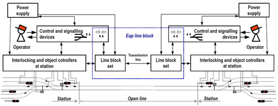
Figure 1.
Illustrative diagram of the Eap line block and its surroundings.
3.2. The Checked Fragment of the System
The subsystem selected for the verification is the fragment of the Eap block. It consists of two relays: switching W and releasing Z. When the block is set towards the station, this subsystem detects the sequential passage of the train through two sections (Jt and Jz) located at the beginning of the station (and at the end of the route at the same time). This enables the personnel operating the equipment to confirm that the train has left the route (only if the W and Z relays are picked up). If the W and Z relays are not picked up, it is impossible to confirm that the train has left the track, and therefore it is impossible to send another train to the track.
The exemplary Eap block subsystem has been studied in several ways. Basic testing concerns the inevitability of a correct operation with the correct sequence of input signals. Correct operation means pick-up and then release of specific relays in the system as a result of receiving a sequence of signals indicating the train’s movement. The next test verifies that the system behaves safely when it is not receiving the input signals in the correct order. An example of such a scenario is the movement of a train in the opposite direction, generating a different sequence of input signals than the basic one. In such a situation, the relays W and Z (Figure 2) should not pick up, which is a safe behavior of the system. Another test is to damage the system and check whether the system is also safe in this case. Of course, the system can be damaged in many ways, and in the case of certification, it would be necessary to investigate all possible, and even multiple, defects. We limit ourselves to two examples of faults: short-circuiting the input with the output of one of the switches (i.e., reacting only to power supply and no reaction to switching) and permanent opening of one of the relay contacts.
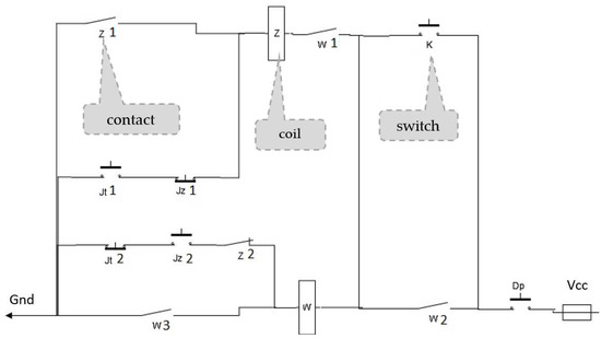
Figure 2.
Schematic diagram of a fragment of the line block Eap.
4. Temporal Verification
Temporal verification (model checking) consists of checking the presence or absence of specific features in the sequence of the system behavior. Such verification makes sense when there are concurrent elements in the system, because the sequence (even in the case of non-determinism) can be easily traced manually. Putting together parallel activities results in such many possible behaviors that it is impossible to trace them. Temporal verification checks all possible system behaviors, giving evidence of a specific action.
Model checking in the IMDS formalism answers questions about deadlock, inevitable process termination, or its possible termination. These features may refer to a specific process or group of processes. An essential feature of model checking is the preparation of evidence, which is an exemplary sequence leading to such a situation, in the case of a deadlock, termination, or non-termination detection. In the case of a deadlock or unsuccessful termination, this sequence is called a counterexample and provides evidence: the sequence that leads to the deadlock is evidence that the processes may be stuck (although there may be other undisplayed deadlock sequences). In the absence of termination, the example sequence occurs in which the processes do not terminate. In the latter case, the counterexample ends in a deadlock or a loop with no way out: both demonstrate that the processes are not terminated.
In case of a positive answer to the question of inevitable or possible termination, the sequence is called a witness and shows an example path to the termination. In the case of inevitable termination, this path is not proof but only an example of how termination is correctly achieved, as there may be many such sequences. Evidence of inevitable termination is the verifier’s response. In the case of possible termination, the path is also the proof.
4.1. Verification Tools: IMDS/Dedan
In our study, we use the integrated model of distributed systems [8] formalism, which we have already used to verify real systems, such as the Karlsruhe production cell [34] or a fragment of the Rome metro [35]. This verification differs in that it is carried out at a low abstraction level of the switching circuits, and the transmitted signals are electrical. However, we believe that formalism is up to the task. IMDS is attractive because it has a graphical version of DA3 distributed automata [9], allowing the design of models in terms of automata, consistent with the intuition of engineers performing verification. The automata-based model fully complies with the IMDS algebraic formalism in which the verification is performed.
The verification is performed in the Dedan tool, which automatically checks three types of temporal properties. The formulas verifying those properties are hidden inside the tool, so the user need not know any temporal login and verification rules. The checked properties concern deadlock and termination. Using those basic properties, higher level features can be expressed and verified. The questions asked when verifying the sample circuit are:
- Testing correct operation and the correct sequence of input signals: will the system inevitably reach the predicted final state, going through all the required states beforehand?
- The introduction of damage and the correct sequence of input signals: whether the system does not reach the final state, but also does not pass through dangerous states?
- Checking the correct system and the incorrect sequence of input signals, does the system not reach the final state, but also does not go through dangerous states?
- Of course, the required and unsafe states must also be defined, which will be discussed later.
4.2. IMDS Formalism
The IMDS formalism is based on defining the system’s configuration under test (we do not use the word “state” because it is reserved for a specific configuration component). A detailed description of the IMDS can be found in [8]; here is its brief description. The system consists of servers (distributed, independent nodes) and agents representing distributed computations performed on servers. Agents move between servers using messages. The configuration is a set of all server states and all agent messages, except the agents that have finished their work. System behavior is described by transitions from configuration to configuration, which are called actions. The action “takes” a pair from the configuration (agent message, server state) creates a new configuration in which the state is replaced by the new state of the same server, and the message is replaced by a new message of the same agent, addressed to the same or a different server. The exception is an agent terminating action that produces a new state but does not produce a new message.
The initial system configuration consists of the initial states of all servers and the starting messages of all agents. The verification takes place in the reachability space, created from the initial configuration by applying defined actions (transitive closure). However, designing the model is best done in the graphic version of the DA3 distributed automata, which are formally compatible with IMDS, but are closer to the designer’s intuition. The system is a set of distributed DA3 automata, in which each automaton represents changes of the states of a specific server as a result of performing actions triggered by agents’ messages. An IMDS action in the form of a pair of pairs ((message, state), (new message, new state)) is described by a transition in the automaton, leading from state to new state, with the label being the pair (message, new message).
The system configuration is a subset of the 2M222AP power set, where M is the message set and P is the state set. From a formal point of view, the system is an action relation Λ in the Cartesian product (M × P) × (M × P), where we attach functions mapping messages to the set of agents M → A and to the set of servers to which they are addressed M → S, and states to servers P → S. Obviously, the requirements are that the input elements (input message, input state) refer to the same server, states (input state, output state) to the same server, and messages (input message, output message) to the same agent. Terminating actions are defined in the product (M × P) × (P) as there is no output message. The configuration has exactly one state for each server and at most one message for each agent (there are no messages for agents that terminated).
The system starts from an initial configuration that includes all servers’ initial states and the agents’ staring messages. An action in a given configuration is enabled, if the input pair (message, state) of this action belongs to this configuration. The reachability graph of configurations consists of vertices that are configurations and edges that represent actions. The graph is created in such a way that for a vertex of a given configuration, all possible actions are applied, creating edges to the vertices of the configuration containing the output pairs (new message, new state) of these actions. It can be said that the action “takes” an input pair (message, state) from some input configuration containing that pair, and replaces it by an output pair (new message, new state) in the output configuration. In the output configuration, all states of servers other than the server participating in the action remain the same, and messages of all agents, except the one who triggered the action, remain unchanged.
4.3. DA3 Graphical Notation
For design using server types and their instances, the (server, value) notation is used for states, where values from a finite set V distinguish between different states of the same server. The same agent can trigger various actions on the same server. Therefore, the concept of service is introduced to servers. Services distinguish between server actions. The message is a call of a specific service by a given agent on a given server. Thus, the notation (server, agent, service) is used for messages, where a service is from a finite set R. The full label of the action in the automaton has the form (server, agent, service)/(target server, agent, target service). Since the server is known (this is the name of the automaton being designed) and the agent in both messages is the same, the simplified version of the action is (agent, service)/(target server, target service). Additionally—if the target server is obvious—the agent can appear only by sending a message from a specific server—and it is only a response confirming the action, then the target server can be omitted. These three cases are shown in Figure 3 (a: complete action, b: simplified label, c: label without target server). The parentheses are omitted from the state and transition labels.
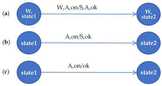
Figure 3.
Full description of the action as a transition in the automaton, and its simplifications. W: automaton (server), S: target automaton of a message, A: agent, statei: state values of the server W, on: service of W invoked by the incoming message, ok: service of the server S invoked by the outgoing message.
This is an action in server W, so its name can be omitted in states (W, state1) and (W, state2). In the action agent A calls the on service on server W. This action sends the agent message to server S, calling its service ok. The states state1 and state2 refer to the same server, and it is the same server to which the input message is directed, in this case W. We can therefore replace the states that are pairs, such as (W, state1) with the state values as state1. We can also omit the server in the input message (server, agent, service), leaving a pair (agent, service), for example (A, on). The output message is of the same agent as the input one, so we can omit the agent in the output message, which shortens it to a pair (server, service), such as (S, ok). However, the server to which the output message is directed cannot be omitted in the general case. In exceptional cases, when the server in the output message is known, only the service may be left. However, this only applies to specific cases where it is “natural” to route the message to a specific server, for example, to route an ok reply to the server, which is the only source of the input message.
5. Verification
The verification in the IMDS formalism consists in reviewing the configuration reachability graph. Verification in CTL temporal logic consists in finding a fixed point of a specific functional, which exceeds the scope of this article and can be found in [36]. The verification algorithm works as if it browses all possible system execution sequences simultaneously (and not one by one, because it is impossible), looking for a configuration with specific characteristics. The Dedan verifier uses the CBS algorithm (checking by spheres [37]) to find the following system properties: deadlock, inevitable termination, and possible termination. For this purpose, for each configuration T in the reachability graph, the logical value of the atomic formulas is determined:
- DT(s), s∈S — for a server s, the formula is true in every configuration T, for which there is a message of some agent and directed to server s, i.e., ∃p∈P,p = (a,s′,r) p∈T ∧ s = s′,
- ET(s), s∈S — for a server s, the formula is true in every configuration T, for which at least one action is enabled on the server s, i.e., ∃λ∈Λ,λ = (((a,s′,r),(s′,v)),((a,s″,r″),(s′,v′))) (a,s′,r)∈T ∧ (s′,v)∈T ∧ s = s′.
A server s deadlock is defined as a configuration in which at least one message is waiting in the server, but in the present and future of this server (in the reachability graph in the T configuration and all configurations reachable from T), no action is allowed on the server s. It is the temporal formula in CTL logic: AG (DT(s) ∧ −ET(s)). The AG operator means “always on all paths”, obviously starting in the T configuration. In the system, we always ask about the possibility of a deadlock, so the complete formula is EF AG (DT(s) ∧ −ET(s)). The EF operator means “there is such a path”. The whole sentence can therefore be read as “there is a configuration on each path where a message waits at a server, but no action can be performed in the present R and the future of this server”. Since the truth of the DT(s) and ET(s) formulas can be determined statically, it is possible to automatically test the occurrence of deadlocks of a given server without knowing the temporal formulas, so they are hidden in the Dedan verifier. We can also ask for a deadlock in a set of servers, and then the formula will be Sx = {s1,s2,…}⊂S: EF AG (DT(s1) ∧ −ET(s1) ∧ DT(s2) ∧ −ET(s2) ∧ …). Such a formula is also automatically verified by the Dedan program after selecting a set of servers (in particular, all servers can be appointed).
For each configuration T, the truth of the atomic logical formulas is also determined:
- DT(a), a∈A—for an agent a, the formula is true in every configuration T, in which a message of the agent a is present, i.e., ∃p∈P,p = (a′,s,r) p∈T ∧ a = a′, that is, the agent did not terminate.
- ET(a), a∈A — for an agent a, the formula is true in every configuration T, in which at least one action is enabled with the participation of the agent a, i.e., ∃λ∈Λ,λ = (((a′,s,r),(s,v)),((a′,s′,r′),(s,v′))) (a′,s,r)∈T ∧ (s,v)∈T ∧ a = a′.
- FT(a), a∈A—for an agent a, the formula is true in every configuration T in which no message of the agent a is present, i.e., ∀m∈T,m = (a′,s,r) a ≠ a′.
We define an agent deadlock as a configuration in which agent a message occurs, but in the present and the future of this agent (in the reachability graph in configuration T and all configurations reachable from R), no action is allowed with the agent’s message on input. Because we ask for the possibility of a deadlock, it is written in a temporal formula in the logic of CTL: EF AG (DT(a) ∧ −ET(a)). Similarly to servers, we can ask about common deadlocks of a set of agents, and then the formula will have the form Ax = {a1,a2,…}⊂A: EF AG (DT(a1) ∧ −ET(a1) ∧ DT(a2) ∍ −ET(a2) ∍ …) and even we can ask about all agents.
Termination is a situation in which the agent has performed a terminating action, so the inevitability of termination is the occurrence of a configuration on each path in the reachability graph that does not contain the agent’s message, which is expressed by the formula AF (FT(a)). The AF operator means “eventually on every path”.
Possible termination, in turn, is a situation where a configuration without an agent message occurs on some path, as expressed by the formula EF (FT(a)).
It should be emphasized that the TempoRG algorithm works according to the principle of strong fairness (compassion) [10]. Compassion means that for any cycle in the reachability graph, if it is possible to escape from this cycle, then the agent must escape from it after many possible executions of the cycle. This feature ensures that the system does not get stuck in any “starvation” of any of its servers if it can perform the specified action. The same goes for agents. Lack of compassion can lead to the detection of non-existent deadlocks or an indication of a false non-termination [10].
Thus, verification consists in indicating the servers/agents and the feature we want to check. For example, the inevitable termination of agents that terminate after experiencing certain desired events in the system.
5.1. Modeling System Elements
The primary task is to isolate relatively independent elements in the system that cooperate by transmitting widely understood signals. These signals are either applying to a specific point Vcc (Voltage common collector) or ground, or acting on a specific contact. It does not make any difference whether the contact is influenced by a human (button/switch), or it is a contact controlled by the relay coil. Therefore, the basic modeled elements will be the contact and the coil. Bringing to a specific point of Vcc or ground will be hereinafter referred to as a positive signal (or giving a signal or simply a signal), and withdrawal of Vcc/ground as a negative signal (or withdrawing a signal or simply no signal), and acting on the contact as causing a short circuit (closing) or an opening. The agent giving/withdrawing the signal or the closing/opening must return to the element from which it came to be able to propagate the signal to other elements.
The excitation of the relay coil activates the agent, which causes the closing/opening of the contacts of this relay. De-energizing the relay coil causes the opposite action (the agent is also triggered, causing the opening/closing of the contacts). The agent providing/withdrawing the signal returns to the element it came from, and the coil “triggers” its own controlling relay contacts. The coil acts as an AND gate as it requires signals from both sides (Vcc and ground) to wake up. As the controlled contacts are mechanical, it is assumed that they can be closed/opened in any order. The relays used in the actual system switch the contacts in such a way that between the normally open (NO) contacts and the normally closed (NC) contacts there is a state in which all contacts are open simultaneously. This is a standard function called rigid contact guidance, implemented in relays used in safety-related systems [38], including railway [39,40,41], and ensuring the possibility of considering a limited number of states that a relay may be in, including during a fault. Simultaneous contact operation is not modeled because the mathematical model is interleaved, but Manna and Pnueli proved that interleaved semantics (first and then second or vice versa) is equivalent to the behavior of a coincidence circuit [42].
The research assumes one-way propagation of signals (from Vcc/ground to the elements, then to the next elements, etc.). In this case, the contact acts as an AND gate; that is, the input signal and the short-circuit must work for the signal to be propagated to the output. The output signal—Vcc or ground propagation—can drive multiple elements, which we assume is at zero time so that this signal can be sequentially sent to these elements in an arbitrary order. We assume that the agent that triggers the AND gate (which gives the input signal or causes the short circuit) propagates the output signal to the output. The same happens in the case of signal withdrawal or opening. A particular version of the contact is one that outputs the signal as one of many sources. In this case, we limit the number of output items to one. The last type of element is a connection that works like an OR gate, i.e., when a signal is sent to any input, it sends a signal to all outputs, and the withdrawal of the signal from all inputs causes the signal to be withdrawn from the outputs.
The connection diagrams of the modeled elements are shown in Figure 4. This is an overview drawing showing the different types of elements and their surroundings. They are: (a) coil, (b) contact, (c) contact with the connection of signals at the output, (d) connection. The coil (a) requires two signals to be given: Vcc (in the figure from the top) and ground (from the bottom). Contact (b) has two inputs: a signal source and a short-circuit source. The contact with a connection on the output (c) is specific because the model must consider which input caused the signal to be passed to the output S, and the agent must return to this input.
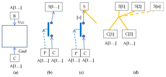
Figure 4.
Connection diagrams of selected logical elements: (a) coil, (b) contact/switch being the only source of signal, but potentially for many elements at the output (c) contact/switch not being the only source of signal (with number x), for one element at the output (d) galvanic connection. A [1…] is a vector of all agents (any agent can give a signal). S [1…] is a vector of elements on output.
The connection (d) is made for the two signal sources, and it is an OR-type gate. There are two signal sources at the input, and any number of them may be output. The combination of more sources can be realized in series or as a separate model. An additional technical element is an intermediary element used where the same element is the source of both the signal and the short-circuit. It can be treated as connection with 1 input and 1 output. In the diagram, coils are marked with rectangles, relay contacts with ovals of the same color as the coil, contacts controlled “from the environment” by red diamonds, connections by yellow clusters of bold segments, and intermediary elements as elongated purple rectangles.
The logical model of the system is presented in Figure 5. The ENV environment has been added to the elements described above, which is the source of power and ground, and closes and opens the switch contacts. In fact, these contacts belong to the relays of the circuit covering the circuit under consideration, which in this case, is irrelevant. Straight arrows indicate Vcc supply, dotted arrows—ground supply, and dashed arrows—contact operation. The types of elements are: O1—contact for controlling 1 element, O2—contact for controlling 2 elements, O1_1—contact for controlling 1 element for which it is the first source, O1_2—contact for controlling 1 element for which it is the second source, ENV—environment whose design will be discussed further, OR21—connection of two wires which is a source for 1 element, OR22—connection of two wires which is a source for 2 elements. Three primary agents are used in the model, with their numbers 1-E (the agent from the ENV automaton supplying Vcc, ground and closing/opening contacts operated from outside the circuit), 2-W relay agent, 3-Z relay agent.
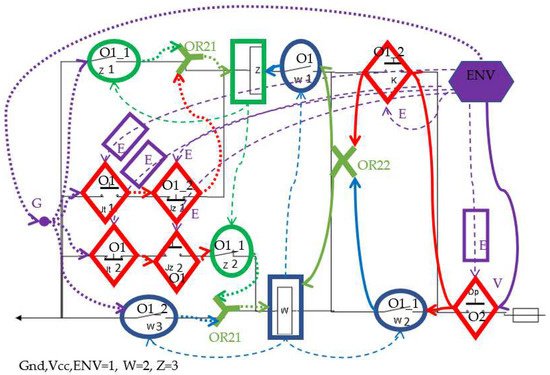
Figure 5.
Identification of logical elements on the schematic diagram of the line block, and marking their types.
Figure 6 shows the contact model, which in this case, has two outputs. One of the agents A[i] closes the contact or gives a signal from the input. The parts of the model outlined with dashed red ovals are stable states: on the left, the state does not provide a signal to the output (these are three states as the contact corresponds to the AND gate, i.e., it requires both a short-circuit and a signal from the input). The initial state—open and no input signal—is indicated by a solid triangle. In the case of an initially closed contact, the initial state is indicated by a hatched triangle. The paths leading from one red oval to the other are the feeding or withdrawing of the signal successively at individual outputs. The colors of the message mean: green—message from the input, red—sending a signal to the output element, blue—message from the output element (agent returning from the output element), violet—confirmation message for the input element (agent returns to the input element). An action in box—ignored messages in steady states, for example, withdrawing a signal that has already been withdrawn, or giving a signal that has already been applied once. The m signal represents voltage or ground (m1—giving a signal, m0—signal withdrawal). Contact closing is on, and the opening is of. The contact, which is not the only source of the signal, is not shown because it differs only in that the signal m1/m0 is indexed by the source number (m1 [1], m1 [2], m0 [1], m0 [2]).
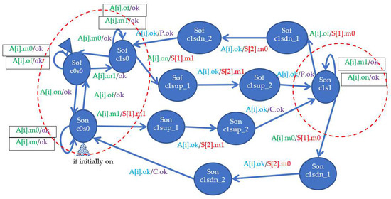
Figure 6.
Model of connector/switch. P and C.
The coil model (Figure 7) is similar, but differs in that it receives two types of signals: v and g (Vcc and ground), and has its own agent P, which is inactive in a steady state (idl message). The g signal comes from the C input, and the v signal from the B input. Stable states in which the winding is de-energized are shown in the red oval on the left (the AND function is performed). Giving both the signal v and g causes the coil to be energized, and then agent P successively closes the contacts—in any order—and returns to inactivity with the message idl. These are paths between stable states. The contacts can also be normally closed, as shown by the alternative actions for the S2 contact surrounded by a dashed line. It was assumed that the relay has two normally open contacts, or one normally open contact (S1) and the other normally closed (S2)—actions with a dashed border. As before, a solid line surrounds actions that ignore the signal that has already been given, or its withdrawal when it has already been withdrawn.
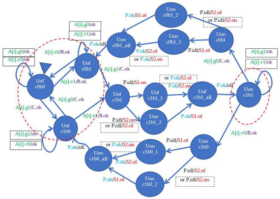
Figure 7.
Coil model.
The model of the galvanic connection is shown in Figure 8. It is a connection of two wires, having two elements at the output.
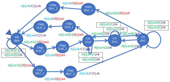
Figure 8.
Galvanic connection model.
The system model uses the following types of elements: contacts controlled from the outside Jt1:O1, Jt2:O1, Jz1:O1_2 (it is the second source for OR21 on the ground input Z), Jz2:O1, Dp:O2 (gives a signal to two elements w2 and K), K:O1_2 (it is the second source for OR22), connections OR21 (used twice) and OR22, and relays: W in NO contacts w1:O1, w2:O1_1 (first source for OR22), w3:O1_2 (second source for OR21) and Z with NO contact z1:O1_1 (first source for OR21 at ground input Z) and NC z2:O1_1 (first source for OR21 at ground input W). Additionally, we add the letter B for some elements on the Vcc side, for example, OR22B, and the letter C for the ground side.
Attached to the layout model is an environment model with its own agent (number 1). It is an automaton that consecutively feeds ground to the system (to elements z1, Jt1, Jt2, w3), Vcc to K, and then it closes the Dp contact, closes K, opens Jt1 and closes Jt2 (in arbitrary order), opens K, closes Jz1 and opens Jz2 (in arbitrary order), closes Jt1 and opens Jt2 (in arbitrary order), opens Jz1 and closes Jz2 (in arbitrary order). It is an automaton with a boring structure that sends signals and closes/opens specific contacts in the required order. The last step is sending the environment agent to the observer’s automaton, about which later.
The observer automaton (Figure 9) tracks the correct end of the system operation. Each of the relay coils has an additional agent that starts at the moment of excitation and informs the observer’s automaton about this fact. If such messages are received from both coils, the environment agent that arrives at the observer after all operations in the environment automaton are completed, terminates.

Figure 9.
Observer model.
5.2. The Course of the Verification
5.2.1. Basic Checking
The model consists of many elements, connected in various ways. Therefore, it is not difficult to make a mistake, for example, giving a signal instead of withdrawing it, or confirming it to the wrong source. Finding such a situation is quite simple as it typically leads to a deadlock. A deadlock is defined in IMDS as a server state in which a message is waiting that will never be handled. Some of such situations are harmless, in our case the relay agents closing/opening the contacts due to the excitation/de-excitation of the relay coil should wait inactive at the end of the system operation. This is a “technical” deadlock situation because the current message of such an agent is “idle” and this message will not be handled due to termination of the system operation sequence. The model is considered correct as soon as the relay agents go into a deadlock and the rest either terminate or fall into an actual (unexpected) deadlock signifying a failure in the circuit design.
5.2.2. Unexpected Error
The basic test is to check whether, with all the elements working properly, and with the correct sequence of shortings/openings of contacts controlled from the outside, the system reaches the designated final state. In our case, this is the excitation of both relay coils. In typical engineering practice, proper operation of a system is demonstrated by manual analysis, which is like running a finger across a system scheme and pinpointing the excitation and short-circuit sequences. However, this cannot be considered proof of correctness as it is impossible to demonstrate the inevitability of proper termination manually. Model checking verifies all possible behavioral paths of the system simultaneously, which leads to proof of correctness. It should be distinguished here that the formal evidence prepared by the verifier concerns all behaviors, and the witness obtained as a result shows one, exemplary path of the system behavior. Other paths can be obtained through layout simulation, available in the Dedan verification environment.
Verification of the system after removing modeling defects should lead to the correct operation of the system, i.e., pick up of both relays (and then drop away, which we omit in the study, but we could test). However, an unexpected deadlock occurs during the test; the final sequence of the counterexample is shown in Figure 10 (placed horizontally to save space). It is the “lifeline” of one of the elements—the OR22B connection from Figure 5. This lifeline was cut from the parallel lines of other elements, which can be seen further in the example of the correct verification result. The lifeline begins with the element name and initial state, and a zigzag line covers the compressed part of the diagram. This is followed by the states of the element (server) on a blue background and messages on a yellow background. The names of the agents sending the messages are shown on a light-yellow background. A thick gray line separates the sequence of changes from the final state and final message. This final message is unhandled, so it means the agent and the OR22B element deadlock at the same time.

Figure 10.
Action sequence in OR22B element, leading to error (unhandled message).
We can see how the OR22B connection receives the signal b1 [1] (the equivalent of supplying Vcc from the first input), but before it propagates it to its output elements, it receives the signal b0 [2], i.e., withdrawing the power through the second input. It will not be “serviced” because the connection is not yet in a stable state and deals with the propagation of the signal to the output elements. Note that this is a sequence of closing/opening by the relay of its contacts, which may mean that they will not effectively close when the voltage necessary for excitation is withdrawn too early. Consultations with a specialist have shown that in the system presented in this way, such a situation may actually occur. The protection consists in adding a delay circuit (not visible in the circuit diagram), causing the K switch to keep the W relay energized long enough for it to have enough time to maintain its power supply for contact w2. This could be modeled in a real-time model, but instead, we introduced an additional dependency: the switch K withdraws the power to the relay W only after the ENV receives the information about the completion of the contact switching.
We describe this situation in detail, because this situation shows an important feature of verification in the IMDS formalism, which retains in the verified model information about component processes and allows to distinguish expected deadlocks from those that show system design errors. This confirms the considerable “sensitivity” of the method to subtle errors—in this case, the need to protect against signal changes in unstable states of the system.
After modifying the system by introducing the above-described change, a similar error occurred on the ground side in the Z relay. It turns out that there is adequate protection here, but it was obtained by a different method—through the physics of the controlled physical system. It turns out that the ground supply to the Z relay is “watched over” by the train itself, which cannot travel so fast that after applying ground to the Z coil, the ground supply through the Jz1 contact immediately stops. However, when designing the system, proper vigilance should be exercised, if we limit the speed range of trains at which the control system works correctly.
5.2.3. Correct Sequence
Getting rid of the instability errors described in the previous section should result in a good circuit where the circuit inevitably achieves its goal of energizing both relays. This test checks for the inevitable termination of the AEnv agent, which terminates it after receiving a message that both relays have worked. The two observer agents, AobsW and AobsZ, are used to transmit these messages. The result of the test in the Dedan program is shown in Figure 11.
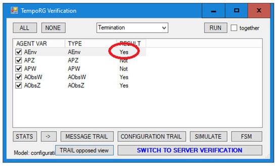
Figure 11.
Verifier window showing Aenv agent termination.
Figure 12 shows the initial witness sequence, with the enlarging of the start of the environment agent Aenv (red rectangle), and Figure 13 shows the final fragment containing the termination of this agent (green rectangle).
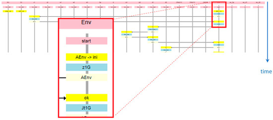
Figure 12.
The witness of correct termination—the initial fragment.
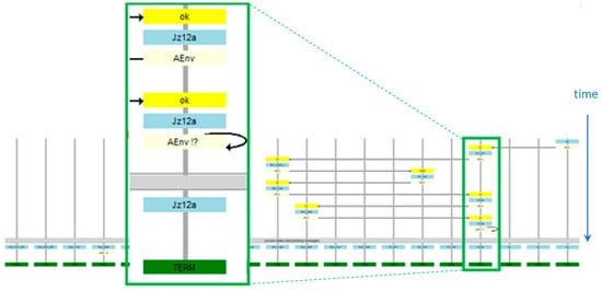
Figure 13.
The witness of correct termination—the final fragment.
5.2.4. Element Failure—Short Circuit between Input and Output
A damaged element behaves differently than a correct one, therefore it requires special modeling. Figure 14 shows a contact whose input and output are closed, so it does not react to opening attempts: it is permanently closed. Actions that disappear are marked with a dashed line and a crossed-out label, and actions replacing them are marked in red with a label in a red box.
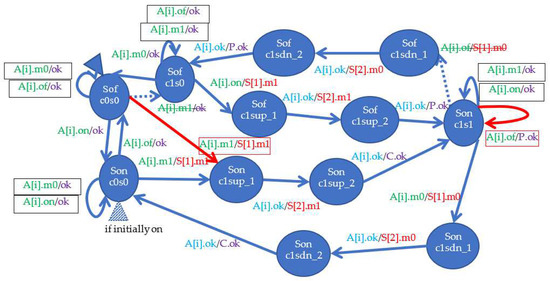
Figure 14.
Damaged element—a permanent short-circuit between input and contact output.
The fault was defined in switch K. Surprisingly, the system still behaves correctly despite the constant short-circuit of the switch. After consulting a specialist, it turns out that the K switch does not perform a logical function in the system, but only has a protective function.
5.2.5. Damage to the Element—Permanent Opening
A permanent opening of the contact should lead to a safe situation, i.e., none of the coils should be excited. The damage model is quite simple, shown in Figure 15. The model of the damaged element was used for contact z2.
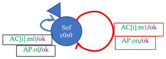
Figure 15.
Damaged element—permanent opening of the input with the contact output.
The verification shows that the termination of the environment agent (after energizing both coils) is not inevitable, but in this case, it should rather be checked whether termination is possible. The security condition says that termination should not be possible. This is indeed the case, as shown in the final fragment of the environment agent that gets stuck in a deadlock (Figure 16).
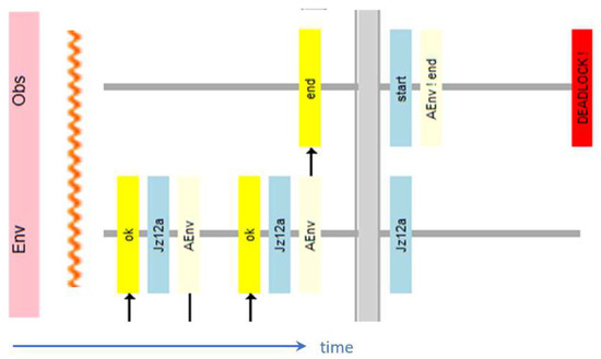
Figure 16.
Counter-example for the study of freedom from system deadlock—final fragment.
The Env agent models the environment, so it sends signals to the system regardless of whether it is working correctly or not. However, this agent terminates when it gives all signals to the system, and additionally receives information that both relays have worked. This is illustrated in Figure 9: agent Env terminates only from the all state, which is achieved after both observers AObsW and AObsZ report operation of relays. The analysis of the counterexample shows that the coil W receives the power signal b1, then its recall b0, and never receives the ground signal c1. Likewise, coil Z receives a ground signal but does not receive a power signal. Therefore, none of the relays can work, which causes the Env agent to remain in the start state with the end message, so this message will never be handled, which is a deadlock, so the agent will not terminate.
5.2.6. Incorrect Sequence of Actions Controlled from the Environment
We can think of all sorts of incorrect sequences, but the best test is the behavior of the system in the case of a train going in the opposite direction: it closes the Dp contact, it closes K, it closes Jz1 and opens Jz2 (in arbitrary order), opens K, opens Jt1 and closes Jt2 (in arbitrary order), opens Jz1 and closes Jz2 (in arbitrary order), closes Jt1 and opens Jt2 (in arbitrary order). The behavior of the model is similar to the previous point, only the environment agent gets stuck in deadlock in a different state.
6. Conclusions and Further Work
The experiments were successful in confirming the correct functioning of the line block fragment, and as part of this study, the identification of time-sensitive fragments. The proof of the inevitability of the correct termination of the work by the system with the correct sequence of input signals was made. Example possible failures were also modeled, and it was shown that the system behaves safely in each of them, i.e., it does not generate a sequence of output signals that would allow two trains to enter the same track section.
The research methodology consists of:
- Specification of circuit elements using a graphical form of distributed automata DA3. In a case of safety checking in the occurrence of faults, specification of faulty elements in the same fashion.
- Specification of observer agents that investigate the required/unwanted changes of states of individual elements.
- The proving of the correctness of the system is done by the inevitability of reaching their termination by the specified agents. This feature is checked automatically. Termination is partial in this case (which is also a rare feature among verifiers) because other agents may be in a “technical” deadlock state.
- Checking inevitable termination in the case of correct termination (required property), or possible termination in the case of safety checking of a faulty circuit or faulty input sequence (unwanted property). Finding partial deadlocks, causing the lack of termination, discovers malfunctioning elements or subsystems while the rest of the circuit can work properly.
Note that even very subtle situations are detected where correct operation depends on specific input signal durations. Note that this is done in a timeless model. The designer must demonstrate that the input signals last long enough and modify the model to overcome the effect of too short times.
Comparing to other verification environments, the novelty and research contribution of our approach lies in the following:
- Graphical modeling of systems is rare. Among the works on relay systems, only [12,14] use UML state diagrams, and [16] schematic diagrams. Both of these approaches, however, require translation into a Kripke structure, which may subtly influence the semantics of the model. The remaining works cited use little readable switch tables [15] or text input in the form of complex formulas or a domain-specific language or B method [17]. In our approach, the design of element models takes place directly in the intuitive form of graphical distributed automata, fully compatible with the algebraic model subject to verification. The semantics of both specification methods (graphical and algebraic) are identical, so the specification does not require translation into the verifier’s input data. The same applies to the approaches based on the Uppaal specification [7,18].
- The investigated properties of systems are typically specified using temporal formulas (or ProB verifier formulas [17]). As industrial practice shows, for the vast majority of designers, this is an entry threshold that is (subjectively) difficult to overcome. And it is rarely possible to invite a researcher familiar with temporal logic to permanent cooperation in the checking of systems. Some of the cited works replace temporal formulas with typical, predefined properties that are internally replaced by sentences in temporal logic [15,16]. Instead of temporal formulas examining individual characteristics, we introduce observer automata, which can be easily designed by the user. These automata report that the system has achieved certain states, as shown in this article. A similar approach using Uppaal observers is only shown in [18]. The observer automaton achieves the “deliberate” deadlock state in the event of a system malfunction (primarily in the case of security testing).
- Our original idea is to introduce damaged elements to the library of models. Replacing an element (or several elements) with a damaged one, and subjecting the system to an incorrect sequence of external events, allows for checking whether the system will behave safely in such circumstances. The system should not reach a supported end state in such a situation, but should protect the managed system from a catastrophe, for example, by letting two trains onto the same track. If the system does not behave safely, then again, the possibility of simulating a counterexample on component automata would make it possible to find the reason for this behavior. Demonstrating the safety of the system even in the event of damage may be necessary in the process of its certification.
- A feature that is automatically detected by all verifiers is a total deadlock. Some verifiers detect partial deadlocks, but this requires a specific structure of the system under investigation, or the user specifies an appropriate temporal formula. Our verification method is specific in that it automatically detects partial deadlocks where some components are stuck while others are still working correctly. This allows a broader class of errors to be detected.
- The fairness aspect of the verifier is significant but often overlooked. Most of the verifiers available do not provide fairness at all, or only weak fairness. Among the verifiers used in the cited articles, Spin and Uppaal do not provide strong fairness. NuSMV ensures fairness as long as the user specifies special formulas for each expected fair divergence in the operation of individual automata. The work [10] shows how the lack of strong justice (compassion) can lead to the detection of a non-existent deadlock. The verification algorithm we use as well as the one used in ProB [17] provide strong fairness.
The manual design of system elements, which differ slightly in structure, is quite burdensome. We plan to introduce a library of parameterized elements; in our opinion, only a few of them are enough. This also applies to the library of damaged items.
After verifying that the specified component failure leads to a safe state, the state of all system components can be registered. In this way, it is possible to classify what condition of the damaged system as suggested by the damage, i.e., the creation of a diagnostic tool.
Many system features can be checked in the verification without time, but we also provide testing with real-time constraints.
Author Contributions
Conceptualization, J.K., W.B.D., W.G. and A.K.; methodology, J.K., W.B.D. and W.G.; software, W.B.D.; validation, J.K, W.B.D., W.G. and A.K.; formal analysis, J.K., W.B.D. and W.G.; investigation, J.K. and W.B.D.; resources, J.K and W.G.; data curation, J.K.; writing—original draft preparation, J.K. and W.B.D.; writing—review and editing, J.K., W.B.D. and W.G.; visualization, W.B.D.; supervision, W.B.D. and A.K.; project administration, A.K.; funding acquisition, A.K. All authors have read and agreed to the published version of the manuscript.
Funding
Research was funded by Warsaw University of Technology within the Excellence Initiative: Research University (IDUB) program.
Data Availability Statement
Not applicable.
Conflicts of Interest
The authors declare no conflict of interest.
References
- Eap. Jednoodstępowa (półsamoczynna) Blokada Liniowa Typu Eap-94 [Single-section (semi-automatic) Line Block Type Eap-94]. 2016. Available online: http://www.pphu-mgrot.pl/download/pdf/DTREap-94.pdf (accessed on 28 September 2022). (In Polish).
- IEC62425:2007; Railway Applications—Communication, Signalling and Processing Systems—Safety Related Electronic Systems for Signalling. International Electrotechnical Commission: Geneva, Switzerland, 2007. Available online: https://webstore.iec.ch/publication/7001 (accessed on 28 September 2022).
- EN50129:2018; Railway Applications—Communication, Signalling and Processing Systems—Safety-Related Electronic Systems for Signalling. The European Committee for Standardization (CEN): Brussels, Belgium, 2018. Available online: https://standards.iteh.ai/catalog/standards/clc/f6548cc3-5885-43aa-8654-9e71383b892e/en-50129-2018 (accessed on 28 September 2022).
- EN50126-1:2017; Railway Applications—The Specification and Demonstration of Reliability, Availability, Maintainability and Safety (RAMS)—Part 1: Generic RAMS Process. The European Committee for Standardization (CEN): Brussels, Belgium, 2017. Available online: https://standards.iteh.ai/catalog/standards/clc/e5456892-eb2c-437e-8c4b-91c08007f0b4/en-50126-1-2017 (accessed on 28 September 2022).
- EN50126-2:2017; Railway Applications—The Specification and Demonstration of Reliability, Availability, Maintainability and Safety (RAMS)—Part 2: Systems Approach to Safety. The European Committee for Standardization (CEN): Brussels, Belgium, 2017. Available online: https://standards.iteh.ai/catalog/standards/clc/67bf2fa9-46a2-4460-a907-91b2ac91d7fc/en-50126-2-2017 (accessed on 28 September 2022).
- Li, J. SIL Implementation on Safety Functions in Mass Transit System. Int. J. Math. Eng. Manag. Sci. 2018, 3, 258–270. [Google Scholar] [CrossRef]
- Daskaya, I.; Huhn, M.; Milius, S. Formal Safety Analysis in Industrial Practice. In FMICS 2011: Formal Methods for Industrial Critical Systems; Salaün, G., Schätz, B., Eds.; Springer: Berlin/Heidelberg, Germany, 2011; pp. 68–84. [Google Scholar] [CrossRef]
- Daszczuk, W.B. Specification and Verification in Integrated Model of Distributed Systems (IMDS). Computers 2018, 7, 65. [Google Scholar] [CrossRef]
- Daszczuk, W.B. Graphic modeling in Distributed Autonomous and Asynchronous Automata (DA3). Softw. Syst. Model. 2021, 20, 363–398. [Google Scholar] [CrossRef]
- Daszczuk, W.B. Fairness in Temporal Verification of Distributed Systems. In DepCoS-RELCOMEX 2018: Contemporary Complex Systems and Their Dependability; Zamojski, W., Mazurkiewicz, J., Sugier, J., Walkowiak, T., Kacprzyk, J., Eds.; Springer International Publishing: Cham, Switzerland, 2019; Volume 761, pp. 135–150. [Google Scholar] [CrossRef]
- Ferrari, A.; Magnani, G.; Grasso, D.; Fantechi, A. Model Checking Interlocking Control Tables. In FORMS/FORMAT 2010; Schnieder, E., Tarnai, G., Eds.; Springer: Berlin/Heidelberg, Germany, 2011; pp. 107–115. [Google Scholar] [CrossRef]
- Fantechi, A. Distributing the Challenge of Model Checking Interlocking Control Tables. In ISoLA 2012: Leveraging Applications of Formal Methods, Verification and Validation. Applications and Case Studies; Margaria, T., Steffen, B., Eds.; Springer: Berlin/Heidelberg, Germany, 2012; pp. 276–289. [Google Scholar] [CrossRef]
- Haxthausen, A.E.; Le Bliguet, M.; Kjær, A.A. Modelling and Verification of Relay Interlocking Systems. In Monterey Workshop 2008: Foundations of Computer Software. Future Trends and Techniques for Development; Choppy, C., Sokolsky, O., Eds.; Springer: Berlin/Heidelberg, Germany, 2010; pp. 141–153. [Google Scholar] [CrossRef]
- Haxthausen, A.E.; Peleska, J.; Pinger, R. Applied Bounded Model Checking for Interlocking System Designs. In SEFM 2013: Software Engineering and Formal Methods; Counsell, S., Núñez, M., Eds.; Springer International Publishing: Cham, Switzerland, 2014; Volume 8368, pp. 205–220. [Google Scholar] [CrossRef]
- Haxthausen, A.E.; Østergaard, P.H. On the Use of Static Checking in the Verification of Interlocking Systems. In ISoLA 2016: Leveraging Applications of Formal Methods, Verification and Validation: Discussion, Dissemination, Applications; Margaria, T., Steffen, B., Eds.; Springer International Publishing: Cham, Switzerland, 2016; pp. 266–278. [Google Scholar] [CrossRef]
- Amendola, A.; Becchi, A.; Cavada, R.; Cimatti, A.; Ferrando, A.; Pilati, L.; Scaglione, G.; Tacchella, A.; Zamboni, M. NORMA: A tool for the analysis of Relay-based Railway Interlocking Systems. In TACAS 2022: Tools and Algorithms for the Construction and Analysis of Systems; Fisman, D., Rosu, G., Eds.; Springer: Cham, Switzerland, 2022; pp. 125–142. [Google Scholar] [CrossRef]
- de Almeida Pereira, D.I.; Deharbe, D.; Perin, M.; Bon, P. B-Specification of Relay-Based Railway Interlocking Systems Based on the Propositional Logic of the System State Evolution. In RSSRail 2019: Reliability, Safety, and Security of Railway Systems. Modelling, Analysis, Verification, and Certification; Collart-Dutilleul, S., Lecomte, T., Romanovsky, A., Eds.; Springer: Cham, Switzerland, 2019; pp. 242–258. [Google Scholar] [CrossRef]
- Lahtine, J. Model Checking Timed Safety Instrumented Systems; Helsinki University of Technology, Department of Information and Computer Science: Helsinki, Finland, 2008; Available online: https://aaltodoc.aalto.fi/handle/123456789/874 (accessed on 28 September 2022).
- Behrmann, G.; David, A.; Larsen, K.G.; Pettersson, P.; Yi, W. Developing UPPAAL over 15 years. Softw. Pract. Exp. 2011, 41, 133–142. [Google Scholar] [CrossRef]
- Sabatier, D. Using Formal Proof and B Method at System Level for Industrial Projects. In RSSRail 2016: Reliability, Safety, and Security of Railway Systems. Modelling, Analysis, Verification, and Certification; Lecomte, T., Pinger, R., Romanovsky, A., Eds.; Springer: Cham, Switzerland, 2016; Volume 9707, pp. 20–31. [Google Scholar] [CrossRef]
- Comptier, M.; Deharbe, D.; Perez, J.M.; Mussat, L.; Pierre, T.; Sabatier, D. Safety Analysis of a CBTC System: A Rigorous Approach with Event-B. In RSSRail 2017: Reliability, Safety, and Security of Railway Systems. Modelling, Analysis, Verification, and Certification; Fantechi, A., Lecomte, T., Romanovsky, A., Eds.; Springer: Cham, Switzerland, 2017; Volume 10598, pp. 148–159. [Google Scholar] [CrossRef]
- James, P.; Moller, F.; Nguyen, H.N.; Roggenbach, M.; Schneider, S.; Treharne, H. Techniques for modelling and verifying railway interlockings. Int. J. Softw. Tools Technol. Transf. 2014, 16, 685–711. [Google Scholar] [CrossRef]
- Idani, A.; Ledru, Y.; Ait Wakrime, A.; Ben Ayed, R.; Bon, P. Towards a Tool-Based Domain Specific Approach for Railway Systems Modeling and Validation. In RSSRail 2019: Reliability, Safety, and Security of Railway Systems. Modelling, Analysis, Verification, and Certification; Collart-Dutilleul, S., Lecomte, T., Romanovsky, A., Eds.; Springer: Cham, Switzerland, 2019; Volume 11495, pp. 23–40. [Google Scholar] [CrossRef]
- Fantechi, A.; Gori, G.; Haxthausen, A.E.; Limbrée, C. Compositional Verification of Railway Interlockings: Comparison of Two Methods. In RSSRail 2022: Reliability, Safety, and Security of Railway Systems. Modelling, Analysis, Verification, and Certification; Collart-Dutilleul, S., Haxthausen, A.E., Lecomte, T., Eds.; Springer: Cham, Switzerland, 2022; Volume 13294, pp. 3–19. [Google Scholar] [CrossRef]
- Iliasov, A.; Laibinis, L.; Taylor, D.; Lopatkin, I.; Romanovsky, A. Safety Invariant Verification that Meets Engineers’ Expectations. In RSSRail 2022: Reliability, Safety, and Security of Railway Systems. Modelling, Analysis, Verification, and Certification; Collart-Dutilleul, S., Haxthausen, A.E., Lecomte, T., Eds.; Springer: Cham, Switzerland, 2022; Volume 13294, pp. 20–31. [Google Scholar] [CrossRef]
- Kamburjan, E.; Hähnle, R. Deductive Verification of Railway Operations. In RSSRail 2017: Reliability, Safety, and Security of Railway Systems. Modelling, Analysis, Verification, and Certification; Fantechi, A., Lecomte, T., Romanovsky, A., Eds.; Springer: Cham, Switzerland, 2017; Volume 10598, pp. 131–147. [Google Scholar] [CrossRef]
- Sun, P.; Collart-dutilleul, S.; Bon, P. A model pattern of railway interlocking system by Petri nets. In Proceedings of the 2015 International Conference on Models and Technologies for Intelligent Transportation Systems (MT-ITS), Budapest, Hungary, 3–5 June 2015; pp. 442–449. [Google Scholar] [CrossRef]
- Carrasquel, J.C.; Morales, A.; Villapol, M.E. Prosega/CPN: An extension of CPN Tools for Automata-based Analysis and System Verification. Proc. Inst. Syst. Program. RAS 2018, 30, 107–128. [Google Scholar] [CrossRef] [PubMed]
- Parillaud, C.; Fonteneau, Y.; Belmonte, F. Interlocking Formal Verification at Alstom Signalling. In RSSRail 2019: Reliability, Safety, and Security of Railway Systems. Modelling, Analysis, Verification, and Certification; Collart-Dutilleul, S., Lecomte, T., Romanovsky, A., Eds.; Springer: Cham, Switzerland, 2019; Volume 11495, pp. 215–225. [Google Scholar] [CrossRef]
- Han, X.; Tang, T.; Lv, J.; Wang, H. Failure Analysis of Chinese Train Control System Level 3 Based on Model Checking. In RSSRail 2016: Reliability, Safety, and Security of Railway Systems. Modelling, Analysis, Verification, and Certification; Lecomte, T., Pinge, R., Romanovsky, A., Eds.; Springer: Cham, Switzerland, 2016; Volume 9707, pp. 95–105. [Google Scholar] [CrossRef]
- Limbrée, C.; Cappart, Q.; Pecheur, C.; Tonetta, S. Verification of Railway Interlocking—Compositional Approach with OCRA. In RSSRail 2016: Reliability, Safety, and Security of Railway Systems. Modelling, Analysis, Verification, and Certification; Lecomte, T., Pinger, R., Romanovsky, A., Eds.; Springer: Cham, Switzerland, 2016; Volume 9707, pp. 134–149. [Google Scholar] [CrossRef]
- Halchin, A.; Feliachi, A.; Singh, N.K.; Ait-Ameur, Y.; Ordioni, J. B-PERFect. Applying the PERF Approach to B Based System Developments. In RSSRail 2017: Reliability, Safety, and Security of Railway Systems. Modelling, Analysis, Verification, and Certification; Fantechi, A., Lecomte, T., Romanovsky, A., Eds.; Springer: Cham, Switzerland, 2017; Volume 10598, pp. 160–172. [Google Scholar] [CrossRef]
- Theeg, G.; Vlasenko, S. Railway Signalling & Interlocking: International Compendium, 3rd ed.; PMC Media House: Bingen am Rhein, Germany, 2019; ISBN 3962451692.
- Daszczuk, W.B. Asynchronous Specification of Production Cell Benchmark in Integrated Model of Distributed Systems. In Intelligent Methods and Big Data in Industrial Applications; Bembenik, R., Skonieczny, L., Protaziuk, G., Kryszkiewicz, M., Rybinski, H., Eds.; Springer International Publishing: Cham, Switzerland, 2019; Volume 40, pp. 115–129. [Google Scholar] [CrossRef]
- Daszczuk, W.B. 2-Vagabonds: Non-exhaustive verification algorithm. In Integrated Model of Distributed Systems (Studies in Computational Intelligence); Springer Nature: Cham, Switzerland, 2020; Volume 817, p. 256. [Google Scholar] [CrossRef]
- Baier, C.; Katoen, J.-P. Principles of Model Checking; MIT Press: Cambridge, MA, USA, 2008; ISBN 9780262026499. [Google Scholar]
- Daszczuk, W.B. Evaluation of temporal formulas based on “Checking By Spheres”. In Proceedings of the Proceedings Euromicro Symposium on Digital Systems Design, Warsaw, Poland, 4–6 September 2001; pp. 158–164. [Google Scholar] [CrossRef]
- EN50205:2002; Relays with Forcibly Guided (Mechanically Linked) Contacts. The European Committee for Standardization (CEN): Brussels, Belgium, 2002. Available online: https://standards.iteh.ai/catalog/standards/clc/f50401a3-3a46-4da5-8d81-3770892193d6/en-50205-2002 (accessed on 28 September 2022).
- UIC736:4ED-2004; Signalling Relays. International Union of Railways: Paris, France, 2004. Available online: https://www.normadoc.com/english/uic-736-2004-06.html (accessed on 28 September 2022).
- IEC62912:2015; Railway Applications—Direct Current Signalling Monostable Relays of Type N and Type C. International Electrotechnical Commission: Geneva, Switzerland, 2015. Available online: https://standards.iteh.ai/catalog/standards/iec/001b4732-c217-40bb-8798-530774bf50f5/iec-62912-2015 (accessed on 28 September 2022).
- IEC62912-2:2019; Railway Applications—Direct Current Signalling Monostable Relays—Part 2: Spring Type Relays. International Electrotechnical Commission: Geneva, Switzerland, 2019. Available online: https://standards.iteh.ai/catalog/standards/iec/7f8df920-e205-4bc4-8c49-d069fb31b4ad/iec-62912-2-2019 (accessed on 28 September 2022).
- Manna, Z.; Pnueli, A. The Temporal Logic of Reactive and Concurrent Systems; Springer: New York, NY, USA, 1992. [Google Scholar] [CrossRef]
Publisher’s Note: MDPI stays neutral with regard to jurisdictional claims in published maps and institutional affiliations. |
© 2022 by the authors. Licensee MDPI, Basel, Switzerland. This article is an open access article distributed under the terms and conditions of the Creative Commons Attribution (CC BY) license (https://creativecommons.org/licenses/by/4.0/).