Article

PID Control of a Superheated Steam Temperature System Based on Integral Gain Scheduling

1
School of Energy and Power Engineering, Nanjing Institute of Technology, Nanjing 211167, China
2
School of Energy and Environment, Southeast University, Nanjing 210096, China
3
School of Electrical Engineering, Nanjing Vocational University of Industry Technology, Nanjing 210023, China
*
Author to whom correspondence should be addressed.
Energies 2022, 15(23), 8978; https://doi.org/10.3390/en15238978
Submission received: 28 October 2022 / Revised: 23 November 2022 / Accepted: 24 November 2022 / Published: 28 November 2022
(This article belongs to the Section F1: Electrical Power System)

Abstract

:
The high-quality operation of a superheated steam temperature (SST) system is a core fact of the safety, economy, and stability of thermal power units. How to improve the control performance of an SST system under large-varying operating conditions is becoming a research hotspot. To solve this challenge, this paper proposes a proportional integral derivative (PID) control strategy based on integral gain scheduling. Based on the introduction of the SST system and classical model under typical operating conditions, the control difficulties of the SST system are analyzed theoretically. Then, a PID control strategy, based on integral gain scheduling, is introduced for the cascade control structure, and the stability of the proposed control strategy is analyzed by calculating the PID stability region. Finally, the effectiveness of the proposed method is verified under nominal and uncertain conditions, where the proposed method could obtain satisfactory tracking and disturbance rejection control performance. Simulation results show the valuable application prospects of the proposed method.

1. Introduction

With more and more random and transient new energy resources being incorporated into power grids, the safe and stable operation of power grids has been greatly challenged [1]. In order to ensure the stable operation of power grids, thermal power units undertake most of the tasks of peak-load shaving and frequency regulation. The rapid rise and fall of unit load have adverse impacts on the safety of units. As the unit load decreases, the dynamic characteristics of the unit change greatly, and the control performance declines under a low load. This situation is especially obvious in the superheated steam temperature (SST) system of such a unit [2].
An SST system is an important subsystem for thermal power units, and its control performance has a significant impact on unit safety [3]. The more the SST fluctuates, the smaller the set point of the SST is, which means that the economy of the unit decreases. In order to improve unit economy, the fluctuation of the SST needs to be controlled at a range as small as possible, so that the set point of the SST can be set to a higher value. In order to achieve the above goals, many scholars have carried out relevant research. References [4,5,6] have discussed different cascaded proportional integral derivative (PID) control strategies for an SST system, and the system’s effectiveness has been validated by simulations. References [7,8] designed active disturbance rejection control (ADRC) strategies for an SST system based on the Drosophila algorithm and the multi-objective particle swarm optimization algorithm, which can obtain better control performance than the original PID controller. In addition, Reference [9] reported an ADRC design that was tuned by quantitative rule for the SST, and the proposed tuning rule has been applied in the field. Reference [10] proposed a single-loop control strategy for the SST, based on a hybrid ADRC strategy, which was able to enhance the control performance of the SST. The structure of a closed-loop system is simpler than that of the cascade control strategy. Reference [11] proposed a control strategy based on a cascade disturbance observer and PI to improve the anti-disturbance ability of the SST, and to set the parameters through a multi-objective artificial bee colony optimization method. Nonlinear control strategies [12,13], model predictive control strategies [14,15,16], iterative learning control strategies [17], and other control strategies [18,19,20] have also been designed for the control difficulties of the SST, and the effectiveness of such control strategies has been verified by simulation. In addition, the research results of artificial intelligence have been verified in the control of the SST, and control strategies based on fuzzy control [21,22] and neural network control [23,24] have also been designed to improve the control performance of the SST. The control performance of these designed controllers has been illustrated by simulations and they are rarely used in practice.
In addition, due to the limitation of the distributed control system (DCS) platform [25], it is difficult to implement the advanced control strategy in field projects for units in service. It is also difficult to establish an accurate mathematical model of an SST system, which limits the application of a strong model control strategy [26]. PID control is the most widely used strategy in thermal power units because of its simple structure, reliable performance, and easy tuning process [27,28]. PID will continue to dominate actual control systems for a long time into the future [29,30]. However, PID controllers have limitations in the performances that are achievable [31,32,33]; this means that the control performance decreases significantly when the controlled plant operates far from the nominal condition [32]. Therefore, it is of great practical significance to study how to improve the SST control performance using PID under a wide range of variable operating conditions. With the aim of controlling the difficulties of an SST system, this paper proposes a PID control strategy based on integral-gain scheduling. The tracking and anti-disturbance performance of an SST system under various load conditions can be improved through the scheduling design of integral gain. The main contributions of this paper can be summarized as follows:
(1)
A PID scheme based on the integral-gain scheduling is proposed, which has a scheduling parameter with simple implementation.
(2)
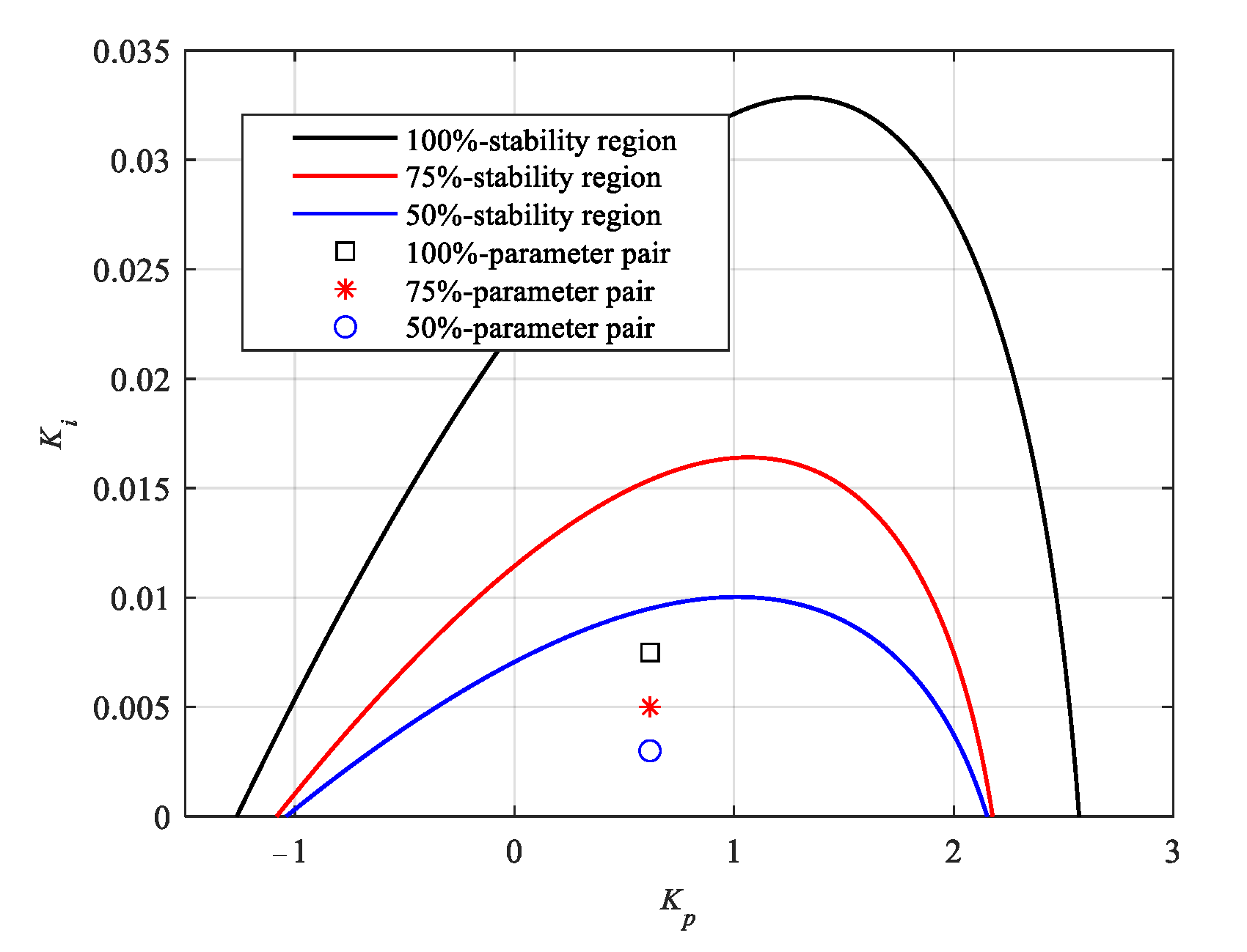
The parameters of the proposed scheme are analyzed by the calculation of the PID stability region. With reasonable tuning, all parameters of the proposed scheme can located in the stability region.
(3)
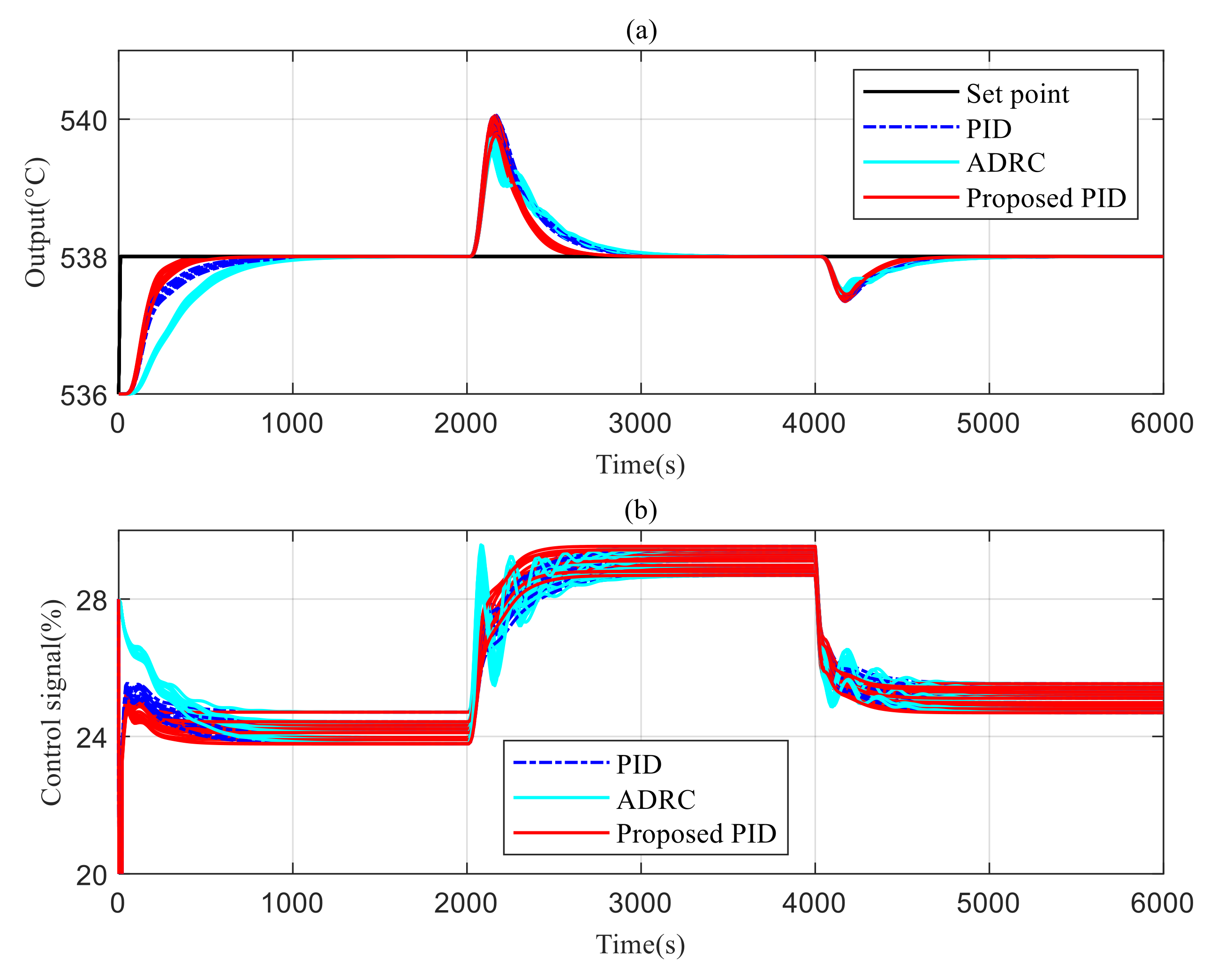
The advantages in the tracking and disturbance rejection performance of the proposed design scheme are illustrated by comparative simulations under different operating conditions. In addition, Monte Carlo experiments verify the robustness of the proposed scheme.
The rest of the paper is organized as follows: In Section 2, we introduce the basic structure and classical model of an SST system. Section 3 presents the PID design of integral gain scheduling under a cascade structure. In Section 4, the effectiveness of the proposed PID control strategy, based on integral gain scheduling, is verified by simulation under different operating conditions. Section 5 provides some conclusions.

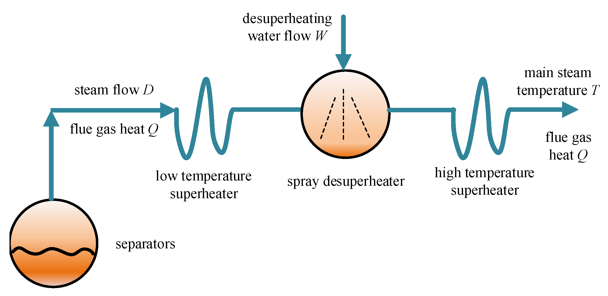
2. Problem Description

A superheated steam temperature (SST) system is an important subsystem of a thermal power unit. The structure of an SST system of a drum boiler unit is shown in Figure 1. The temperature, T, of superheated steam separated from the drum is mainly affected by the de-superheating water spray flow rate W, the steam flow rate D, and flue gas heat, Q, from the furnace. Among these factors, D and Q change with the unit load, and they are also the main disturbances of the superheated steam temperature T. The de-superheating water spray flow rate, W, is the manipulated variable of the SST system. The SST can be adjusted by controlling the magnitude of W.
Reference [33] established the SST system model of a typical multi-load supercritical 600 MW thermal power unit. The model has been widely used and has gradually become a classic model of an SST system [7]. The transfer functions of the leading segment and the inert segment of the SST under 100%, 75%, and 50% loads are shown in Table 1. It can be seen from the table that as the load decreases, the lag times of the leading segment and the inert segment increase significantly. The time constant of the inert zone under a 50% operating condition is 2.2 times higher than that under a 100% operating condition. In addition, the order of the inert zone increases at the same time. The system’s dynamic characteristics become obviously slower with the decrease in the load. The gain of the leading segment also changes greatly. It is necessary to design a control strategy of the SST system that can ensure satisfactory control performance under the whole 100–50% load range. Note that the outputs of G 1 ( s ) and G 2 ( s ) in the table are the temperature of the intermediate pipe (°C) and the main steam temperature (°C), respectively. The inputs of G 1 ( s ) and G 2 ( s ) are the valve opening (%) and the temperature of the intermediate pipe (°C), respectively. The manipulated variable and the controlled variable of the SST system are the valve opening and the main steam temperature, respectively. The disturbance variables of the SST system contain valve fluctuations ( d 1 in next section) and uncertainties of the temperature of the intermediate pipe ( d 2 in next section).

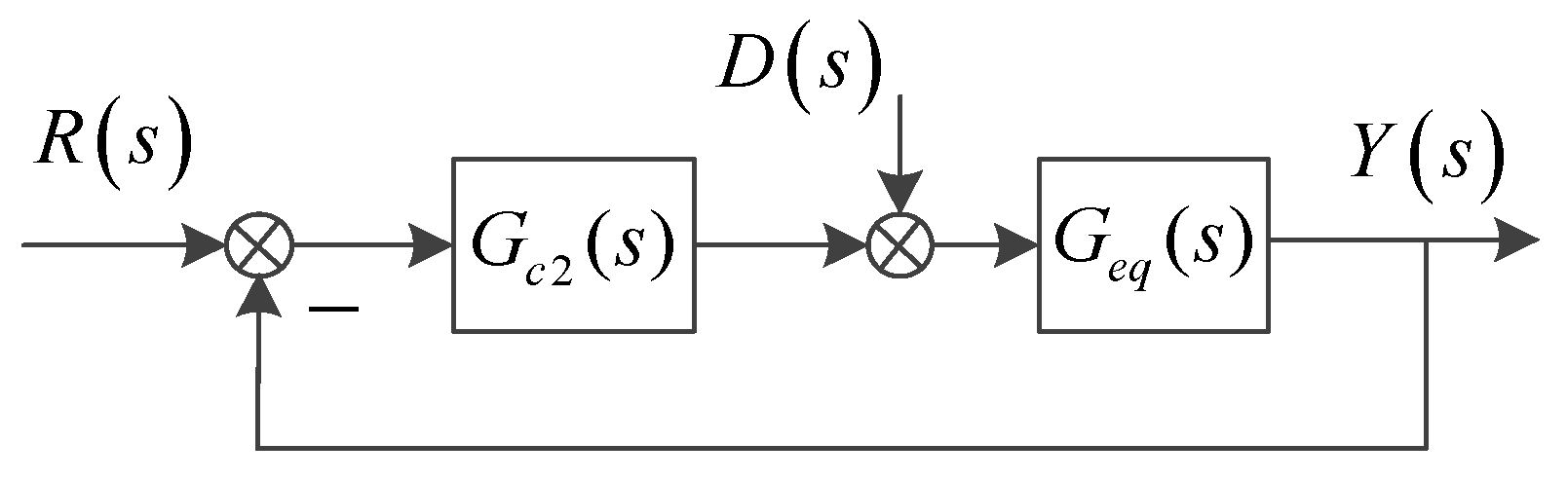
3. Control Methods Based on Integral-Gain Scheduling

The SST system includes the leading segment and the inert segment. The cascade control structure is adopted in industrial production. As shown in Figure 2, it includes two controllers, in which the output y2 of the inert area is used as the feedback of the outer loop controller, the output of the outer loop controller is used as the set point of the inner loop controller, the output y1 of the leading segment is used as the feedback of the inner loop controller, and the output of the inner loop controller acts on the valve of the de-superheating water to regulate the flow of the de-superheating water. Due to the fast response speed of the inner loop, the corresponding controller is the proportional controller. Due to the large inertia in the inert segment, the outer loop generally adopts a PID controller.
The mathematical expression of the inner loop proportional controller is as follows:
G c 1 ( s ) = k p 1
where s is the Laplace operator, k p 1 is the proportional coefficient of the proportional controller, and s and k p 1 are unit-less variables.
The mathematical expression of the outer loop PID controller is as follows:
G c 2 ( s ) = k p 2 + k i 2 s + k d 2 s
where k p 2 , k i 2 and k d 2 are the proportional coefficient, the integral-gain coefficient, and the differential-gain coefficient of the PID controller, respectively. These coefficients are all unit-less variables.
In order to improve the control performance of the SST system in the 100–50% load range, designing the control strategy of gain scheduling is an applicable and effective method for solving the strong nonlinearity of the system [1]. The more the parameters that are selected for scheduling, the more complex the engineering implementation will be. However, the PID parameters affect each other, and the unreasonable scheduling scheme will lead to a decline in control performance. Therefore, on the basis of weighing the control performance and the implementation difficulty, we selected as few scheduling parameters as possible. As shown in Table 1, the time constant of the inert zone in the SST system changed very much, which had the most obvious impact on the integral effect. To analyze the necessity of the gain scheduling, a theoretical discussion from the perspective of pole assignment is provided in Appendix A. We selected integral gain as the scheduling parameter and proposed the cascade control structure of the SST system based on the integral-gain scheduling.
The inner loop proportional controller was kept as k p 1 = 2 in order to reduce the shaking of the de-superheating water valve and to ensure the fast response speed of the inner loop. This was obtained according to the internal model control (IMC) tuning method in [34] or the following equation:
{ T i = T + τ 2 2 ( ε + τ ) k p = T i K ( ε + τ ) T d = τ 2 2 ( ε + τ ) ( 1 τ 2 T i ) k i = k p T i k d = k p T d
where T , K , and τ are the time constant, system gain, and time delay of the first-order inertia plus pure delay system, respectively, and T i and T d are the integral time constant and differential time constant, respectively. In addition, ε is the adjustable parameter. Thus, the parameters of the outer loop PID controller were adjusted. First, the inner loop closed-loop system and the inert zone system under 75% load were equivalent to the transfer function of first-order inertia plus pure delay:
G e q 1 ( s ) = 1.195 71.67 s + 1 e 118 s
The output and input of G e q 1 ( s ) are the main steam temperature (°C) and the valve opening (%).
Then, the tuning method based on the IMC was adopted, and the obtained parameters are modestly adjusted to determine the outer loop PID controller parameters:
k p 2 = 0.6171 ,   k i 2 = 0 . 0057 ,   k d 2 = 20.0000
Based on Equation (5), the integral-gain coefficient of the PID controller was optimized under different loads, and the values of the integral-gain coefficient under 100%, 75%, and 50% loads were k i 2 = 0 . 0075 , k i 2 = 0 . 005 0 , and k i 2 = 0 . 0030 , respectively, while keeping k p 2 and k d 2 unchanged.
In order to analyze the influence of the change of integral-gain coefficient on the stability of the closed-loop system, the D-partition method was used to solve the stability region of the outer loop PID controller. First, the inner loop closed-loop system and the inert zone system were equivalent to the controlled object of the outer loop, according to the following equation:
G e q ( s ) = G 2 ( s ) G 2 ( s ) × k p 1 1 + G 2 ( s ) × k p 1
The controlled object can be described by the following transfer function:
G e q ( s ) = m 0 s m + m 1 s m 1 + + m m 1 s + m m s n + n 1 s n 1 + + n n 1 s + n n = i = 0 m m i s m i j = 0 n n j s n j
where m and n are the orders of the numerator and denominator of the equivalent controlled object: m < n, m m 0 , and n 0 = 1 .
The frequency domain response of the controlled object is:
G e q ( j ω ) = r ( ω ) e i ϑ ( ω ) = a ( ω ) + j b ( ω )
where ω is the angular frequency and a ( ω ) and b ( ω ) are the real part and the imaginary part of the controlled object, respectively.
Similarly, the frequency domain response of the PID controller is determined as follows:
G c 2 ( j ω ) = k p j k i / ω + j k d ω
The PID controller and the controlled object constitute the closed-loop system, as shown in Figure 3; R ( s ) , D ( s ) , Y ( s ) are the set points of the SST, the disturbance caused by the valve, and the output of the SST system, respectively.
Based on the structure shown in Figure 3, the characteristic equation of the closed-loop system is obtained, as follows:
1 + G c ( s ) G p ( s ) = 0
That is:
ω + k p a ( ω ) ω + ( k i k d ω 2 ) b ( ω ) + ( k p b ( ω ) ω + ( k i k d ω 2 ) a ( ω ) ) j = 0
where a ( ω ) and b ( ω ) represent the characteristics of the controlled object. These variables in frequency–domain have no units.
The stability region of PID was solved by the D-partition method. Based on the principle of D-partition, the stability region boundary of the PID controller includes the singular boundary D 0 and D when ω = 0 , ω = ± , and the nonsingular boundary D ω when ω ( 0 , ) ( 0 , + ) .
(1)
ω = 0 , the singular boundary D 0 is
k i ( b ( ω ) + a ( ω ) j ) = 0
where a ( ω ) and b ( ω ) represent the characteristics of the controlled object. Therefore, the singular value boundary of the PID controller D 0 is depicted as k i = 0 .
(2)
ω = ± , the singular value boundary of the PID controller D does not exist.
(3)
ω ( 0 , ) ( 0 , + ) , the non-singular value boundary of the PID controller D ω can be solved by taking the real part and the imaginary part of Equation (11) as zero to obtain the boundary value:
{ ω + k p a ( ω ) ω + ( k i k d ω 2 ) b ( ω ) = 0 k p b ( ω ) ω + ( k i k d ω 2 ) a ( ω ) = 0
In summary, the parameter stability region of the PID controller is as follows:
{ k i = 0 ω + k p a ( ω ) ω + ( k i k d ω 2 ) b ( ω ) = 0 k p b ( ω ) ω + ( k i k d ω 2 ) a ( ω ) = 0
Combining the transfer functions under different operating conditions and the parameters of the inner loop proportional controller shown in Table 1, when k d 2 = 20.0000 , the stability region of the PID parameters under different operating conditions can be obtained, as shown in Figure 4. The PID parameters under different loads { k p 2 , k i 2 } are also shown in Figure 4. The designed PID strategy, based on integral-gain scheduling, are in the stable region of all three loads investigated (100%, 75%, and 50% loads); when the SST changes within the 100–50% load, the PID parameters can ensure the stability of the closed-loop system, which means that the designed PID, based on integral-gain scheduling, can ensure the stability of the closed-loop system.

4. Simulation Results

The PID controller shown in Equation (4) was selected as the comparison controller, and the second-order ADRC based on the Drosophila algorithm was also selected as the comparison controller. The internal loop proportional control parameter was k p 1 = 2 , and the second-order ADRC parameters of the outer loop were b 0 = 0.0073 , ω o = 1.33 , k p = 10 4 , and k d = 0.014 . First, the control effects of the set-point step and the input-disturbance step under nominal operating conditions and the control effects of sinusoidal variation of set point were considered; then, the control effects of the set-point step and the input-disturbance step under uncertain operating conditions were considered. Considering the working condition of the SST system, the set-point step ranged between 536 °C and 538 °C, while the valve opening worked at 24.1% under nominal operating conditions.
The following comparative simulations were carried based on the famous software, Matlab & Simulink (MathWorks, Natick, MA, USA) 2018a and the figures of the simulation results were drawn by m language in MATLAB (MathWorks, Natick, MA, USA). The configuration of the computer was as follows: CPU: I7-1165G7 2.80 GHz, 16 GB RAM, 1T SSD, and Windows 10 (Microsoft, Redmond, WA, USA).

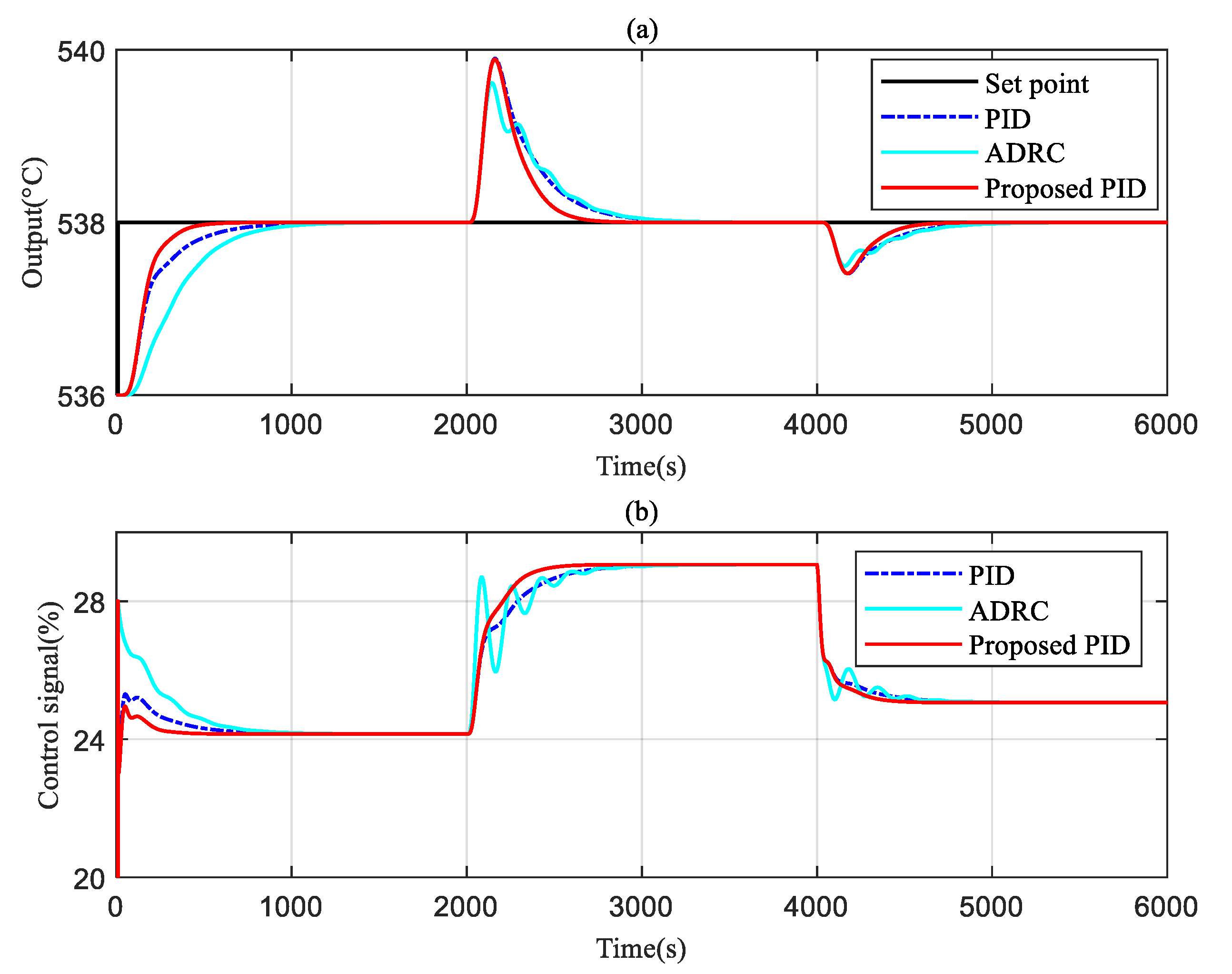
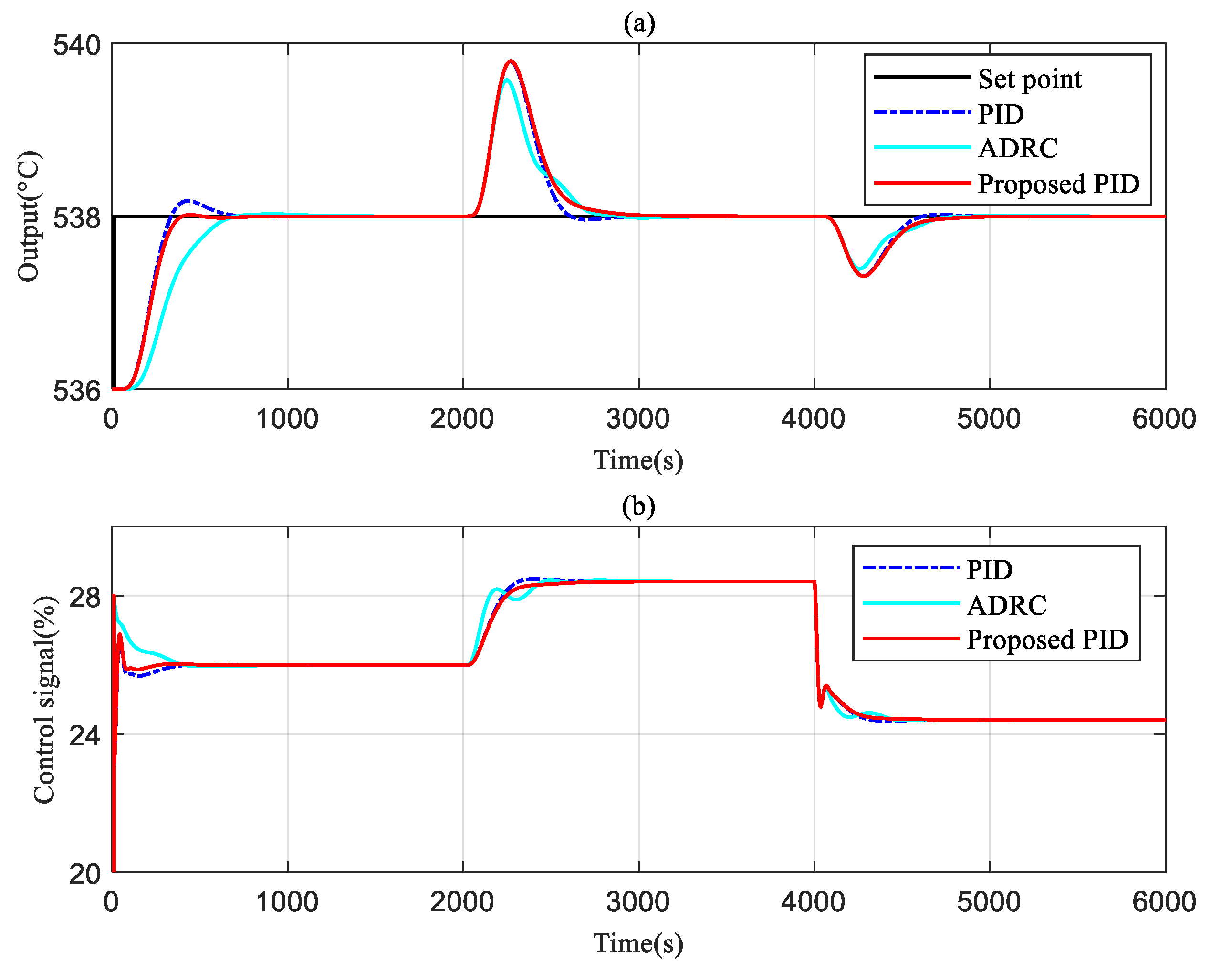
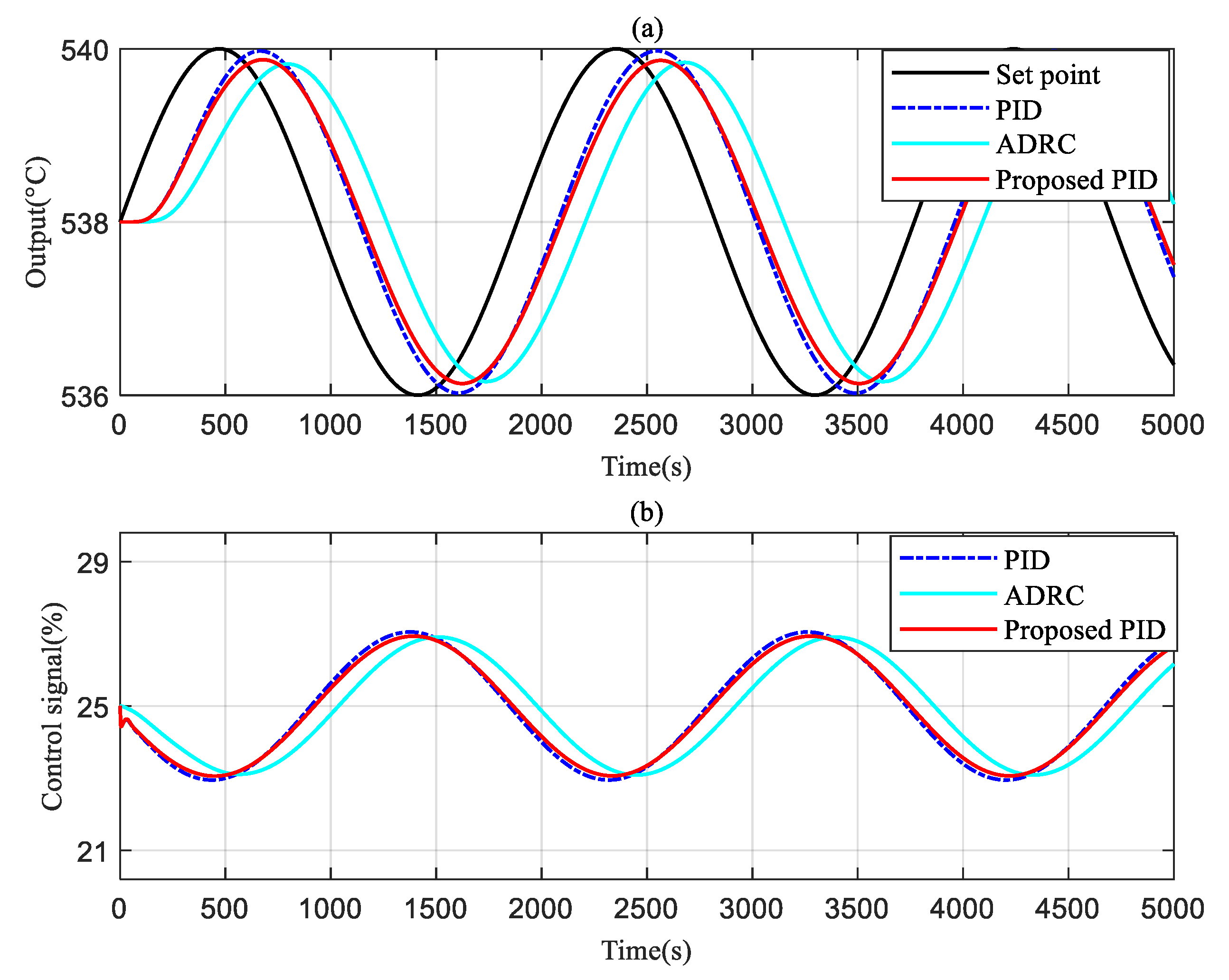
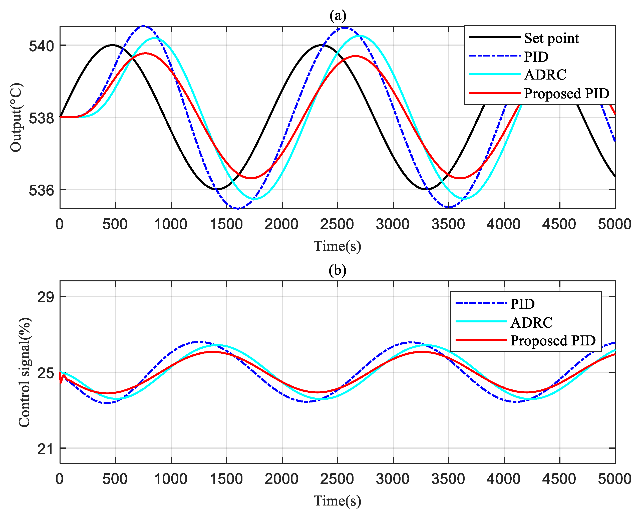
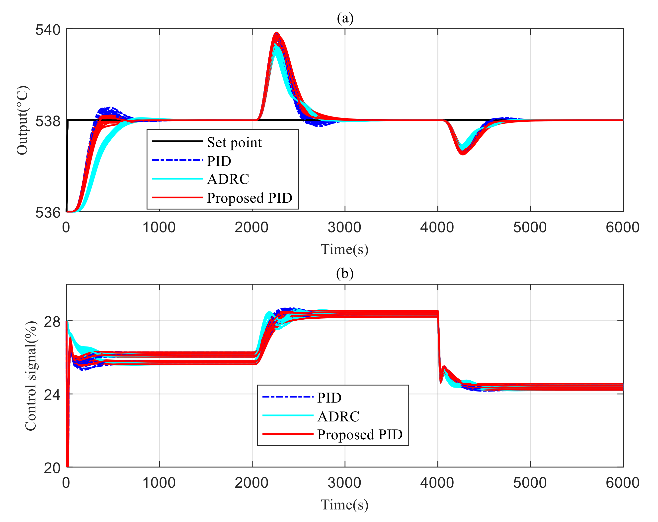
4.1. Control Effect under Nominal Operating Conditions

First, the control effects of the set-point step and the input-disturbance step under nominal operating conditions were considered. The set-point step changes at 10 s, the outer-loop step disturbance (d2), and the inner-loop step disturbance (d1) acted on the system at 2000 s and 4000 s, respectively, and the control effect under 100%, 75%, and 50% load was obtained, as shown in Figure 5, Figure 6 and Figure 7. The integral absolute error (IEA) index was defined as:
IAE = t = 0 e n d | y ( t ) r ( t ) | d t
where r ( t ) and y ( t ) are the set point and the actual value of the SST, respectively. In addition, the units of the IAE index are the integral values of °C. The IAEs applicable to Figure 5, Figure 6 and Figure 7 are provided in Table 2.
It can be seen from Figure 5 that under a 100% load, this method has the fastest tracking speed with no overshoot, and can recover to the steady state in the shortest time when disturbance occurs. It should be noted that although the ADRC has the minimum fluctuation amplitude when the input disturbance occurs, the control amount jitters seriously, which is not conducive to the long-term operation of the de-superheating water valve. It can be seen from Figure 6 that the ADRC has the strongest anti-disturbance performance, but its tracking speed is the slowest, and the PID strategy has obvious overshoot. The proposed PID method in this paper can realize no-overshoot tracking and is faster than the ADRC. It can be seen from Figure 7 that both the ADRC and PID have large overshoot during tracking (19.9% and 45.6%, respectively), while the strategy proposed in this paper has no overshoot and the shortest adjustment time.
In summary, under the conditions of the set-point step change and the input-disturbance step change, the PID control strategy based on integral-gain scheduling, as proposed in this paper, can achieve satisfactory tracking and anti-disturbance performance under 100–50% loads, as listed in Table 2. Therefore, it has a strong application value.
Next, we compared the control performance of each control strategy when the set points changed periodically and the frequency of the set-point periodic change was π / 942 Hz. The control performance shown in Figure 8, Figure 9 and Figure 10 can be obtained when the controller remains unchanged. In addition, the IAE indices shown in Figure 8, Figure 9 and Figure 10 are listed in Table 2.
It can be seen from Figure 8 that the proposed PID can achieve the fastest tracking effect; the IAE indices are 3.3028 × 10³ (proposed PID), 3.7776 × 10³ (PID) and 5.7468 × 10³ (ADRC). The IAE indices further illustrate the advantages of the strategy proposed in this paper. It can be seen from Figure 9 and Figure 10 that the proposed PID can also achieve satisfactory tracking performance.

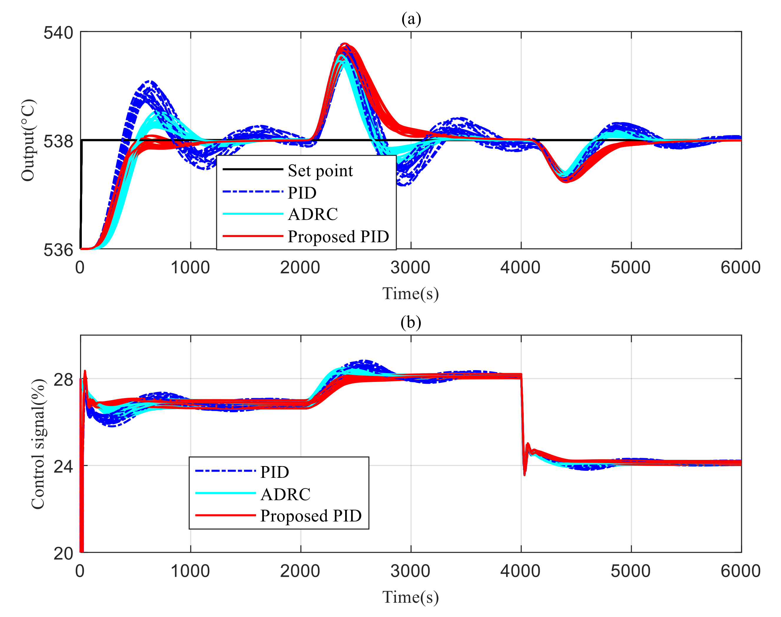
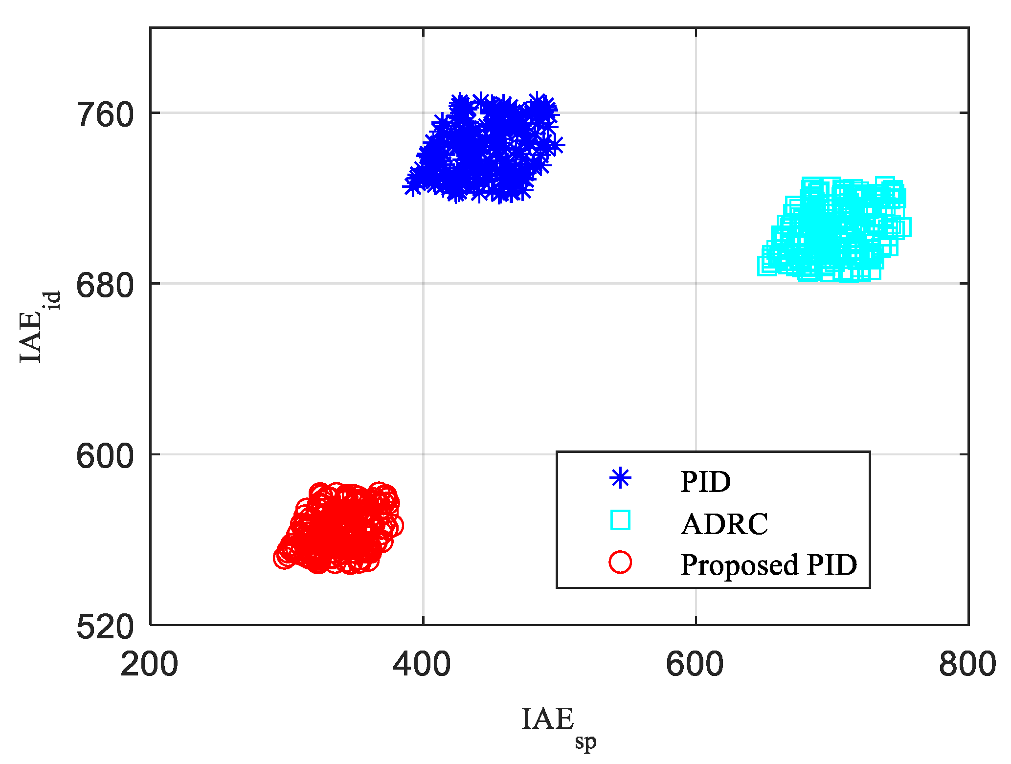
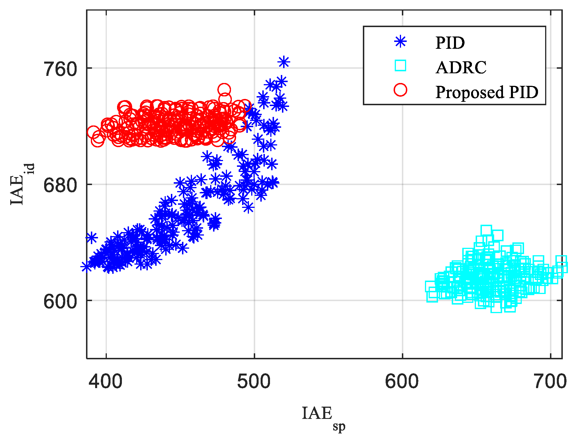
4.2. Control Performance under Uncertain Conditions

Due to the large number of simplifications in the modeling process of the SST system, it was difficult to establish its accurate mathematical model; that is, the SST system had strong uncertainty. Therefore, it was very important to compare the coping ability of the above control strategies when there was such uncertainty in the SST system. In this paper, Monte Carlo experiments were used to compare the control performances of different strategies when the system was uncertain. Under different loads, the time constants and the gain coefficients of the transfer functions of the leading segment and the inert segment, as shown in Table 1, were randomly perturbed within the range of ±10% of the original value, keeping the controller parameters unchanged, and the simulation was repeated 200 times, as shown in Figure 5, Figure 6 and Figure 7. The results obtained are shown in Figure 11, Figure 12 and Figure 13. It can be seen that when there was uncertainty in the SST system (a 10% perturbation interval), the PID and ADRC kept the control effect close to the nominal control, which shows that the three control strategies mentioned above have strong robustness.
In order to better quantitatively measure the ability of the above control strategies to cope with the system uncertainty, the tracking IAE performance index (IAEsp) of 0 to 2000 s and the anti-disturbance IAE performance index (IAEid) of 2000 to 6000 s in the Monte Carlo experiment were statistically calculated, and the distribution of IAEsp and IAEid is shown in Figure 14, Figure 15 and Figure 16 for under-100%, under-75%, and under-50% loads when there was uncertainty in the system. It should be noted that smaller IAEsp and IAEid indicators mean a better control effect, and the more concentrated the control strategy is, the stronger the ability to deal with system uncertainty.

5. Discussions

Through the simulation of the step changes of the set point, the step change of the input disturbance, and sinusoidal change of the set point, it can be seen that the PID strategy based on integral gain scheduling, as proposed in this paper, can achieve the best control effect at 100–50% load, which indicates that this method has strong adaptability, can ensure fast tracking without overshoot under all operating conditions, and has strong disturbance suppression ability.
The proposed PID had the best control effect at around a 100% load, and had the strongest ability to deal with system uncertainty. Under a 75% operating condition, the anti-disturbance performance of the ADRC was best, but its numerical distribution was not concentrated, which indicated that the ability to deal with system uncertainty was weak. Although the anti-disturbance performance of the proposed PID was not as good as that of the ADRC, the ability to deal with system uncertainty was stronger. Figure 16 shows that the proposed PID had the best control effect at around a 50% load, and the strongest ability to deal with system uncertainty. To sum up, the method in this paper had the strongest ability to deal with system uncertainty in the 100–50% load range, indicating that the proposed method has strong robustness.

6. Conclusions

This paper presented a proportional integral derivative (PID) control strategy based on integral gain scheduling to solve the problem of poor control effect of an SST system when the load changes. First, the SST system was introduced, the classical models of operating conditions of 100%, 75%, and 50% unit load were established, and the system’s control difficulties were analyzed. Then, based on the cascade control structure, a control strategy based on the integral gain-scheduling PID was proposed, and the stability of the proposed PID control strategy was analyzed through the calculation of the PID stability region. Then, the control performance of the proposed strategy under 100%, 75%, and 50% operating conditions was verified by simulation, which confirmed the effectiveness of this method and showed strong prospects for applications. In future work, we will try to apply the proposed design method to field applications to further verify its effectiveness and to promote its wider applications.

Author Contributions

Conceptualization, X.C. and P.X.; methodology, X.C.; software, L.W.; validation, G.S. and H.G. (Haiming Gu); investigation, H.G. (Hui Gu); resources, H.Z.; writing—original draft preparation, X.C.; writing—review and editing, P.X.; funding acquisition, H.Z. All authors have read and agreed to the published version of the manuscript.

Funding

This research was funded by the National Natural Science Foundation of China (NSFC) under grant 51706093.

Conflicts of Interest

The authors declare no conflict of interest.

Nomenclature

G 1 ( s ) Leading segment
G 2 ( s ) Inert segment
G c 1 ( s ) Inner loop controller
G c 2 ( s ) Outer loop controller
k p 1 Proportional   coefficient   of   G c 1 ( s )
k p 2 ,   k i 2 ,   k d 2 Proportional   coefficient ,   integral   gain   coefficient   and   differential   gain   coefficient   of   G c 2 ( s )
G e q 1 ( s ) Equivalent transfer function of the inner loop closed-loop system and the inert zone system
ω Angular frequency
a ( ω ) , b ( ω ) Real part and imaginary part of the controlled object
b 0 ,   ω o ,   k p ,   k d Parameters of ADRC
d1Inner loop step disturbance
d2Outer loop step disturbance
r ( t ) Set point of main steam temperature
y ( t ) Main steam temperature
IAEIntegral absolute error

Appendix A

This appendix presents the necessity of the gain scheduling from the perspective of pole assignment. Consider a general first-order system under the nominal condition, G p 0 ( s ) , and a designed a PI controller, G c 0 ( s ) , as follows:
G p 0 ( s ) = K 0 T 0 s + 1
and
G c 0 ( s ) = k p 0 + k i 0 s
where K 0 and T 0 are the system gain and time constant of G p 0 ( s ) , respectively. Note that the general first-order system is a generalized controlled plant, and K 0 and T 0 are unit-less variables; k p 0 and k i 0 are the proportional coefficient and the integral gain coefficients of G c 0 ( s ) , respectively. These coefficients are all unit-less variables.
Then, the closed-loop system, in becoming a second-order system, can be obtained as follows:
G c l 0 ( s ) = G p 0 ( s ) G c 0 ( s ) 1 + G p 0 ( s ) G c 0 ( s ) = K 0 T 0 s + 1 ( k p 0 + k i 0 s ) 1 + K 0 T 0 s + 1 ( k p 0 + k i 0 s ) = K 0 ( k p 0 s + k i 0 ) T 0 s 2 + ( K 0 k p 0 + 1 ) s + K 0 k i 0
Then, the characteristic equation, G c e 0 ( s ) , of G c l 0 ( s ) , can be obtained as follows:
G c e 0 ( s ) = s 2 + ( K 0 k p 0 + 1 ) T 0 s + K 0 k i 0 T 0 = s 2 + 2 ξ ω n s + ω n 2
where ξ = ( K 0 k p 0 + 1 ) 2 K 0 k i 0 T 0 and ω n = K 0 k i 0 T 0 are the damping ratio and the natural frequency of the second-order system, respectively. A smaller ξ means a smaller rise time, and vice versa. A larger ω n means a smaller rise time, and vice versa. If the controlled plant operates far from the nominal condition, K 0 and T 0 become uncertain conditions; then, k i 0 can be applied to adjust the damping ratio and the natural frequency. Based on the fact that k i 0 is related to ξ and ω n simultaneously, the gain-scheduling k i 0 was designed in this paper. Note that the analysis was for PI and a first-order system, due to the fact that it is difficult to calculate characteristic solutions of the characteristic equation for a high-order closed-loop system or a system with a transcendental equation. Simulations are often applied to analyze system dynamics.

References

  1. Wu, Z.L.; Li, D.H.; Xue, Y.L.; Chen, Y.Q. Gain scheduling design based on active disturbance rejection control for thermal power plant under full operating conditions. Energy 2019, 185, 744–762. [Google Scholar] [CrossRef]
  2. Wu, X.; Li, Y.G.; Shen, J. Fuzzy modeling and predictive control of superheater steam temperature for power plant. ISA Trans. 2015, 56, 241–251. [Google Scholar] [CrossRef] [PubMed]
  3. Wu, Z.L.; He, T.; Li, D.H.; Xue, Y.L.; Sun, L.M. Superheated steam temperature control based on modified active disturbance rejection control. Control. Eng. Pract. 2019, 83, 83–97. [Google Scholar] [CrossRef]
  4. Du, Z.P.; Fang, Y.F.; Yang, X.F.; Li, J.Z. Design of PI controller for a class of discrete cascade control systems. IEEE Trans. Autom. Sci. Eng. 2022, 1–9. [Google Scholar] [CrossRef]
  5. Wang, L.B.; Xiao, B.X. PID controller parameters tuning based on pole assignment optimal prediction for power station boiler superheated steam temperature. Int. J. Eng. Technol. 2016, 8, 88–93. [Google Scholar] [CrossRef] [Green Version]
  6. Wu, Z.L.; Li, D.H.; Wang, L.M. Control of the superheated steam temperature: A comparison study between PID and fractional order PID controller. In Proceedings of the 2016 35th Chinese Control Conference (CCC), Chengdu, China, 27–29 July 2016. [Google Scholar] [CrossRef]
  7. Sun, L.; Dong, J.Y.; Li, D.H. Active disturbance rejection control for superheated steam boiler temperatures using the fruit fly algorithm. J. Tsinghua Univ. (Sci. Technol.) 2014, 54, 1288–1292. [Google Scholar] [CrossRef]
  8. Sun, L.; Hua, Q.S.; Shen, J.; Xue, Y.L.; Li, D.H.; Lee, K.Y. Multi-objective optimization for advanced superheater steam temperature control in a 300 MW power plant. Appl. Energy 2017, 208, 592–606. [Google Scholar] [CrossRef]
  9. He, T.; Wu, Z.L.; Li, D.H.; Wang, J.H. A tuning method of active disturbance rejection control for a class of high-order processes. IEEE Trans. Ind. Electron. 2020, 67, 3191–3201. [Google Scholar] [CrossRef] [Green Version]
  10. Shi, G.J.; Wu, Z.L.; Guo, J.; Li, D.H.; Ding, Y.J. Superheated steam temperature control based on a hybrid active disturbance rejection control. Energies 2020, 13, 1757. [Google Scholar] [CrossRef]
  11. Hao, Y.S.; Chen, Z.; Sun, L.; Liang, J.; Zhu, H. Multi-objective intelligent optimization of superheated steam temperature control based on cascaded disturbance observer. Sustainability 2020, 12, 1–24. [Google Scholar] [CrossRef]
  12. Alamoodi, N.; Daoutidis, P. Nonlinear control of coal-fired steam power plants. Control. Eng. Pract. 2017, 60, 63–75. [Google Scholar] [CrossRef]
  13. Wang, Y.L. Nonlinear adaptive control for superheated steam temperature based on interpolation and fitting technique. J. Eng. Therm. Energy Power 2018, 33, 21–25. [Google Scholar] [CrossRef]
  14. Guo, W.; Zhang, P.C.; Li, T.; Zhu, C.P. ARX-Laguerre model PID predictive control and its application in superheated steam temperature control. Control. Eng. China 2021, 28, 524–530. [Google Scholar] [CrossRef]
  15. Lian, L. Main steam temperature control based on variable universe fuzzy dynamic matrix control. Therm. Eng. 2022, 69, 763–778. [Google Scholar] [CrossRef]
  16. Tong, S.; Liu, L.; Wang, P.F. Coordinative two-stage superheated steam temperature linkage control based on multivariable generalized predictive control algorithm. Electr. Power 2020, 53, 215–223. [Google Scholar]
  17. Qu, X.F.; Lv, J.H. Reheat steam temperature prediction and control based on iterative learning algorithm for ultra-supercritical units under deep peak shaving. J. Chin. Soc. Power Eng. 2020, 40, 614–620, 634. [Google Scholar] [CrossRef]
  18. Li, X.M.; Yu, X.H. Robust regulation for superheated steam temperature control based on data-driven feedback compensation. Appl. Energy 2022, 325, 119918. [Google Scholar] [CrossRef]
  19. Chen, Z.; Hao, Y.S.; Sun, L.; Su, Z.G. Phase compensation based active disturbance rejection control for high order superheated steam temperature system. Control. Eng. Pract. 2022, 126, 105200. [Google Scholar] [CrossRef]
  20. Yu, L.; Zhang, C.; Huang, J.; Fei, S.M. Discrete-time sliding-mode switching control scheme with disturbance observer and its application to superheated steam temperature systems. J. Dyn. Syst. Meas. Control.-Trans. ASME 2022, 138, 101003. [Google Scholar] [CrossRef]
  21. Liang, W.P.; Zhang, X. Fuzzy-PID control system of main steam temperature based on intermediate point temperature feedforward. Electr. Power Sci. Eng. 2019, 35, 72–78. [Google Scholar] [CrossRef]
  22. Tu, X.; Shi, J.K.; Yao, K.; Wan, J.; Qiao, F. State variable-fuzzy prediction control strategy for superheated steam temperature of thermal power units. Therm. Sci. 2021, 25, 4083–4090. [Google Scholar] [CrossRef]
  23. Ma, L.Y.; Yan, M. Application of neural network inverse control with PID compensation in superheated steam temperature control of supercritical boiler unit. J. Eng. Therm. Energy Power 2020, 35, 178–184. [Google Scholar] [CrossRef]
  24. Zhan, J.S.; Du, J.; Dong, S.F.; Hu, W. Superheated steam temperature system of thermal power control engineering based on neural network local multi-model prediction. Therm. Sci. 2021, 25, 2949–2956. [Google Scholar] [CrossRef]
  25. Wu, Z.L.; Liu, Y.H.; Li, D.H.; Chen, Y.Q. Performance analysis of improved ADRCs for a class of high-order processes with verification on main steam pressure control. IEEE Trans. Ind. Electron. 2022, 1–10. [Google Scholar] [CrossRef]
  26. Draganescu, M.; Guo, S.; Wojcik, J.; Wang, J.H.; Liu, X.J.; Hou, G.L.; Xue, Y.L.; Gao, Q.R. Generalized predictive control for superheated steam temperature regulation in a supercritical coal-fired power plant. CSEE J. Power Energy Syst. 2015, 1, 69–77. [Google Scholar] [CrossRef]
  27. Wu, Z.L.; Li, D.H.; Xue, Y.L. A new PID controller design with constraints on relative delay margin for first-order plus dead-time systems. Processes 2019, 7, 713. [Google Scholar] [CrossRef] [Green Version]
  28. Zhao, C.; Guo, L. Towards a theoretical foundation of PID control for uncertain nonlinear systems. Automatica 2022, 142, 110360. [Google Scholar] [CrossRef]
  29. Astrom, K.J.; Kumar, P.R. Control: A perspective. Automatica 2014, 50, 3–43. [Google Scholar] [CrossRef]
  30. Zhao, C.; Guo, L. PID controller design for second order nonlinear uncertain systems. Sci. China 2017, 60, 022201. [Google Scholar] [CrossRef] [Green Version]
  31. Ma, D.; Chen, J. Delay Margin of low-order systems achievable by PID controllers. Automatica 2019, 64, 1958–1973. [Google Scholar] [CrossRef]
  32. Hussain, I.; Das, D.C.; Latif, A.; Sinha, N.; Hussain, S.M.S.; Ustun, T.S. Active power control of autonomous hybrid power system using two degree of freedom PID controller. Energy Rep. 2022, 8, 973–981. [Google Scholar] [CrossRef]
  33. Fan, Y.S.; Xu, Z.G.; Chen, L.J. Research on adaptive fuzzy control system of boiler superheated steam temperature based on dynamic characteristic mechanism analysis. Proc. CSEE 1997, 17, 23–28. [Google Scholar] [CrossRef]
  34. Liu, L.Y.; Jin, Q.B. Analytical optimization of IMC-PID design based on performance/robustness tradeoff tuning strategy for the modified Smith structure. J. Low Freq. Noise Vib. Act. Control 2020, 39, 158–173. [Google Scholar] [CrossRef]
Figure 1. Schematic diagram of the structure of the secondary de-superheating water.
Energies 15 08978 g001
Figure 2. Cascade control structure.
Energies 15 08978 g002
Figure 3. The closed-loop system consisted of the PID controller and the equivalent controlled object.
Energies 15 08978 g003
Figure 4. Stability region and parameter distribution of PID parameters under different operating conditions.
Energies 15 08978 g004
Figure 5. Control performance under an operating condition of 100% load (a): outputs, (b): control signals.
Energies 15 08978 g005
Figure 6. Control performance under an operating condition of 75% load (a): outputs, (b): control signals.
Energies 15 08978 g006
Figure 7. Control performance under an operating condition of 50% load ((a): outputs, (b): control signals).
Energies 15 08978 g007
Figure 8. Set-point sinusoidal tracking performance under an operating condition of 100% load (a): outputs, (b): control signals.
Energies 15 08978 g008
Figure 9. Set-point sinusoidal tracking performance under an operating condition of 75% load (a): outputs, (b): control signals.
Energies 15 08978 g009
Figure 10. Set-point inusoidal tracking performance under an operating condition of 50% load (a): outputs, (b): control signals.
Energies 15 08978 g010
Figure 11. Control performance under an operating condition of 100% load with uncertainty in the SST system (a): outputs, (b): control signals.
Energies 15 08978 g011
Figure 12. Control performance under an operating condition of 75% load with uncertainty in the SST system (a): outputs, (b): control signals.
Energies 15 08978 g012
Figure 13. Control performance under an operating condition of 50% load with uncertainty in the SST system (a): outputs, (b): control signals.
Energies 15 08978 g013
Figure 14. IAEsp and IAEid distribution under an operating condition of 100% load.
Energies 15 08978 g014
Figure 15. IAEsp and IAEid distribution under an operating condition of 75% load.
Energies 15 08978 g015
Figure 16. IAEsp and IAEid distribution under an operating condition of 50% load.
Energies 15 08978 g016
Table 1. Transfer function of the SST system under typical operating conditions.
Load/% Leading   Segment   G 1 ( s ) Inert   Segment   G 2 ( s )
100 0.815 ( 18 s + 1 ) 2 1.276 ( 18.4 s + 1 ) 6
75 1.657 ( 20 s + 1 ) 2 1.202 ( 27.1 s + 1 ) 7
50 3.067 ( 25 s + 1 ) 2 1.119 ( 42.1 s + 1 ) 7
Table 2. IAE of different controllers under different operating conditions.
ControllerFigure 5 (× 103)Figure 6 (×103)Figure 7 (×103)Figure 8 (×103)Figure 9 (×103)Figure 10 (×103)
PID1.18521.15632.23725.74684.21035.6937
ADRC1.40411.27281.78803.77766.13397.1943
Proposed PID0.900991.15621.79663.30284.19705.6822
Publisher’s Note: MDPI stays neutral with regard to jurisdictional claims in published maps and institutional affiliations.

