Abstract
Climate change is exacerbated by vehicle emissions. Furthermore, vehicle pollution contributes to respiratory and cardiopulmonary diseases, as well as lung cancer. This requires a drastic reduction in global greenhouse gas emissions for the automobile industry. To address this issue, researchers are required to reduce friction, which is one of the most important aspects of improving the efficiency of internal combustion engines. One of the most important parts of an engine that contributes to friction is the piston ring cylinder liner (PRCL) coupling. Controlling the linear deformation enhances the performance of the engine and, as a result, contributes positively to its performance. The majority of the tests to study the conformability between cylinder liner and piston were carried out on cylinder liners made of cast iron. It is possible to improve the performance of piston ring cylinder liner couplings by implementing new and advanced manufacturing techniques. In this work, a validated finite element model was used to simulate the performance when advanced manufactured materials were adapted. The deformation of the cylinder liner due to thermal and mechanical loads is simulated with five different additive manufactured materials (Inconel 625, Inconel 718, 17-4PH stainless steel, AlSi10Mg, Ti6Al4V). Simulated roundness and straightness errors, as well as maximum deformation, are compared with conventional grey cast iron liner deformation. Some additive manufactured materials, especially Ti6Al4V, show a significant reduction in deformation compared to grey cast iron, both in bore and circumferential deformation. Results show that Ti6Al4V can reduce maximum liner deformation by 36%. In addition, the roundness improved by 36%. The straightness error when Ti6Al4V was used also improved by 44% on one side, with an average of 20% over the four sides. Numerical results indicate that additive manufactured materials have the potential to reduce friction within the piston liner arrangement of internal combustion engines.
1. Introduction
The increase in the number of automotive vehicles worldwide indicates a need to improve fuel economy and reduce emissions in an effort to improve sustainability [1,2]. Reducing the energy loss inside the engine would improve fuel efficiency and maximize the benefit of conversion to sustainable fuels such as hydrogen and biofuels in internal combustion engines [3]. Power cylinders account for roughly half of the mechanical friction losses in an engine [4,5]. According to a study by Holmberg et al. [6], friction within the piston assembly accounts for 45% of energy losses in an internal combustion engine. The performance of internal combustion engines depends significantly on cylinder liners, one of the most important components of these engines. This has led in recent years to intensive research to improve the performance of piston ring cylinder liner (PRCL) couplings.
Conformability between piston rings and cylinder liners is crucial since it affects the consumption of lubricating oil and greenhouse gas emissions [7]. This conformability is altered by the liner deformation in the hot state [8]. The failure of the piston ring to adapt to the deformed cylinder liner bore decreases the engine efficiency and increases emissions due to the loss of combustion pressure and the leak of lubricant oil into the combustion chamber. Therefore, additional tightness is required for the piston rings to maintain the required sealing capabilities. This additional tightness decreases the engine efficiency due to the increase in frictional losses and increases the emission as more fuel will be consumed [7,9]. Enhancing the geometrical performance of the cylinder liner to increase its roundness in the hot state represents a good solution for this dilemma [10,11,12,13].
Enhancing the geometrical performance of the cylinder liner can be achieved through controlling its deformation from the cold state to the hot state. One of the methods is to start the engine in the cold state with a non-circular liner. Alshwawra et al. [14] showed through advanced simulation techniques that starting the engine with an elliptical liner can reduce the roundness error significantly in the hot state. Further enhancement in the liner’s geometrical performance can be achieved with a superposition of this elliptical shape with a conical liner form in the cold state [15]. Flores [13] presented a methodology to control the liner deformation and to enhance its geometrical performance through advanced honing techniques. Alshwawra et al. [16] studied the improvement of the geometrical performance of a freeform honed liner at different operational loads. Edtmayer et al. [17] experimentally found that friction can be reduced by using a liner with a larger bore diameter in its lower half.
Another method to control the liner deformation in the hot state is changing the liner material [12]. Materials or processes for the in-cylinder components of internal combustion engines have been investigated for better friction and performance [18,19]. The majority of the tests to study the conformability between cylinder liner and piston were carried out on cylinder liners made of cast iron [20]. Other materials for cylinder liners are rarely investigated. Thermal stress in cylinder liners made of magnesium alloy and titanium and varying in thickness by 0.5, 1, and 1.5 mm were analyzed. In comparison to cast iron and magnesium alloy, titanium alloy used for cylinder liners has a high heat transfer rate [21]. The grey cast iron liner shows a better geometrical performance compared to an aluminum alloy liner. However, the trends of the deformation and the influence of deformation orders are almost the same for both materials [12]. The thermal expansion coefficient dominates other material properties, including thermal conductivity, Young’s modulus, and Poison’s ratio, in terms of the deformation of the liner to improve the conformability between cylinder liner and piston. The conformability between the cylinder liner and piston can be greatly improved by materials with a negative thermal expansion coefficient [22].
Furthermore, the deformation of the liner can be controlled by redesigning the liner to apply an advanced internal local heating and cooling system. In this regard, advanced additive manufacturing (AM) techniques can be useful. Recently, additive manufacturing technologies have gained a lot of attention and have great potential in the engine manufacturing industry [23]. The main advantage of AM over traditional manufacturing processes is the ability to freely shape complex parts without using traditional manufacturing methods such as extrusion, forging, casting and secondary machining processes [24,25,26,27]. The near net shaping capability makes AM a cost-effective technique because it minimizes waste [25]. In addition, AM offers great flexibility in terms of the type of raw materials [21]. By using AM techniques, non-traditional liner design can be achieved to improve the geometrical performance of the liner and therefore to enhance the engine efficiency [16].
To be able to use the AM techniques for cylinder liner manufacturing, it is important to investigate the compatibility of AM materials for this type of application. Although AM techniques were considered for the production of some of the parts of the internal combustion engine such as the piston [28,29], they have still not been fully investigated for cylinder liners. This work aims for the investigation of the compatibility of AM materials for the fabrication of a cylinder liner from a structural and the geometrical perspective. This article provides a quantitative study of the deformation of AM liners and the trends in their deformation. Cast iron is used as a reference material since it is the most common material used for cylinder liners today. Thermal and mechanical bore deformation of the liner has been investigated. The finite-element model is established in this study to predict bore roundness changes for several AM liners and for the reference liner.
The significance of this work can be summarized by: (i) investigation of the structural compatibility for using AM materials in a cylinder liner, (ii) analyzing the geometrical performance of an additively manufactured cylinder liner, and (iii) providing a comparative analysis for the geometrical performance of different AM materials compared to the conventional grey cast iron.
2. Methodology
2.1. Finite Element Techniques
The changes in conformability between piston rings and cylinder liners have also been attributed to mechanical and thermal factors [30,31]. Many researchers have tested the deformation of the cylinder liner and its influencing factors experimentally [32,33]. However, it is often difficult to quantify frictional losses at full scale when examining different engine configurations. Cycle-to-cycle variations, vibrations, thermal effects, and other factors contributing to noise often overshadow frictional differences [34]. Therefore, researchers used simplified rig component testing. Alternatively, different computational approaches have been used for the prediction and modeling of liner deformation [10,35]. An important and useful tool for analyzing and optimizing the geometry of cylinder liners is the use of finite element analyses (FEA) [36]. Structural analysis of cylinder liners is one of the areas where FEA can be efficiently used [37,38]. Applying this method to the engine’s cylinder liner can predict its deformation and stress distribution, which can be used to improve the design and reliability of the cylinder liner [39]. Additionally, FEA is powerful for studying the dynamic phenomena associated with piston assembly components [40].
This work uses the ANSYS mechanical solver to calculate the liner deformation numerically. This solver has been used in earlier works as well as in the literature to simulate the liner deformation due to its capability to handle the various non-linarites in the finite element model [14,30,41]. The greatest challenge for FEA is the computing requirements and computing capacity, namely computing power, memory and computing time. It is therefore very important to work with sufficiently simple but accurate models [14].
2.2. Physical Model
The simulation model is developed based on the NISSAN CA18 engine. It is a four-stroke, water-cooled, four-cylinder gasoline engine, arranged in a row, with 83 mm cylinder bore, 83.6 mm piston stroke, and a displacement of 1809 cm. The engine was modified to utilize a 1.6 mm thick cylinder dry liner that is made of grey cast iron. The clearance between the engine block and the liner was 80 µm. The liner deformation was measured experimentally for this modified engine at different operational loads [32,33]. The measured deformation was performed at depths varying between 10 mm from the top of the liner and 90 mm from the top of the liner. For the simulation work, the operational point of 4000 rpm/full load was selected, as it represents the highest thermal load and therefore the highest deformation. Further information about this engine, including its detailed specifications and dimensions, can be found in [42].
2.3. Simulation Model
The simulation in this research followed the model validated by Alshwawra et al. [14]. The model focused on the first and half of the second cylinder to capture the different thermal loads generated by adjacent cylinders and their surroundings. It is expected that the deformation of the first and fourth cylinder liners would be more complicated and asymmetric than that of the second or third cylinder liner due to the asymmetric thermal load [12]. The first and half of the second cylinders are shown in Figure 1 as well as their positions in the engine.
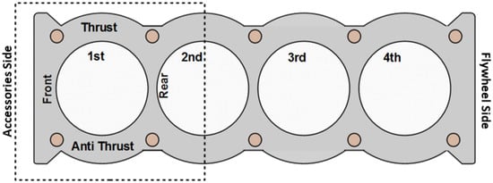
Figure 1.
One and a half cylinder model used in this study with the different sides of the cylinder.
At any specific point, the directional local deformation can be found using the following equation:
where and represent the local deformation and local strain in direction, respectively. The above-mentioned local strain is the total summation of elastic strain and thermal strain . Hook’s law can be used to find the elastic strain:
Here, represents the stress vector, and represents a matrix related to the material’s mechanical properties. To find the thermal strain:
with the thermal expansion coefficient , the strain free temperature , and the operating temperature .
2.4. Computational Mesh
Finite element analysis (FEA) simulation requires accurate meshing in order to produce realistic results. On one hand, a high-density mesh provides the best results, but it also requires a lot of computing time and storage space. On the other hand, the coarse mesh can lead to unrealistic results. Therefore, an adaptive mesh that is neither too fine nor too coarse is used. Grid independency was tested for multiple mesh sizes starting from 25 thousand nodes and 16 thousand elements up to one million nodes and half a million elements. Bases on this test, a mesh size of 197,666 elements and 112,944 nodes was selected. The average calculation time for a supercomputer with 96 processors is 25 h per run. The detailed mesh properties, grid independence test and circumferential position dependent deformation are provided in [14].
2.5. Boundary Conditions
The temperatures of the liner and block inner wall at 4000 rpm/full load were measured experimentally [32]. The measured liner temperature varies between 155 and 198 °C while the measured block temperature varies between 103 and 180 °C. The temperature of the coolant is given to be 80 °C. It was also assumed that the temperature of the outer walls of the block is equal to the coolant temperature, and the bolt pre-tension is 80,000 N. For the calculations, it is assumed that the upper surface is fixed in the axial direction (from top to bottom). As the model is subjected to both thermal and mechanical loads, it is numerically solved using the direct coupled approach, in which the mechanical and thermal matrices are solved in parallel. The accuracy in this case is higher compared to the use of sequential approaches. However, more computational time is required.
The thermal deformation increases with the physical time until it reaches the steady state. The simulated liner deformations were compared with the measured line deformations for the terminal cylinder at 4000 rpm/full load. The simulated deformations showed a good agreement in term of values and trend with the corresponding experimental deformations at different elevations. Based on that, the model is considered to be valid. The detailed model configuration, boundary conditions, temperature distributions, and model validation are explained in [14] for this reference case (grey cast iron liner at 4000 rpm/full load).
2.6. Liner’s Materials
The validated model was used to simulate the liner deformation for different AM materials at 4000 rpm/full load. For the purpose of this study, five additive manufactured materials (Inconel 625, Inconel 718, 17-4PH stainless steel, AlSi10Mg, Ti6Al4V) were analyzed along with the reference cast iron material. Despite having different properties, all the selected materials were used in high-quality, complex-designed products that are exposed to strong mechanical and thermal loads. The properties of the materials are summarized in Table 1.

Table 1.
Properties of AM materials vs. grey cast iron [36,37,38,39].
3. Results and Discussion
The deformation of the liner was simulated at three different depths from the top deck, as well as 10, 50 and 90 mm. The analysis considered front, rear, thrust and anti-thrust sides as shown in Figure 2.
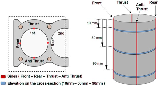
Figure 2.
Locations and orientations of the deformation paths for the cylinder liner.
A variety of methods were used to assess the compatibility of additive manufacturing materials for the cylinder liner. As a starting point, the maximum deformation method was used, since it is the simplest method to study the influence of different materials on the structural behavior of the liner. Data can be collected directly from the ANSYS interface, which shows an overview of the direction and the amplitude of liner deformations. The deformations in the Z direction are very small compared to the deformations in the XY plane; thus, the maximum deformation in the Z direction can be ignored and the comparison is only conducted in the XY plane. The maximum deformation at the three mentioned depths is depicted in Figure 3.
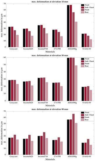
Figure 3.
Maximum deformation at 10, 50 and 90 mm from the top.
It can be seen from the figure that the maximum deformation in the thrust and anti-thrust directions is almost equal but varies in the front and rear directions. This is expected due to the different heat boundary conditions in the front–rear direction. AlSi10Mg increases the maximum deformation of the cylinder liner, as the deformations are almost twice as large as the reference material. This can be referred to as the high thermal expansion coefficient of AlSi10Mg alloy compared with grey cast iron as shown in Table 1. The maximum deformation of the liner decreased when using the Ti6Al4V alloy. Other materials show close maximum deformations to the grey cast iron. Table 2 summarizes the maximum deformation deviations from the grey cast iron.

Table 2.
Deviation of max. deformation at elevations of 10, 50 and 90 mm from the top compared with the reference material.
Table 2 shows the percent deviation of maximum deformation from the reference material (grey cast iron). Compared to the reference material, the distortions are greater when the deviation is positive but less when it is negative. Inconel625, 17-4PH and Ti6Al4V decreased the maximum deformation by different percentages. Ti6Al4V alloy shows the maximum reduction (−36.5%) at 10 mm from the deck. The other AM materials (AlSi10Mg and Inconel718) increase the maximum deformations. The tables also show that the deviation of maximum deformation is consistent at all sides for each material. This means that the deviation is either positive or negative at all sides.
The structural compatibility of the additive manufactured materials for the cylinder liner was also evaluated through the analysis of the change in liner radius. This method enables determining the deformation at all points of the cylinder liner circumference. The radial deformation is calculated at each point using the following set of equations:
where
- Xnew: X-coordinate of the points after deformation;
- Ynew: Y-coordinate of the points after deformation;
- Xo: Initial x-coordinate (before deformation);
- Yo: Initial y-coordinate (before deformation);
- : Value of deformation in x-direction;
- : Value of deformation in y-direction.
Figure 4 shows the radius of the liner cross-section changes at different levels when using AM materials. This change, whether increasing or decreasing, is due to the thermal deformation in the liner. The changes are not in the same direction. The radius increases on the thrust and anti-thrust sides but decreases on the other two sides (front and rear). All materials, including the grey cast iron, show the same behavior. Based on this observation, it can be concluded that more comprehensive details about liner deformation can be obtained by analyzing the deformation at those four points.
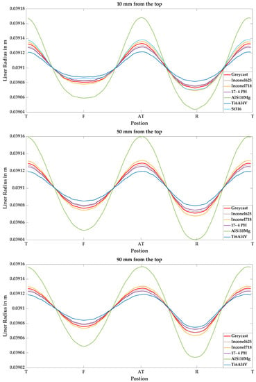
Figure 4.
Radius of the cylinder liner at elevations 10, 50 and 90 mm.
AlSi10Mg has a significantly higher change in radius than the other materials. There is a difference of 60–70 µm between the ideal shape radius (0.0391 m) and the radius on the four main sides of the liners (thrust, anti-thrust, front, and rear). The radius of the Ti6Al4V alloy liner was the closest to the non-deformed liner. Other additive manufactured materials showed different deformation behaviors. Inconel625 and 17-4PH show a slight improvement in the radius curve compared to the grey cast iron.
This figure illustrates the circumferential deformations at the different main elevations of the cylinder liner (10, 50, and 90 mm). Due to the observed differences in radius between the elevation layers, the bore deformation along the elevation was studied. The investigation of the bore deformation plays an important role in obtaining a comprehensive description of the deformations of the additively manufactured liners. As observed previously, the greatest deformation in the cylinder liners occurs on the four main sides (thrust, anti-thrust, front, and rear). These four sides were therefore selected for investigation, as shown in Figure 5.
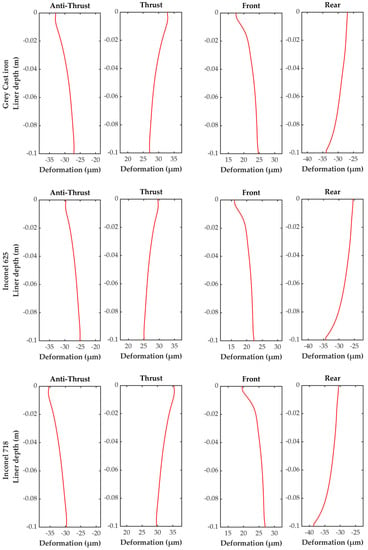
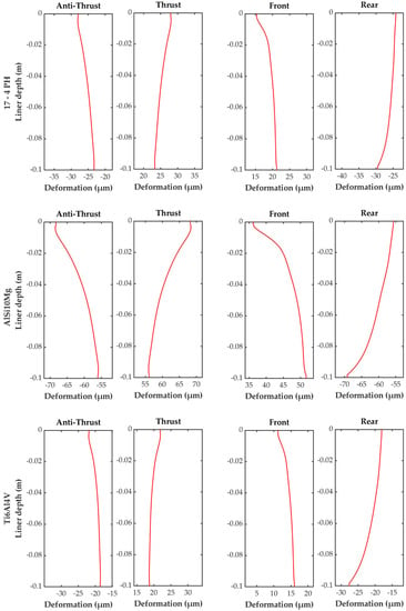
Figure 5.
Bore deformation for grey cast iron and AM material.
It is apparent in Figure 5 that deformation varies from side to side. There is usually more deformation in the upper part than in the lower part. Inconel625, 17-4P, Ti6Al4V and Inconel718 have a very similar bore deformation trend similar to the grey cast iron. These liners were deformed into a conical shape in the thrust–anti-thrust direction. The difference in deformation on the thrust and anti-thrust was less than 5 µm. In the case of AlSi10Mg, the bore deformation looked different. The top part was even more deformed than the other materials. There could have been a difference of up to 15 µm, and the shape remained conical.
In order to determine whether additive manufactured materials affect the roundness of the liner’s cross-section, the roundness errors were calculated at different elevations (10, 50, and 90 mm) using the least squares circle (LSC) method. In this method, a specific center point of the circle is set in such a way that the sum of the squares of the deviation is minimized for the measured profile. The inscribed circle and the circumscribed circle are drawn next. The roundness error ΔR is the difference between the radius of the inscribed circle and the radius of the circumscribed circle as shown in Figure 6a.
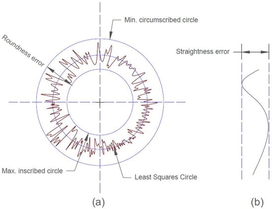
Figure 6.
(a) Roundness error; (b) straightness error.
While the straightness error represents the change in radius over depth, the roundness error represents the change in radius over circumference. Figure 6b shows how to calculate the straightness error as the minimum distance between two straight lines that contain all the points. Table 3 shows the roundness error of the six liners (five additive manufactured materials and grey cast iron). Keeping in mind that in the cold state, all materials exhibited no roundness error, the roundness errors in the fired state increased significantly. There was a variation in the roundness error of the six liners. Figure 7 shows the deviation of the roundness error (RE) from the roundness error of the grey cast iron liner.

Table 3.
Roundness deviation of the liner in µm.
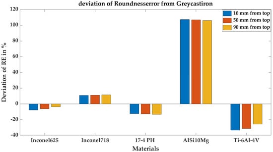
Figure 7.
Deviation of roundness error of AM materials from grey cast iron.
Materials such as Ti6Al4V and 17-4PH have a significant improvement in roundness compared to grey cast iron. With an approximate roundness error of 39 µm, Ti6Al4V had the lowest roundness error. The two Inconel materials show different performances. While Inconel 625 had better roundness values than grey cast iron, the roundness error was greater for Inconel 718 than for grey cast iron. AlSi10Mg had about a 120 µm roundness error, which is very high compared to the grey cast iron. A larger roundness error implies that the piston rings need increased pretension to prevent leakage. This increases the frictional losses to a certain extent [1]; therefore, the friction with AlSi10Mg could increase compared to the grey cast iron. In contrast, friction can be reduced when Ti6Al4V and 17-4PH materials are used.
Table 4 shows the straightness error of the six liners (five AM materials and grey cast iron), while Figure 8 shows a deviation in the straightness error (SE) of the AM materials from the straightness error of the grey cast iron. Note that there was no straightness error in the cold state. The table shows that Ti6Al4V had the best and smallest straightness error between all material alloys but not from all sides. On the rear side, the straightness error value (9.5 µm) was higher than the value for the reference material. The straightness error with Inconel625 on the rear also had a higher value compared with grey cast iron. Again, AlSi10Mg had the largest straightness error on both sides: front and rear (15.5 and 13.5 µm). In general, the ranking from this analysis remains the same as for the elevation of the roundness error.

Table 4.
Straightness deviation of the liner in µm.
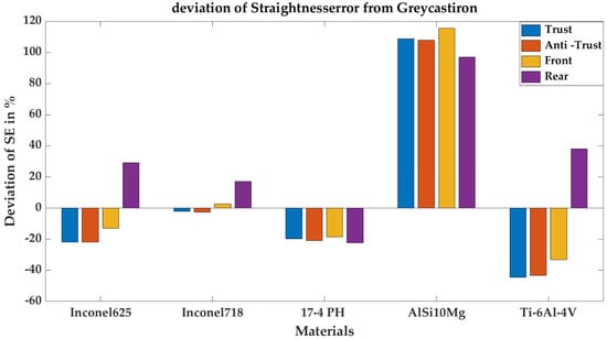
Figure 8.
Deviation of straightness error of AM materials from grey cast iron.
These results show that AM materials can be used as an alternative to conventional materials from a structural point of view. Some of these AM alloys will even enhance the geometrical performance of the cylinder liner and therefore enhance the overall efficiency of the engine. For example, the Ti6Al4V alloy reduces the average roundness error by 30% and the average straightness error by 21% compared with the grey cast iron.
4. Conclusions
Materials used in additive manufacturing have proven themselves in many fields for years. Thus, this technology can possibly be used in new areas that require revolutionary design and manufacturing processes. This technology provides a good development opportunity for the piston ring cylinder liner coupling, which is considered as an important component of internal combustion engines. The utilization of AM techniques for the manufacturing process of liners can allow for new degrees of freedom in terms of cooling and forming of the liner. This can improve the conformability of the piston ring to the cylinder liner, which is essential since the lack of conformability can affect engine performance and energy consumption.
One of the biggest barriers for using additive manufacturing in liners is the lack of knowledge about whether AM materials are suitable for use in cylinder liners. In this work, the structural compatibility of additive manufactured materials for the cylinder liner was investigated using a validated finite-element model. The influences and effects of the AM materials on the liner deformation at 4000 rpm/full load were simulated and compared to the conventional grey cast iron. Based on simulation results, the maximum deformation, the bore and circumferential deformation, and the roundness and straightness errors were determined.
The results show that the maximum liner deformation as well as the bore and circumferential deformations of the AM liners are comparable to the grey cast iron. Ti6Al4V, Inconel 625 and 17-4PH materials can reduce the maximum deformation on average by 32%, 7%, and 13%, respectively, while AlSi10Mg and Inconel 718 increase the maximum deformation on average by 107% and 11%, respectively. From a geometrical performance aspect, the roundness error at hot state decreased by using Ti6Al4V, Inconel 625 and 17-4PH materials. Maximum reduction of 36% compared to grey cast iron was achieved when using Ti6Al4V material. The straightness error at hot state was reduced by about 20% for the 17-4PH material. The enhancement of the geometrical performance of the liner using Ti6Al4V, Inconel 625 and 17-4PH materials can be reflected on the efficiency on the PRCL coupling and therefore on the total energy efficiency.
These results indicate that additive manufactured materials can be used as a liner material from a structural point of view. However, a full understanding of the additively manufactured cylinder liners and their impacts on the tribological performance of the piston group would require more detailed investigations. Moreover, a revolutionary design for cylinder liners can be achieved in order to control the liner deformation and tribological behavior. This can improve internal combustion engine technology and maximize the benefits of conversion to fuels. The findings of this work present a step in this direction.
Author Contributions
Conceptualization, A.A.; methodology, A.A.; software, A.A. and A.A.S.; validation, A.A.; formal analysis, A.A.S. and A.S.; investigation, A.A.S.; resources, F.D.; data curation, A.A. and A.S.; writing—original draft preparation, A.S.; writing—review and editing, A.A., A.A.S., A.S. and F.D.; visualization, A.A.S. and A.S.; supervision, F.D.; project administration, A.A.; funding acquisition, A.A. and F.D. All authors have read and agreed to the published version of the manuscript.
Funding
Partial fund is given from Leibniz University Hannover. The study is based on earlier funded research work from German Federal Ministry for Economic Affairs and Energy (BMWi) within the cooperation project (Antriebsstrang 2025). The study is intended as a preparation for a new research project in conjunction with additive manufacturing. The publication of this article was funded by the Open Access Fund of the Leibniz Universität Hannover.
Acknowledgments
This publication was made possible with the support and within the interdisciplinary setting of the Arab–German Young Academy of Sciences and Humanities (AGYA). AGYA is supported by the German Federal Ministry of Education and Research (BMBF). The authors also would like to thank F. Pohlmann-Tasche and F. Stelljes for sharing their experiences and fruitful discussions.
Conflicts of Interest
The authors declare no conflict of interest.
References
- Dargay, J.; Gately, D.; Sommer, M. Vehicle Ownership and Income Growth, Worldwide: 1960–2030. Energy J. 2007, 28, 143–170. [Google Scholar] [CrossRef]
- King, J. The King Review of Low-Carbon Cars; LowCVP: London, UK, 2007. [Google Scholar]
- Rahmani, R.; Rahnejat, H.; Fitzsimons, B.; Dowson, D. The Effect of Cylinder Liner Operating Temperature on Frictional Loss and Engine Emissions in Piston Ring Conjunction. Appl. Energy 2017, 191, 568–581. [Google Scholar] [CrossRef]
- Heywood, J.B. Internal Combustion Engine Fundamentals, 2nd ed.; McGraw-Hill Education: New York, NY, USA, 2018; Volume 2012. [Google Scholar]
- Kurbet, S.N.; Malagi, R.R. Review on Effects of Piston and Piston Ring Dynamics Emphasis with Oil Consumption and Frictional Losses in Internal Combustion Engines. In Proceedings of the 8th International Conference on Engines for Automobiles, SAE Technical Papers, Capri, Italy, 16 September 2007. [Google Scholar]
- Holmberg, K.; Andersson, P.; Erdemir, A. Global Energy Consumption Due to Friction in Passenger Cars. Tribol. Int. 2012, 47, 221–234. [Google Scholar] [CrossRef]
- Styles, G.; Rahmani, R.; Rahnejat, H.; Fitzsimons, B. In-Cycle and Life-Time Friction Transience in Piston Ring-Liner Conjunction under Mixed Regime of Lubrication. Int. J. Engine Res. 2014, 15, 862–876. [Google Scholar] [CrossRef]
- Liu, N.; Wang, C.; Xia, Q.; Gao, Y.; Liu, P. Simulation on the Effect of Cylinder Liner and Piston Ring Surface Roughness on Friction Performance. Mech. Ind. 2022, 23, 8. [Google Scholar] [CrossRef]
- Delprete, C.; Razavykia, A. Piston Dynamics, Lubrication and Tribological Performance Evaluation: A Review. Int. J. Engine Res. 2018, 21, 725–741. [Google Scholar] [CrossRef]
- Koch, F.; Decker, P.; Gülpen, R.; Quadflieg, F.-J.; Loeprecht, M. Cylinder Liner Deformation Analysis—Measurements and Calculations. SAE Tech. Pap. 1998, 107, 838–847. [Google Scholar] [CrossRef]
- Selmani, E.; Delprete, C.; Bisha, A. Cylinder Liner Deformation Orders and Efficiency of a Piston Ring-Pack. E3S Web Conf. 2019, 95, 04001. [Google Scholar] [CrossRef]
- Alshwawra, A.; Pohlmann-Tasche, F.; Stelljes, F.; Dinkelacker, F. Cylinder Liner Deformation—An Investigation of Its Decomposition Orders under Varied Operational Load. SAE Tech. Pap. 2022, 2022-01-1040. [Google Scholar] [CrossRef]
- Flores, G.K. Graded Freeform Machining of Cylinder Bores Using Form Honing. SAE Tech. Pap. 2015, 2015-01-1725. [Google Scholar] [CrossRef]
- Alshwawra, A.; Pasligh, H.; Hansen, H.; Dinkelacker, F. Increasing the Roundness of Deformed Cylinder Liner in Internal Combustion Engines by Using a Non-Circular Liner Profile. Int. J. Engine Res. 2021, 22, 1214–1221. [Google Scholar] [CrossRef]
- Alshwawra, A.; Pohlmann-Tasche, F.; Stelljes, F.; Dinkelacker, F. Enhancing the Geometrical Performance Using Initially Conical Cylinder Liner in Internal Combustion Engines—A Numerical Study. Appl. Sci. 2020, 10, 3705. [Google Scholar] [CrossRef]
- Alshwawra, A.; Pohlmann-Tasche, F.; Stelljes, F.; Dinkelacker, F. Effect of Freeform Honing on the Geometrical Performance of the Cylinder Liner—Numerical Study. SAE Int. J. Engines 2022, 16, 2023. [Google Scholar] [CrossRef]
- Edtmayer, J.; Lösch, S.; Hick, H.; Walch, S. Comparative Study on the Friction Behaviour of Piston/Bore Interface Technologies. Automot. Engine Technol. 2019, 4, 101–109. [Google Scholar] [CrossRef]
- Rejowski, E.D.; Soares, E.; Roth, I.; Rudolph, S. Cylinder Liner in Ductile Cast Iron for High Loaded Combustion Diesel Engines. J. Eng. Gas Turbines Power 2012, 134, 072807. [Google Scholar] [CrossRef]
- Baby, A.K.; Priyaranjan, M.; Deepak Lawrence, K.; Rajendrakumar, P.K. Tribological Behaviour of Hypereutectic Al-Si Automotive Cylinder Liner Material under Dry Sliding Wear Condition in Severe Wear Regime. Proc. Inst. Mech. Eng. Part J J. Eng. Tribol. 2021, 235, 1450–1462. [Google Scholar] [CrossRef]
- Abouchi, M.; Basturk, S. An Investigation on the Friction Losses between Cylinder Liner and Piston Rings. Sustain. Eng. Innov. 2022, 4, 146–155. [Google Scholar] [CrossRef]
- Seifi, M.; Salem, A.; Beuth, J.; Harrysson, O.; Lewandowski, J.J. Overview of Materials Qualification Needs for Metal Additive Manufacturing. JOM 2016, 68, 747–764. [Google Scholar] [CrossRef]
- Migita, R. Effects of Material Properties on Bore Deformation of Engine Cylinder Liner; Kyushu University: Kyushu, Japan, 2020. [Google Scholar]
- Gray, J.; Depcik, C. Review of Additive Manufacturing for Internal Combustion Engine Components. SAE Int. J. Engines 2020, 13, 617–632. [Google Scholar] [CrossRef]
- Liu, S.; Shin, Y.C. Additive Manufacturing of Ti6Al4V Alloy: A Review. Mater. Des. 2019, 164, 107552. [Google Scholar] [CrossRef]
- Nemova, D.; Kotov, E.; Andreeva, D.; Khorobrov, S.; Olshevskiy, V.; Vasileva, I.; Zaborova, D.; Musorina, T. Experimental Study on the Thermal Performance of 3D-Printed Enclosing Structures. Energies 2022, 15, 4230. [Google Scholar] [CrossRef]
- Frazier, W.E. Metal Additive Manufacturing: A Review. J. Mater. Eng. Perform. 2014, 23, 1917–1928. [Google Scholar] [CrossRef]
- Guo, N.; Leu, M.C. Additive Manufacturing: Technology, Applications and Research Needs. Front. Mech. Eng. 2013, 8, 215–243. [Google Scholar] [CrossRef]
- Millo, F.; Piano, A.; Roggio, S.; Bianco, A.; Pesce, F.C.; Vassallo, A.L. Numerical Assessment of Additive Manufacturing-Enabled Innovative Piston Bowl Design for a Light-Duty Diesel Engine Achieving Ultra-Low Engine-Out Soot Emissions. SAE Int. J. Engines 2021, 15, 427–443. [Google Scholar] [CrossRef]
- Kumaran, M.; Senthilkumar, V.; Justus Panicker, C.T.; Shishir, R. Concept Design and Analysis of Multi-Layer and Multi-Process Piston of SS316L and AlSi10Mg by Additive Manufacturing. In Recent Advances in Materials and Modern Manufacturing; Palani, I.A., Sathiya, P., Palanisamy, D., Eds.; Springer Nature: Singapore, 2022; pp. 441–446. [Google Scholar]
- Lu, Y.; Liu, C.; Zhang, Y.; Wang, J.; Yao, K.; Du, Y.; Müller, N. Evaluation on the Tribological Performance of Ring/Liner System under Cylinder Deactivation with Consideration of Cylinder Liner Deformation and Oil Supply. PLoS ONE 2018, 13, 0204179. [Google Scholar] [CrossRef] [PubMed]
- Yang, Z.; Li, B.; Yu, T. Distortion Optimization of Engine Cylinder Liner Using Spectrum Characterization and Parametric Analysis. Math. Probl. Eng. 2016, 2016, 9212613. [Google Scholar] [CrossRef]
- Hitosugi, H.; Nagoshi, K.; Ebina, M.; Furuhama, S. Study on Cylinder Bore Deformation of Dry Liner in Engine Operation. JSAE Rev. 1996, 17, 113–119. [Google Scholar] [CrossRef]
- Fujimoto, H.; Yoshihara, Y.; Goto, T.; Furuhama, S. Measurement of Cylinder Bore Deformation during Actual Operating Engines. SAE Tech. Pap. 1991, 910042. [Google Scholar] [CrossRef]
- Johansson, S.; Nilsson, P.H.; Ohlsson, R.; Rosén, B.G. Experimental Friction Evaluation of Cylinder Liner/Piston Ring Contact. Wear 2011, 271, 625–633. [Google Scholar] [CrossRef]
- Maassen, F.; Koch, F.; Schwaderlapp, M.; Ortjohann, T.; Dohmen, J. Analytical and Empirical Methods for Optimization of Cylinder Liner Bore Distortion. SAE Tech. Pap. 2001, 2001-01-0569. [Google Scholar] [CrossRef]
- Barbieri, S.G.; Mangeruga, V.; Giacopini, M.; Laurino, C.; Lorenzini, M. A Finite Element Numerical Methodology for the Fatigue Analysis of Cylinder Liners of a High Performance Internal Combustion Engine. Key Eng. Mater. 2019, 827, 288–293. [Google Scholar] [CrossRef]
- Murakami, H.; Nakanishi, N.; Ono, N.; Kawano, T. New Three-Dimensional Piston Secondary Motion Analysis Method Coupling Structure Analysis and Multi Body Dynamics Analysis. SAE Int. J. Engines 2012, 5, 42–50. [Google Scholar] [CrossRef]
- Jafari, A.A.; Khalili, S.M.R.; Azarafza, R. Transient Dynamic Response of Composite Circular Cylindrical Shells under Radial Impulse Load and Axial Compressive Loads. Thin-Walled Struct. 2005, 43, 1763–1786. [Google Scholar] [CrossRef]
- Li, M.H.; Dong, D.D. Finite Element Analysis of the Cylinder Liner of a 280 Diesel Engine. Adv. Mater. Res. 2013, 616–618, 1745–1750. [Google Scholar] [CrossRef]
- Malagi, R.R.; Kurbet, S.N.; Gowrishenkar, N. Finite Element Study on Piston Assembly Dynamics in Multicylinder Internal Combustion Engine. SAE Tech. Pap. 2011, 2011-01-1075. [Google Scholar] [CrossRef]
- Liang, X.; Wang, Y.; Huang, S.; Yang, G.; Tang, L.; Cui, G. Investigation on Cylinder Bore Deformation under Static Condition Based on Fourier Decomposition. SAE Tech. Pap. 2017, 2017-01-0366. [Google Scholar] [CrossRef]
- Flammang, J.M. Standard Catalog of Imported Cars 1946–1990, 1st ed.; Kp Books: Iola, WI, USA, 1992; ISBN 0873411587. [Google Scholar]
Publisher’s Note: MDPI stays neutral with regard to jurisdictional claims in published maps and institutional affiliations. |
© 2022 by the authors. Licensee MDPI, Basel, Switzerland. This article is an open access article distributed under the terms and conditions of the Creative Commons Attribution (CC BY) license (https://creativecommons.org/licenses/by/4.0/).