Article

Environmental and Economic Impact Assessments of a Photovoltaic Rooftop System in the United Arab Emirates

1
Department of Industrial Engineering, American University of Sharjah, Sharjah P.O. Box 26666, United Arab Emirates
2
Department of Biology, Chemistry and Environmental Sciences, American University of Sharjah, Sharjah P.O. Box 26666, United Arab Emirates
*
Author to whom correspondence should be addressed.
Energies 2022, 15(22), 8765; https://doi.org/10.3390/en15228765
Submission received: 24 October 2022 / Revised: 15 November 2022 / Accepted: 17 November 2022 / Published: 21 November 2022

Abstract

:
The shift toward renewable energy resources, and photovoltaic systems specifically, has gained a huge focus in the past two decades. This study aimed to assess several environmental and economic impacts of a photovoltaic system that installed on the rooftop of an industrial facility in Dubai, United Arab Emirates (UAE). The life cycle assessment method was employed to study all the flows and evaluate the environmental impacts, while several economic indicators were calculated to assess the feasibility and profitability of this photovoltaic system. The results showed that the production processes contributed the most to the environmental impacts, where the total primary energy demand was 1152 MWh for the whole photovoltaic system, the total global warming potential was 6.83 × 10⁻² kg CO2-eq, the energy payback time was 2.15 years, the carbon dioxide payback time was 1.87 years, the acidification potential was 2.87 × 10⁻⁴ kg SO2-eq, eutrophication potential was 2.45 × 10⁻⁵ kg PO43-eq, the ozone layer depletion potential was 4.685 × 10⁻⁹ kgCFC-11-eq, the photochemical ozone creation potential was 3.81 × 10⁻⁵ kg C2H4-eq, and the human toxicity potential was 2.38 × 10⁻² kg1,4-DB-eq for the defined function unit of the photovoltaic system, while the economic impact indicators for the whole system resulted in a 3.5 year payback period, the benefit to cost ratio of 11.8, and 0.142 AED/kWh levelized cost of electricity. This was the first study to comprehensively consider all of these impact indicators together. These findings are beneficial inputs for policy- and decision-makers, photovoltaic panel manufacturers, and photovoltaic contractors to enhance the sustainability of their processes and improve the environment.

1. Introduction

Electricity consumption is an indicator of the industrial and economic growth for countries. This is apparent in China, which has the greatest contribution of the world’s industrial production, with an approximate contribution of 28% in 2019. The increase in global electricity demand from 1990 to 2019 was 228% [1], but it is forecasted by the International Energy Agency (IEA) to increase by more than 50% in 2030 [2]. The harmful environmental impacts of this continuously increasing demand are inevitable with the current main dependence on conventional energy resources [3] such as climate change and global warming due to massive greenhouse gas emissions. Thus, the dependence on renewable and clean energy resources has become one of the top priorities and visions for all countries [4].
Consequently, governments worldwide have invested significantly in regulating and adopting renewable energy resources to mitigate the risk of global warming and enhance the quality of the environment. Additionally, based on the current achievements and potential plans in generating electricity from renewable resources, the contribution of these resources is expected to reach 50% of the total energy generation between 2020 and 2025 [5]. This can be noticed from the published statistics by the International Renewable Energy Agency (IRENA) on the global trends in renewable energy from 2010 to 2020, which approached an ~2800 GW installed capacity in 2020 [6]. Additionally, the largest contributing regions in renewable energy projects are in Asia, which has 45.95% of the global total installed capacity with 1286 GW [7]; this is because China is the largest consumer and has put numerous efforts to decrease the use of conventional resources and depend on renewable resources.
Solar energy is a type of renewable energy resource that is plentiful, inconsumable, free, and safe [8]. Furthermore, it is known for its simplicity and effectiveness compared to other resources [9], in addition to the evolving technology that has led to a remarkable reduction in costs and promoted the use of solar energy [10]. The total contribution of solar energy is expected to reach 31% of total renewable energy resources in 2030 [11]. The latest updated statistics in 2020 showed that the top ten countries that contributed the most to the installation of solar energy projects were China, the USA, Japan, Germany, India, Italy, Australia, Vietnam, the Republic of Korea, and Spain.
Although there has been a noticeable shift toward renewable energy, the impact of climate change is still a global challenge and a major environmental risk. The main impact of climate change is global warming [12], which refers to the slow and gradual increase in the temperature of the Earth’s atmosphere due to the increase in the heat hitting the Earth from the Sun and being trapped in the atmosphere (infra-red radiation) instead of being radiated into outer space,, which happens due to greenhouse gas emissions [13].
Greenhouse gases include several gases such as carbon dioxide (CO2), which is the most popular gas as it is common and usually used to measure the global warming and other environmental impacts. It mainly results from burning fossil fuels, tree products, solid waste, and soil degradation, fluorinated gases including perfluorocarbons and hydrofluorocarbons, which are long-lasting and very warming gases, and result from several household, industrial, and chemical activities. Methane, which has a warming effect that is 28–36 times the effect of CO2, results from the production and transportation processes of natural gas, oil or coal, the anaerobic decay of organic waste, livestock, and agricultural practices, nitrous oxide (NOx), which lasts for long period of time in the atmosphere, the combustion of fossil fuel and soil waste, industrial activities, and agricultural practices. Sulphur hexafluoride, which lasts for thousands of years in the upper atmosphere, is used in specialized medical procedures and water vapor [12,13,14,15]. Another component that causes global warming is black carbon (BC), which are very small carbon particles (PM2.5 and PM10) that result from the incomplete combustion of biofuel, fossil fuels, and biomass. These particles can absorb the heat of the Sun a million times more than CO2 [12]. However, several sectors contribute to greenhouse gas emissions, but the energy sector is responsible for approximately 72% of the total greenhouse gas emissions and 31% of the energy sector demand is to generate electricity and heat from non-renewable resources [16]. This highlights the importance of focusing on using renewable energy resources to cover the electricity and heating demands.
In the context of the United Arab Emirates (UAE), electricity consumption is rapidly increasing with an overall growth of approximately 310% in the past twenty years [17]. While dependence on renewable energy resources took place in 2013 with a noticeable boost in 2019 [18], such a boost was attributed to the proven feasibility of the initially installed PV systems accompanied by the rapid increase in the registered PV contracting companies, which led to significant growth in the market of PV systems. In addition, numerous milestones have been adopted and achieved by the UAE regarding the renewable energy sector such as having the headquarters for the International Renewable Energy Agency (IRENA), hosting the annual World Future Energy Summit, establishing the Emirates Nuclear Energy Corporation (ENEC), and launching the Energy Strategy 2050, which aims to increase the share of clean energy by 50% [19]. Furthermore, the UAE’s greenhouse gas emissions per capita have reached 21.26 tons, where electricity and heat are the main contributing sectors with a total share of 88.2 million tons [20].
To evaluate PV systems worldwide, it is crucial to evaluate the energy generated by these systems, the energy consumed throughout the life cycle of these systems, and their environmental and economic impacts. This can be achieved by conducting a life cycle assessment (LCA), which is a standardized and systematic method for calculating the environmental impacts during the life cycle of systems [21,22,23]. In addition, LCA helps policy and decision-makers by mapping and highlighting the environmental impacts and the main contributors to the global warming problem [22,24,25,26,27].
As the UAE moves toward a net zero strategy, this paper aimed to assess the environmental and economic impacts of a PV system using several environmental and economic indicators such as the CO2 payback time (CO2PBT), energy payback time (EPBT), global warming potential (GWP), acidification potential (AP), ozone layer depletion potential (ODP), human toxicity potential (HTP), photochemical ozone creation potential (POCP), eutrophication potential (EP), payback period (PBP), benefit to cost ratio (BCR), and levelized cost of electricity (LCOE) using as a case study a multi-crystalline (poly) PV system installed on a rooftop of an industrial facility in Dubai, UAE. The rest of this paper is organized as follows. A literature review of the relevant studies is presented in Section 2, followed by the methodology in Section 3, then the results are summarized in Section 4. Section 5 includes the discussion, and finally, Section 6 includes our conclusions and future work.

2. Literature Review

A LCA is “the compiling and evaluation of the inputs and outputs and the potential environmental impacts of a product system during its lifetime”, as defined by the international organization of standardization (ISO) [28,29], where inputs represent the required resources and outputs are emissions to air, soil, and water. LCA helps in determining the environmental hotspots throughout the life processes and accordingly assists in improving the processes and making them more environmentally friendly.
The first research work that studied the environmental impacts of PV systems was back in 1970 by [30], where the total energy used to produce PV solar cells was assessed, and it was concluded that the EPBT for monocrystalline PV solar cells was 12 years, which was almost half its lifetime (25 years). Most of the conducted studies focused on greenhouse gas emissions and their consequences on the environment, especially their impact on climate change and global warming [31,32,33]. For instance, [34] assessed the life cycle of a PV project and found that the greenhouse gas emissions would approximately reach 16g CO2-eq/kWh over 50 years, while the EPBT for the same project was 0.9 years, which was less than 3% of the project’s lifetime. Furthermore, different production processes of PV panels result in different environmental impacts that might be related to the raw materials used, the technology used, or manufacturing equipment, therefore, some researchers considered particular processes when they conducted a LCA for PV panels [35,36,37].
An interesting recent review paper focused on the life cycle assessment for the generation of three PV panels including silicon-based PV panels, thin-film PV panels, and PV panels that are produced by thin-film cells but using new technologies based on nanometers as well as inorganic, organic, or semi-organic materials [38]. However, the literature lacks studies that have considered the acidification potential, biological toxicity, or eutrophication potential, and only a few researchers have examined these environmental indicators [35,39,40,41,42]. In addition, recovering, recycling, and decommissioning stages were rarely considered in the previously conducted studies [43,44,45].
In addition, [46] studied the life cycle of a 1.2 kWp PV system using monocrystalline PV panels in Brazil for seven geographically different locations, where the decommissioning stage was not considered. It was found that the CO2 emissions ranged between 14.54 and 18.68 g deCO2-eq/kWh, while the EPBT ranged between 2.47 and 3.13 years. However, China, which is ranked as the largest PV panel manufacturer in the world, is currently facing major challenges in the recycling, reusing, or decommissioning processes of PV panels since many large-scale plants have reached their end of lifetime (25–30 years of operation) [47].

2.1. Environmental Indicators

To assess the environmental impacts of PV systems, EPBT, GWP, AP, EP, CO2PBT, ODP, POCP, and HTP are the most applicable indicators and were considered in this study. Table 1 summarizes these indicators, and the following subsections discuss these indicators based on the reviewed literature.

2.1.1. Energy Payback Time (EPBT)

EPBT means the time when the energy consumed in producing, installing, maintaining, and recycling a system is compensated by the energy produced from the system [22,44,48]. For example, if the EPBT of a PV system that has an expected lifetime of 30 years is found to be 2 years, this implies that the needed energy for this system will be compensated in 2 years and the energy generated from the system is free energy for the remaining 28 years [49]. If the value of EPBT exceeds the lifetime of the PV panels, then the recovery of the energy consumed is impossible [50]. This indicator is commonly used as it represents the total input to the total output of the system, where interpretation is easily understood [36]. This has been the focus of several researchers as a result of a life cycle assessment for PV projects and products [51,52,53,54]. The resulting values of EPBT depend on several criteria such as the location of the system and the conversion efficiency of PV panels (the higher the efficiency, the shorter the EPBT) [44,53].

2.1.2. Global Warming Potential (GWP)

The consequences of GWP can be noticed in the form of different natural changes such as tornados, new harmful pests, droughts, diseases, rising sea levels, melting glaciers, etc. [12]. The quantification and analysis of GWP are carried out by converting each greenhouse gas emission to the CO2 equivalent value. The main greenhouse gas emissions are CO2 with GWP = 1, N2O with GWP = 298, CH4 with GWP = 25, and chlorofluorocarbon with GWP = 4750–14,400; all these quantities are based on a GWP of a 100 years [55]. For PV projects, the GWP impact mainly results from the production phase, which requires most of the energy used, however, the raw materials (silicon) can be recovered and reused after the lifetime of the cells [56,57].

2.1.3. Acidification Potential (AP)

This is mainly caused by anthropogenic activities and in the context of PV systems, the production process is the main contributor to AP, where the total AP of the PV panels is approximately 57% of the total AP from the PV system [57]. It occurs when a molecule donates hydrogen ions (H+), where increasing the concentration of hydrogen ions will reduce the pH of the medium, increase the acidity, and negatively impact the biosphere. AP results mainly from the acidification chemicals that are emitted from fossil fuel combustion including SO2, HCL, NOx, and NO3 [57], and the values of AP differ according to different atmospheric environments and geographical characteristics [58].

2.1.4. Eutrophication Potential (EP)

Phosphorus, phosphate (PO43), ammonia, nitrate, and nitrogen are the main contributors to EP, where the increase in nutrients will increase the production of biomass, which, in the case of aquatic systems, makes the water unsuitable for drinking [23]. Thus, EP damages the freshwater and marine water ecosystems, and it is attributed to the excessive growth of plants and algae as a result of increasing the associated growth factors [59,60]. Furthermore, it is harmful to terrestrial animals and plants as it disturbs the food web [61], affects the biodiversity in ecosystems, and in PV systems, EP is mainly caused by the production process of PV panels [57].

2.1.5. Ozone Layer Depletion Potential (ODP)

The depletion of the ozone layer makes it thinner and promotes the delivery of ultraviolet B radiation to the Earth, and it takes place every time an ozone molecule is reduced to oxygen. Ozone is important for the Earth’s biosphere as it has benefits at stratospheric altitudes where it absorbs 99% of the harmful incoming UV irradiation, which accordingly protects the life on Earth. Therefore, if the ozone in lower altitudes is decreased, harmful UV radiation will penetrate and adversely impact the biosphere [57,59], which is dangerous for ecosystems and humans [23]. Brominated and chlorinated substances including CH4, N2O, and H2O are the main contributors to ODP, where the risk of these substances lies in the fact that they have a long residence time in the atmosphere, which implies that ozone depletion will happen for a long time after the emissions [22,57]. For PV systems, the major contributor to ozone depletion is the production of PV cells [57]. Furthermore, the consumption of aluminum frames during the assembly process of PV panels is the main contributor to the ozone layer depletion potential, and it has been proven that decreasing the aluminum consumption by 10% during the assembly of PV panels would result in a 7.01% drop in the ozone layer depletion potential [36].

2.1.6. Photochemical Ozone Creation Potential (POCP)

The photochemical oxidation of volatile organic compounds (VOC) and carbon monoxide (CO) in the presence of nitrogen oxides and UV light creates ozone and other reactive chemicals in the troposphere [23,62]. Ethylene (C2H4) is the contributing substance to POCP. This indicator has been used by several LCA studies [63,64,65,66], and it has been proven that POCP has negative impacts on ecosystems, crops, and human health [23].

2.1.7. Human Toxicity Potential (HTP)

The HTP was initially proposed in [67]. The direct effect of the HTP occurs when drinking contaminated water or breathing polluted air, while the indirect effect of the HTP occurs when consuming plants or animals that have been affected by toxic substances from the environment. It is the most debated and uncertain indicator in the LCA, and 1,4 dichlorobenzene (1,4-DB) is the reference substance for human toxicity [23,68,69]. The severity of toxic substances depends on several criteria including exposure time and risk, the concentration of toxins, and the physical characteristics of humans [23,57]. Additionally, the excavation and processing of cadmium, aluminum, mercury, and magnesium promote spilling them out into the environment and increasing the HTP score [57]. Additionally, workers and consumers can have direct contact with these chemicals during their working or personal daily time [70], while for PV systems, the installation process on flat roofs is the main contributor to HTP [57].

2.2. Economic Indicators

The economic impact category is one of the sustainability assessment measures, and it is investigated before the execution phase to measure the feasibility and profitability of the project [71]. Although conventional/non-renewable energy resources are relatively cheaper than renewable ones [72,73], there is a continuous effort by manufacturers and planners to optimize the cost of renewable energy resources and make them profitable, in addition to providing environmentally acceptable solutions [74,75].
To assess the economic impact of PV systems, the generated electricity should compensate for the incurred cost including the capital, installation, operation, and maintenance costs, the levelized cost of electricity should be less than the current cost of electricity from the conventional resources, and the payback period should be as short as possible [76,77]. Table 2 summarizes the considered economic indicators in this study, and the following subsections discuss these indicators based on the reviewed literature.

2.2.1. Levelized Cost of Electricity (LCOE)

This indicator is mostly used to compare the cost of the generated electricity from PV projects (after deducting all the paid amounts for the materials, installation, operation, and maintenance) with the cost of electricity from the currently available resources (grid, diesel generator, etc.), which are non-renewable resources [78,79]. Accordingly, the lower the LCOE value, the higher profitability of the PV projects achieved and vice versa.

2.2.2. Benefit–Cost Ratio (BCR)

This indicator represents a profitability measure based on cost–benefit analysis, and assesses the economic success of projects by comparing the present generated benefits from the project (as monetary value) to the present incurred costs in the project [80,81]. If the resulting value of BCR is more than 1, then the project is profitable, the net present value will be positive, and the internal rate of return will be above the considered discount rate, but, if the BCR equals 1, this implies that the project is neither profitable nor lossy and the expected profits will equal the incurred cost, while a value of BCR that is less than 1 indicates a non-profitable project as the costs are going to be higher than the generated profits [82].

2.2.3. Payback Period (PBP)

The PBP is one of the widely used indicators for assessing projects [83], and takes into account the whole invested cost along with the positive and negative cash flows during the project lifetime to assess the profitability and feasibility of projects by knowing the period (in years) where a breakeven point is achieved when the net cashflow compensates the total invested cost [82,84].
Based on the reviewed literature, this study earns a significant position amongst the conducted studies as it considers many indicators from both the environmental and economic perspectives, where most of the input and output flows for the production processes considered as the main contributors to the environmental impacts in PV systems were measured directly in the production facilities (primary data), which resulted in more accurate findings in this study.
In terms of publications, there were 631 published studies in the world where environmental impact assessment and LCA were investigated for PV systems as per Scopus research analysis, which is categorized as one of the premium databases and peer-reviewed journals [85,86]. Figure 1a shows the conducted studies per year in this area, where it can be clearly noticed that the trend of research continuously increased with an insignificant drop in 2019. Furthermore, most of the conducted studies focused on the energy, engineering, and environmental areas, as illustrated in Figure 1b which supports the aim and application of this study as it focuses on the engineering, energy, and environmental aspects. In the UAE, the literature lacks environmental and economic impact assessments for PV systems, as only seven studies have been published. This might be related to the fact that these technologies are relatively new in the UAE in terms of the operational phase. However, with the numerous governmental and private initiatives toward renewable energy and PV systems as well as the rapid increase in installed capacity, there is a huge potential for such research topics in the UAE.
In addition, we selected polycrystalline PV panels instead of other available PV technologies, as this type is widely used worldwide and in the UAE due to its overall high-performance measures and values of the levelized cost of generated electricity (LCOE) [38,87]. Furthermore, most of the relevant studies in the literature have considered few environmental impact indicators (two or three indicators), where the EPBT, GWP, and CO2PBT were mainly considered. Thus, covering numerous indicators in this study (CO2PBT, EPBT, GWP, AP, ODP, HTP, POCP, and EP) as well as including economic impact assessment signifies the contribution of this study in this field, in addition to involving several processes other than the production of PV panels.
Consequently, to achieve the aim of this study, the authors studied the involved processes in the PV system’s lifetime using a polycrystalline PV system installed on the rooftop of an industrial facility in Dubai, UAE to evaluate the environmental and economic impacts based on the input and output flows for all of the considered processes, analyze the resulting environmental and economic indicators, and set beneficial findings for the involved entities that can be used in related policies, strategies, and practices.

3. Materials and Methods

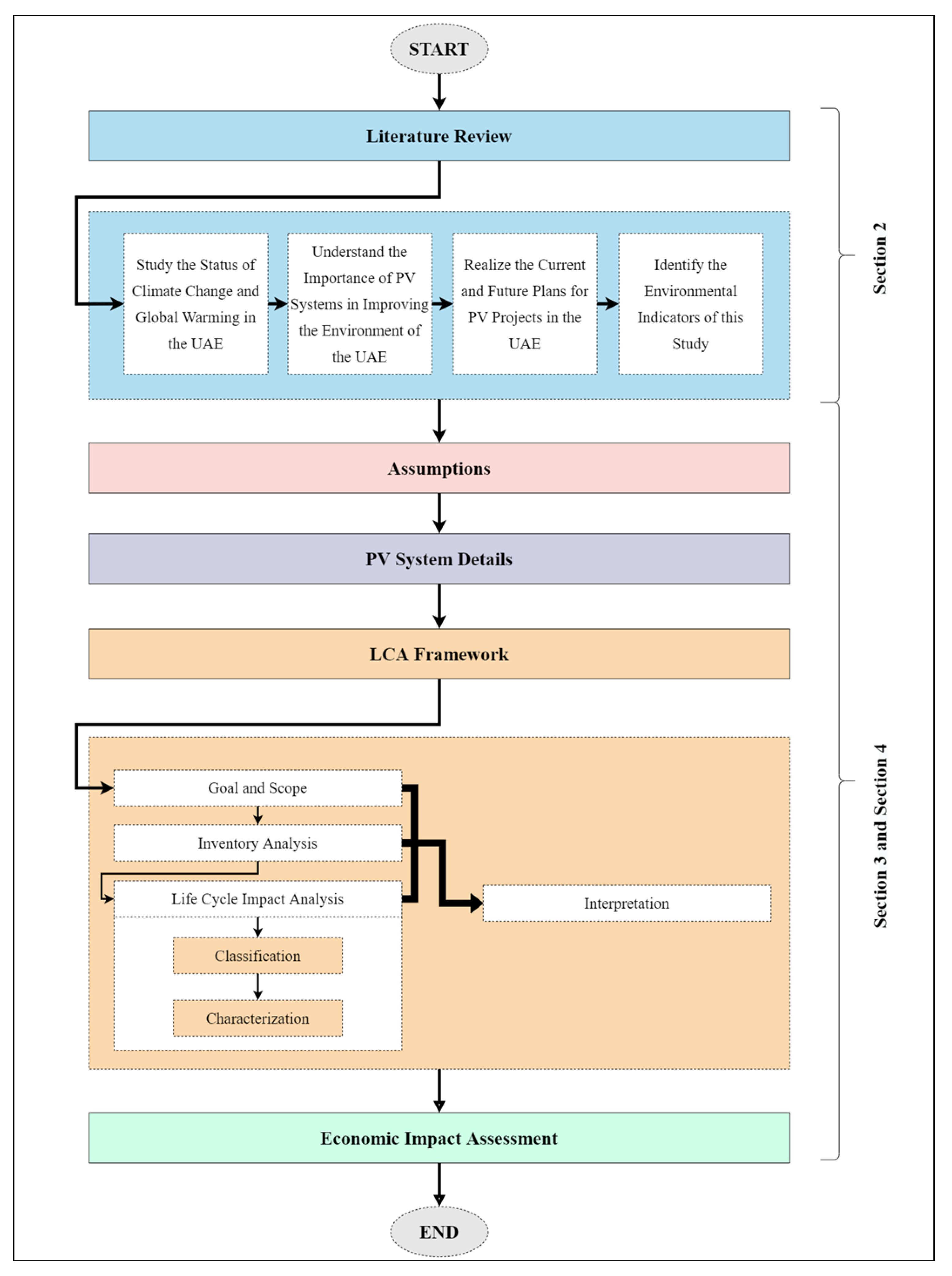
The methodology of this study was built based on the reviewed literature to identify the environmental and economic impacts to be considered, as some of the research questions were answered by the literature. Therefore, the methodology began with reviewing some of the previously conducted studies, then a set of sequential steps that included defining the assumptions of this study, providing details about the PV system location, type, and components, building the LCA framework, and conducting an economic impact assessment for the selected PV system were followed, as illustrated in Figure 2.

3.1. Assumptions

The following subsections represent the main assumptions that this study is based on.

3.1.1. System Boundary

Several cut-off criteria can be used to define the system boundaries and determine what are the included or excluded processes. In this study, the contribution of processes to the environmental impact and availability of data were used as cut-off criteria. Accordingly, the considered processes in this LCA study included the production of PV panel components, the production and assembly of PV panels, the transportation from the manufacturing plant to the site where the system will be installed, which was assumed to be one way (from the manufacturing plant in Amman, Jordan to the industrial facility in Dubai, UAE), the installation process, and the operation process, where the production of PV panels proved its significance in such assessment methods [57].
Additionally, the operation process was assumed to have insignificant environmental impacts as the resources (inputs) and emissions/wastes (outputs) are negligible in this phase when they are compared to the associated production phases; thus, the system was assumed to have zero discharges during the operation phase, while the installation phase was attributed to mounting the aluminum frame and PV panel on the roof and the electrical installation of the inverter and electrical components, where the emissions to air as well as solid wastes were estimated [36,46,88].
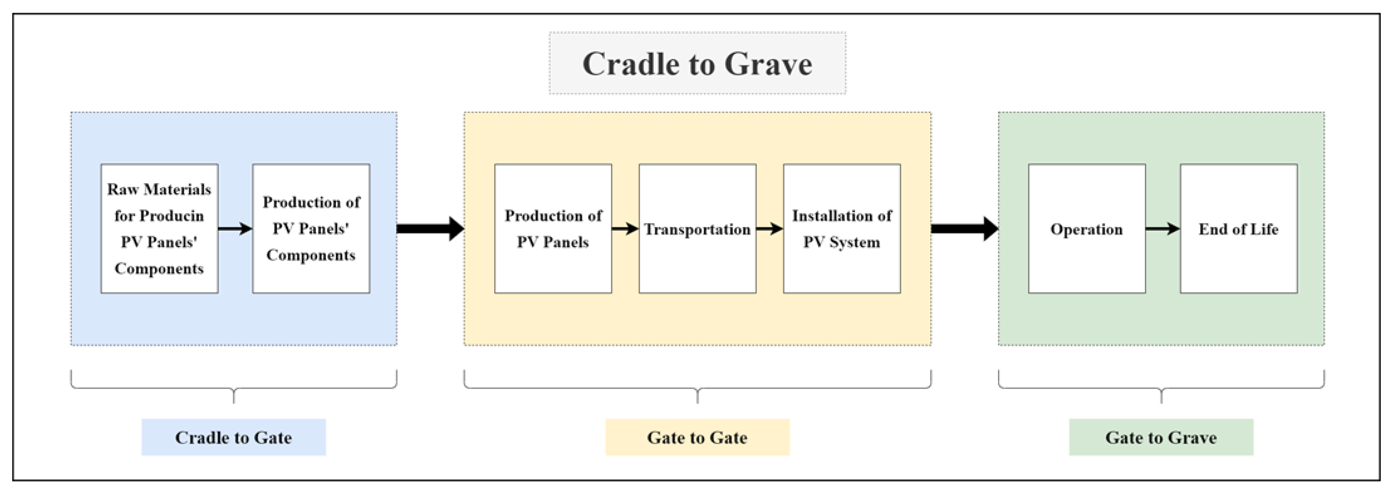
The excluded processes in this study were as follows. (i) Recycling and decommissioning, as the UAE has recently started adopting PV grid-connected systems, and regulations were announced in 2014. Therefore, for such systems, the lifetime is 25–30 years. Currently, there is no information or useful details regarding the recycling or decommissioning processes for PV systems in the UAE. However, the government has set targets for sustainability, and recycling in general that are related to sustainability and a circular economy, which is now taking place in several sectors. However, regarding the PV system, none of the currently installed PV systems have been operating for their whole lifetime, which justifies the lack of relevant information about the recycling system. Additionally, other countries have adopted several recycling/reusing methods for PV panels such as using the aluminum frames for newly produced panels or using the glass for facades. (ii) The maintenance process, as for such types of installation on an included roof, requires minimal maintenance and has almost no environmental impacts; the dust will not accumulate on the panels due to gravity, which implies that frequent cleaning is not required; in addition, the production and performance warranties of the PV panels equal the project lifetime (no replacement required). (iii) Balance of system components (BOS), as their contribution to environmental impacts of a PV system are insignificant compared to PV panels, especially for rooftop projects [36]. BOS includes mounting structures, cables (earthing, AC, and DC), inverters, breakers, and connectors [89]. Figure 3 shows the system boundary for this study.

3.1.2. Function Unit

The function unit is the unit that makes the studies comparable, and it is crucial to define the function unit when conducting a comparative analysis [90]. For this study, the function unit was one polycrystalline PV panel that had a power capacity of 330 Wp and a mass of 22.16 kg.

3.1.3. Project Site

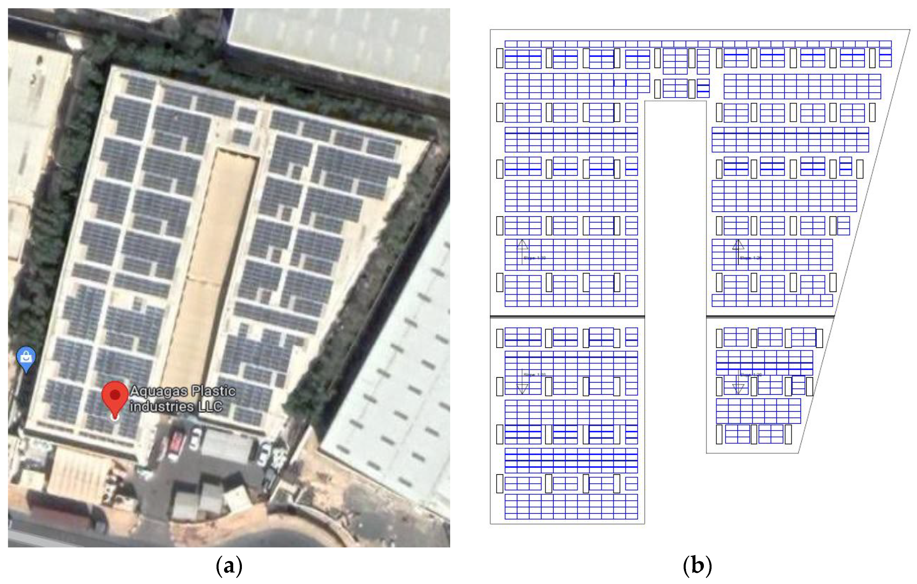
The PV system is installed on the rooftop of an industrial facility in Dubai, UAE. The facility is located in the Dubai Investment Park (DIP), as illustrated in Figure 4, which shows the top-view of the installed PV panels and the distribution of the PV panels on the roof as per the as-built drawings, with a latitude of 24.98°N and a longitude of 55.18°E. In this system, 1080 PV panels are connected to the grid of Dubai (DEWA) to generate electricity from the Sun. Their total mass is 23,932.8 kg, where the front glass component contributes to approximately 68% of the total mass of the PV panels. The area utilized by the PV panels is 1848.75 m2.

3.1.4. Installation Type

The PV system is mounted directly on the rooftop of the facility, having the same orientation as the corrugated sheets that are already installed on the rooftop. This type of installation has many advantages such as assuring the best utilization of the available area with the panels; providing a heat-insulation layer on the roof, which positively impacts the consumption of the air conditioning unit and reduces the associated negative environmental impacts; avoids the use of harmful materials and processes to the environment such as galvanized steel, concrete foundation, and excavation is not used; and a lower initial cost than other types of installation such as ground-mounted PV systems, elevated PV systems, or car parking PV systems.

3.2. PV System Details

The details of the selected PV system include the system components, the contribution of each raw material in the production of the PV panels, and the technical characteristics of the selected PV panel.

3.2.1. System Components

The PV system components consisted of PV panels and BOS, where the latter included all other equipment, except for PV panels, such as inverters, cables, mounting structures, electrical breakers, AC distribution boards, etc. [38]. Table 3 summarizes the components of the PV system considered in this study.

3.2.2. Raw Materials for Producing PV Panels

Since the production of PV panels was the considered production process in this study, as stated in the assumptions, it is important to show the contribution of each raw material in the production of PV panels. Table 4 shows all the raw materials along with their weight in the production of the selected PV panel, where the weight of each PV panel was 22.16 kg. This flow of materials to produce PV panels was defined as the reference flow, which measures the materials needed to define the function unit. These materials will be discussed in more detail in the life cycle inventory section.

3.2.3. Technical Characteristics of the PV panel

The selected PV panel was made of 72 cells of polycrystalline silicon, where 1080 PV panels were installed in this system to make a total installed capacity of 356.4 kWp. Table 5 summarizes the electrical, physical, thermal, material, and other characteristics. The electrical characteristics were measured at controlled testing conditions that are known as standard test conditions (STC) [91] and include (i) irradiance of 1000 W/m2, (ii) ambient temperature of 25 °C, and (iii) air mass of 1.5. The electrical characteristics of the PV panels are given based on these controlled conditions.
The LCA framework consists of four steps, as shown in Figure 1 [28,29]. The goal of this study was to evaluate the environmental impact of the defined function unit installed on a rooftop of an industrial facility in Dubai, UAE, while all of the processes were defined and modeled along with their inputs and outputs to calculate the life cycle inventory (LCI) in the inventory analysis step. Appendix A shows the list of flows with thee inputs and outputs for the production processes for the selected PV panel.
Next, the results from the LCI were used to calculate the life cycle impact assessment (LCIA), where the significance and amount of the potential environmental impact of the processes were defined. It is mandatory to classify the emissions by assigning each to the related impact category and then characterizing the emissions by converting them to a reference unit of measurement using a pre-defined characterization factor [28,29]. In this study, TRACI 2.1 was used for the characterization factors. Finally, the interpretation takes place in the environmental hotspots and draws conclusions and recommendations.
Gabi software was used to conduct this LCA based on the collected information on all the considered processes. However, all the environmental impact factors can be calculated using defined mathematical equations that are related to the assigned emissions for each impact factor.

4. Results

The following subsections summarize the results of the environmental and economic impact assessments.

4.1. Environmental Impact Assessment

The results of the analysis for each environmental indicator are discussed in the following subsections.

4.1.1. Primary Energy Demand, EPBT, and CO2PBT

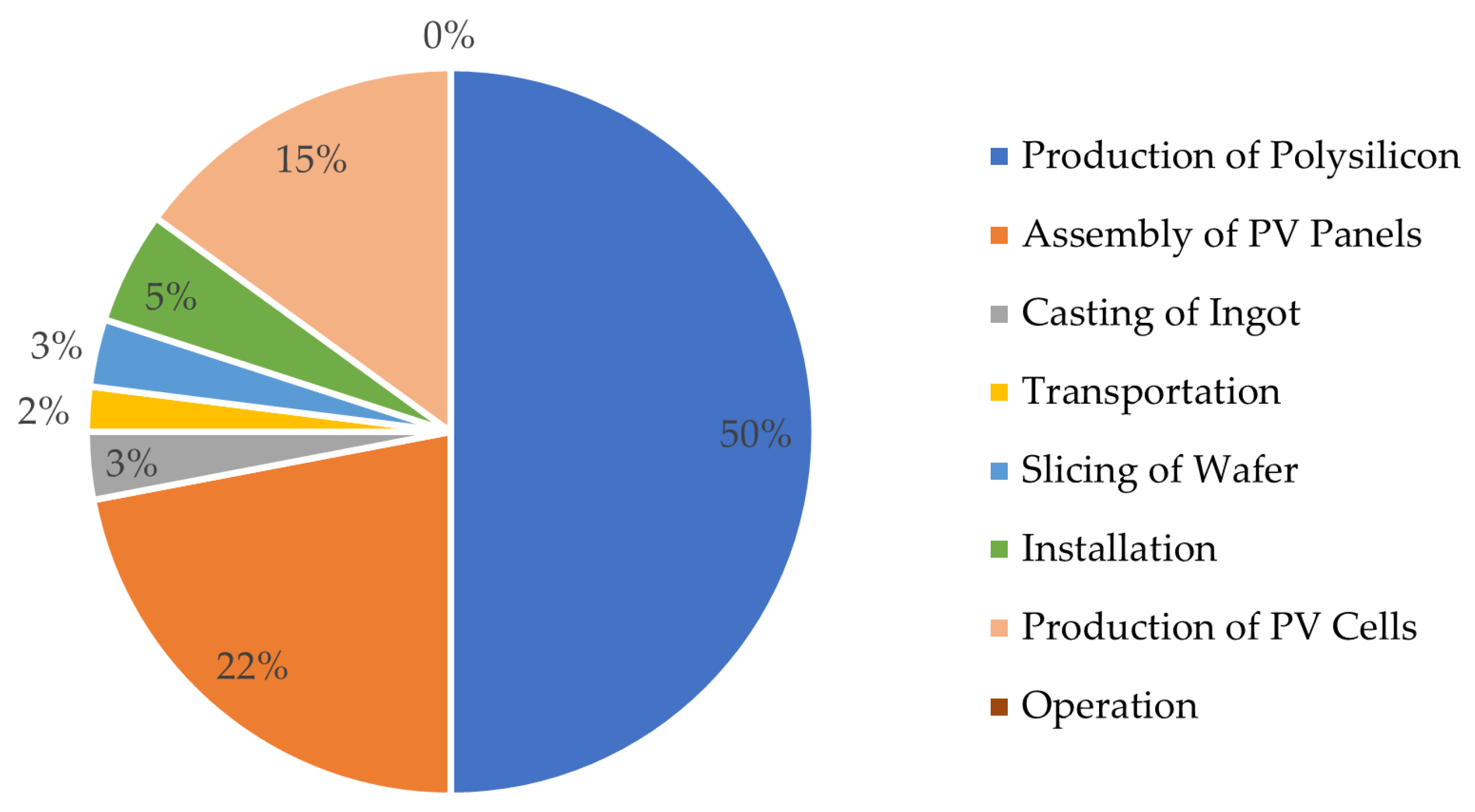
From the analysis, it was found that the production process of polysilicon contributed to approximately 50% of the total primary energy demand, followed by the production process of a PV panel and the production process of PV cells, while other processes had an insignificant contribution to the total primary energy, as shown in Figure 5. The performance ratio of this PV system, which was measured by considering the heat, cables, soiling, and inverter losses, is 75.04%, while the peak sunshine hours in the UAE is approximately 5.84 h/day, the lifetime of the PV system is 25 years, and using the total primary energy required for the whole PV system of 1,151,690.5 kWh (1152 MWh), the EPBT will be 2.15 years, which implies that 2.15 years are needed to recover the energy consumed in the PV system during its lifetime (25 years). In other words, the energy produced from the PV system for the remaining years (22.85 years) is free. Moreover, the calculated CO2PBT was 1.87 years, which means that 1.87 years are needed to recover the CO2 emissions of this PV system by the reduction of CO2 emissions gained from the operation phase of the system.

4.1.2. Global Warming Potential (GWP)

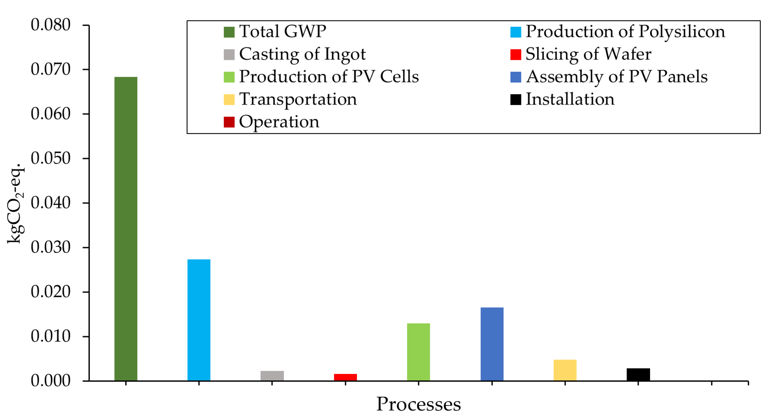
The GWP of this PV system was 6.83 × 10⁻² kg CO2-eq, where the production process of polysilicon contributed to approximately 40% of the total GWP, followed by the production process of a PV panel and the production process of PV cells. These production processes depend on electrical energy from the grid, where conventional energy resources are used to generate and supply electricity. In addition, the production process of the aluminum frame of PV panels is attributed with an abundant amount of CO2 emissions, which justifies the remarkable contribution of these production processes to the GWP. Figure 6 represents the GWP for each process within the defined system boundary.

4.1.3. Acidification Potential (AP)

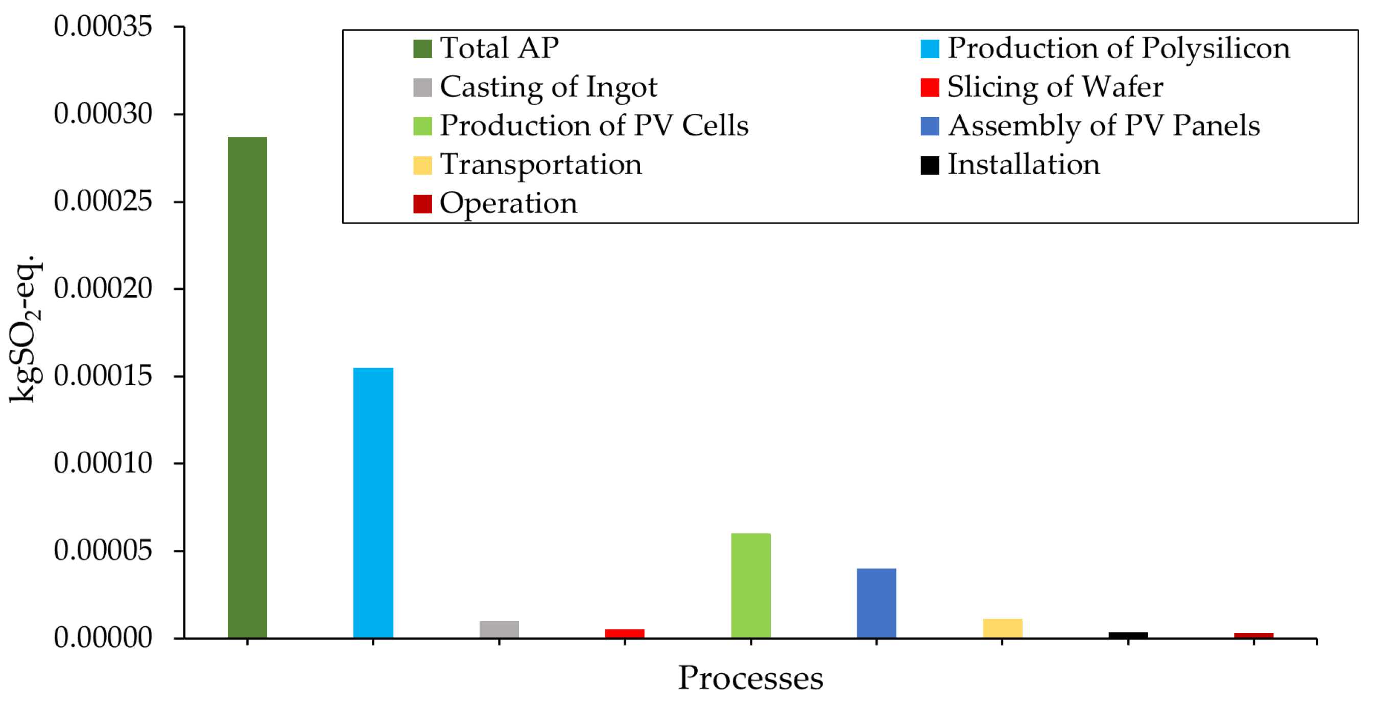
The AP score for this PV system was 2.87 × 10⁻⁴ kg SO2-eq, where the production process of polysilicon contributed to more than 50% of the total calculated AP, followed by the production process of PV cells and the production process of a PV panel. As is the case of the calculated GWP, the contribution of the consumed electricity in the production processes led to this result, as it depends mainly on non-renewable energy resources. Figure 7 illustrates the AP score for each process within the defined system boundary.

4.1.4. Eutrophication Potential (EP)

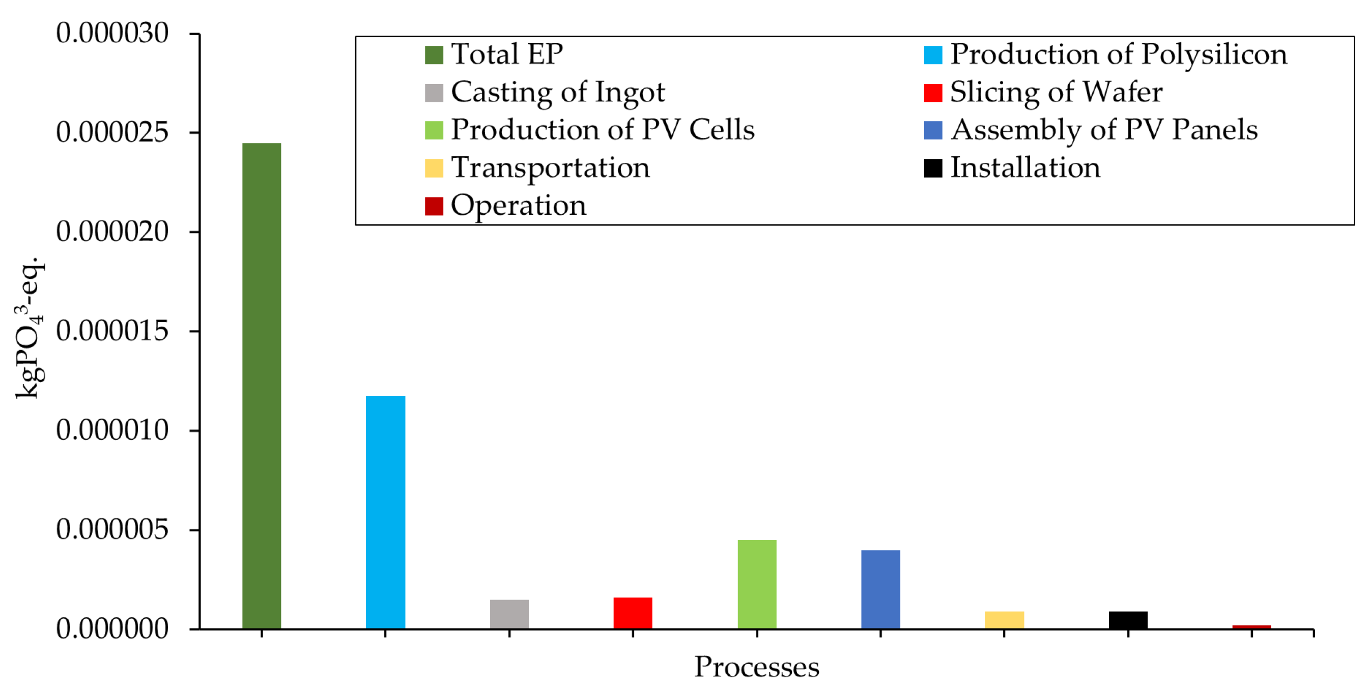
The EP score for this PV system was 2.45 × 10⁻⁵ kg PO43-eq., where the contribution of the processes was similar to the case of AP, the production process of polysilicon contributed to more than 45% of the total calculated AP, followed by the production process of PV cells and the production process of a PV panel. Figure 8 illustrates the EP score for each process within the defined system boundary.

4.1.5. Ozone Layer Depletion Potential (ODP)

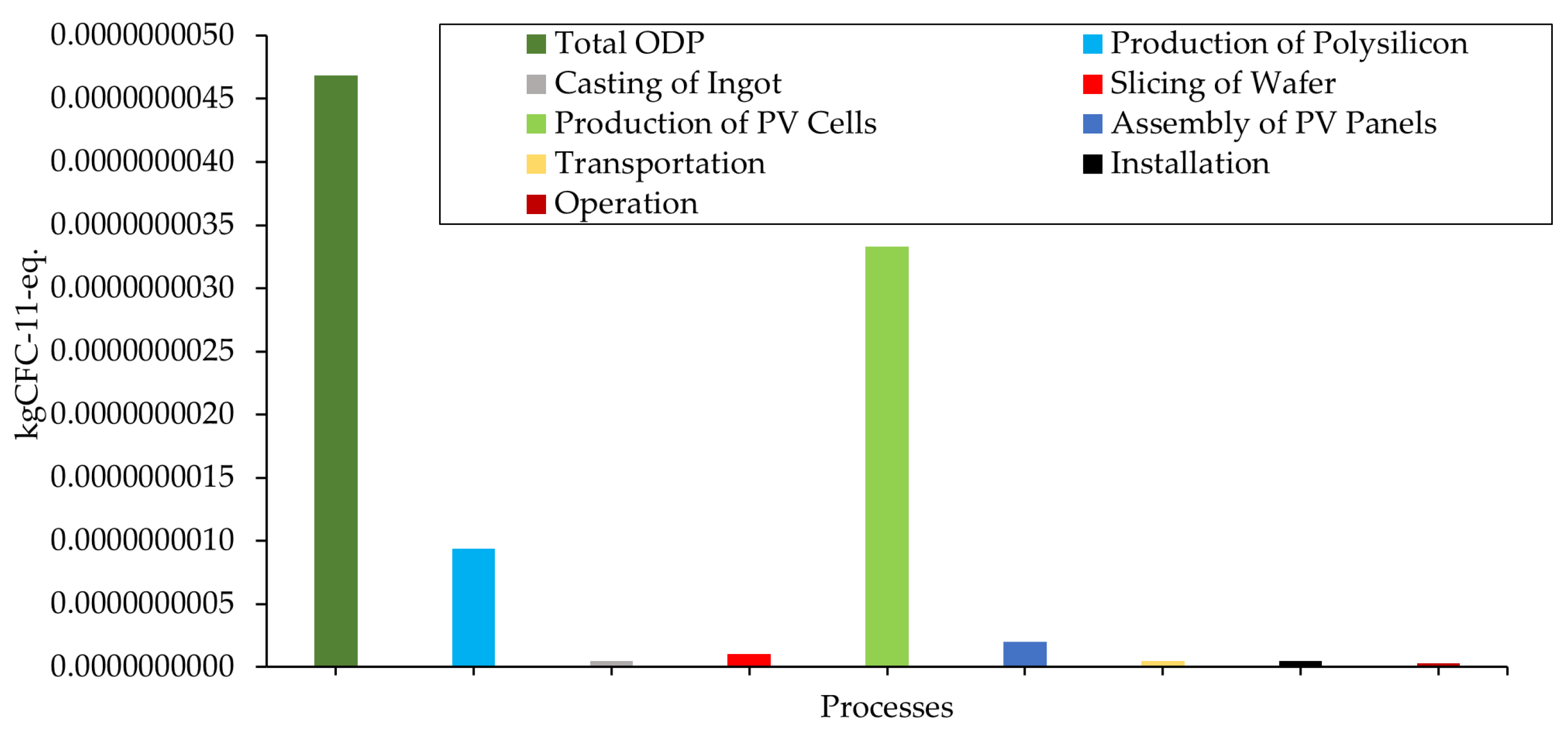
The ODP score for this system was 4.685 × 10⁻⁹ kg CFC-11-eq., the most influential process in this score was the production of a PV panel, which contributed to more than 70% of the total ODP score, followed by the production process of polysilicon, which contributed to approximately 20% of the total ODP, while other processes had an insignificant impact. This was mainly due to the production process for the aluminum frame of the PV panel and the consumed electricity during the whole production process, which is originally generated from non-renewable energy resources. Figure 9 represents the ODP score for each process within the defined system boundary.

4.1.6. Photochemical Ozone Creation Potential (POCP)

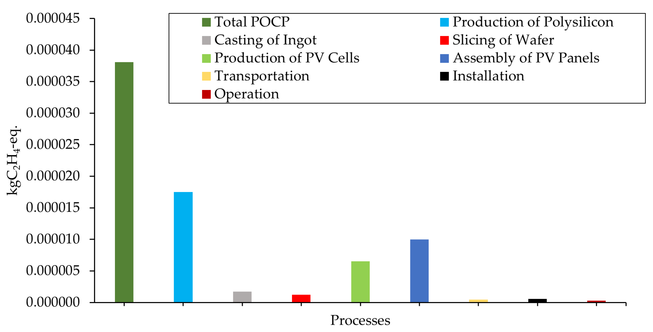
The POCP score for this system was 3.81 × 10⁻⁵ kg C2H4-eq., similar to most of the discussed environmental indicators. The production of polysilicon, PV cells, and the PV panel were the most influential processes in the total POCP score. This was due to the non-renewable source of electricity at the production plants and the aluminum frame production process. Figure 10 shows the POCP score for each process within the defined system boundary.

4.1.7. Human Toxicity Potential (HTP)

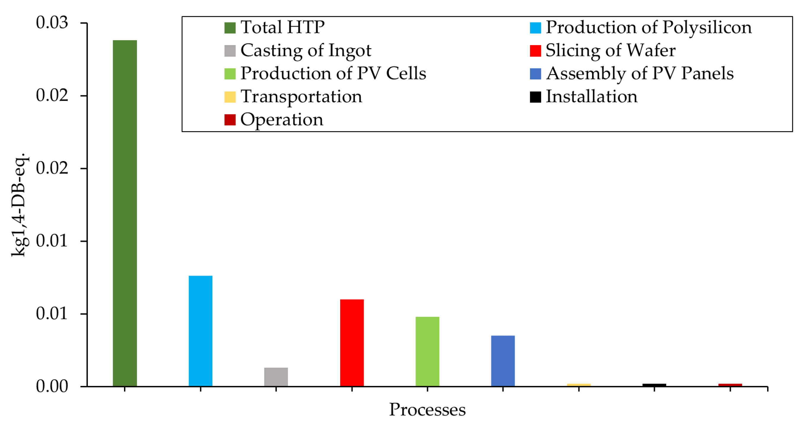
The HTP score for this system was 2.38 × 10⁻² kg 1,4-DB-eq., where the production of polysilicon was responsible for more than 30% of this score, followed by the slicing process of the wafer with approximately 25%, and the production of PV panels with approximately 20%, while each one of the remaining processes had an insignificant contribution, as illustrated in Figure 11.

4.2. Economic Impact Assessment

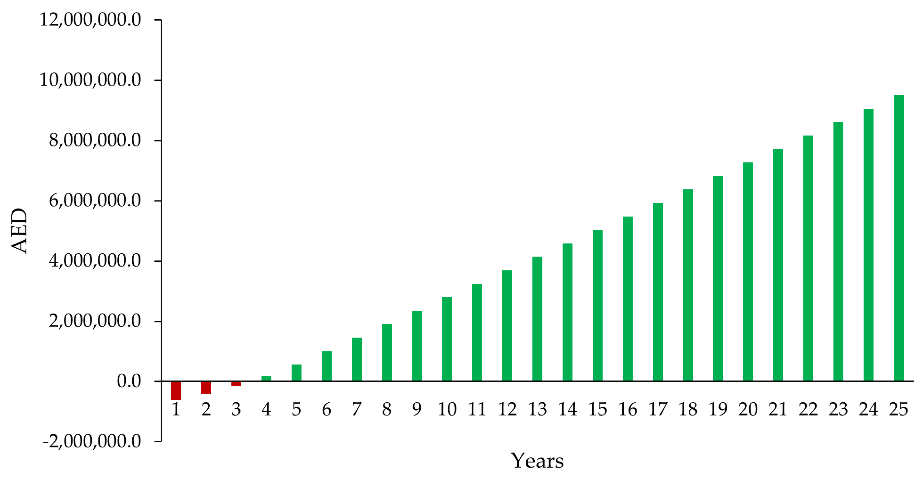
Considering the electricity consumption for the facility before installing the PV system, the electricity tariff for the industrial sector in Dubai is DEWA (Dubai Electricity and Water Authority) and including the additional charges (value-added tax and fuel charges) [92], the discount rate (%), and the projected generation of the PV system based on the estimated losses during the operation, and the degradation in the performance of the PV panels, Table 6 can be constructed, and the achieved monetary savings (AED) considering all of the incurred costs during the project lifetime will equal AED 10,520,372 at the end of the PV project’s life.
Using the aforementioned economic metrics, the LCOE for this project can be calculated using the following equation [59,60]. The LCOE equals 0.142 AED/kWh, which is ~31.4% of the current industrial tariff at DEWA (0.452 AED/kWh), indicating the high economic feasibility of the project.
LCOE = i = 0 N I i + O i + F i TC i 1 + r i i = 0 N E i 1 + r i
I i is the capital cost in year i (currency). O i is the operation and maintenance cost in year i (currency). F i is the cost of used fuel in year i (currency). TC i is the tax credits or insurance cost on year i (currency). R is the considered discount rate (%). E i is the generated electricity from the PV system in year i (kWh). N is the economic lifetime of the PV system (years).
The BCR can be calculated by dividing the net present value of the net positive cashflow by the net present value of the net negative cashflow [59,60], as shown in the following equation. The BCR equals 11.8, and since it is greater than 1, it indicates a high feasibility and profitability.
BCR = NPV net   positive   cashflow NPV net   negative   cashflow
Finally, the payback period can be calculated using the following equation [59,60]. The PBP of this PV project was 3.5 years, which was 14% of the project lifetime, as illustrated in Figure 12.
PBP = NPV net   positive   cashflow NPV net   negative   cashflow
Additionally, installing PV panels on such types of roofs is considered the most feasible option, as the required structure for installing the panels is the least among other types of installation. In this installation, the panels are laid on the corrugated sheet by using aluminum rails that are fixed on the roof through and linked to the existing rails that carry the corrugated sheet. Therefore, the capital cost is significantly reduced, which results in improving the feasibility of the project. However, there is a limit on the size of the PV system where below this limit the system would be feasible. Setting this limit takes into consideration several vital factors including the average electrical consumption, the associated maintenance, the available area for installation, cost per kWp installed, etc. For this PV system, the installed size is 356.4 kWp in terms of the maximum capacity that can be installed on the roof area considering empty spaces for access, cleaning, and maintenance. However, installing a PV system that is less than 185 kWp for this project would be unfeasible, as the LCOE will be higher than the prevailing tariff (AED/kWh), would cover less than 40% of the consumption, and increase the payback period by an additional 5 years. In terms of the environmental effects, previous studies suggested that PV systems are defined as emission-free energy systems [93], and the adverse environmental impacts are usually linked to the production processes regardless of the system size.

5. Discussion

The study revealed that the main environmental damage due to PV panels occurred during the production processes of polysilicon, PV cells, and PV panels due to the high-demand on-grid electricity that is generated from non-renewable resources as well as the associated greenhouse gas emissions from producing the polysilicon material, slicing the wafers, producing the aluminum frames, and assembling the panels. Based on the results in Section 4, it was noticed that all of the considered environmental impact indicators have been examined for the processes within the defined system boundary. Each indicator has shown significance based on the emissions resulting from each flow. The total primary energy demand in this study was mainly through the use of grid electricity, which is derived from conventional/non-renewable energy resources and mostly incurred in the production of polysilicon, PV cells, and PV panels. Therefore, optimizing the production processes will result in better primary energy demand values, which will accordingly decrease the energy payback time. This has also been highlighted by [44], where the impact of optimizing the production processes and providing PV panels with higher efficiency would certainly result in lower energy payback times.
Similarly, these production processes contribute to most of the global warming potential, acidification potential, eutrophication potential, human toxicity potential, ozone layer depletion potential, and photochemical ozone creation potential. This is attributed to carbon dioxide, sulfur dioxide, nitrate, nitrogen oxides, nitrous oxide, ammonia, silicon tetrachloride, phosphate, non-methane volatile organic compounds (NMVOC), selenium, and other greenhouse gas emission from the high demand on electricity (grid) in production processes. These findings are in line with the findings in similar studies in Korea, Thailand, and China [23,36,44,56,59,61,94,95,96,97]. For example, the production of ultrapure silicon has a high energetic cost and releases chlorinated gases to the atmosphere, which results in adverse environmental consequences [98].
However, the operation phase has a negligible environmental impact on the selected PV system, as shown in the Results section, which is supported by a few previously conducted studies where the contribution of the operation phase was found to be insignificant in the overall impact assessment indicators [36,46,88].
When assessing the influence of transportation of the PV panels, it has been shown that the impact could be considered insignificant as the panels used in this study were transported from Jordan to the UAE through land freight, which has a considerably lower negative impact on the environment and cost compared to other exporting destinations such as China, Europe, or the USA. These findings are highly influenced by the geographical location, installation type, materials used, the origin of the materials, etc.
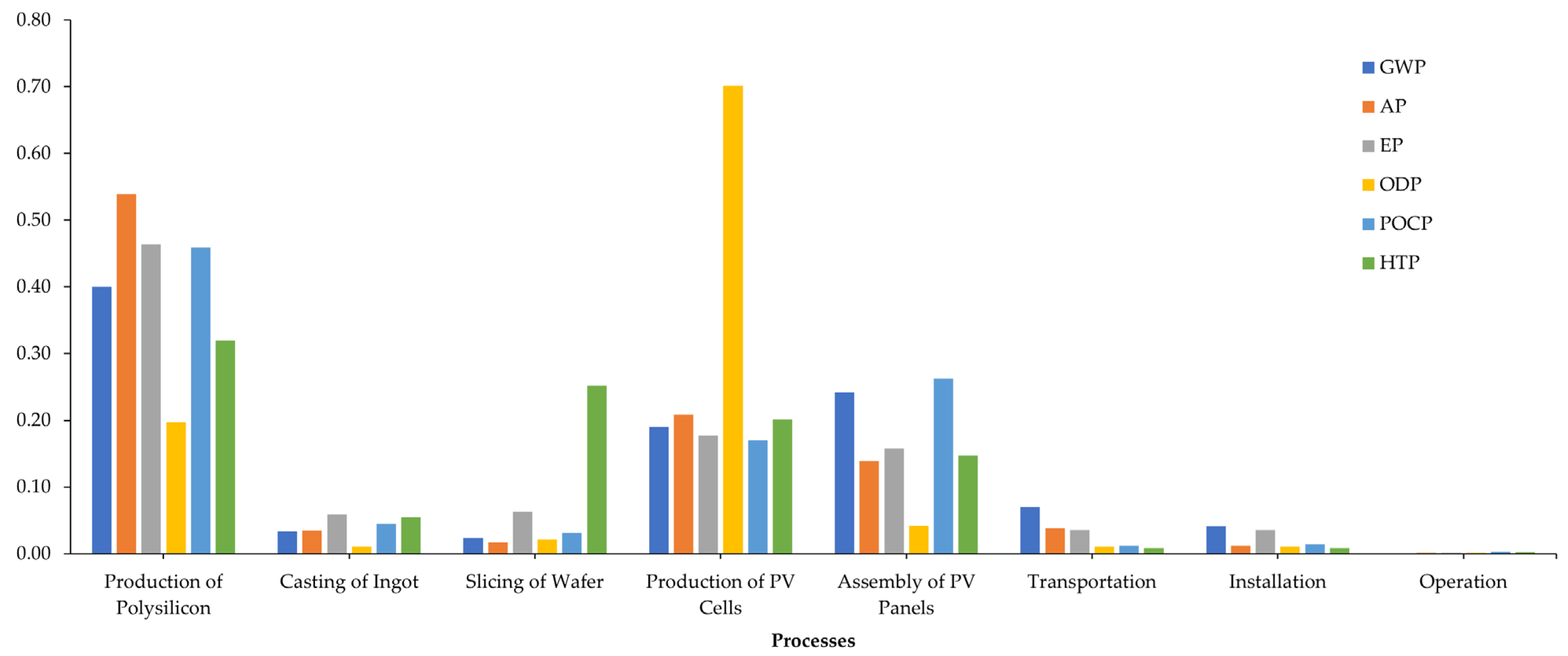
Furthermore, a comparison of the findings for all of the selected environmental impacts was conducted to highlight the significance of each environmental indicator in each process. This was carried out by normalizing the results for all indicators and then comparing them across all of the processes. Figure 13 shows the normalized environmental impacts for the considered processes of the function unit, where it can be noticed that the environmental impact indicators for the operation phase were negligible, while the installation, transportation, slicing of the wafer, and casting of ingots had a small influence on the selected environmental impacts. However, the production of polysilicon, PV cells, and PV panels had the most significant influence on the environmental impacts, where they contributed to 83.5% of the total GWP, 91% of the total AP, 84.5% of the total EP, 95% of the total ODP, 92.3% of the total POCP, and 69.8% of the total HTP.
Regarding the economic impact of this PV system, it can be noticed from the results that the selected economic indicators showed high profitability and feasibility values, where for such a long project lifetime (25 years), the capital investment cost including the material, installation, and operation costs will be recovered within 3.5 years of operation, which promotes adopting PV systems to generate electricity in the UAE. Moreover, with the anticipated increase in the grid electricity tariff, the PBP would be less than 3.5 years. Additionally, the benefit-to-cost ratio for this project was calculated based on the net present value (positive and negative) and resulted in a high value of 11.8, which implies a profitable project. Finally, the levelized cost of electricity was 0.142 AED/kWh, while the current electricity tariff in DEWA for the industrial sector is 0.452 AED/kWh. It is apparent from the results that generating electricity from the PV system is definitely more feasible than relying on the grid, even though the dependence on the PV system is partly due to area limitations that would restrict installing a PV system that covers all of the consumption. These findings were based on comparing the electricity generated from the system with the electricity withdrawn from the grid, so the results would differ and become more feasible if they are compared with other sources of electricity such as diesel generators that are used on several islands and remote areas in the UAE.
The recycling phase is not yet implemented or regulated in the UAE, as the market of PV is still new (not more than 6 years), but it is important to explore the dismantling, recycling, decommissioning, or reusing practices of PV panels and be ready with proper procedures that would not impact the environment negatively. A study by Bartie et al. (2021) explored the PV life cycles in terms of resource efficiency, circularity, and sustainability, presenting potential opportunities for the recovery of high-quality secondary resources [99]. Additionally, other studies have suggested the use of emerging materials and technologies to improve the use of solar energy. The study focused on enhancing the efficiency of photovoltaic devices such as hot-carrier solar cells, printable solar cell materials, multijunction, ultrathin, and intermediate band [100].
Additionally, the social aspect can be integrated into this sustainability assessment by conducting a qualitative study based on a representative survey using several social indicators such as job creation, human health, human welfare, ethic, awareness, and social acceptance, where the results will provide recommendations and suggestions to weak areas where the efforts should be focused to enhance the social sustainability of the PV project.
In general, the adaptation of renewable energy sources such as solar energy is a promising field, but its effects on the environment, especially at the production stage, should be carefully assessed to ensure minimal environmental impacts.

6. Conclusions

The UAE has announced its net zero strategy initiative in hopes of achieving net-zero emissions by 2050. As part of this initiative, solar energy dominates due to its regional potential. This study used a case study in Dubai and provides comprehensive environmental and economic impact assessments of a PV project considering a polycrystalline PV panel (330 Wp) as a function unit, where the production of raw materials, the production of PV cells, the production of PV panels, the transportation of PV panels from Jordan to Dubai, UAE, installation of the PV system, and the operation of the system were the included processes within the system boundary. It is clear that the main impacts to the environment from the PV panels are during their production, rather than their usage.
The findings of this study open the door to encouraging policymakers, PV manufacturing plants, and PV contracting companies to optimize the associated processes used for the production of the panels to enhance the sustainability of PV systems. Hence, it is recommended that the production processes, especially for the silicon, cells, frames, and panels, are optimized as well as incorporating renewable energy resources in their production plants to decrease the dependency on grid electricity.

Author Contributions

Conceptualization, H.A. and F.S.; Methodology, H.A.; Software, H.A.; Validation, H.A. and F.S.; Formal analysis, H.A.; Investigation, H.A. and F.S.; Resources, H.A. and F.S.; Data curation, H.A.; Writing—original draft preparation, H.A.; Writing—review and editing, H.A. and Fatin Samara; Visualization H.A.; Supervision, F.S.; Project administration, H.A. All authors have read and agreed to the published version of the manuscript.

Funding

This research received no external funding.

Data Availability Statement

Data supporting the reported results can be found in Appendix A.

Acknowledgments

The authors acknowledge the superior technical support of the Philadelphia Solar L.L.C., Jordan and Aquagas Plastic Industries L.L.C., UAE in providing the required data for the analysis part of this study as well as the American University of Sharjah for their support during the study. The authors are thankful for the enhancing comments and suggestions by the referees and the Editor. Their comments and suggestions have greatly enhanced the manuscript.

Conflicts of Interest

The authors declare no conflict of interest.

Appendix A

Table A1. Flows for the production processes of the selected 330 Wp polycrystalline PV panel.
No.ProcessesUnitValue
1Metallurgical Smelting for Silicon
1.1Inputs
1.1.1Standard Coalkg14.85
1.1.2Quartz Sandkg6.37
1.1.3Graphitekg0.22
1.1.4Tarkg0.22
1.1.5ElectricitykWh23.73
1.1.6Waterkg23.73
1.2Outputs
1.2.1Siliconkg1.86
1.2.2Slag from MG Silicon Production for Disposalkg1.39
1.2.3Suspended Substanceskg0.06
1.2.4Carbon Dioxide to Airkg41.95
1.2.5Carbon Monoxide to Airkg0.77
1.2.6Nitrogen Oxides to Airg86.79
1.2.7Silicon Dioxide to Airkg0.52
1.2.8Sulfur Dioxide to Airkg0.21
1.2.9Waterkg23.10
2Production of Polysilicon
2.1Inputs
2.1.1Trichlorosilanekg9.81
2.1.2Metallurgical Siliconkg1.87
2.1.3Silicon Tetrachloridekg2.60
2.1.4Calcium Oxidekg2.09
2.1.5Hydrogenkg0.17
2.1.6Hydrofluoric Acidkg0.02
2.1.7Hydrochloric Acidkg1.07
2.1.8Chlorinekg1.94
2.1.9Nitric Acidkg0.08
2.1.10Nitrogen Gaseouskg23.00
2.1.11Sodium Hydroxidekg1.40
2.1.12ElectricityMJ666.12
2.1.13Steamkg108.55
2.1.14Waterkg2794.04
2.2Outputs
2.2.1Solar Grade Poly Siliconkg1.79
2.2.2Silicon Dust for Recoverykg0.29
2.2.3COD to Waterg25.23
2.2.4Suspended Solids to Freshwaterg16.75
2.2.5Silicakg1.65
2.2.6Chloridekg1.95
2.2.7Trichlorosilane to Airg9.57
2.2.8Chlorosilane to Airg8.42
2.2.9Water (Evapotranspiration) to Airkg2021.91
2.2.10Hydrogen Chloride to Airg10.09
2.2.11Hydrogen Fluoride to Airg0.05
2.2.12Silicon Tetrachloride to Airg2.69
2.2.14Silicon Dust to Airg2.45
2.2.15Nitrogen Dioxide to Airg1.13
3Casting of Ingot
3.1Inputs
3.1.1Solar Grade Poly Siliconkg1.79
3.1.2Quartz Cruciblekg5.04
3.1.3Silicon Carbideg20.08
3.1.4Sodium Hydroxideg15.01
3.1.5Argonkg3.66
3.1.6Silicon Chloridekgsilicon chloride
3.1.7Compressed Airm36.11
3.1.8Hydrofluoric Acidg61.67
3.1.9Hydrochloric acidkg0.94
3.1.10ElectricityMJ53.29
3.1.11Steamkg2.61
3.1.12Waterkg143.82
3.2Outputs
3.2.1Poly Silicon Ingotkg1.71
3.2.2Waste Quartz Crucible for Recoverykg5.04
3.2.3Silicon Carbideg19.65
3.2.4Waste Acidg107.48
3.2.5Water (Evapotranspiration) to Airkg118.29
3.2.6Hydrogen Fluoride to Airg0.20
4Slicing of Wafer
4.1Inputs
4.1.1Poly Silicon ingotkg1.71
4.1.2Steel Wirekg5.32
4.1.3Glasskg0.83
4.1.4Compressed Airm38.87
4.1.5Detergentkg0.70
4.1.6Silicon Carbideg55.85
4.1.7Acetic Acidkg0.20
4.1.8ElectricityMJ7.35
4.1.9Waterkg156.68
4.2Outputs
4.2.1Poly Silicon Waferkg1.05
4.2.2Silicon Scrap for Recoverykg0.61
4.2.3Glue Residues for Disposalg75.09
4.2.4Glasskg0.83
4.2.5Chlorideg1.98
4.2.6Hydrogen Chlorideg0.09
4.2.7Nitrogen Oxides to Airg0.35
4.2.8Acetic Acidkg0.20
4.2.9Wastewaterkg98.00
5Production of PV Cells
5.1Inputs
5.1.1Poly Silicon Waferkg1.05
5.1.2Natural Gaskg0.17
5.1.3KOHkg0.82
5.1.4Nitrogenkg2.28
5.1.5Nitric Acidkg0.74
5.1.6Phosphoric Acidg3.14
5.1.7Hydrofluoric Acidkg0.19
5.1.8Hydrochloric Acidkg0.78
5.1.9Ammoniag28.36
5.1.10Aluminumkg0.16
5.1.11Silverg18.14
5.1.12Ethanolkg0.08
5.1.13ElectricityMJ189.64
5.1.14Steamkg8.74
5.1.15Waterkg281.14
5.2Outputs
5.2.1Poly Silicon Solar CellkW0.33
5.2.2NMVOC to Airg10.52
5.2.3Nitrogen Oxides to Airg22.56
5.2.4Hydrogen Fluoride to Airg1.30
5.2.5Hydrogen Chloride to Airg1.50
5.2.6Ammonia to Airg2.26
5.2.7Waterkg287.97
6Assembly of a PV Panel
6.1Inputs
6.1.1Poly Silicon Solar CellkW0.33
6.1.2Aluminumkg4.46
6.1.3Glasskg15.1
6.1.4Isopropanolg5.24
6.1.5Ethylene Vinyl Acetate Copolymer (EVA)kg2.30
6.1.6Ethanolg17.69
6.1.7Poly-Vinyl Fluoride Film (PVF)kg0.97
6.1.8Poly-Ethylene Terephthalate (PET)kg0.97
6.1.9ElectricityMJ23.08
6.1.10Steamkg5.22
6.1.11Waterkg38.99
6.2Outputs
6.2.1PV Solar PanelskW0.33
6.2.2Suspended Substanceskg0.13
6.2.3Activated Carbon for Recoveryg19.87
6.2.4Carbon Dioxideg205.59
6.2.5Water (Evapotranspiration) to Airkg31.11
6.2.6Water to Freshwaterkg7.53

References

  1. Enerdata. Electricity Domestic Consumption. 2020. Available online: https://yearbook.enerdata.net/electricity/electricity-domestic-consumption-data.html (accessed on 20 December 2020).
  2. IEA (International Energy Agency). World Energy Outlook 2011. Available online: https://www.iea.org/ (accessed on 25 December 2020).
  3. Al-Maamary, H.M.; Kazem, H.A.; Chaichan, M.T. The impact of oil price fluctuations on common renewable energies in GCC countries. Renew. Sustain. Energy Rev. 2017, 75, 989–1007. [Google Scholar] [CrossRef]
  4. Prakash, R.; Bhat, I.K. Energy, economics and environmental impacts of renewable energy systems. Renew. Sustain. Energy Rev. 2009, 13, 2716–2721. [Google Scholar]
  5. IEA. International Energy Agency: Renewables 2020. Available online: https://webstore.iea.org/download/direct/4234 (accessed on 20 December 2020).
  6. IRENA. Trends in Renewable Energy. 2020. Available online: https://public.tableau.com/views/IRENARETimeSeries/Charts?:embed=y&:showVizHome=no&publish=yes&:toolbar=no (accessed on 25 May 2021).
  7. IRENA. Trends in Renewable Energy by Region. 2020. Available online: https://www.irena.org/Statistics/View-Data-by-Topic/Capacity-and-Generation/Regional-Trends (accessed on 25 May 2021).
  8. Chu, Y.; Meisen, P. Review and Comparison of Different Solar Energy Technologies; Global Energy Network Institute (GENI): San Diego, CA, USA, 2011. [Google Scholar]
  9. Tyagi, V.; Rahim, N.A.; Rahim, N.; Jeyraj, A.; Selvaraj, L. Progress in solar PV technology: Research and achievement. Renew. Sustain. Energy Rev. 2013, 20, 443–461. [Google Scholar] [CrossRef]
  10. Kazem, H.A. Renewable energy in Oman: Status and future prospects. Renew. Sustain. Energy Rev. 2011, 15, 3465–3469. [Google Scholar] [CrossRef]
  11. Ellabban, O.; Abu-Rub, H.; Blaabjerg, F. Renewable energy resources: Current status, future prospects and their enabling technology. Renew. Sustain. Energy Rev. 2014, 39, 748–764. [Google Scholar] [CrossRef]
  12. Warm-Heart-Worldwide. Climate Change Primer. Available online: https://warmheartworldwide.org/climate-change/?gclid=Cj0KCQjwkZiFBhD9ARIsAGxFX8C6AtIeRU_A2huBrO1-AIGVfBTiiRKFR-OrDN9-J8UqeEwOsDtCqlkaAscLEALw_wcB (accessed on 10 September 2022).
  13. Kweku, D.W.; Bismark, O.; Maxwell, A.; Desmond, K.A.; Danso, K.B.; Oti-Mensah, E.A.; Quachie, A.T.; Adormaa, B.B. Greenhouse effect: Greenhouse gases and their impact on global warming. J. Sci. Res. Rep. 2017, 17, 1–9. [Google Scholar] [CrossRef]
  14. Romero, Y.; Chicchon, N.; Duarte, F.; Noel, J.; Ratti, C.; Nyhan, M. Quantifying and spatial disaggregation of air pollution emissions from ground transportation in a developing country context: Case study for the Lima Metropolitan Area in Peru. Sci. Total Environ. 2020, 698, 134313. [Google Scholar] [CrossRef]
  15. Grossi, G.; Goglio, P.; Vitali, A.; Williams, A.G. Livestock and climate change: Impact of livestock on climate and mitigation strategies. Anim. Front. 2019, 9, 69–76. [Google Scholar] [CrossRef] [Green Version]
  16. C2ES. Global Greenhouse Gas Emissions by Sector. 2017. Available online: https://www.c2es.org/content/international-emissions/#:~:text=Globally%2C%20the%20primary%20sources%20of,72%20percent%20of%20all%20emissions (accessed on 25 May 2021).
  17. Enerdata. United Arab Emirates—Trend over 2000–2019. Available online: https://yearbook.enerdata.net/electricity/electricity-domestic-consumption-data.html (accessed on 23 October 2020).
  18. Enerdata. United Arab Emirates—Renewable—Trend over 2000–2019. Available online: https://yearbook.enerdata.net/renewables/renewable-in-electricity-production-share.html (accessed on 23 October 2020).
  19. United Arab Emirates—Country Commercial Guide. 2020. Available online: https://www.trade.gov/country-commercial-guides/united-arab-emirates-renewable-energy (accessed on 10 September 2022).
  20. Ritchie, H. United Arab Emirates: CO2 Country Profile. 2020. Available online: https://ourworldindata.org/co2/country/united-arab-emirates (accessed on 21 May 2021).
  21. Gao, S.; Bao, J.; Liu, X.; Stenmarck, A. Life cycle assessment on food waste and its application in China. IOP Conf. Ser. Earth Environ. Sci. 2018, 108, 042037. [Google Scholar] [CrossRef]
  22. Hauschild, M.Z.; Rosenbaum, R.K.; Olsen, S.I. Life Cycle Assessment; Springer: Berlin/Heidelberg, Germany, 2018. [Google Scholar]
  23. Van Bueren, E.; Van Bohemen, H.; Visscher, H. Sustainable Urban Environments. An Ecosystems Approach; Springer: Dordrecht, Netherlands, 2012. [Google Scholar]
  24. Galatola, M.; Pant, R. Reply to the editorial “Product environmental footprint—Breakthrough or breakdown for policy implementation of life cycle assessment?” written by Prof. Finkbeiner (Int J Life Cycle Assess 19 (2): 266–271). Int. J. Life Cycle Assess. 2014, 19, 1356–1360. [Google Scholar] [CrossRef]
  25. Meylan, G.; Stauffacher, M.; Krütli, P.; Seidl, R.; Spoerri, A. Identifying Stakeholders’ Views on the Eco-efficiency Assessment of a Municipal Solid Waste Management System: The Case of Swiss Glass-Packaging. J. Ind. Ecol. 2015, 19, 490–503. [Google Scholar] [CrossRef]
  26. Mudgal, S.; Benito, P. Reporting on the implementation of integrated product policy (IPP). Eur. Comm. DG Environment. Serv. Contract 2008, 703307, 481297. [Google Scholar]
  27. Reed, D.L. Life-cycle assessment in government policy in the United States. 2012. Available online: https://trace.tennessee.edu/utk_graddiss/1394/ (accessed on 10 September 2022).
  28. ISO-14040:2006; Environmental Management—Life Cycle Assessment—Principles and Framework. International Organization for Standardization: Geneva, Switzerland, 2006. Available online: https://www.iso.org/standard/37456.html (accessed on 10 September 2022).
  29. ISO-14044:2006; ISO 14044:2006 Environmental Management—Life Cycle Assessment—Requirements and Guidelines. International Organization for Standardization: Geneva, Switzerland, 2006. Available online: https://www.iso.org/standard/38498.htm (accessed on 28 May 2021).
  30. Hunt, L.P. Total energy use in the production of silicon solar cells from raw materials to finished product. In Proceedings of the 12th Photovoltaic Specialists Conference, New York, NY, USA, 15–18 November 1976; pp. 347–352. [Google Scholar]
  31. Kannan, R.; Leong, K.; Osman, R.; Ho, H.; Tso, C. Life cycle assessment study of solar PV systems: An example of a 2.7 kWp distributed solar PV system in Singapore. Sol. Energy 2006, 80, 555–563. [Google Scholar] [CrossRef]
  32. Krauter, S.; Rüther, R. Considerations for the calculation of greenhouse gas reduction by photovoltaic solar energy. Renew. Energy 2004, 29, 345–355. [Google Scholar] [CrossRef]
  33. Zhai, P.; Williams, E.D. Dynamic hybrid life cycle assessment of energy and carbon of multicrystalline silicon photovoltaic systems. Environ. Sci. Technol. 2010, 44, 7950–7955. [Google Scholar] [CrossRef]
  34. Fthenakis, V.M.; Kim, H.C. Life cycle assessment of high-concentration photovoltaic systems. Prog. Photovolt. Res. Appl. 2013, 21, 379–388. [Google Scholar] [CrossRef]
  35. Frischknecht, R.; Itten, R.; Wyss, F.; Blanc, I.; Heath, G.; Raugei, M.; Sinha, P.; Wade, A. Life Cycle Assessment of Future Photovoltaic Electricity Production from Residential-Scale Systems Operated in Europe; National Renewable Energy Lab. (NREL): Golden, CO, USA, 2015.
  36. Fu, Y.; Liu, X.; Yuan, Z. Life-cycle assessment of multi-crystalline photovoltaic (PV) systems in China. J. Clean. Prod. 2015, 86, 180–190. [Google Scholar] [CrossRef]
  37. He, Y. Life Cycle Assessment of Solar-Grade Multi-Crystalline Silicon; Southwest Jiaotong University: Chengdu, China, 2013. (In Chinese) [Google Scholar]
  38. Muteri, V.; Cellura, M.; Curto, D.; Franzitta, V.; Longo, S.; Mistretta, M.; Parisi, M.L. Review on life cycle assessment of solar photovoltaic panels. Energies 2020, 13, 252. [Google Scholar] [CrossRef] [Green Version]
  39. Jungbluth, N. Life cycle assessment of crystalline photovoltaics in the Swiss ecoinvent database. Prog. Photovolt. Res. Appl. 2005, 13, 429–446. [Google Scholar] [CrossRef] [Green Version]
  40. Komoto, K.; Oyama, S.; Sato, T.; Uchida, H. Recycling of PV modules and its environmental impacts. In Proceedings of the 2018 IEEE 7th World Conference on Photovoltaic Energy Conversion (WCPEC) (A Joint Conference of 45th IEEE PVSC, 28th PVSEC & 34th EU PVSEC), Waikoloa, HI, USA, 10–15 June 2018; IEEE: Waikoloa, HI, USA; pp. 2590–2593. [Google Scholar]
  41. Koroneos, C.; Stylos, N.; Moussiopoulos, N. LCA of Multicrystalline Silicon Photovoltaic Systems-Part 1: Present Situation and Future Perspectives (8 pp). Int. J. Life Cycle Assess. 2006, 11, 129–136. [Google Scholar] [CrossRef]
  42. Tsoutsos, T.; Frantzeskaki, N.; Gekas, V. Environmental impacts from the solar energy technologies. Energy Policy 2005, 33, 289–296. [Google Scholar] [CrossRef]
  43. Huang, B.; Zhao, J.; Chai, J.; Xue, B.; Zhao, F.; Wang, X. Environmental influence assessment of China’s multi-crystalline silicon (multi-Si) photovoltaic modules considering recycling process. Sol. Energy 2017, 143, 132–141. [Google Scholar] [CrossRef]
  44. Kim, B.-j.; Lee, J.-y.; Kim, K.-h.; Hur, T. Evaluation of the environmental performance of sc-Si and mc-Si PV systems in Korea. Sol. Energy 2014, 99, 100–114. [Google Scholar] [CrossRef]
  45. Müller, A.; Wambach, K.; Alsema, E. Life cycle analysis of solar module recycling process. MRS Online Proc. Libr. 2005, 895, 1–6. [Google Scholar] [CrossRef]
  46. Fukurozaki, S.; Zilles, R.; Sauer, I. Energy payback time and CO2 emissions of 1.2 kWp photovoltaic roof-top system in Brazil. Int. J. Smart Grid Clean Energy 2013, 2, 164–169. [Google Scholar] [CrossRef] [Green Version]
  47. Dale, M. A comparative analysis of energy costs of photovoltaic, solar thermal, and wind electricity generation technologies. Appl. Sci. 2013, 3, 325–337. [Google Scholar] [CrossRef] [Green Version]
  48. Alsema, E.; McEvoy, A.; Markvart, T.; Castañer, L. Chapter IV-2—Energy Payback Time and CO2 Emissions of PV Systems. In Practical Handbook of Photovoltaics, 2nd ed.; Academic Press: Boston, MA, USA, 2012; pp. 1097–1117. [Google Scholar] [CrossRef]
  49. Bhandari, K.P.; Collier, J.M.; Ellingson, R.J.; Apul, D.S. Energy payback time (EPBT) and energy return on energy invested (EROI) of solar photovoltaic systems: A systematic review and meta-analysis. Renew. Sustain. Energy Rev. 2015, 47, 133–141. [Google Scholar] [CrossRef]
  50. Tsuchiya, Y.; Swai, T.A.; Goto, F. Energy payback time analysis and return on investment of off-grid photovoltaic systems in rural areas of Tanzania. Sustain. Energy Technol. Assess. 2020, 42, 100887. [Google Scholar] [CrossRef]
  51. Ashraf, I.; Chandra, A. Energy pay-back time and air pollution mitigation of a 100-kWp grid connected SPV power plant for Lakshadweep Island. In Proceedings of the 39th International Universities Power Engineering Conference, 2004. UPEC 2004., Bristol, UK, 6–8 September 2004; IEEE: Waikoloa, HI, USA; Volume 2, pp. 639–643. [Google Scholar]
  52. Fthenakis, V.M.; Kim, H.C.; Alsema, E. Emissions from photovoltaic life cycles. Environ. Sci. Technol. 2008, 42, 2168–2174. [Google Scholar] [CrossRef] [Green Version]
  53. Lu, L.; Yang, H. Environmental payback time analysis of a roof-mounted building-integrated photovoltaic (BIPV) system in Hong Kong. Appl. Energy 2010, 87, 3625–3631. [Google Scholar] [CrossRef]
  54. Zhang, D.; Tang, S.; Lin, B.; Liu, Z.; Zhang, X.; Zhang, D. Co-benefit of polycrystalline large-scale photovoltaic power in China. Energy 2012, 41, 436–442. [Google Scholar] [CrossRef]
  55. Forster, P.; Ramaswamy, V.; Artaxo, P.; Berntsen, T.; Betts, R.; Fahey, D.W.; Haywood, J.; Lean, J.; Lowe, D.C.; Myhre, G. Changes in atmospheric constituents and in radiative forcing. Chapter 2. In Climate Change 2007. The Physical Science Basis; International Atomic Energy Agency (IAEA): Vienna, Austria, 2007. [Google Scholar]
  56. Frischknecht, R.; Itten, R.; Sinha, P.; de Wild-Scholten, M.; Zhang, J.; Fthenakis, V.; Kim, H.; Raugei, M.; Stucki, M. Life Cycle Inventories and Life Cycle Assessment of Photovoltaic Systems; PVPS Task 12, Report T12-02:2011; International Energy Agency (IEA): New York, NY, USA, 2015; Volume 4, p. 2015. [Google Scholar]
  57. Palanov, N. Life-Cycle Assessment of Photovaltaic Systems: Analysis of Environmental Impact from the Production of PV System Including Solar Panels Produced by Gaia Solar; TVBH-5074; Lund University: Lund, Sweden, 2014. [Google Scholar]
  58. Heijungs, R.; Guinée, J.B.; Huppes, G.; Lankreijer, R.M.; Udo de Haes, H.; Wegener Sleeswijk, A.; Ansems, A.; Eggels, P.; Duin, R.V.; De Goede, H. Environmental Life Cycle Assessment of Products: Guide and Backgrounds (Part 1); Centre of Environmental Science: Leiden, The Netherlands, 1992. [Google Scholar]
  59. Dincer, I.; Abu-Rayash, A. Chapter 6—Sustainability modeling. In Energy Sustainability; Academic Press: Cambridge, MA, USA, 2020; pp. 119–164. [Google Scholar]
  60. Iqbal, M.I.; Himmler, R.; Gheewala, S.H. Environmental impacts reduction potential through a PV based transition from typical to energy plus houses in Thailand: A life cycle perspective. Sustain. Cities Soc. 2018, 37, 307–322. [Google Scholar] [CrossRef]
  61. Kim, T.H.; Chae, C.U. Environmental impact analysis of acidification and eutrophication due to emissions from the production of concrete. Sustainability 2016, 8, 578. [Google Scholar] [CrossRef] [Green Version]
  62. Jenkin, M.E.; Derwent, R.G.; Wallington, T.J. Photochemical ozone creation potentials for volatile organic compounds: Rationalization and estimation. Atmos. Environ. 2017, 163, 128–137. [Google Scholar] [CrossRef]
  63. Derwent, R.; Jenkin, M.; Passant, N.; Pilling, M. Photochemical ozone creation potentials (POCPs) for different emission sources of organic compounds under European conditions estimated with a Master Chemical Mechanism. Atmos. Environ. 2007, 41, 2570–2579. [Google Scholar] [CrossRef]
  64. Labouze, E.; Honoré, C.; Moulay, L.; Couffignal, B.; Beekmann, M. Photochemical ozone creation potentials. Int. J. Life Cycle Assess. 2004, 9, 187–195. [Google Scholar] [CrossRef]
  65. Phumpradab, K.; Gheewala, S.H.; Sagisaka, M. Life cycle assessment of natural gas power plants in Thailand. Int. J. Life Cycle Assess. 2009, 14, 354–363. [Google Scholar] [CrossRef]
  66. Wallington, T.; Andersen, M.S.; Nielsen, O. Atmospheric chemistry of short-chain haloolefins: Photochemical ozone creation potentials (POCPs), global warming potentials (GWPs), and ozone depletion potentials (ODPs). Chemosphere 2015, 129, 135–141. [Google Scholar] [CrossRef]
  67. Guinee, J.; Heijungs, R. A proposal for the classification of toxic substances within the framework of life cycle assessment of products. Chemosphere 1993, 26, 1925–1944. [Google Scholar] [CrossRef] [Green Version]
  68. Huijbregts, M.A.; Struijs, J.; Goedkoop, M.; Heijungs, R.; Hendriks, A.J.; Van De Meent, D. Human population intake fractions and environmental fate factors of toxic pollutants in life cycle impact assessment. Chemosphere 2005, 61, 1495–1504. [Google Scholar] [CrossRef]
  69. Rosenbaum, R.K.; Huijbregts, M.A.; Henderson, A.D.; Margni, M.; McKone, T.E.; van de Meent, D.; Hauschild, M.Z.; Shaked, S.; Li, D.S.; Gold, L.S. USEtox human exposure and toxicity factors for comparative assessment of toxic emissions in life cycle analysis: Sensitivity to key chemical properties. Int. J. Life Cycle Assess. 2011, 16, 710–727. [Google Scholar] [CrossRef]
  70. Jolliet, O.; Fantke, P. Human toxicity. In Life Cycle Impact Assessment; Springer: Dordrecht, Netherlands, 2015; pp. 75–96. [Google Scholar]
  71. Short, W.; Packey, D.J.; Holt, T. A Manual for the Economic Evaluation of Energy Efficiency and Renewable Energy Technologies; National Renewable Energy Lab.: Golden, CO, USA, 1995.
  72. Bazilian, M.; Onyeji, I.; Liebreich, M.; MacGill, I.; Chase, J.; Shah, J.; Gielen, D.; Arent, D.; Landfear, D.; Zhengrong, S. Re-considering the economics of photovoltaic power. Renew. Energy 2013, 53, 329–338. [Google Scholar] [CrossRef]
  73. Reichelstein, S.; Yorston, M. The prospects for cost competitive solar PV power. Energy Policy 2013, 55, 117–127. [Google Scholar] [CrossRef]
  74. Lin, B.; Wesseh, P.K., Jr. Valuing Chinese feed-in tariffs program for solar power generation: A real options analysis. Renew. Sustain. Energy Rev. 2013, 28, 474–482. [Google Scholar] [CrossRef]
  75. Rigter, J.; Vidican, G. Cost and optimal feed-in tariff for small scale photovoltaic systems in China. Energy Policy 2010, 38, 6989–7000. [Google Scholar] [CrossRef]
  76. Dinçer, İ.; Abu-Rayash, A. Energy Sustainability; Academic Press: Cambridge, MA, USA, 2019. [Google Scholar]
  77. Ryan, L.; Dillon, J.; La Monaca, S.; Byrne, J.; O’Malley, M. Assessing the system and investor value of utility-scale solar PV. Renew. Sustain. Energy Rev. 2016, 64, 506–517. [Google Scholar] [CrossRef]
  78. Branker, K.; Pathak, M.; Pearce, J.M. A review of solar photovoltaic levelized cost of electricity. Renew. Sustain. Energy Rev. 2011, 15, 4470–4482. [Google Scholar] [CrossRef] [Green Version]
  79. Larsson, S.; Fantazzini, D.; Davidsson, S.; Kullander, S.; Höök, M. Reviewing electricity production cost assessments. Renew. Sustain. Energy Rev. 2014, 30, 170–183. [Google Scholar] [CrossRef] [Green Version]
  80. CFI. Benefit-Cost Ratio (BCR). Available online: https://corporatefinanceinstitute.com/resources/knowledge/finance/benefit-cost-ratio-bcr/ (accessed on 30 May 2021).
  81. Faircloth, C.C.; Wagner, K.H.; Woodward, K.E.; Rakkwamsuk, P.; Gheewala, S.H. The environmental and economic impacts of photovoltaic waste management in Thailand. Resour. Conserv. Recycl. 2019, 143, 260–272. [Google Scholar] [CrossRef]
  82. PMBOK. Project Management Body of Knowledge—PMBOK Guide, 6th ed.; Project Management Institute: Newtown Square, PA, USA, 2017; (no. 30 May 2021). [Google Scholar]
  83. Hajdasiński, M.M. The payback period as a measure of profitability and liquidity. Eng. Econ. 1993, 38, 177–191. [Google Scholar] [CrossRef]
  84. Lohmann, J.R.; BAKSH, S.N. The IRR, NPV and Payback period and their relative performance in common capitial budgeting decision procedures for dealing with risk. Eng. Econ. 1993, 39, 17–47. [Google Scholar] [CrossRef]
  85. SCOPUS. Results Analysis. Available online: https://www.scopus.com/term/analyzer.uri?sid=7137076c997d0251d06c0c846cd7ad1a&origin=resultslist&src=s&s=TITLE-ABS-KEY%28%22Environmental+Impact+Assessment%22+or+%22LCA%22+and+%22pv%22%29&sort=plf-f&sdt=b&sot=b&sl=66&count=529&analyzeResults=Analyze+results&txGid=2c9f56d2c5fed8cba82f8c93669712c6 (accessed on 27 May 2021).
  86. SCOPUS. UAE-Results Analysis. Available online: https://www.scopus.com/term/analyzer.uri?sid=952f18f1d6c736108b63961b94312f3b&origin=resultslist&src=s&s=TITLE-ABS-KEY%28%22Environmental+Impact+Assessment%22+or+%22LCA%22+and+%22pv%22%29&sort=plf-f&sdt=cl&sot=b&sl=66&count=7&analyzeResults=Analyze+results&cluster=scoaffilctry%2c%22United+Arab+Emirates%22%2ct&txGid=d348d4526d4f8aa65ed937192d72fb4a (accessed on 27 May 2021).
  87. Ameur, A.; Berrada, A.; Loudiyi, K.; Aggour, M. Forecast modeling and performance assessment of solar PV systems. J. Clean. Prod. 2020, 267, 122167. [Google Scholar] [CrossRef]
  88. Tao, J.; Yu, S. Review on feasible recycling pathways and technologies of solar photovoltaic modules. Sol. Energy Mater. Sol. Cells 2015, 141, 108–124. [Google Scholar] [CrossRef]
  89. Harmon, C. Experience Curves of Photovoltaic Technology; IIASA: Laxenburg, Austria, 2000. [Google Scholar]
  90. Baumann, H.; Tillman, A.-M. The Hitchhiker’s Guide to LCA: An Orientation in Life Cycle Assessment Methodology and Application. 2004; Student Literature: Lund, Sweden, 2004. [Google Scholar]
  91. Sharma, V.; Chandel, S.S. Performance and degradation analysis for long term reliability of solar photovoltaic systems: A review. Renew. Sustain. Energy Rev. 2013, 27, 753–767. [Google Scholar] [CrossRef]
  92. DEWA. Electricity Tariff—Residential/Commercial. Available online: https://www.dewa.gov.ae/en/consumer/billing/slab-tariff (accessed on 10 September 2022).
  93. Hosenuzzaman, M.; Rahim, N.A.; Selvaraj, J.; Hasanuzzaman, M.; Malek, A.B.M.A.; Nahar, A. Global prospects, progress, policies, and environmental impact of solar photovoltaic power generation. Renew. Sustain. Energy Rev. 2015, 41, 284–297. [Google Scholar] [CrossRef]
  94. Kyriaki, E.; Konstantinidou, C.; Giama, E.; Papadopoulos, A.M. Life cycle analysis (LCA) and life cycle cost analysis (LCCA) of phase change materials (PCM) for thermal applications: A review. Int. J. Energy Res. 2018, 42, 3068–3077. [Google Scholar] [CrossRef]
  95. Lunardi, M.M.; Alvarez-Gaitan, J.; Bilbao, J.; Corkish, R. Comparative life cycle assessment of end-of-life silicon solar photovoltaic modules. Appl. Sci. 2018, 8, 1396. [Google Scholar] [CrossRef] [Green Version]
  96. Mohr, N.; Meijer, A.; Huijbregts, M.; Reijnders, L. Environmental life cycle assessment of roof-integrated flexible amorphous silicon/nanocrystalline silicon solar cell laminate. Prog. Photovolt. Res. Appl. 2013, 21, 802–815. [Google Scholar] [CrossRef]
  97. Yang, D.; Liu, J.; Yang, J.; Ding, N. Life-cycle assessment of China’s multi-crystalline silicon photovoltaic modules considering international trade. J. Clean. Prod. 2015, 94, 35–45. [Google Scholar] [CrossRef]
  98. Pizzini, S. Towards solar grade silicon: Challenges and benefits for low cost photovoltaics. Sol. Energy Mater. Sol. Cells 2010, 94, 1528–1533. [Google Scholar] [CrossRef]
  99. Bartie, N.J.; Cobos-Becerra, Y.L.; Fröhling, M.; Schlatmann, R.; Reuter, M.A. The resources, exergetic and environmental footprint of the silicon photovoltaic circular economy: Assessment and opportunities. Resour. Conserv. Recycl. 2021, 169, 105516. [Google Scholar] [CrossRef]
  100. Almosni, S.; Delamarre, A.; Jehl, Z.; Suchet, D.; Cojocaru, L.; Giteau, M.; Behaghel, B.; Julian, A.; Ibrahim, C.; Tatry, L. Material challenges for solar cells in the twenty-first century: Directions in emerging technologies. Sci. Technol. Adv. Mater. 2018, 19, 336–369. [Google Scholar] [CrossRef] [PubMed]
Figure 1. Published work in environmental impacts for PV systems. (a) Documents per year, and (b) documents per subject area. Source: [85].
Energies 15 08765 g001
Figure 2. Methodology framework.
Energies 15 08765 g002
Figure 3. System boundary—LCA for a PV project in the UAE.
Energies 15 08765 g003
Figure 4. PV project site. (a) PV site top-view, and (b) distribution of the PV panels.
Energies 15 08765 g004
Figure 5. Contribution percentage of each process to the primary energy demand.
Energies 15 08765 g005
Figure 6. Global warming potential.
Energies 15 08765 g006
Figure 7. Acidification potential.
Energies 15 08765 g007
Figure 8. Eutrophication potential.
Energies 15 08765 g008
Figure 9. Ozone layer depletion potential.
Energies 15 08765 g009
Figure 10. Photochemical ozone creation potential.
Energies 15 08765 g010
Figure 11. Human toxicity potential.
Energies 15 08765 g011
Figure 12. Payback period for the PV project.
Energies 15 08765 g012
Figure 13. Normalized environmental impacts for all processes.
Energies 15 08765 g013
Table 1. List of the considered environmental indicators in this study.
IndicatorDefinitionUnit
EPBTThe time needed to recover the consumed primary energy throughout the life cycle of a system.Years
CO2PBTThe time needed to compensate for the CO2 emissions throughout the lifetime of a system by the CO2 reduction from the system itself.Years
GWPThe absorption of light that the Earth radiates back due to the presence of greenhouse gas emissions, which causes global warming and climate change.kg CO2-eq.
APThe presence of acidic elements in ecosystems.kg SO2-eq.
EPThe potential contribution of substances to the formation of biomass.kg PO43-eq.
ODPThe emission of substances contributes to ozone layer depletion in the stratosphere.kg CFC-11-eq.
POCPThe creation of ozone and other reactive chemicals in the troposphere.kg C2H4-eq.
HTPThe direct or indirect effect of toxic substances in air, soil, biota, or water on the health of humans.kg 1,4-DB-eq.
Table 2. List of the considered economic indicators in the study.
IndicatorDefinitionUnit
LCOEThe cost of electricity generated by the PV system considers all the associated costs during the system’s lifetime.AED/kWh
BCRThe comparison of the net generated profits to the net incurred costs.Unitless
PBPThe time when all the incurred costs during the system’s lifetime are recovered due to the generated profits from the system.Years
Table 3. PV system components.
No.ComponentUnitQuantityDescription
1PV Panelspcs1080Polycrystalline—72 Cells—330 Wp
2Inverterspcs6String Inverters—Three Phase 50 kVA
3Connectorspcs290MC4
4Mounting Structurepcs1080Aluminum C-Profiles
5Monitoring systempcs1Weather Station, Sensors, and Datalogger
6DC Cablesm15,300Solar Cable—6 mm2
7AC Cablesm60XLPE/PVC—4C—35 m2
8Earthing Systemset1DC and AC
9AC Combiner Boxpcs1Including Meter Cabinet and Breakers
10Supporting Equipmentset1Cable Trays, Sundries, and Safety Lines
Table 4. Raw material contribution in the selected PV panel.
No.ComponentQuantityWeight “kg”~“%”
For (1) PV PanelFor (1080) PV Panels
1Front Glass115.1016,308.0068.0%
2PV Cells720.75810.003.4%
3Ribbon Set10.51550.802.3%
4Ethylene Vinyl Acetate (EVA) Sheet21.521641.606.9%
5Back Sheet10.981058.404.4%
6Junction Box with Cables10.24259.201.1%
7Aluminum Frame12.90313213.1%
8Adhesive Silicon10.16172.80.8%
Table 5. Technical characteristics of the selected PV panel.
Electrical Characteristics (STC).
No.CharacteristicsUnitValue
1Open Circuit Voltage—VOCV45.75
2Short Circuit Current—ISC A9.19
3Maximum Power Voltage—VmppV37.52
4Maximum Power Current—Impp A8.80
5Maximum Power—Pmax W330
6Module Efficiency—η%16.9
Physical Characteristics
No.CharacteristicsUnitValue
1Module Dimensionmm1968 × 990 × 40
2Module Weightkg22.16
Thermal Characteristics
No.CharacteristicsUnitValue
1Voltage Temperature Coefficient—βVoc%/°C−0.32
2Current Temperature Coefficient—αIsc%/°C+0.05
3Power Temperature Coefficient—γPmp%/°C−0.40
4Nominal Operating Cell Temperature—NOCT °C45 ± 2
Material Characteristics
No.CharacteristicsValue
1Cells Per Module72 (12 × 6)
2Cell TypeGrade A, Polycrystalline
3Cell Size156.75 × 156.75 mm
4Front SurfaceAnti-Reflection Coated Tempered Glass
5Front Surface Thickness3.2 mm
6EncapsulantPID Free EVA
7Back CoverBack Sheet
8FrameAnodized Aluminum
9Junction BoxIP 68, 3 Bypass Diodes
10Connector and CableMC4 Interconnection, 1.2 m
11Fire Classification Type I
Other Characteristics
No.CharacteristicsValue
1Positive Power ToleranceUp To 3% Extra Output
2Annual Degradation−0.7%
Table 6. Annal generation and savings for the selected PV project.
YearAnnual Generated Electricity (kWh/Year)Approx. Yearly Savings (AED)
1535,670243,729
2531,920254,125
3528,196264,963
4524,499276,264
5520,827288,046
6517,181300,331
7513,561313,141
8509,966326,496
9506,396340,421
10502,852354,940
11499,332370,078
12495,836385,862
13492,366402,319
14488,919419,478
15485,497437,369
16482,098456,023
17478,723475,472
18475,372495,751
19472,045516,895
20468,740538,940
21465,459561,926
22462,201585,892
23458,966610,880
24455,753636,934
25452,563664,100
Total12,324,93710,520,374
Publisher’s Note: MDPI stays neutral with regard to jurisdictional claims in published maps and institutional affiliations.