Article

Experimental and Numerical Study on Fan-Supplied Condenser Deterioration under Built-In Condition and Its Corresponding Refrigerator Performance

Department of Refrigeration & Cryogenic Engineering, School of Energy and Power Engineering, Xi’an Jiaotong University, Xi’an 710049, China
*
Author to whom correspondence should be addressed.
Energies 2022, 15(22), 8666; https://doi.org/10.3390/en15228666
Submission received: 29 October 2022 / Revised: 15 November 2022 / Accepted: 16 November 2022 / Published: 18 November 2022

Abstract

:
The built-in refrigerator has been popular in China in recent years due to users’ high requirements for the integration of home appliances and furnishings. However, the built-in configuration will cause a significant performance deterioration, which has been less quantitively studied. The condenser and its refrigerator performance are compared experimentally and numerically between built-in and free-standing configurations. By contrast with the free-standing condition, the built-in condenser has poor performance attributed to two reasons: 28.6% lower condenser air flowrate and 10.72 °C higher condenser inlet air temperature caused by the hot short-circuited airflow. This heat dissipation deterioration increases the condensing temperature and discharge temperature, resulting in a refrigerator cooling capacity loss. Correspondingly, the compressor increases the rotating speed and power to compensate for the loss. The compressor ON-time ratio reduces by 8% but the average power during the compressor-on period increases by 56.9%, finally increasing the energy consumption by 43.4%. This study also provides some guidance for further heat dissipation and airflow field optimization of built-in refrigerators.

1. Introduction

As the integration of home appliances and decoration becomes popular, the built-in refrigerator has been welcomed by users because of its beauty and compactness. In the limited kitchen space, the built-in installation (i.e., the refrigerator is built in the cabinet and only the door of it faces the external environment) not only solves the problem of insufficient usable space, but also makes the appearance of a high-end refrigerator more aesthetic and advanced. The built-in refrigerator, however, has a great problem in heat dissipation. The poor heat dissipation condition can affect the refrigerator working performance, increasing its power consumption. Moreover, it may cause the compressor to overheat and even shut down, resulting in serious safety problems. Therefore, solving the problem of heat dissipation deterioration has become the primary premise of built-in refrigerator development. At present, the built-in refrigerator is still in the rising stage and has significant growth space, which is also the reason why more and more enterprises are beginning to develop built-in kitchen appliances.
The condenser is one of fundamental components of a refrigeration system. It dissipates the heat absorbed from the freezing zone into the surroundings. The heat transfer effectiveness of a condenser has a great influence on power consumption. Ghadiri and Rasti [1] experimentally studied the effect of various parameters on the energy consumption of household refrigerators and found that the capacity of the condenser to give off the heat from the refrigeration cycle is the most important parameter, and by increasing the condenser heat removal capacity, the energy consumption truly reduced by 23.6%. Some relevant studies have been carried out on the heat dissipation problems of the household refrigerator condenser, including the influence of the airflow field around the refrigerator, the condenser structure, and the PCM (phase change material) on heat dissipation. Kruzel et al. [2] also reviewed the current research trends of working fluid selection in compact condensers by using cooling zeotropic mixtures.
For the influence of the airflow field around the refrigerator, Zhang et al. [3] applied an outer foam ring and central foam to improve the airflow distribution around the condenser to enhance the heat transfer between the airflow and condenser. As a result, the refrigerator energy consumption was reduced by 2.37%. Bassiouny [4] and Agilis and V. [5] studied the effect of space surrounding the condenser of a household refrigerator on its heat transfer efficiency numerically and experimentally. Their results showed that having enough surrounding space width leads to an increase in the external heat transfer coefficient and a decrease in the temperature of the air flowing vertically around the condenser coil. Afonso and Matos [6] studied the thermal radiation effect that may cause an overheating of the refrigerator and decreased the average air temperature inside the refrigerator by placing a radiation shield over the condenser surface. Devle et al. [7] investigated the effect of the gap and baffle/flap of the built-in refrigerator on the performance effectiveness of the machine compartment by CFD simulation, but the influence of condenser heat dissipation on refrigerator performance has not been experimentally studied. Belman-Flores et al. [8] carried out a parametric study of a wire-on-tube condenser used in the household refrigeration industry and analyzed the effect of varying the main geometric parameters such as tube and wire diameters, and wire and tube pitches.
For structural optimization research, Gönül et al. [9] investigated the effects of wire diameter, tube diameter, wire pitch, and other structural parameters of wire-on-tube condensers for different air velocities numerically and experimentally. Ameen et al. [10] analyzed a wire-on-tube condenser under varying operating conditions to predict the effects of condenser parameters. Microchannel heat exchangers are welcomed because of their compactness and charge reductions. Some comparative studies have been conducted by analyzing the experimental results of microchannel and conventional wire-on-tube condensers [11,12,13]. Ling et al. [14] and Knipper et al. [15] studied the effects of geometrical design and environment conditions on the thermal performance of micro-channel condensers.
For PCM application research, Cheng et al. [16,17] proposed a new household refrigerator equipped with heat storage condensers and increased the energy efficiency by 12% approximately. Yuan and Cheng [18] also optimized this kind of refrigerator with heat-storage condensers by the multi-objective optimization method they proposed. Maiorino et al. [19] applied a PCM within the cabinet of a refrigerator and the experimental results showed that the introduction of the PCM led to a reduction in the temperature gradient within the cabinet and to an extension in the OFF time of the compressor.
Seen from the literature above, there are plenty of researchers focusing on the influencing factors of condenser performance. However, the installation conditions of refrigerators, such as free-standing or built-in conditions, has rarely been taken into account in the above-mentioned studies. In this paper, a fan-supplied condenser and its refrigerator performance deterioration caused by the built-in configuration are studied experimentally and numerically. A refrigerator simulation model is established and verified to study the ventilation and heat dissipation performance of the condenser. The short-circuited airflow is defined and quantified. Two main short-circuit paths of the airflow are also located. The overall refrigerator performance is also comparatively studied through experimental results. The compressor ON-time ratio reduces by 8% but the average power during the compressor-on period increases by 56.9%, finally increasing the energy consumption by 43.4%. This study also provides some guidance for further heat dissipation optimization of built-in refrigerators based on the airflow field analysis.
2. Experimental Apparatus and Procedure

2.1. Apparatus

The experimental apparatus consisted of two parts: the tested refrigerator and a data acquisition system. The tested frost-free refrigerator had a total volume of 500 L, divided into 273 L of the refrigerating compartment (RC), 49 L of the variable compartment (VC), and 178 L of the freezing compartment (FC). The refrigeration system has two evaporators, one of which cools the airflow for the RC and another that is shared by the VC and FC. The detailed technical parameters of the refrigerator are displayed in Table 1.
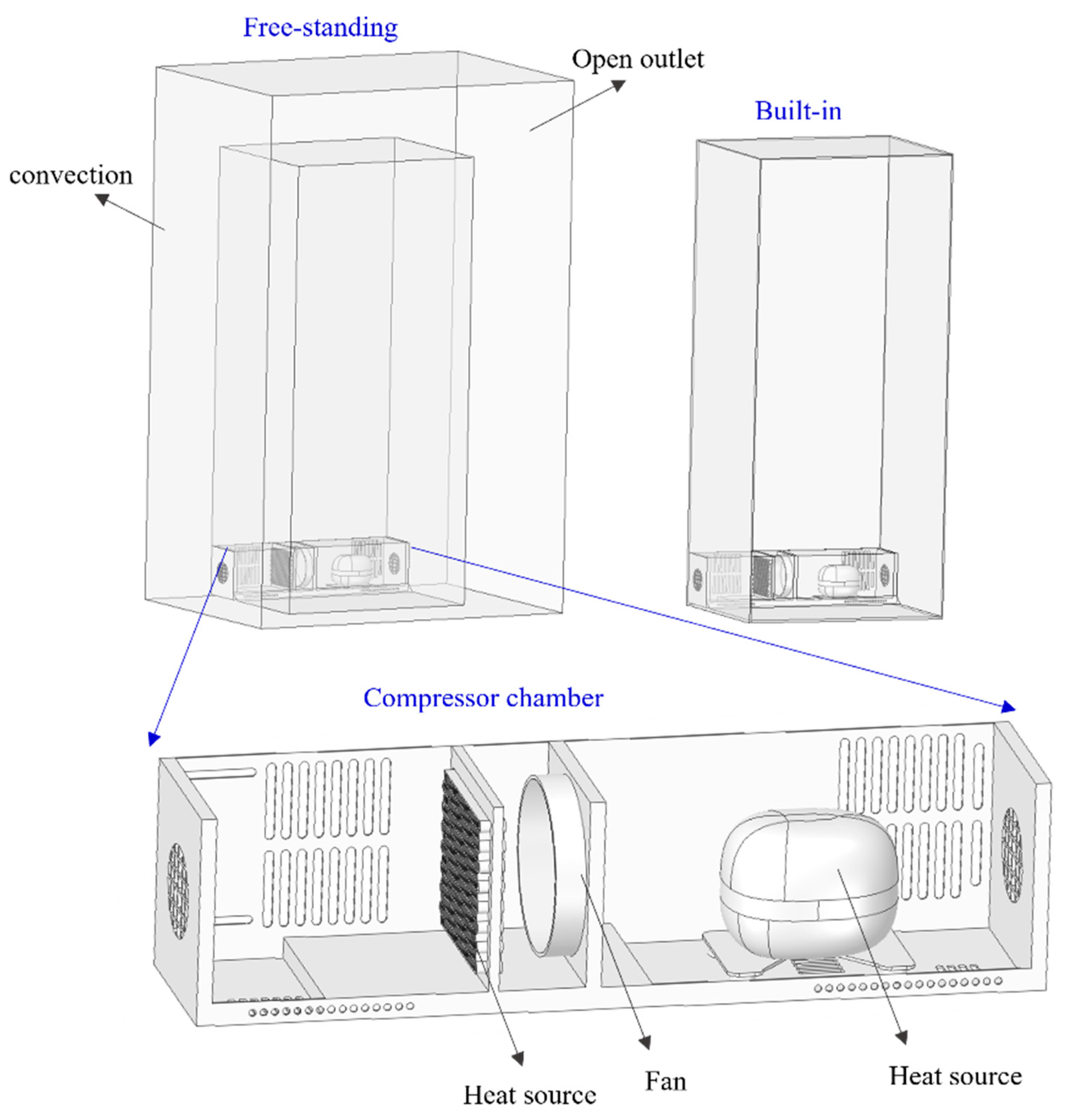
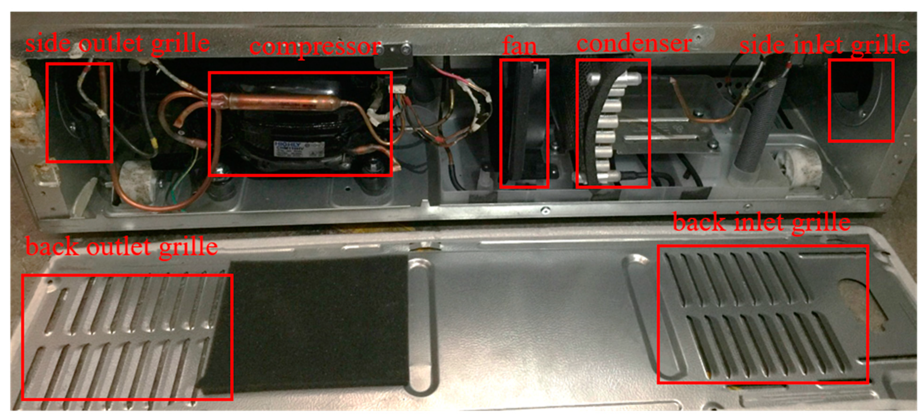
The structure of the compressor chamber is displayed in Figure 1. The micro-channel condenser, the axial fan, and the compressor were installed in a line, and the air inlet and outlet grille were located on the back panel, and left and right sides of the compressor chamber, respectively. This arrangement is widely used in refrigerators and is representative for condenser heat dissipation research. After the external air flows into the air inlet grille, it first exchanges heat with the micro-channel condenser, cools the compressor top under the drive of the fan, and finally flows out of the air outlet grille.
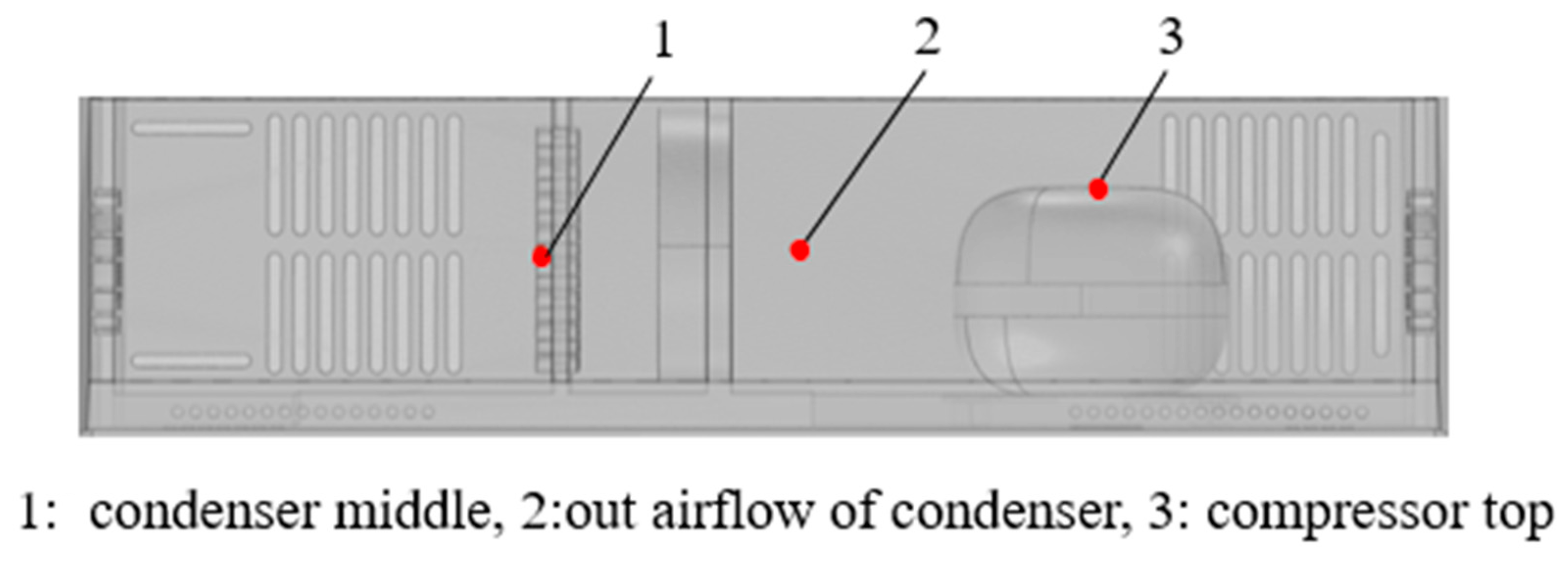
The experimental data were automatically collected and stored by a digital data acquisition system with a personal computer. Calibrated thermocouples (Type T) were installed to measure the temperatures of the compressor chamber, evaporators, and compartments every 15 s. The positions of thermocouples installed in the compressor chamber are described in Figure 2. The thermocouples have a diameter of 0.2 mm and an uncertainty of ±0.2 °C. The humidity data were obtained by an Omega humidity sensor, which has an accuracy of “±3.0%” RH. A Qingzhi 8775A power meter was accessed to monitor the power input of the refrigerator, which has a measurement accuracy of 0.5.

2.2. Test Procedures

Experiments were carried out in a constant-temperature (32.0 ± 0.2 °C) and constant-relative-humidity (50 ± 5%) chamber according to the ISO 15502 Standard [20] and T/CAS 258—2022 Standard. The refrigerator was kept running with empty compartments and the air temperatures inside the RC and FC were controlled at 5.0 ± 2.0 °C and 18 ± 1.5 °C, respectively. The VC was set to the fresh-food mode.
The tested refrigerator was installed under free standing and built-in conditions. In the experiment under the built-in condition, the tested refrigerator was placed on a wooden platform about 200 mm high from the ground. The built-in cabinet was made of wood material that had a thickness of 15 mm. The back of the refrigerator was 5 mm from the wall, the left and right sides and the top of the refrigerator were 5 mm from the wooden cabinet, and the bottom of the refrigerator was 10 mm from the ground. Three consecutive frosting and defrosting cycles were completed in each experiment.

3. Numerical Method

3.1. Description of the Physical Model

Figure 3 illustrates the physical models of the refrigerator with free-standing and built-in configurations. The simulation analysis is focused on the airflow organization and heat transfer between the compressor chamber of the refrigerator and the outside air. The internal chambers of the refrigerator are not involved. Therefore, the air in the compressor chamber and the air between the refrigerator and the wall are selected as objects for numerical simulation. Some small structures, such as screws and rounded corners, are simplified.

3.2. Assumptions and Boundary Conditions

The 3D steady flow models of the refrigerator are built in the computational fluid dynamics software COMSOL 5.3. The following assumptions are made in this study:
  • A steady-state condition is assumed for numerical simulation.
  • The refrigerator is analyzed under no-load and closed-door conditions.
  • The airflow is considered as an incompressible Newtonian fluid.
  • The Boussinesq assumption is applied and viscous dissipation is neglected.
  • The radiative heat transfer between the compressor chamber and the wall is neglected.
  • The flow is assumed to be turbulent and the k–ε turbulence model is used.
  • The airflow is assumed as dry air and the effects of air leakage are neglected.
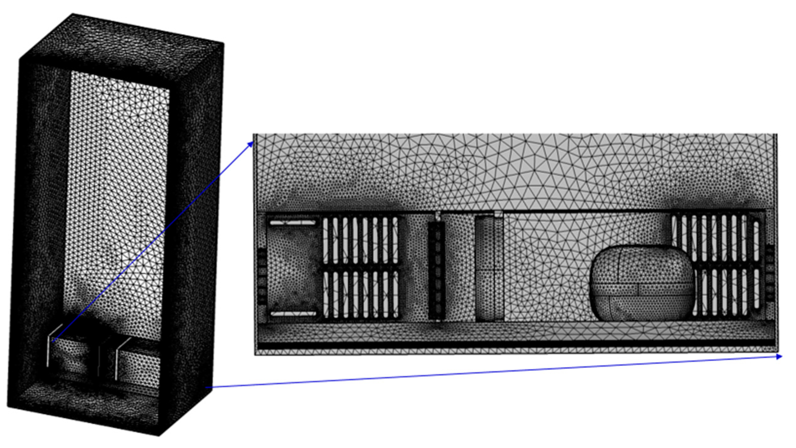
The display of the governing equations is omitted as they are all well known. The unstructured meshes are composed of triangular and tetrahedral elements, as shown in Figure 4. The air volume of the fan is a very important output parameter in the simulation. We choose this output parameter as the detection value. After grid division and calculation several times, it is found that the air volume of the fan hardly changes (less than 1%) when the grid number is more than 4 million. Thus, it can be considered that the grid can meet the requirements of model calculation accuracy. The MUMPS direct solver is used with the GMRES algorithm. The relative tolerance is set as 0.001.
The boundary conditions of the simulation are shown in Figure 3 and Table 2. The pressure and velocity of the fan boundary are obtained from the actual characteristic curve of the axial flow fan, which is simplified to linear form in the simulation. The inlet and outlet of the airflow are set as an open boundary condition with a pressure equal to 0 Pa. The heat release from the condenser and the compressor is estimated based on the formula [21] and the refrigerator operating parameters. The heat transfer coefficients between the airflow and the refrigerator cabinet, and the cupboard and the ground are calculated by their thermal conductivity and convective heat transfer coefficients.

3.3. Model Validation

The comparison of numerical calculation and experimentally measured temperatures of some monitored points in Figure 2 is shown in Table 3. The differences between the simulated value and the experimental value are all within ±3.5 °C. Considering the periodicity of the actual operation of the refrigerator, the measurement error of the thermocouple, and the instability of the airflow and heat transfer, the above error is within the acceptable range. Thus, it can be considered that the numerical simulations show relatively acceptable agreement with the experimental results.

4. Results and Discussion

4.1. The Performance Deterioration of the Fan-Supplied Condenser under Built-In Configuration

4.1.1. Analysis of the Airflow Field around the Condenser-Compressor Room

The simulation results of the airflow rate for two configurations are compared in Table 4. The hot air from the compressor chamber flows across the gap between the refrigerator and wall and releases its heat into the atmosphere. This paper defines this part of the air as the effective airflow. In addition, there is also part of the hot air that has not been discharged outside but directly flows back to the compressor chamber. This part of the air does not take away the heat in the compressor chamber and is defined as the short-circuited hot airflow. The airflow through the fan is called the overall airflow of the system, which is the sum of the effective airflow and short-circuited hot airflow according to the principle of flow conservation.
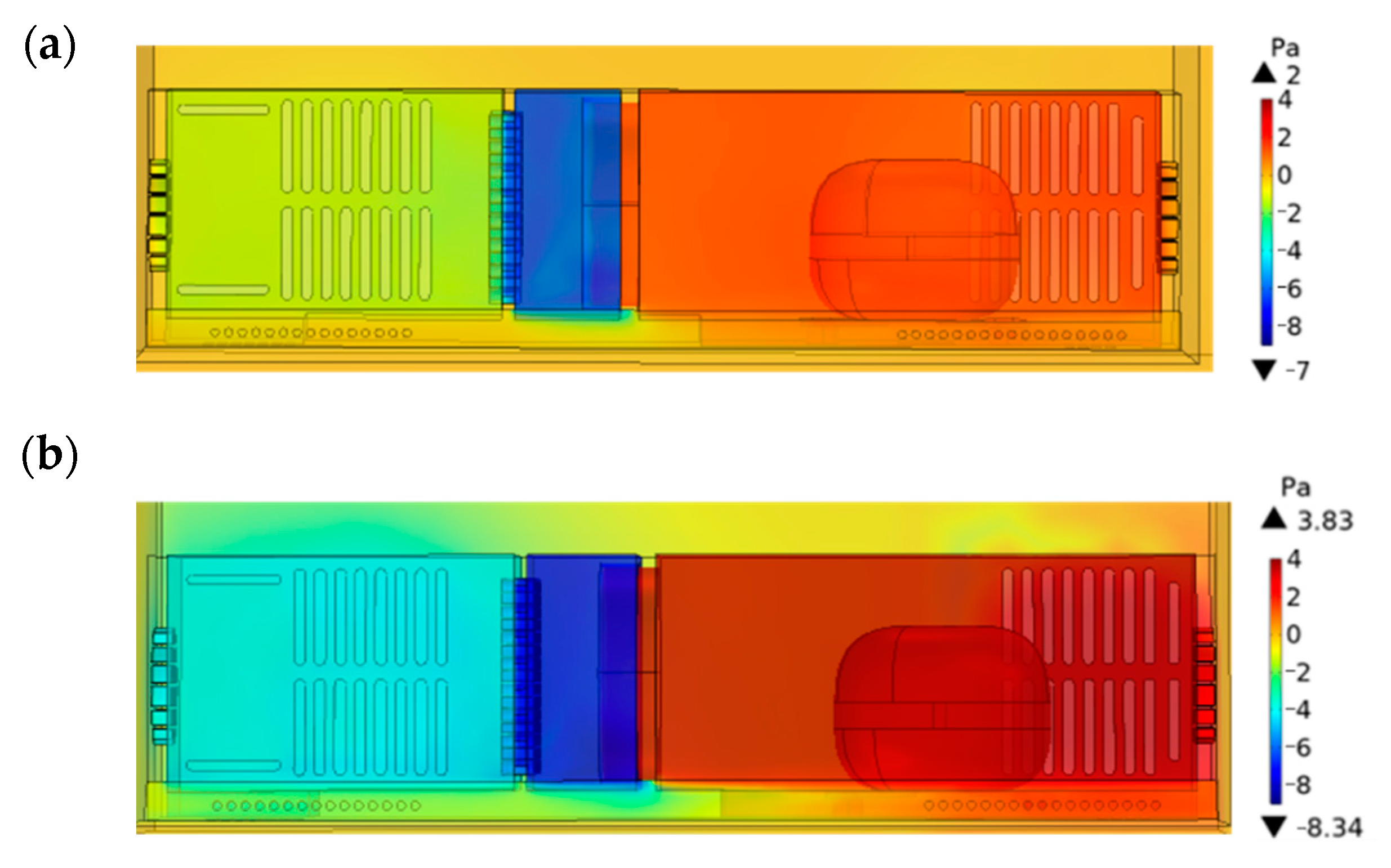
Table 4 illustrates that the effective airflow rate for the built-in configuration is 0.00396 m3·s−1, 66.1% lower than that for the free-standing configuration. One reason for that is the overall airflow rate reduction. The built-in condition makes the airflow channel between the compressor chamber and the outside air become long and narrow, which increases the flow resistance of air-forced convection driven by the fan. As shown in Figure 5, the pressure drop of the fan increases from 9 Pa to 12.17 Pa. Therefore, the overall airflow rate through the fan decreases according to the fan performance curve.
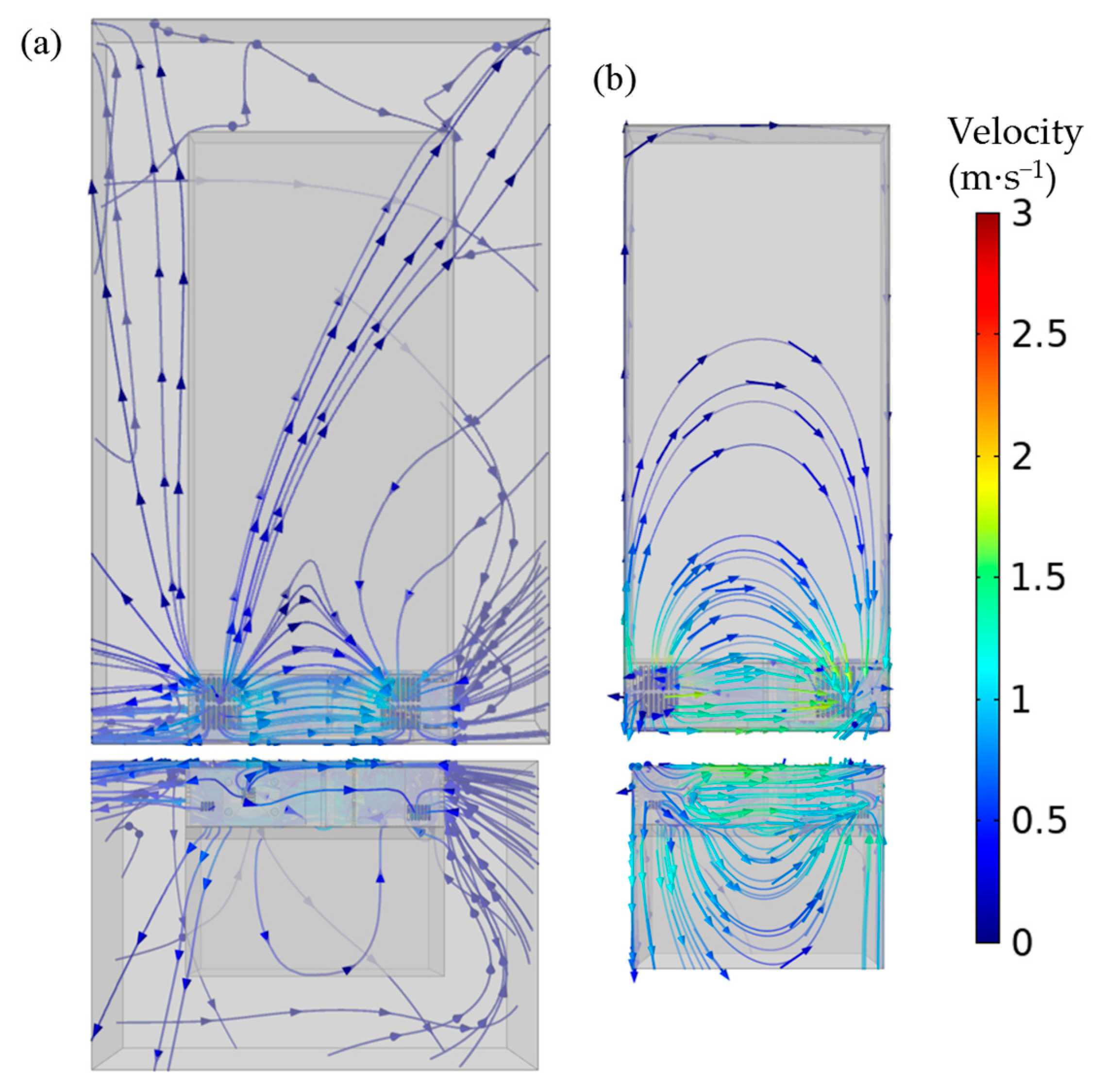
The second reason for the effective airflow rate reduction is the increase in short-circuit hot air rate. The short-circuit hot air rate for the built-in configuration is 0.00969 m3·s−1, 30.7% higher than that for the free-standing configuration. The short-circuit hot air ratio also increases by 32.2%. The airflow is driven by the axial flow fan; enters the compressor bin from the back, side, and bottom air grille; flows through the condenser, fan, and compressor in turn; then flows out of the back and side bottom air grille. However, there are differences in the main flow paths between the two installation conditions, as shown in Figure 6.
Under the free-standing condition, all the surrounding areas of the refrigerator are open space except for the back distance of 20 mm from the wall. The airflow resistance is lowest through the side grille of the compressor chamber. By contrast, under the built-in condition, the airflow resistance is lowest through the bottom grille as the bottom of the refrigerator is 10 mm from the ground.
Two main short-circuit paths of the built-in refrigerator are located based on the velocity vectors and streamlines. One is from the compressor back outlet grille, along the gap between the refrigerator and the back wall, into the condenser back inlet grille. The other is from the compressor bottom outlet grille, along the gap between the refrigerator and the ground, into the condenser bottom outlet grille. The air inlet grille is under negative pressure and the air outlet grille is under positive pressure, while the external environment is under atmospheric pressure. Therefore, part of the air flowing out of the compressor chamber will flow to the inlet grille with greater pressure difference, shorter distance, and less resistance, rather than the external environment. Therefore, the airflow short circuit phenomenon happens.
Based on the analysis above, it can be concluded that the built-in condenser has poor performance attributed to two reasons: 28.6% lower condenser air flowrate and 10.72 °C higher condenser inlet air temperature caused by the hot short-circuited airflow. Therefore, two corresponding solution ideas for the future optimization of built-in refrigerators can be proposed. We can increase the condenser overall airflow rate by increasing the airflow area or reduce the short-circuited airflow rate by placing a barrier in the short-circuited paths located above. Figure 7 illustrates a mind map of solution ideas and specific approaches to heat dissipation deterioration problems for built-in refrigerators.

4.1.2. Heat Dissipation Performance of the Condenser-Compressor Room

The temperature contours of the compressor chamber for two configurations are displayed in Figure 8. Compared with the free-standing configuration, the temperature in the compressor room increases obviously under the built-in configuration. Some temperature values in key positions are displayed in Table 5.
Table 5 presents that the temperature in the middle of the condenser increases by 11.31 °C, which can represent the condensing temperature. One reason for that is the lower overall airflow rate for convection, as stated in Section 4.1.1. The other reason is the high inlet temperature due to the airflow short-circuit phenomenon, 10.72 °C higher than that in the free-standing condition, as shown in Table 5. Therefore, the heat transfer temperature difference between the condenser and air will increase to maintain the heat dissipation of the condenser.
The discharge temperature of the compressor under the built-in condition is 63.09 °C, 12.53 °C higher than that under the free-standing condition. The temperature and pressure of the condenser increase under the built-in condition, as mentioned above, but the evaporating temperature is limited by the chamber temperature setup. The refrigerant pressure in the evaporator hardly changes. Therefore, as the pressure ratio of the compressor increases, the rotating speed and power of the compressor also increase. The discharge temperature and heat production of the compressor will increase consequently. The flow characteristic of forced-convention air is studied by a numerical method. This numerical study reveals the internal mechanism of condenser performance deterioration and provides an explanation of the refrigerator experiment phenomenon in the following section.

4.2. The Performance Deterioration of Refrigerator under Built-In Configuration

Under the free-standing condition, the operating time of the tested refrigerator is 72 h between two defrost actions, including 45 periodical on/off cycles and 3 defrosting recovery cycles. For the built-in installation condition, the operating time is about 30 h, including 31 periodical on/off cycles and 1 defrosting recovery cycle. Then, the time-average values of the power input, the compressor-on time ratio, and energy consumption are calculated based on the on/off cycles, as shown in Table 6.
For the refrigerator with the inverter compressor, the pressure ratio and rotating speed of the compressor will increase due to the poor heat dissipation performance of the condenser. Table 6 illustrates that the compressor ON-time ratio slightly reduces by 8% but the power during the compressor-on period greatly increases by 56.9%. In general, the energy consumption of a refrigerator can be calculated by Equation (1) and can be approximately equivalent to a product of the compressor-on time ratio and the average power input during the compressor-on period. Therefore, the refrigerator average power and energy consumption under the built-in installation condition reach 75.66 W and 1.82 kW·h, respectively, which increase significantly by 43.4% compared with the results under the free-standing condition.
W = P ¯ × 24   h = ( η × P o n + ( 1 η ) × P o f f ) × 24   h η × P o n × 24   h
In order to study the dynamic characteristics of the built-in refrigerator, the real-time data of a typical on/off cycle are selected. The temperature variations of two evaporators and three compartments are analyzed as follows.
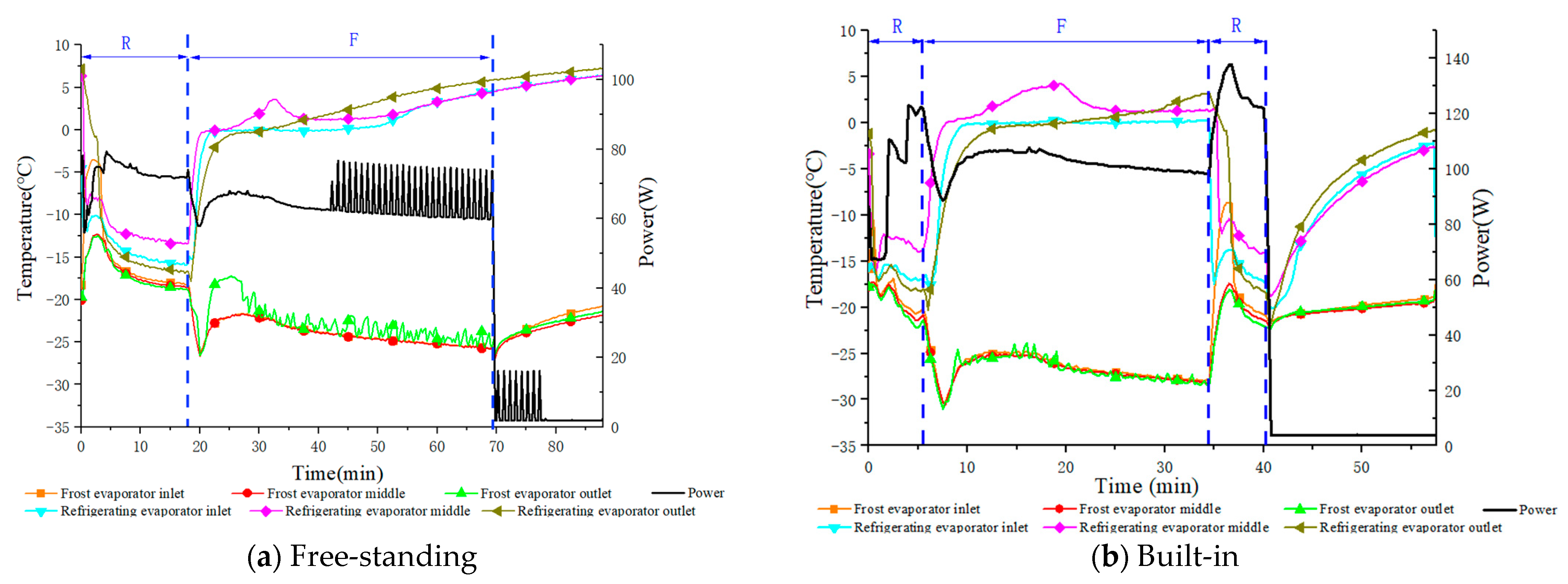
The evaporating temperatures for the two installation conditions are displayed in Figure 9. The initial time of the selected on/off cycle is regarded as 0 min. The initial time of the on/off cycle is defined when the input power changes most sharply in response to the switch between the on and off cycle. Table 7 lists the surface temperature of the evaporator at the terminal time of the refrigerating mode (R-mode for short) and the terminal time of the freezing mode (F-mode for short).
Figure 9 and Table 7 show that the evaporating temperature reduces after the refrigerator is built-in. At the termination of the R-mode, the inlet and outlet temperatures of the refrigerating evaporator (RE for short) reduce by 0.78 °C and 1.98 °C, respectively. At the termination of the F-mode, the inlet and outlet temperatures of the freezing evaporator (FE for short) reduce by 2.29 and 2.81 °C, respectively. The rotating speed of the compressor increases due to the poor heat dissipation performance of the condenser. The lower evaporating temperature can be attributed to the higher compressor rotating speed but is limited by the chamber temperature setup.
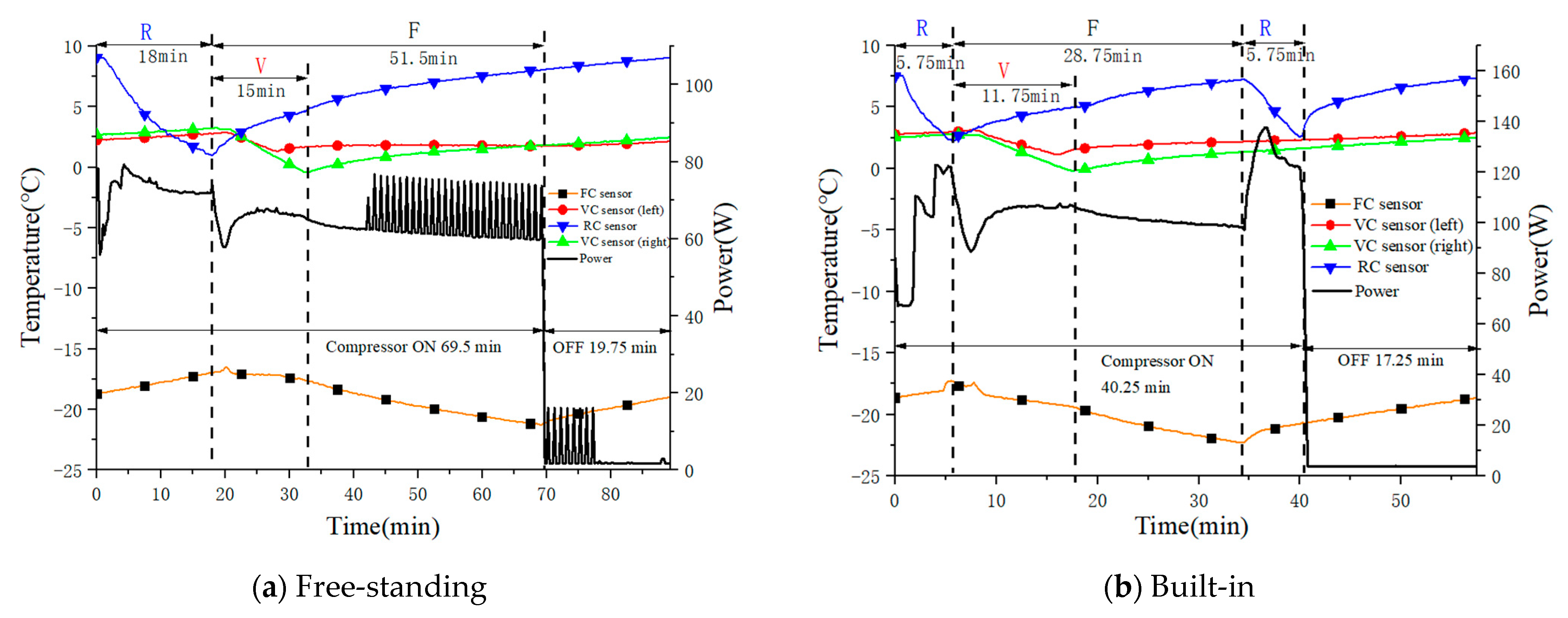
Under different installation conditions, the operation mode of the refrigerator also changes accordingly. Figure 10 illustrates the power and temperature variations of compartments during the on/off cycle. Under the free-standing condition, the refrigerator follows the operation mode of “refrigerating—variable temperature and freezing—freezing”. By contrast, the built-in refrigerator follows the operation mode of “refrigerating—variable temperature and freezing—freezing—refrigerating”. That means that the R-mode runs twice in a single on/off cycle. As shown in Figure 10b, the temperature of the RC sensor drops to 2.24 °C at 5.75 min and the three-way valve switches to the freezing evaporator. At this time, the air in the RC is not evenly cooled, due to the rapid cooling rate. After 34.5 min, the temperature around the sensor rises to the set value, so the R-mode runs for the second time.
The running time of each period is displayed in Table 8. The results show that the running time of the built-in refrigerator in each period is shorter than that of the free-standing one. The ON-time ratio of compressor η also decreases from 78.2% to 70.2%. This is because, as mentioned above, a lower evaporating temperature brings about the increase in the cooling rate of compartments. However, the power during the compressor-on period greatly increases to make it at the same time.
In general, the condensing temperature and discharge temperature will increase due to poor heat dissipation performance of the condenser under the built-in configuration. The rotating speed and power of the compressor will increase accordingly to compensate for the capacity loss. Therefore, the evaporating temperature will be lower and the on/off cycle mode of the refrigerator may change due to the rapid cooling rate. The compressor ON-time ratio will slightly reduce by 8% but the power during the compressor-on period will greatly increase by 56.9%. Consequently, the combined effect leads to an overall increase of 43.4% in the energy consumption.

5. Conclusions and Prospects

A refrigerator simulation model is established and experimentally verified to study the performance deterioration of the condenser caused by the built-in condition. The overall performance of the built-in and free-standing refrigerators is comparatively studied though experiments. The main conclusions are as follows:
  • The built-in condenser has poor performance attributed to two reasons: one is that the built-in condenser has a lower total air flowrate than the free-standing one. Furthermore, most of the air (70.1%) flowing out of the compressor room will flow to the inlet grille with a greater pressure difference, shorter distance, and less resistance, rather than the external environment. This part of the airflow is short-circuited, increasing the condenser inlet air temperature.
  • The heat dissipation deterioration increases the condensing temperature by 11.31 °C and discharge temperature by 12.53 °C, resulting in the refrigerator cooling capacity loss. Both the rotating speed and power of the compressor increase to cover the capacity loss, pulling the evaporating temperature lower. The on/off cycle mode of the refrigerator may also change due to the rapid cooling rate.
  • The compressor ON-time ratio will slightly reduce by 8% but the power during the compressor-on period will greatly increase by 56.9%. Consequently, the combined effect leads to an overall increase of 43.4% in the energy consumption of the built-in refrigerator.
  • Based on the analysis above, there are some potential solutions to built-in refrigerators’ heat dissipation problem. We can increase the overall airflow rate by increasing the airflow area (such as increasing the bottom height and grille area) or reduce the short-circuited airflow rate by placing a barrier in the short-circuited paths located in Section 4.1.1. This study can provide guidance for the airflow field and heat dissipation optimization of built-in refrigerators.

Author Contributions

Conceptualization, D.H.; data curation, Y.S.; formal analysis, R.Z.; funding acquisition, D.H.; investigation, Y.S. and Y.Y.; methodology, Y.S.; software, Y.S.; validation, Y.Y.; writing—original draft, Y.S.; writing—review and editing, Y.S., R.Z. and D.H. All authors have read and agreed to the published version of the manuscript.

Funding

This research was funded by the National Natural Science Foundation of China, grant number 51876154, and Major Science and technology innovation engineering projects of Shandong Province, grant number 2019JZZY020813.

Data Availability Statement

Not applicable.

Conflicts of Interest

The authors declare no conflict of interest.

Nomenclature

Greek
ηcompressor ON-time ratio (-)
Roman
Ttemperature (K)
hheat transfer coefficient (W· m−2·K−1)
P input power (W)
Qquantity of heat (W)
W energy consumption (kW·h)
uair velocity (m·s−1)
pPressure (Pa)
subscripts
maxmaximum
onduring compressor ON
offduring compressor OFF
Abbreviations
PCM phase change material
RCrefrigerating compartment
VCvariable compartment
FCfreezing compartment
R-moderefrigerating mode
F-modefreezing mode
RErefrigerating evaporator
FEfreezing evaporator

References

  1. Ghadiri, F.; Rasti, M. The effect of selecting proper refrigeration cycle components on optimizing energy consumption of the household refrigerators. Appl. Therm. Eng. 2014, 67, 335–340. [Google Scholar] [CrossRef]
  2. Kruzel, M.; Bohdal, T.; Dutkowski, K.; Kuczyński, W.; Chliszcz, K. Current Research Trends in the Process of Condensation of Cooling Zeotropic Mixtures in Compact Condensers. Energies 2022, 15, 2241. [Google Scholar] [CrossRef]
  3. Zhang, Z.; Huang, D.; Zhao, R.; Leng, Y. Effect of airflow field optimization around spiral wire-on-tube condenser on a frost-free refrigerator performance. Appl. Therm. Eng. 2017, 114, 785–792. [Google Scholar] [CrossRef]
  4. Bassiouny, R. Evaluating the effect of the space surrounding the condenser of a household refrigerator. Int. J. Refrig. 2009, 32, 1645–1656. [Google Scholar] [CrossRef]
  5. Agilis, D.V. Influence of surrounding space on heat transfer effectiveness of refrigerator’s condenser. Mechanika 2012, 18, 323–329. [Google Scholar]
  6. Afonso, C.; Matos, J. The effect of radiation shields around the air condenser and compressor of a refrigerator on the temperature distribution inside it. Int. J. Refrig. 2006, 29, 1144–1151. [Google Scholar] [CrossRef] [Green Version]
  7. Devle, M.; Garg, A.; Cavali, D. Thermal management of machine compartment in a built-in refrigerator. MATEC Web Conf. 2018, 240, 05005. [Google Scholar] [CrossRef]
  8. Belman-Flores, J.M.; Heredia-Aricapa, Y.; García-Pabón, J.J.; Gallegos-Muñoz, A.; Serrano-Arellano, J.; Pérez-Reguera, C.G. An approximate model of a multilayer wire-on-tube condenser operating with R134a and R600a: Experimental validation and parametric analysis. Case Stud. Therm. Eng. 2021, 25, 100927. [Google Scholar] [CrossRef]
  9. Gönül, A.; Ağra, Ö.; Atayılmaz, Ş.Ö.; Demir, H.; Sevindir, M.K.; Teke, İ. Experimental and numerical investigation of air-side forced convection on wire-on-tube condensers. Int. J. Sci. 2020, 151, 106241. [Google Scholar] [CrossRef]
  10. Ameen, A.; Mollik, S.A.; Mahmud, K.; Quadir, G.A.; Seetharamu, K.N. Numerical analysis and experimental investigation into the performance of a wire-on-tube condenser of a retrofitted refrigerator. Int. J. Refrig. 2006, 29, 495–504. [Google Scholar] [CrossRef]
  11. Hrnjak, P.; Litch, A.D. Microchannel heat exchangers for charge minimization in air-cooled ammonia condensers and chillers. Int. J. Refrig. 2008, 31, 658–668. [Google Scholar] [CrossRef]
  12. Doğan, B.; Ozturk, M.M.; Tosun, T.; Tosun, M.; Erbay, L.B. A novel condenser with offset strip fins on a mini channel flat tube for reducing the energy consumption of a household refrigerator. J. Build. Eng. 2021, 44, 102932. [Google Scholar] [CrossRef]
  13. Oh, S.H.; Lee, S.H.; Lee, D.; Moon, S.H.; Kim, Y. Air-side heat transfer and pressure drop characteristics of flat-type, U-and V-shaped microchannel condensers for refrigerator applications. Int. J. Heat Mass Transf. 2021, 176, 121460. [Google Scholar] [CrossRef]
  14. Ling, L.; Zhang, Q.; Yu, Y.; Wu, Y.; Liao, S. Study on thermal performance of micro-channel separate heat pipe for telecommunication stations: Experiment and simulation. Int. J. Refrig. 2015, 59, 198–209. [Google Scholar] [CrossRef]
  15. Knipper, P.; Bertsche, D.; Gneiting, R.; Wetzel, T. Experimental investigation of heat transfer and pressure drop during condensation of R134a in multiport flat tubes. Int. J. Refrig. 2019, 98, 211–221. [Google Scholar] [CrossRef]
  16. Cheng, W.-L.; Mei, B.-J.; Liu, Y.-N.; Huang, Y.-H.; Yuan, X.-D. A novel household refrigerator with shape-stabilized PCM (Phase Change Material) heat storage condensers: An experimental investigation. Energy 2011, 36, 5797–5804. [Google Scholar] [CrossRef]
  17. Cheng, W.-L.; Ding, M.; Yuan, X.-D.; Han, B.-C. Analysis of energy saving performance for household refrigerator with thermal storage of condenser and evaporator. Energy Convers. Manag. 2017, 132, 180–188. [Google Scholar] [CrossRef]
  18. Yuan, X.-D.; Cheng, W.-L. Multi-objective optimization of household refrigerator with novel heat-storage condensers by Genetic algorithm. Energy Convers. Manag. 2014, 84, 550–561. [Google Scholar] [CrossRef]
  19. Maiorino, A.; Del Duca, M.G.; Mota-Babiloni, A.; Greco, A.; Aprea, C. The thermal performances of a refrigerator incorporating a phase change material. Int. J. Refrig. 2019, 100, 255–264. [Google Scholar] [CrossRef]
  20. ISO 15502; Household refrigerating appliances-Characteristics and test methods. American National Standards Institute: New York, NY, USA, 2005.
  21. Sun, Y.; Sun, Y. Analysis of the Chassis Cooling of Refrigeration Compressors. Refrig. Air Cond. Electr. Power Mach. 2010, 31, 61–63. [Google Scholar] [CrossRef]
Figure 1. Structure diagram of the compressor chamber.
Energies 15 08666 g001
Figure 2. The positions of T-type thermocouples installed in the compressor chamber.
Energies 15 08666 g002
Figure 3. CFD model of the refrigerator under two installation conditions.
Energies 15 08666 g003
Figure 4. Mesh distribution of numerical model.
Energies 15 08666 g004
Figure 5. Pressure contours of the compressor chamber for two configurations: (a) free-standing and (b) built-in.
Energies 15 08666 g005
Figure 6. Velocity vectors and streamlines of the refrigerator for two configurations (m·s−1): (a) free-standing and (b) built-in.
Energies 15 08666 g006
Figure 7. Flow chart of solution ideas and specific approaches to heat dissipation deterioration in built-in refrigerators.
Energies 15 08666 g007
Figure 8. Temperature contours of condenser-compressor room for two configurations (°C): (a) free-standing and (b) built-in.
Energies 15 08666 g008
Figure 9. Comparison of the power and evaporating temperature during on/off cycle.
Energies 15 08666 g009
Figure 10. Comparison of the power and temperature of FC, VC, and RC during on/off cycle.
Energies 15 08666 g010
Table 1. The main technical parameters of the tested frost-free refrigerator.
ItemsParametersItemsParameters
Star grade***Efficiency grade1
RefrigerantR600aClimate typeSN, N, ST, T
Refrigerant charge (g)65CondenserMicro-channel
Dimensions (mm)905 × 617 × 1900Weight (kg)165
FC volume (L)178Throttle deviceCapillary Tube
VC volume (L)25 + 24Rated voltage (V)220
RC volume (L)273Rated frequency (Hz)50
The star grade ‘***’ indicates that the freezer temperature of this refrigerator should be no higher than −18 °C.
Table 2. Boundary conditions of numerical models.
ItemSetup
Fanpmax = 25.5 Pa, umax = 0.025 m·s−1
Inlet and outletp = 0 Pa
Inlet airflowT = 32 °C
CondenserQ = 100 W
CompressorQ = 20 W
The refrigerator cabineth = 0.4 W·m−2·K−1, T = −20 °C
The cupboard and the groundh = 0.2 W·m−2·K−1, T = 32 °C
Other wallsThermal insulation
Table 3. The comparison of experimental and simulated temperatures.
PositionsFree-Standing/°CBuilt-In/°C
Exp. TSim. TDifferenceExp. TSim. TDifference
Condenser middle38.939.4+0.550.753.0+2.3
Out airflow of condenser38.438.9+0.549.351.5+2.2
Compressor top53.251.0−2.269.673.0+3.4
Table 4. Simulation results of the airflow rate for two configurations.
Free-StandingBuilt-InDifference
Overall airflow rate (m3·s−1)0.01910 (0.02175 kg/s)0.01365 (0.01502 kg/s)−28.6% (−30.6%)
Effective airflow rate (m3·s−1)0.011690.00396−66.1%
Short-circuit hot air rate (m3·s−1)0.007410.00969+30.7%
Short-circuit hot air ratio38.8%71.0%+32.2%
Table 5. The temperature of positions in condenser-compressor room for two configurations.
Free-Standing/°CBuilt-In/°CDifference/°C
Airflow inlet temperature32.8243.54+10.72
Condensing temperature 39.1550.46+11.31
Discharge temperature50.5663.09+12.53
Table 6. Overall refrigerator performance for two configurations.
Free-StandingBuilt-InDifference
Compressor ON-time ratio η 78.2%70.2%−8.0%
Power during compressor ON P o n 66.69 W104.65 W+56.9%
Power during compressor OFF P o f f 3.29 W3.90 W+18.5%
Average power P ¯ 52.77 W75.66 W+43.4%
Energy consumption W1.27 kW·h1.82 kW·h+43.4%
Table 7. Comparison of evaporating temperature on the termination of R and F mode.
Free-Standing/°CBuilt-In/°CDifference/°C
The terminal time of R-modeRE inlet−15.71−16.49−0.78
RE middle−13.42−13.74−0.32
RE outlet−16.65−18.63−1.98
The terminal time of F-modeFE inlet−25.73−28.02−2.29
FE middle−25.81−28.09−2.28
FE outlet−25.53−28.34−2.81
Table 8. Comparison of running time in each period during on/off cycle.
R-ModeV-F-ModeF-ModeONOFFη
Free-standing/min181536.569.519.7578.2%
Built-in/min5.75 + 5.7511.751740.2517.2570.2%
Difference−36.1%−21.7%−53.4%−42%−12.7%−8.0%
Publisher’s Note: MDPI stays neutral with regard to jurisdictional claims in published maps and institutional affiliations.