Review

Heat Transport in Rotating Annular Duct: A Short Review

1
MAST-GPEM, University Gustave Eiffel, F-44344 Bouguenais, France
2
IMT Atlantique Département Systèmes Énergétiques et Environnement, UMR CNRS GEPEA, F-44007 Nantes, France
*
Author to whom correspondence should be addressed.
Energies 2022, 15(22), 8633; https://doi.org/10.3390/en15228633
Submission received: 30 September 2022 / Revised: 28 October 2022 / Accepted: 13 November 2022 / Published: 17 November 2022

Abstract

:
Heat transport in rotating processes finds a wide range of application in which academic issues in the fluid mechanics and heat transfer areas are here reported. This paper discusses successive works from the seminal paper of Taylor (1923) to recent numerical results established from a broad range of methods such as DNS, LES, RANS or LB methods. The flow regimes identification is thus reported in Taylor–Couette geometry. The role of the axial flow rates in the apparition, stabilization and destruction of the large-scale of the turbulent structures is depicted in the case of Taylor–Couette–Poiseuille geometry. In a non-isothermal condition, a discussion is held on the various exponent values found in the scaling relationships relying on the Nusselt number as a function of the Rayleigh or Reynolds numbers according to the regimes of thermal convection.

1. Introduction

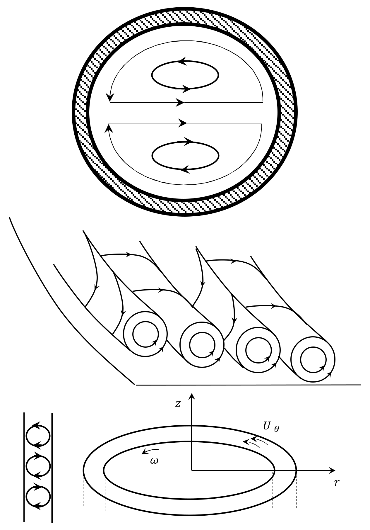
Heat transport throughout rotating annular geometries covers a large spectrum of applications from natural to engineering domains. In the energy systems, it has shown great potential for the rotating wall cooling systems of electrical engines [1], turbine generators [2], rotary kilns [3], supercritical CO2 extraction [4], and nuclear fusion reactors [5], to cite a few examples. The physical problems are shown in Figure 1 in the cylindrical coordinate system ( r , θ , z ) .
The inclination of the system with the gravity is aimed to work under vertical, horizontal or inclined orientations. The fluid motion is performed in the annular gap. The heat flux density can be exerted from the external or the inner surface in order to impose a radial temperature difference. Under an isothermal condition, the influence of the curved wall upon the Dean vortices apparition is a first class of instabilities known in annular geometry. The rotational effect of the inner or external wall has resulted in a second class of instabilities. Such flows type are known under the name of Rotor–Stator cavities [6], Taylor–Couette [7] or Taylor–Couette–Poiseuille [8] if an axial flow rate is superimposed to the rotation. They have the particularity of reaching a high level of complexity from the point of view of the turbulence properties. Indeed, the turbulence is auto-sustained by the rotation effect that differs from a traditional wall-bounded flow, for which it is necessary to impose an external forcing to suppress the turbulence decay [9]. The centrifugal and axial motions are driven from a set of dimensionless numbers; the axial Reynolds number, Rea, Taylor, Ta, or rotational Reynolds numbers, Rew, themselves function of the torque number and geometric parameters [10]. As the Taylor number is increased, organized vortices appear and different flow regimes have been reported. The characterization of these secondary flows from their apparition and destabilization until their destruction at elevated Ta is still a topic of interest. The density-stratification induced by the momentum transport in such geometry is of practical interest for sediment transport in the ocean [11]. Such applications have also been explored for yield-stress fluid, where the flow regimes are different from the Newtonian case. The yield stress tends to stabilize the flow [12]. More recent work [13] supports such a conclusion, showing that two regions coexist, a shear-banding zone (flowing zone) and a dead zone (static zone) at an elevated shear rate.
Under a non-isothermal working condition, the axial flow rate is aimed to release the recovered heat waste, leading to various regimes of thermal convection [14]. The addition of grooves to the inner or outer wall raises the heat transfer magnitude [15]. The thermal stratification, in the sense of the mixed and natural convection, plays a major role in the performance of the annular heat exchanger. According to the geometrical characteristics of the annular passage [16] or the magnitude [17] and direction of the temperature gradient [18], the buoyancy forces will affect the flow regimes identified in the isothermal case. Numerous studies have also been conducted on nanofluids at low volume fraction concentration, Φ v [19]. The thermal instabilities have an impact on the heat transfer for such Newtonian fluids [20]. For non-Newtonian fluid suspension, the rheological behavior of yield-stress fluid is recognized to be sensitive to the heat flux only at a weak imposed shear rate inferior to 0.02 s−1 [21], and that is why few experimental works have been explored in non-isothermal conditions except in forced convection [22]. Therefore, most of the following works were performed in more simple geometry to characterize convective heat transfer coefficients in circular ducts in a large range of axial flow rates [23,24].
Table 1 recaps the range of values reported in various applications of the literature.
While important reviews have been conducted on simple annular geometry without a rotating effect for a double-pipe heat exchanger application [19,33], there are, according to our knowledge, no reviews that focus on the heat transport in rotating annular ducts. The benefits of this review are to reach triple objectives covering the theory development, the applications and the modelling aspects.

2. Iso-Thermal Condition

In an isothermal case, the study of the vortex motion is a subject that has been widely studied for the last century in the scientific community. The interest of vortex flows lies in the possibility to significantly increase heat transfer while minimizing energy costs. Depending on the geometry adopted, the vortices produced may or may not be maintained throughout the flow. As an example, we briefly present the centrifugal instabilities that occur when using concave and/or convex walls (Figure 2):
-
The Taylor-Couette instability is a vortex confined between two coaxial cylinders with the outer cylinder stationary and the inner cylinder rotating at a constant angular velocity.
-
The Dean instability is a flow induced by the curvature of the streamlines of a fully developed Newtonian flow. Above a critical value of the Dean number, a pair of vortex cells appears within the flow near the outer wall of the pipe.
-
The Görtler instability is a secondary flow appearing in the boundary layer of the flow along a concave wall. This flow appears as longitudinal rolls, counter-rotating in pairs, aligned in the direction of the mean flow. Its appearance is caused by a competition between pressure and centrifugal forces.

2.1. Taylor-Couette Flow
Taylor–Couette flow occurs between two concentric cylinders of radius R i for the inner cylinder and R e   for the outer cylinder in rotation (Figure 2). This flow has been extensively studied in the literature since Taylor’s early work in 1923 [34], and remains a major topic of study in the fluid mechanics area.
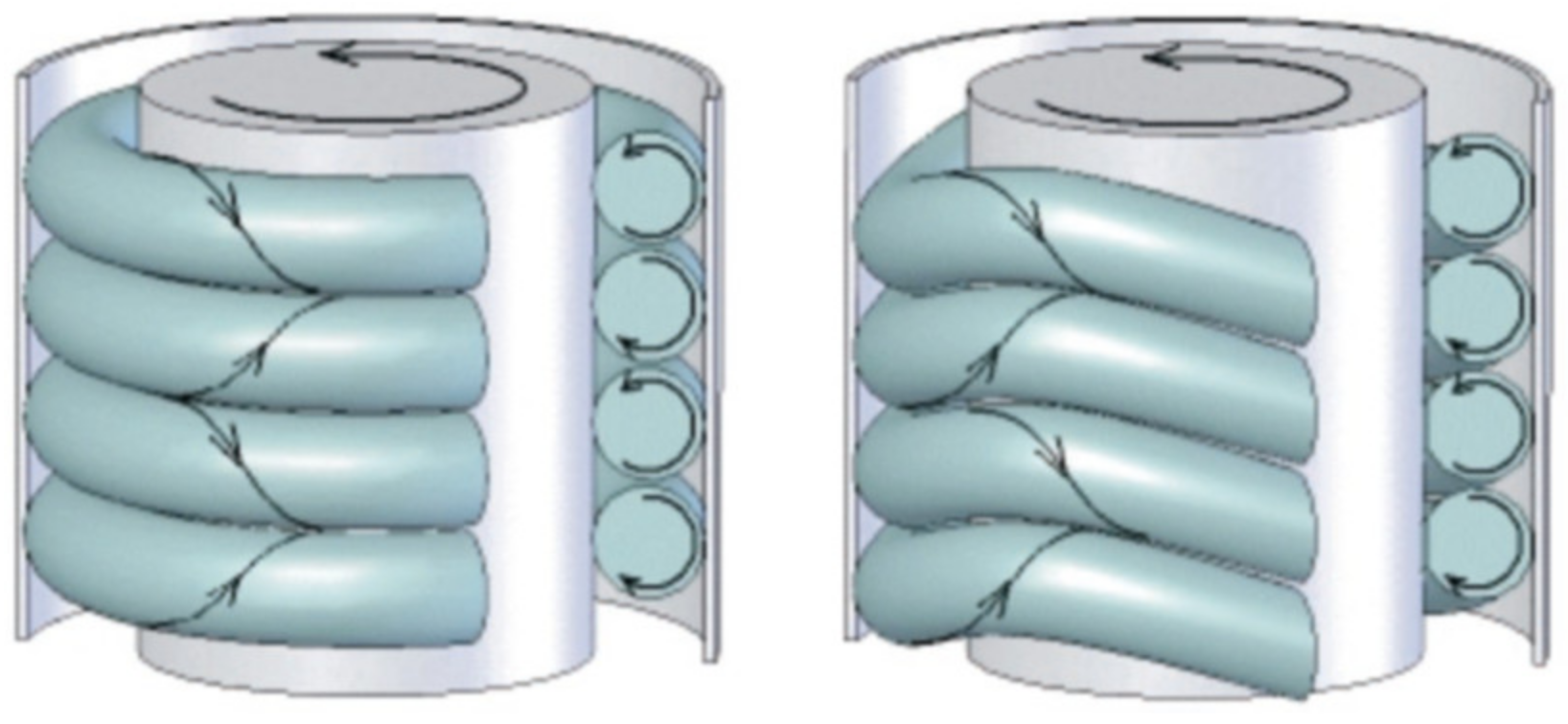
The Taylor–Couette flow has a succession of very rich bifurcations generating more and more complex flows, finally leading to the turbulence. The different instabilities appear in the flow with the increase of the rotation velocity of the cylinder. When the angular velocity of the cylinder exceeds a critical value ω c , a first instability appears, forming a pair of counter-rotating toroidal vortices regularly spaced along the axis surrounding the cylinder like a vortex ring. These vortices are often referred to in the literature as the “Taylor roll” or “Taylor-Görtler instability” (Figure 3). This instability is generic, i.e., likely to occur in any flow deflected by a wall creating a pressure gradient normal to the streamlines.
Then, when a small axial flow is added to the Taylor–Couette flow, advection of the vortices occurs from the axial flow without being destroyed. Taylor (1923) [34] was the first to observe the instability of a fluid confined between two coaxial cylinders with a rotating inner cylinder. Subsequently, a series of theoretical, experimental and numerical works followed the seminal work of Taylor (1923) [34], Coles (1965) [35]; Fenstemacher (1979) [36]; and Andereck et al. (1986) [37]. Since the work of Taylor (1923) [34], many studies have been performed on the flow regimes identification in Taylor–Couette geometry. This is very complex and depends on operational and geometric parameters.
The Couette flow is laminar and stationary. It is driven by the viscous forces acting on the fluid and the annular streamlines centered on the rotation axis of the cylinder. Before the first instability, for low rotational speeds, Couette flow is simply characterized by the angular velocity U θ ( r ) . Solving the Navier–Stokes equations under suitable boundaries conditions leads to the following analytical solution:
U θ ( r ) = ω 1 R e 2 R i 2 [ R i 2 R e 2 r r R i 2 ]
Thus, in this study configuration, with only the inner cylinder in rotation, we systematically have the appearance of instabilities due to the increase of the rotation speed. The first instability is characterized by the appearance of stationary cells of toroidal shape, counter-rotating, associated in pairs and regularly ordered in the axial direction. Taylor determined the critical value of the inner cylinder velocity ω c where the first instability is observed for a critical shape factor η 1 . This rotational velocity ω c leads to a critical value of the Taylor number T a c = 1708 . Since Taylor’s early work, several empirical or analytical correlations have been presented to evaluate this threshold. The most widely used correlation was defined by Esser and Grossmann (1996) [38]:
R e ω c = 1 α 2 ( 1 + η ) 2 2 η ( 1 η ) ( 3 + η )   avec   α = 0.1556
Figure 3. Taylor cells (Left-hand) and Wavy Taylor cell (Right-hand) [39].
Energies 15 08633 g003
In the case where the rotational speed increases and the Taylor number exceeds the second threshold, T a c , 2 , the presence of a new instability was demonstrated by Coles (1965) [35]. He observed the presence of ripples at the dividing lines of the Taylor cells. The Taylor cells are no longer perpendicular to the axis of the cylinder, but rather show a wavy behavior. The axisymmetric flow becomes unstable and unsteady and therefore doubly periodic, characterized by an axial and azimuthal wavenumber. When the Taylor number exceeds a third threshold, T a c , 3 , the flow becomes more complex. The amplitude of the ripples varies periodically, and the flow has two temporal frequencies. With the increase of the Taylor number, the flow behaves as wavy, and weakly turbulent before the flow becomes fully turbulent, suppressing the azimuthal wave.
The transitions observed in the flow do not only depend on the Taylor number, but also on the previous history of the flow, implying a hysteresis phenomenon depending on the way in which the rotational speed studied is reached. This dependence on the history of the flow was observed by Cole (1965) [35] on experiments, which revealed 26 different states for the same Taylor number.
The Taylor–Couette flow is a complex problem despite the fact that it has been the subject of many studies and that many questions remain unanswered today. The structure of the flow depends on several geometrical or operational parameters such as η , the shape factor, Γ , the aspect ratio and the Taylor number, T a , as well as the non-uniqueness of the flow.

2.2. Taylor–Couette–Poiseuille Flow

Superimposing an axial flow on the Taylor–Couette flow increases the complexity of the flow. The Taylor–Couette–Poiseuille flow has a new dynamic parameter added to the inner cylinder rotation speed ω: the mean axial fluid velocity U ¯ z .
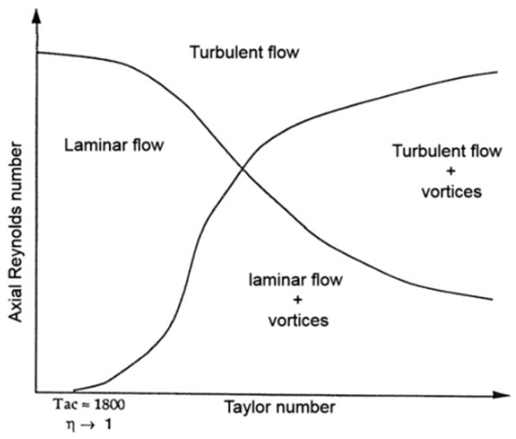
The flow structure results from the superposition of two mechanisms, the first related to the effects of rotation and the second to the axial flow. From these mechanisms, two main transitions can be distinguished: the transition from laminar to turbulent flow with increasing axial velocity, and the transition from turbulent flow to the appearance of vortex structures above the critical rotational speed ω of the cylinder. The combination of these combined phenomena was described by Kaye and Elgar (1958) [40] (Figure 4), who decompose into four mains flow regimes:
  • Laminar flow,
  • Laminar flow with Taylor structures,
  • Turbulent flow,
  • Turbulent flow with Taylor structures.
Kaye and Eglar (1958) [40] cited by [41] showed with an experimental study and a hot wire anemometer that axial flow has a stabilizing effect on Taylor structures. The onset of the first instabilities occurs for larger cylinder rotation speeds ω (higher Taylor number) than a simple Taylor–Couette flow. The importance of rotational velocity in flow transitions is important and is the subject of many studies.
The flow characterization has been established by various works inventoried on the subject [42,43,44] for 0 R e a 10 4 and 0 T a 10 6 . A study with larger axial and Taylor Reynolds numbers was also performed [45] ( 2 × 10 4 R e a 3 × 10 4 , 4 × 10 7 T a 2 × 10 9 ). The authors investigated the influence of physical phenomena such as the rotation speed of the inner cylinder on the transfer phenomena as a function of the identified flow regime. Experimental results [43] show that the transition between a turbulent flow and a turbulent flow containing Taylor cells is punctuated by a transition zone and not distinctly separated. Jakoby et al. (1999) [45] also confirmed the existence of a transition zone between a flow with and without Taylor cells.
A more detailed analysis of the transitions was performed experimentally [46] cited by [41]. This experimental study was performed for low Taylor numbers ( T a < 3000 ) and very low Reynolds numbers ( R e a < 540 ) in the context of a weak annular gap η = 0.885 and Γ = 41 . They observed a significant number of flow regimes ranging from laminar to turbulent flow. The limited description at low Reynolds and Taylor numbers is presented by a detailed flow mapping (Figure 5).
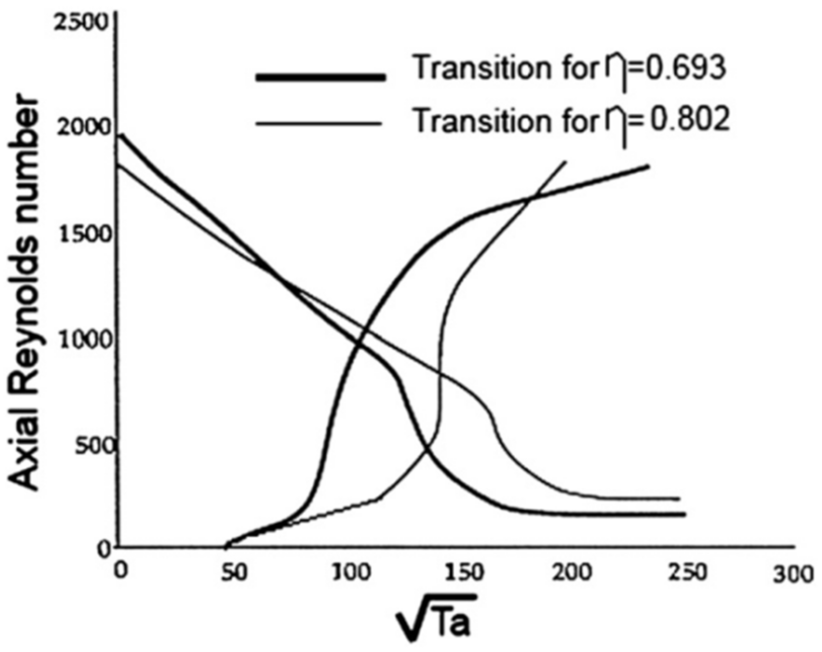
Finally, several authors have focused on the parameters influencing the transition between flow with and without Taylor cells. The size of the annulus ( Γ ,   η ) appears to play an important role in the flow transitions (Figure 6). Kaye and Eglar (1958) [40] cited by [41] determined and compared the major flow transitions for two annular space thicknesses η = 0.693 and 0.802 . For very low axial flow or Reynolds number ( R e a < 100 ), the size of the annular space does not appear to influence the transitions. In contrast, for high axial Reynolds number, increasing the annulus size seems to alter the flow transition. Taylor cells appear for lower angular velocity of the inner cylinder. Similar results have also been observed [45] on the transition between a flow with and without Taylor cells.
In contrast to the results of Kaye and Eglar (1958) [40], other work [47] showed that widening the annulus stabilized the flow, with an appearance of Taylor cells for larger Taylor numbers. This contradiction between the authors can be explained by the effect of L and Γ on the development of the flow and specifically the axial velocity profile. Increasing R e a has the effect of increasing the flow developing region, and thus delaying along the z -axis the appearance of the first Taylor cells [48].
Fénot et al. (2011) [49] performed a literature review on heat transfer in Taylor–Couette, and Taylor–Couette–Poiseuille flows. They concluded that:
“Despite the considerable amount of studies carried out on Taylor-Couette-Poiseuille flow, the large number of influential factors leaves many questions regarding their impacts on flow dynamics and heat transfers”. Indeed, the results published in the literature depend largely on the study configuration, and do not yet provide a sufficient basis for large-scale extrapolation.

2.3. Numerical Simulation in Taylor–Couette–Poiseuille Flow

Numerical studies of Taylor–Couette–Poiseuille flow cover different configurations of the flow and have already received much attention due to the three-dimensional boundary layer of the flow. Some of the different numerical studies of the Taylor–Couette–Poiseuille flow available in the literature are presented in Table 2. The experimental studies [50,51] provide valuable experimental data on the influence of the rotating inner wall on the axial flow in an annular space. These authors [50,51] extracted the various components of mean velocity and turbulent stresses in an annular space possessing a large shape factor ( η = 0.5 ) and a large aspect ratio ( Γ = 98 244 ; N ). These experiments included the study of the effect of the nature of the Newtonian and shear-thinning fluid on the flow. Finally, the large aspect ratio, Γ , used by the authors during their experiments allows for the assumption of fully developed flow in the axial direction. These experimental data [50,51] were used to validate most of the numerical experiments in Taylor–Couette–Poiseuille flow recapped in Table 2.
Authors [52,53] numerically investigated, from DNS [52] and LES [53], the effect of the radius of curvature of two annular geometries ( η = 0.1   et   0.5 ) upon the near wall turbulent structures in a given axial flow ( R e a = 4450 ). In this study, the outer and inner cylinders are stationary. The authors showed a change in the characteristic of the turbulent structures at the outer wall due to the change in the radius of curvature. Later, Jung and Sung (2006) [54] extended the numerical study [52] with a rotating inner wall. The rotation parameter N = R e t / R e a studied by the authors was 0.429 . They were interested in the study of coherent structures located in the inner wall and their changes compared to the study of Chung et al. (2002) [52] due to the influence of centrifugal forces. The authors found an increase in near-wall turbulence with an increase in the ejection of coherent structures into the flow.
Chung and Sung (2005) [53] performed a numerical study by Large Eddy Simulation (LES). The LES simulation was performed using the experimental setup from [50] ( η = 0.5 and = 0.214 ,   0.429 and 0.858 for an axial Reynolds number R e a = 4450 ). They showed the influence of the inner cylinder rotation velocity on the destabilization of the turbulent structures in the near wall region.
Large-Eddy Simulation was also used [55] to characterize a Taylor–Couette–Poiseuille flow with a shape factor η = 0.5 . The study regards a rotating outer cylinder, which is rarer in the literature. This study focuses on the effect of rotation for a wide range of studies of the rotation parameter N , ranging from 0.5 to 4 . The authors focused on studying the effect of the outer cylinder velocity on the mean flow, turbulence statistics and vortex structures (Q-Criterion). A significant change in the turbulent structures was observed for N = 2.8 . Indeed, the turbulence is thus reduced while helical vortex structures are perceptible in the near outer wall. According to the authors [55], this change is attributed to the centrifugal turbulence generated in the near wall dominating the inertial forces of the flow. For a higher rotation rate ( N = 4 ), the flow stabilizes and becomes laminar with the appearance of Taylor–Couette vortex structures usually observed in a Taylor–Couette flow without axial flow.
Poncet et al. (2014) [56] performed Large-Eddy Simulations of a Taylor–Couette–Poiseuille flow with rotation of the inner cylinder in a narrow annular space, but for large values of the rotational parameter N ( 1.49 N 6.71 ). Initially, the authors compared their numerical results favorably on the experimental data [50], and on the data from Large Eddy Simulations [53]. Next, the authors extended their work to real operating conditions ( η = 0.889 ,   Γ = 10 ) to study the influence of the rotation parameter N on the mean flow and on the turbulence statistics. The authors were also interested in the nature of the coherent structures appearing in the boundary layer and their influences on the heat transfers. The authors Poncet et al. (2014) [56] observed that the turbulence is mainly concentrated in the boundary layer of the flow. A small dissymmetry is noticeable in the Reynolds stress distribution at the rotating cylinder boundary layer, telling us that the inner cylinder boundary layer is more chaotic than that observed on the outer cylinder. Rotation of the inner cylinder appears to destabilize the flow and have an opposite effect compared to the results obtained by Hadziabdic et al. (2013) [55] of stabilizing the flow with increasing rotation of the outer cylinder.
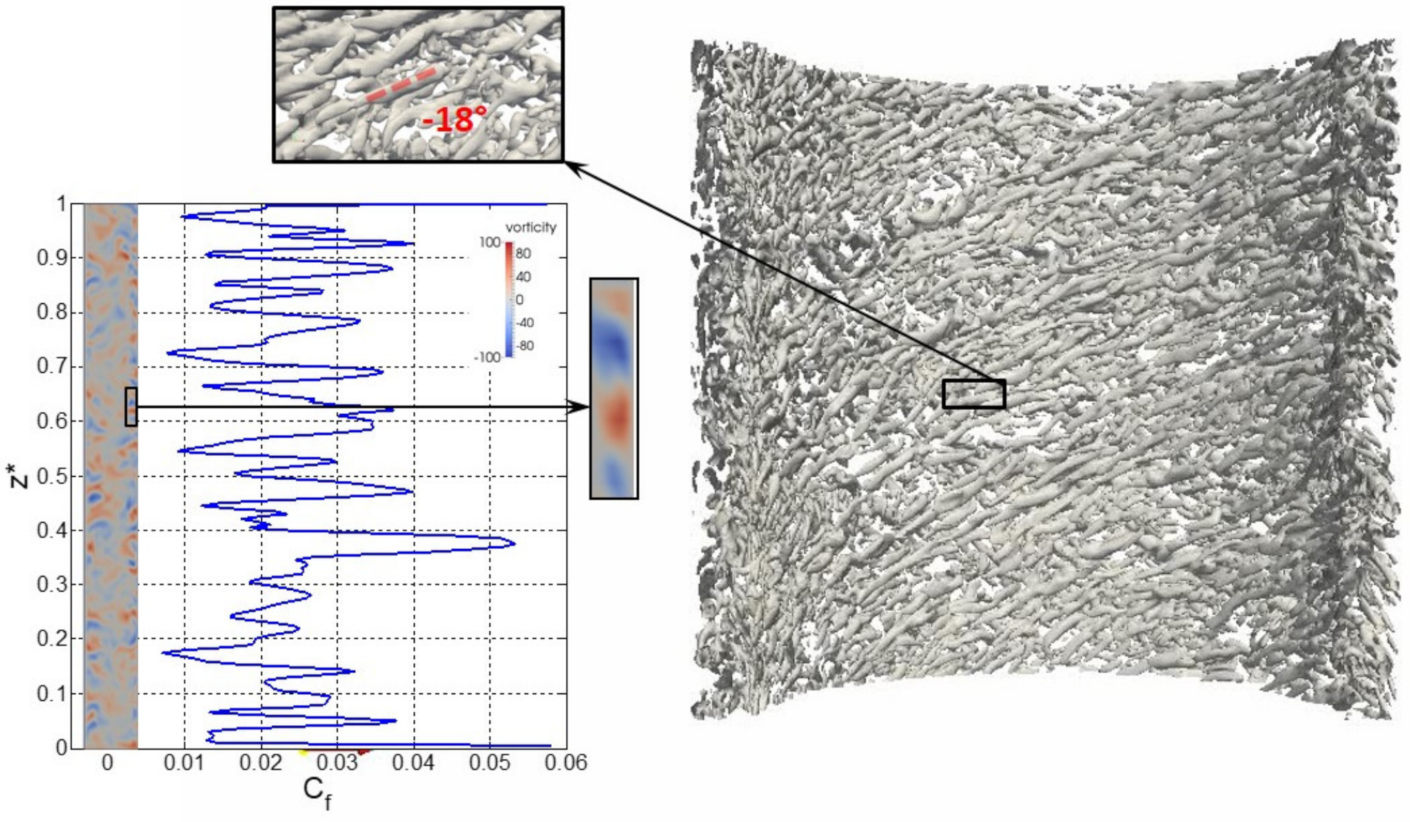
In the literature, there are a few numerical simulations of Taylor–Couette–Poiseuille flow using the Reynolds decomposition known as RANS (Reynolds Averaged Navier–Stokes). The k ε turbulence model is the most commonly used model in computational fluid mechanics to simulate the mean flow under turbulent conditions. Nevertheless, the predictions from a kε turbulence model seem to deviate to the literature results in the case of a Taylor–Couette–Poiseuille flow. Indeed, in a flow where turbulent transport and no equilibrium effects are important, the assumption of turbulent viscosity used by the k ε model is no longer valid, and the results of the turbulent viscosity model may turn out to be not accurate [57,58]. Some authors [59] have used a k ε turbulence model, but it shows large discrepancies compared to the experimental data of [51]. Compared to turbulent viscosity models, Reynolds stress models (RSM) naturally include curvature effects, abrupt changes in velocity stress, and secondary flows. The Reynolds stress model solves the transport equations for each Reynolds stress u i u j and dissipation rate ε at each time step. The authors of [57] performed steady state RANS simulations based on an innovative Reynolds stress model sensitized to rotational effects. A study [57] has compared their results favorably on the experimental data of Escudier and Gouldson (1995) [51], and extended their work on real operating conditions ( η = 0.961 ,   Γ = 77 ) including non-isothermal flow in a wide range of Reynolds numbers ( 0 R e a 4870 ,   3744 R e w 37,443 ). Recent work addresses numerical simulations from various methods to understand the role of the wall turbulence properties in the heat transfer results in non-isothermal conditions. Ohasawa et al. (2016) [60] used LES simulation, showing a large contribution of the turbulent transport term on the Nusselt number results. Mehrez et al. (2019) [61] used the Lattice Boltzmann method to assess the importance given to the initial conditions for Taylor–Couette–Poiseuille flow characterization. Piton et al. 2022 [62] used LES method to characterize the turbulent kinetic energy transport in the near wall region for heat recovery system application (Figure 7). Therefore, the importance to study the rotational annular duct in a non-isothermal condition has a practical interest (see Table 1). The next section is aimed to cover the main fundamental works that have included the heat transfer phenomenon.

3. Non-Isothermal Condition

We can report a large amount of convection studies that investigated annular ducts for which constant temperature or constant heat fluxes is imposed at the inner or outer boundaries. According to a careful sorting extracted from the literature, the present section addresses a report of the main scaling laws of the heat transport in rotating annular ducts.
In natural and mixed regimes of convection, the buoyancy force driven by the difference of fluid density in the annulus cannot be neglected. The momentum and buoyancy induced flows increase the complexity of the hydrodynamics behavior. It implies a large variety of flow patterns, from spiral-type at low rotational speed to Taylor Vortex-type at the dominant torque effect [63]. The Rayleigh number, Ra, is the dimensionless number allowing us to express the importance of the buoyancy force driven by the difference of temperature. It is defined according to the following relationship:
R a = g β ( T R E F T W a l l ) ( D ) 3 ν κ
where T w a l l is the hot temperature source at the inner or outer wall, T R E F can be varied according to the author. Generally, it corresponds to the fluid temperature probed in the vicinity of the inner or outer wall. g is the gravity, D the external cylinder diameter, β , ν and κ are, respectively, the dilatation coefficient, the kinematic viscosity and the thermal diffusivity of the fluid.
At a low R a number below Rac = 400 Γ, the buoyancy-induced flow are weak [16], a purely diffusive regime is considered. The Nusselt number, which characterizes heat transfer, is solely dependent on the geometry of the annular cell [64] and defined by:
N u = q D h ( T R E F T W a l l ) λ = 2 ( R e R i R i ) ln [ 1 + ( R e R i R i ) ]
With q the heat flux density, D h = 2 e is the hydraulic diameter and λ the thermal conductivity.
From R a > R a c and T a < T a c the onset of convection in a closed-gap system is governed by the buoyancy force revealing scaling law of type Nu~Raα~1/3 [16] in such way that:
N u = 0.22 R a 0.29  
The mechanism of transport would support the theory of Rayleigh–Bernard convection where the two thermal boundaries (inner and outer cylinders) are the engine of the fluid motion. In open-gap, the end-effects are not negligible, developing flow and additional turbulent transfer of momentum energy. The momentum kinetic energy coupled to the buoyancy forces from the thermal kinetic energy have shown that the scaling law is of the type Nu~Ra0.38<α<0.5 [65,66]. The scaling exponent, α, is variable in the literature [66]. Recent works seem shown that it depends essentially on the origin of the turbulent transport mechanisms, which are summarized by Swirling-type [14] and Rayleigh-type flow behaviors [67]. Thus, in the more recent works, effective Reynolds numbers are preferred to the Rayleigh number by adjusting the scaling exponent in such a way that N u ~ R e e f f γ with Reeff depending on Ra [68]. Recent results conclude to an exponent value close to γ~0.6 in axial [68] or radial heat fluxes conditions [14] such as:
N u = 0.3 Re eff 0.6
DNS modelling and further experiments appear as a safe bet to overcome the physical complexity linked to multiple turbulent flow states and the coupling phenomena of heat and momentum transfer [63,68]. A set of correlations are depicted in Table 3.
In forced regime of convection at large Ta > Tac, two reviewing papers were recapped most of the papers published before 2010. Howey et al. (2012) [69] were interested in air gap convection in rotating electrical machines, giving some results based on popular Nu-correlation showing that large gap ratios and higher rotational speed give better performance than smaller rotating machines. Fenot et al. (2011) [49] made a recapitulation of the main correlations for convective heat transfer in closed and open cylindrical gaps. The conjugated inertial effects of the axial and rotational flows lead to a complex behavior and scattered equation in terms of Nu = f(Rea,Rew). Numerical works performed in the last decade have allowed understanding the role of the vortices transport (see Figure 7) on the heat transfer mechanisms [56,62]. It has resulted in a new set of correlations in terms of skin-friction factor and heat transfer in case of optimized geometries of TCP [70]. A set of correlations are depicted in Table 4.

4. Conclusions

To conclude, the objective of this review was to establish an overview of the theory development, the applications and the modelling aspects of the heat transport into rotating annular ducts.
The governing parameters of control were found to be widespread according to energy systems. Gap thickness, length of cylinders and rotational velocity can vary in an extreme way if gases, liquid or even non-Newtonian fluid are considered. From such a variety of configurations, it has resulted in numerous works in the literature to cover the entire flow regimes in Taylor–Couette (TC) geometry. The prediction of the instabilities according to the magnitude of the rotational velocity, shape factor and gap thickness remains a technological and scientific issue. The Taylor–Couette–Poiseuille (TCP) configuration has opened the way to expand laminar and turbulent flow regimes in order to better control the flow instabilities apparition with an imposed axial flow rate. Nevertheless, such a configuration reaches no less than 12 flow regimes according to the imposed rotational velocity and axial flow rates. Thus, many numerical results of the literature have been presented using various methods for turbulence characterization in TCP flow. It has been shown that LES seems a good candidate to model the flow dynamics in such geometries. LES is well adapted to characterize the near-wall region, where the transport of the turbulent kinetic energy is responsible for the heat transfer optimization, or defect, according to the importance of the axial flow rates.
In non-isothermal conditions, several works have been established for which the present review proposes to distinguish:
-
The open- and closed-gap;
-
The radial and axial heat flux densities.
Depending on the configuration, many correlations of the Nu number could be listed. In the natural regime of convection, the dependence in Ra0.3 seems to be valid. In the mixed and forced regime of convection, respectively, it seems that the dependence in R e e f f γ ~ 0.6 and R e e f f γ ~ 0.8 finds consensus.
The future research direction will aim at an explanation of these exponents’ values for heat transport scaling relationships. Only a conjugated effort of experience and modelling will be able to determine the origin of the turbulent flow mechanisms (i.e., buoyancy and/or inertia) responsible for the heat transport in the near wall region.

Author Contributions

Conceptualization, M.P. and F.H.; methodology, F.H.; software, M.P.; validation, M.P., F.H. and O.L.C.; formal analysis, M.P.; investigation, M.P.; resources, B.C.; data curation, F.H.; writing—original draft preparation, M.P.; writing—review and editing, F.H.; visualization, M.P.; supervision, F.H. and O.L.C.; project administration, F.H.; funding acquisition, B.C. All authors have read and agreed to the published version of the manuscript.

Funding

This research received no external funding.

Data Availability Statement

Not applicable.

Conflicts of Interest

The authors declare no conflict of interest.

Nomenclature

Symbols
DmExternal diameter of the cylinder
DhmHydraulic diameter
e mThickness of the annular space (=Re- Ri)
gm.s−2Gravity
km2.s−2Turbulent kinetic energy
LmLength of the cylinders
N-Rotational parameters (= R e t / R e a )
Nu-Nusselt number
qW/m2Wall heat density
RimInternal raduis
RemExternal raduis
Ra-Rayleigh Number
Rea-Axial Reynolds number
Reeff-Effective Reynolds number
Rew-Rotational Reynolds number
T°KTemperature
T W a l l °KWall temperature
Ta-Taylor number
Tac-Critical Taylor number
U θ   m.s−1Tangential or spanwise velocity component
U z   m.s−1Axial or streamswise velocity component
u i u j m2.s−2Reynolds stress tensor
r , θ , z   (m, rad, m)Cylindrical coordinate
r * -Dimensionless radial coordinate ( = r R i ) / ( R e R i )
z * -Dimensionless axial coordinate (=z/L)
Greek symbols
β °K−1Thermal dilatation coefficient
ε m3.s−2Turbulent kinetic energy dissipation rate
η -Shape factor ( = R i / R e )
κ m.s−2Thermal diffusivity
λ W.m−1.K−1Themal conductivity
Γ -Aspect ratio ( = L / e )
ν m.s−2Kinematic viscosity
φ rad
Φ v   -Volume fraction
Φ w   -Mass fraction
ω rad.s−1Angular velocity of the cylinder
ω c   rad.s−1Crictical angular velocity
Abbreviations
DNS Direct Numerical Simulation
LB Lattice Boltzman method
LDA Laser Doppler Anemometry
LES Large Eddy Simulation
RANS Reynolds Averaged Navier Stokes
TC Taylor-Couette
TCP Taylor-Couette-Poiseuille
k ε   Turbulent closure model

References

  1. Bouafia, M.; Bertin, Y.; Saulnier, J.-B.; Ropert, P. Analyse expérimentale des transferts de chaleur en espace annulaire étroit et rainuré avec cylindre intérieur tournant. Int. J. Heat Mass Transf. 1998, 41, 1279–1291. [Google Scholar] [CrossRef]
  2. Yoo, W.; Jeon, S.; Son, C.; Yang, J.; Ahn, D.; Kim, S.; Hwang, K.; Ha, S. Full surface heat transfer characteristics of rotor ventilation duct of a turbine generator. Appl. Therm. Eng. 2016, 94, 385–394. [Google Scholar] [CrossRef]
  3. Caputo, A.C.; Pelegagge, P.M.; Salini, P. Performance modeling of radiant heat recovery exchangers for rotary kilns. Appl. Therm. Eng. 2011, 31, 2578–2589. [Google Scholar] [CrossRef] [Green Version]
  4. Swann, P.B.; Russel, H.; Jahn, I.H. Taylor-Couette-Poiseuille flow heat transfer in a high Taylor number test rig. J. Glob. Power Propuls. Soc. 2021, 5, 126–147. [Google Scholar] [CrossRef]
  5. Lorusso, P.; Martelli, E.; Del Nevo ADel Narcisi, V.; Giannetti, F.; Tarantino, M. Development of a PbLi heat exchanger for EU DEMO fusion reactor: Experimental test and system code assessment. Fusion Eng. Des. 2021, 169, 112462. [Google Scholar] [CrossRef]
  6. Poncet, S.; Schiestel, R. Numerical modeling of heat transfer and fluid flow in rotor–stator cavities with throughflow. Int. J. Heat Mass Transf. 2007, 50, 1528–1544. [Google Scholar] [CrossRef] [Green Version]
  7. Nemri, M.; Charton, S.; Climent, E. Mixing and axial dispersion in Taylor-Couette flows: The effect of the flow regime. Chem. Eng. Sci. 2015, 139, 109–124. [Google Scholar] [CrossRef] [Green Version]
  8. Abou-Ziyan, H.; Ameen, R.; Elsayed, K. Fluid flow and convection heat transfer in concentric and eccentric cylindrical annuli of different radii ratios for Taylor-Couette-Poiseuille flow. Adv. Mech. Eng. 2021, 13, 1–22. [Google Scholar] [CrossRef]
  9. Avila, K.; Moxey, D.; De Lozar, A.; Avila, M.; Barkley, D.; Hof, B. The onset of turbulence in pipe flow. Science 2011, 33, 192–196. [Google Scholar] [CrossRef] [Green Version]
  10. Grossmann, S.; Lohse, D.; Sun, C. High Reynolds numbers Taylor-Couette turbulence. Annu. Rev. Fluid Mech. 2016, 48, 53–80. [Google Scholar] [CrossRef]
  11. Leclercq, C.; Partridge, J.; Augier, P.; Dalziel, S.; Kerswell, R. Using stratification to mitigate end effects in quasi-Keplerian Taylor-Couette flow. J. Fluid Mech. 2016, 791, 608–630. [Google Scholar] [CrossRef]
  12. Naimi, M.; Devienne, R.; Lebouche, M. Etude dynamique et thermique de l’écoulement de Couette-Taylor-Poiseuille; cas d’un fluide présentant un seuil d’´écoulement. Int. J. Heat Mass Transf. 1990, 33, 381. [Google Scholar] [CrossRef]
  13. Jenny, M.; De Richter, S.K.; Louvet, N.; Skali-Lami, S.; Dossmann, Y. Taylor-Couette instability in thixotropic yield stress fluids. Phys. Rev. Fluids Am. Phys. 2017, 2, 023302. [Google Scholar] [CrossRef] [Green Version]
  14. Huchet, F.; Piton, M.; Del Barrio, A.; Le Corre, O.; Cazacliu, B. Air-cooled heat exchanger applied to external rotary kiln wall in forced and natural draft. Energy Convers. Manag. 2017, 154, 517–525. [Google Scholar] [CrossRef]
  15. Nouri-Borujerdi, A.; Nakhchi, M.E. Heat transfer enhancement in annular flow with outer grooved cylinder and rotating inner cylinder: Review and experiments. Appl. Therm. Eng. 2017, 120, 257–268. [Google Scholar] [CrossRef]
  16. Vahl Davis, G.; Thomas, R.W. Natural convection between concentric vertical cylinders. Phys. Fluids Suppl. II 1969, 12, 198–207. [Google Scholar]
  17. Sorour, M.M.; Coney, J.E.R. The effect of temperature gradient on the stability of flow between vertical, concentric, rotating cylinders. J. Mech. Eng. Sci. 1979, 21, 403–409. [Google Scholar] [CrossRef]
  18. Lopez, J.M.; Marques, F.; Avila, M. Conductive and convective heat transfer in fluids flows between differentially heated and rotating cylinder. Int. J. Heat Mass Transf. 2015, 90, 959–967. [Google Scholar] [CrossRef] [Green Version]
  19. Dawood, H.K.; Mohammed, H.A.; Azwadi Che Sidik, N.; Munisamy, K.M.; Wahid, M.A. Forced, natural and mixed-convection heat transfer and fluid flow in annulus: A review. Int. Commun. Heat Mass Transf. 2015, 62, 45–57. [Google Scholar] [CrossRef]
  20. Avramenko, A.A.; Tyrinov, A.I.; Shevchuk, I.V.; Dmitrenko, N.P. Dean instability of nanofluids with radial temperature and concentration non-uniformity. Phys. Fluids 2016, 28, 034104. [Google Scholar] [CrossRef]
  21. Davaille, A.; Gueslin, B.; Massmeyer, A.; Giuseppe, E.D. Thermal instabilities in a yield stress fluid: Existence and morphology. J. Non-Newton. Fluid Mech. 2013, 193, 144–153. [Google Scholar] [CrossRef]
  22. Varé, T.; Nouar, C.; Métivier, C.; Bouteraa, M. Stability of hexagonal pattern in Rayleigh–Bénard convection for thermodependent shear-thinning fluids. J. Fluid Mech. 2020, 905, A33. [Google Scholar] [CrossRef]
  23. Peixinho, J.; Desaubry, C.; Lebouché, M. Heat transfer of a non-Newtonian fluid (Carbopol aqueous solution) in transitional pipe flow. Int. J. Heat Mass Transf. 2008, 51, 198–209. [Google Scholar] [CrossRef]
  24. Maleki, A.; Frigaard, I.A. Axial dispersion in weakly turbulent flows of yield stress fluids. J. Non-Newton. Fluid Mech. 2016, 235, 1–19. [Google Scholar] [CrossRef]
  25. Tso, C.P.; Mahulikar, S.P. Combined evaporating meniscus-driven convection and radiation in annular microchannels for electronics cooling application. Int. J. Heat Mass Transf. 2000, 43, 1007–1023. [Google Scholar] [CrossRef]
  26. Ozerdem, B. Measurement of convective heat transfer coefficient for a horizontal cylinder rotating in quiescent air. Int. Commun. Heat Mass Transf. 2000, 27, 389–395. [Google Scholar] [CrossRef] [Green Version]
  27. Harmand, S.; Pellé, J.; Poncet, S.; Shevchuk, I.V. Review of fluid flow and convective heat transfer within rotating disk cavities with impinging jet. Int. J. Therm. Sci. 2013, 67, 1–30. [Google Scholar] [CrossRef] [Green Version]
  28. Cavazzuti, M.; Agnani, E.; Corticelli, M.A. Optimization of a finned concentric pipes heat exchanger for industrial recuperative burners. Appl. Therm. Eng. 2015, 84, 110–117. [Google Scholar] [CrossRef]
  29. Douaire, M.; Mercade, M.; Morchain, J.; Loubière, P. A unique phenotypic modification of Lactococcus lactis cultivated in a couette bioreactor. Biotechnol. Bioeng. 2011, 108, 559–571. [Google Scholar] [CrossRef]
  30. Seddegh, S.; Joybari, M.M.; Wang, X.; Haghighat, F. Experimental and numerical characterization of natural convection in a vertical shell-and-tube latent thermal energy storage system. Sustain. Cities Soc. 2017, 35, 13–24. [Google Scholar] [CrossRef]
  31. Lepiller, V.; Goharzadeh, A.; Prigent, A.; Mutabazi, I. Weak temperature gradient effect on the stability of the circular Couette flow. Eur. Phys. J. B 2008, 61, 445–455. [Google Scholar] [CrossRef]
  32. Farias, M.H.; Braga, C.V.M.; Souza Mendes, P.R. Heat transfer coefficients for the laminar fully developed flow of viscoplastic liquids through annuli. Int. J. Heat Mass Transf. 2009, 52, 3257–3260. [Google Scholar] [CrossRef]
  33. Ahmed, H.E.; Ahmed, M.I. Thermal performance of annulus with its applications; A review. Renew. Sustain. Energy Rev. 2017, 71, 170–190. [Google Scholar] [CrossRef]
  34. Taylor, G.I. Stability of viscous liquid contained between two rotating cylinders. Philos. Trans. R. Soc. Lond. Ser. A 1923, 223. [Google Scholar]
  35. Coles, D. Transactions in circular Couette flows. J. Fluid Mech. 1965, 21, 385–425. [Google Scholar] [CrossRef] [Green Version]
  36. Fenstermacher, P.R.; Swinney, H.L.; Gollub, J.P. Dynamical instabilities and the transition to chaotic Taylor vortex flow. J. Fluid Mech. 1979, 94, 103–128. [Google Scholar] [CrossRef] [Green Version]
  37. Andereck, D.; Liu, S.S.; Swinney, H.L. Flow regimes in a circular Couette system with independently rotating cylinders. J. Fluid Mech. 1986, 164, 155–183. [Google Scholar] [CrossRef] [Green Version]
  38. Esser, A.; Grossmann, S. Analytic expression for Taylor-Couette stability boundary. Physic Fluids 1996, 8, 1814. [Google Scholar] [CrossRef] [Green Version]
  39. Domanski, J. Determination of the parameters of fluid motion in Taylor-Couette Flow. Tech. Sci. Pap. Rep. 2006, 9, 73–78. [Google Scholar]
  40. Kaye, J.; Elgar, E.C. Modes of adiabatic and diabatic fluid flow in an annulus with an inner rotating cylinder. Trans. ASME 1958, 80, 753–765. [Google Scholar] [CrossRef]
  41. Piton, M. Heat Recovery Exchanger Applied to the Rotary Kiln Equipment. Ph.D. Thesis, Ecole des Mines de Nantes, Nantes, France, 6 November 2015. [Google Scholar]
  42. Chandrasekhar, S. The stability of spiral flow between rotating cylinders. Proc. R. Soc. Lond. Ser. A 1962, 265, 188–197. [Google Scholar]
  43. Yamada, Y. Resistance of a flow through an annulus with an inner rotating cylinder. Bull. JSME 1962, 5, 302–310. [Google Scholar] [CrossRef] [Green Version]
  44. Polkowski, J.W. Turbulent flow between coaxial cylinders with the inner cylinder rotating. J. Eng. Gas Turbines Power 1984, 106, 128–135. [Google Scholar] [CrossRef]
  45. Jakoby, R.; Kim, S.; Wittig, S. Correlations of the convection heat transfer in annular channels with rotating inner cylinder. J. Eng. Gas Turbines Power 1999, 121, 670–677. [Google Scholar] [CrossRef]
  46. Lueptow, R.M.; Docter, A.; Min, K. Stability of axial flow in an annulus with a rotating inner cylinder. Phys. Fluids 1992, A4, 2446–2456. [Google Scholar] [CrossRef] [Green Version]
  47. Wan, C.C.; Coney, J.E.R. Transition modes in adiabatic spiral vortex flow in narrow and wide annular gaps. Int. J. Heat Fluid Flow 1980, 2, 131–138. [Google Scholar] [CrossRef]
  48. Molki, M.; Astill, K.N.; Leal, E. Convective heat-mass transfer in the entrance region of a concentric annulus having a rotating inner cylinder. Int. J. Heat Fluid Flow 1990, 11, 120–128. [Google Scholar] [CrossRef]
  49. Fénot, M.; Bertin, Y.; Dorignac, E.; Lalizel, G. A review of heat transfer between concentric rotating cylinders with or without axial flow. Int. J. Therm. Sci. 2011, 50, 1138–1155. [Google Scholar] [CrossRef]
  50. Nourri, J.M.; Whitelaw, J.H. Flow of Newtonian and non-Newtonian fluids in a concentric annulus with rotation of inner cylinder. J. Fluid Eng. 1994, 116, 821–827. [Google Scholar] [CrossRef]
  51. Escudier, M.P.; Gouldson, I.W. Concentric annular flow with centerbody rotation of a Newtonian and a shear-thinnig liquid. Int. J. Heat Fluid Flow 1995, 16, 156–162. [Google Scholar] [CrossRef]
  52. Chung, S.Y.; Rhee, G.H.; Sung, H.J. Direct numerical simulation of turbulent concentric annular pipe flow. Part. 1: Flow field. Int. J. Heat Fluid Flow 2002, 23, 426–440. [Google Scholar] [CrossRef]
  53. Chung, S.Y.; Sung, H.J. Large-eddy simulation of turbulent flow in concentric annulus with rotation of an inner cylinder. Int. J. Heat Fluid Flow 2005, 26, 191–203. [Google Scholar] [CrossRef]
  54. Jung, S.Y.; et Sung, H.J. Characterization of the three-dimensional turbulent boundary layer in a concentric annulus with a rotating inner cylinder. Phys. Fluids 2006, 18, 115102. [Google Scholar] [CrossRef] [Green Version]
  55. Hadziabdic, M.; Hanjalic, K.; Mullyadzhanov, R. LES of turbulent flow in a concentric annulus with rotating outer wall. Int. J. Heat Fluid Flow 2013, 43, 74–84. [Google Scholar] [CrossRef]
  56. Poncet, S.; Viazzo, S.; Oguic, R. Large eddy simulation of Taylor-Couette-Poiseuille flows in a narrow-gap system. Phys. Fluids 2014, 26, 105108. [Google Scholar] [CrossRef]
  57. Poncet, S.; Haddadi, S.; Viazzo, S. Numerical modeling of fluid flow and heat transfer in a narrow Taylor-Couette-Poiseuille system. Int. J. Heat Fluid Flow 2011, 32, 128–144. [Google Scholar] [CrossRef] [Green Version]
  58. Pawar, S.B.; Thorat, B.N. CFD simulation of Taylor-Couette flow in scraped surface heat exchanger. Chem. Eng. Res. Des. 2012, 90, 313–322. [Google Scholar] [CrossRef]
  59. Naser, A. Prediction of Newtonian and non-Newtonian flow through concentric annulus with centerbody rotation. In Proceedings of the 1st International Conference on CFD in Mineral and Metal Processing and Power Generation, Melbourne, Australia, 3–4 July 1997. [Google Scholar]
  60. Ohsawa, A.; Murata, A.; Iwamoto, K. Through-flow effects on Nusselt number and torque coefficient in Taylor-Couette-Poiseuille flow investigated by large eddy simulation. J. Therm. Sci. Technol. 2016, 11, 1–12. [Google Scholar] [CrossRef] [Green Version]
  61. Mehrez, I.; Gheith, R.; Aloui, F.; Nasrallah, S.B. Theoretical and numerical study of Couette-Taylor flow with an axial flow-using lattice Boltzmann method. Int. J. Numer. Meth. Fluids 2019, 90, 427–441. [Google Scholar] [CrossRef]
  62. Piton, M.; Huchet, F.; Cazacliu, B.; Le Corre, O. Numerical Turbulent Flow Analysis through a Rotational Heat Recovery System. Energies 2022, 15, 6792. [Google Scholar] [CrossRef]
  63. Guillerm, R.; Kang, C.; Savaro, C.; Lepiller, V.; Prigent, A.; Yang, K. Flow regimes in a vertical Taylor-Couette system with a radial thermal gradient. Phys. Fluids 2015, 27, 094101. [Google Scholar] [CrossRef]
  64. Bjorklund, I.; Kays, W. Heat transfer between concentric rotating cylinders. Trans. ASME J. Heat Transf. 1959, 84, 97–105. [Google Scholar] [CrossRef]
  65. Vafai, K.; Desai, C.P.; Iyer, S.V.; Dyko, M.P. Buoyancy induced convection in a narrow open-ended annulus. J. Heat Transf. 1997, 19, 483–494. [Google Scholar] [CrossRef]
  66. Grossman, S.; Lohse, D. Multiple scaling in the ultimate regime of thermal convection. Phys. Fluids 2011, 23, 045108. [Google Scholar] [CrossRef]
  67. Boffeta, G.; Mazzino, A. Incompressible Rayleigh-Taylor turbulence. Annu. Rev. Fluid Mech. 2017, 49, 119–143. [Google Scholar] [CrossRef] [Green Version]
  68. Leng, X.Y.; Zhong, J.Q. Mutual coherent structures for heat and angular momentum transport in turbulent Taylor-Couette flows. Phys. Rev. Fluids 2022, 7, 043501. [Google Scholar] [CrossRef]
  69. Howey, D.A.; Childs, P.R.N.; Holmes, A.S. Air-Gap convection in rotating electrical machines. IEEE Trans. Ind. Electron. 2012, 59, 1367–1375. [Google Scholar] [CrossRef]
  70. Nouri-Borujerdi, A.; Nakhchi, M.E. Optimization of the heat transfer coefficient and pressure drop of Taylor-Couette-Poiseuille flows between an inner rotating cylinder and an outer grooved stationary cylinder. Int. J. Heat Mass Transf. 2017, 108, 1449–1459. [Google Scholar] [CrossRef]
  71. Becker, K.; Kaye, J. The influence of a radial temperature gradient on the instability of fluid flow in an annulus with inner rotating cylinder. Trans. ASME 1962, 80, 79–90. [Google Scholar] [CrossRef]
  72. Gazley, C. Heat-Transfer Characteristics of the Rotational and Axial Flow between Concentric Cylinders. J. Turbomach. 1958, 80, 79–90. [Google Scholar] [CrossRef]
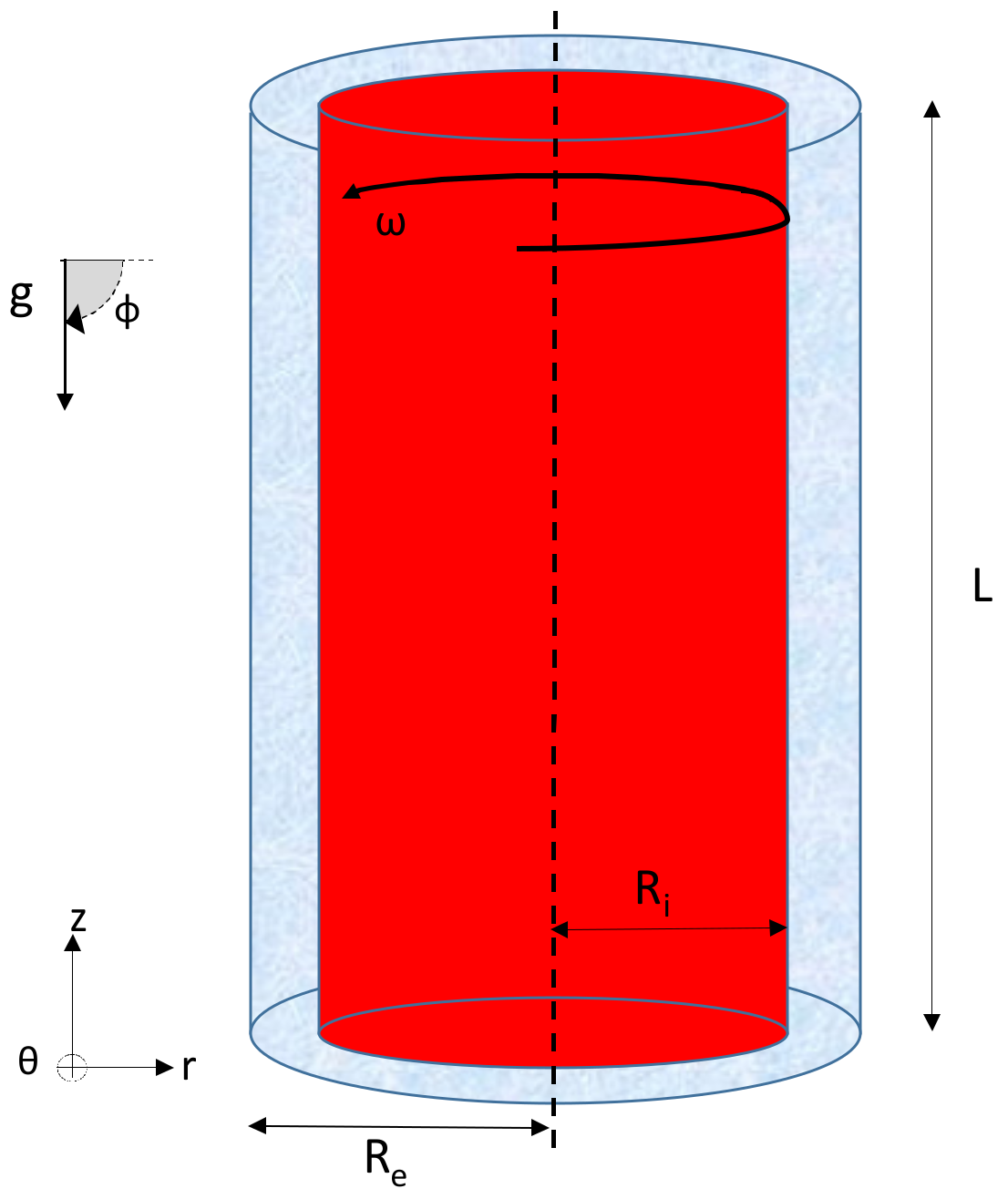
Figure 1. Position of the problem: two concentric cylindrical surfaces of inner and external radius, Ri and Re, and of length, L, are inclined at an angle φ with the gravity. The rotation can be exerted from the inner (drawn here) or from the external cylinder at an angular velocity, ω . The heat gradient, T / r , can be imposed from any wall surface (the inner cylinder is chosen here), while the fluid motion is flowing into the gap, e = R e R i .
Energies 15 08633 g001
Figure 2. From bottom to top; Taylor vortices, Dean Vortices, and Görtler Vortices at a concave wall.
Energies 15 08633 g002
Figure 4. Flow regimes as a function of axial Reynolds number and Taylor number [41].
Energies 15 08633 g004
Figure 5. Different transitions of the Taylor–Couette–Poiseuille flow [41].
Energies 15 08633 g005
Figure 6. Taylor and axial Reynolds number flow transition: Influence of annulus thickness [41].
Energies 15 08633 g006
Figure 7. Simulation LES in the near-wall region of a Taylor–Couette–Poseuille flow. Q-criterion applied for angular assessment of the vortex [41].
Energies 15 08633 g007
Table 1. Rotating annular flow: range of applicability and literature examples.
Control ParametersLower ValuesUpper Values
e (m) e = 0.01 e =
Microelectronics cooling device [25]Space vehicle technology, ball bearing [26]
L ( m ) L 0
Gas turbine discs cooling [27]
L > 0
Heat recovery of burners [28]
ω ( rpm ) ω = 50 114 ω = 30,000
Bioreactor for culture cells [29]CO2 turbine diffuser [4]
Angle  φ ( ° ) 0 φ < 90
Double-pipe heat exchanger [19]
φ = 90
Vertical thermal energy storage tank [30]
T / r   ( ° C / m ) −1Geostrophic motion [31]+1 Most of the applications [14,15]
Φ v   ,   Φ w ( ) 0.01 < Φ v < 0.1 0.006 < Φ w < 0.2
Al2O3/water Nanofluids [19]Viscoplastic type fluid [32]
Table 2. Numerical and experimental studies in TC and TCP flows identified in the literature.
AuthorsMethod η Γ Flow Regime R e a R e ω , T a N
Nourri and Whitelaw (1994) [50]LDA0.598Turbulent 8900 R e ω = 3818 0.429
Escudier and Gouldson (1995) [51]LDA 0.506 244 Turbulent 2400 ;  
5000 ;  
15,000
R e ω = 1922 0.80 ;   0.38 ;   0.13
Chung et al. (2002) [52]DNS 0.1 0.5 -Turbulent 8900 R e ω = 0 -
Chung and Sung (2005) [53]LES0.5-Turbulent 8900 R e ω = 1909 ; 3818 ; 7636 0.214 ,   0.429 ;   0.858
Jung and Sung (2006) [54]DNS0.5-Turbulent 8900 R e ω = 3818 0.429
Hadziabdic et al. (2013) [55]LES0.5-Turbulent12,500 6250 R e ω 50,000 0.5 N   4
Poncet et al. (2014) [56]LES0.88910Turbulent 7490 R e a 11,234 16,756 R e ω 50,266 1.49 N 6.71
Poncet et al. (2011) [57] RANS   ( R S M ) 0.96176.9Laminar-Turbulent 0 R e a 41,254 7488 R e ω 74,886 0.18 N +
Pawar and Thorat (2012) [58]RANS (RSM)0.7455.85–1Turbulent0 1 T a 11,684
Nasser et al. (1990) [59] RANS   ( k ε ) 0.5244Laminar-Turbulent 7400 R e ω = 1904 0.13
Ohsawa et al. (2016) [60]LES0.8718Turbulent 500 R e a 8000 T a = 4000 1 N 16
Mehrez et al. (2019) [61]Lattice Boltzman0.5–0.6–0.72–3.8–5–6–7–8–9–10Laminar-Wavy 0 R e a 17 30 T a 270
Piton et al. (2022) [62] LES   &   RANS   ( R S M ) 0.80910Turbulent 1462 R e a 8776 R e ω = 7488 1.71 N 5.12
Table 3. Scaling relationships obtained in rotating annular ducts in diffusive, natural and mixed regimes of convection.
GeometryAuthorsRange of ApplicabilityNu-CorrelationRemarks
Closed gapBjorklund and kays (1959) [64]Diffusive regime (Ra < 400.Γ) Ta << TacEquation (4)Conduction
Vahl Davis G. and Thomas (1969) [16]Ra > Rac; Ta << TacEquation (5)Natural convection
Open gapHuchet et al. (2017) [14]2.5 × 10⁷ > Ra > 2.5 × 10⁸
0 < Rew < 6980
1000 < Rea < 15,000
Equation (6)Heated rotor–Mixed Convection
Table 4. Scaling relationships obtained in rotating annular ducts in forced regime of convection.
GeometryAuthorsRange of ApplicabilityNu-CorrelationRemarks
Closed-gapBeker and Kays (1962) [71] 1994 < Ta < 104
104 < Ta < 3.3105
Nuw = 0.128(Ta)0.367
Nuw = 0.409(Ta)0.241
Radial heat flux
Open gapGazley (1958) [72]Rea < 12,000
Rew < 110,000
N u ¯ = 0.03Reeff0.8Calculation made from Trot-Tst
Bouafia (1998) [1]11,000 < Rea < 31,000
500 < Rew < 31,000
Nuw = 0.021Reeff0.8Heated rotor
Publisher’s Note: MDPI stays neutral with regard to jurisdictional claims in published maps and institutional affiliations.