Article

Virtual Modeling and Experimental Validation of the Line-Start Permanent Magnet Motor in the Presence of Harmonics

by
Jonathan Muñoz Tabora
1,*,
Bendict Katukula Tshoombe
1,
Wellington da Silva Fonseca
1,
Maria Emília de Lima Tostes
1,
Edson Ortiz de Matos
1,
Ubiratan Holanda Bezerra
1 and
Marcelo de Oliveira e Silva
2
1
Amazon Energy Efficiency Center (CEAMAZON), Federal University of Pará, Belém 66075-110, Brazil
2
Postgraduate Program in Mechanical Engineering, Federal University of Pará, Belém 66075-110, Brazil
*
Author to whom correspondence should be addressed.
Energies 2022, 15(22), 8603; https://doi.org/10.3390/en15228603
Submission received: 22 September 2022 / Revised: 1 November 2022 / Accepted: 7 November 2022 / Published: 17 November 2022
(This article belongs to the Special Issue Advanced Permanent Magnet Machines and Drives)

Abstract

:
The world is experiencing an accelerated energy transition that is driven by the climate goals to be met and that has driven the growth of different potential sectors such as electric mobility powered by electric motors, which continue to be the largest load globally. However, new needs in relation to power density, weight, and efficiency have led manufacturers to experiment with new technologies, such as rare earth elements (REEs). The permanent magnet motor is a candidate to be the substitute for the conventional induction motor considering the new editions of the IEC 60034-30-1, for which study and evaluation continue to be focused on identifying the weaknesses and benefits of its application on a large scale in industry and electric mobility. This work presents a FEM model to assess the line-start permanent magnet motor (LSPMM), aiming to simulate the behavior of the LSPMM under supply conditions with distorted voltages (harmonic content) and evaluate its thermal and magnetic performance. The model created in the FEM software is then validated by bench tests in order to constitute an alternative analysis tool that can be used for studies in previous project phases and even to implement predictive maintenance schemes in industries.

1. Introduction

The electric motor market has become more competitive in recent years, as the growth of new areas such as electric vehicles requires more efficient motors with higher power density, which has led manufacturers to introduce new technologies that have lower energy consumption for the same power output. This technological evolution in motor drive systems has also allowed many countries to implement policies and incentives for the substitution of old/non-efficient motors with higher efficiency motors, which brings a benefit both to end-users through savings in consumption and to the country’s energy matrix through reductions in energy consumption and demand. Within current technologies, permanent magnets have gained a greater field of use among manufacturers despite being a recent and immature technology. Its use extends not only to the residential, commercial, and industrial sectors but also to electric vehicles and boats given the great benefits it brings in terms of economy, weight, power density, etc.
Different works analyzing the construction, rotor topologies, operating principles, benefits, and challenges of the line-start permanent magnet motor (LSPMM) have been presented in [1,2,3,4,5,6], highlighting the main trends in the development of these technologies. Furthermore, since electric motors are subjected to different disturbances in electrical systems, different authors have presented experimental results on the LSPMM performance in the presence of disturbances such as harmonics, subharmonics, voltage unbalance, and voltage variation. Upon comparison with its predecessors, as shown in [6,7,8,9,10,11,12,13], in ideal conditions, the LSPMM presents lower consumption, temperatures, and quieter operations when compared to the squirrel cage induction motor (SCIM). However, these conditions change in the presence of voltage harmonics and voltage unbalance, with lower performances and higher temperatures, which may be attributed to the harmonic distortion of the magnets as well as to greater harmonic losses. Another fact related to the high-efficiency motors and the LSPMM is the smaller leakage and magnetization impedance as a product of its constructive improvements in relation to the old/non-efficient motors but with less ability to filter the harmonics present in the power supply compared to previous technologies.
Concerning temperature, thermography has been one of the most used methods in the industry for the identification of faults in electric motors as well as predictive maintenance. The works presented in [7,14,15,16,17,18] show theoretical and practical studies of electric motor monitoring techniques, including statistical and computational intelligence analysis, with useful results for the identification of faults of different natures, such as electrical, mechanical, thermal, and environmental.
In the literature, many works have focused on evaluating motors’ performances and losses using techniques based on numerical-computation-based models. The works presented in [19,20] use the same LSPMM technology used in this work to model and validate the LSPMM model through experimental tests. The studies use the parameters of the LSPMM equivalent circuit calculated empirically as well as numerical methods that are later validated by means of experimental measurements without, however, considering harmonics in the motor supply.
The demand for higher efficiencies in electric motors is increasing considering the new categories such as electric vehicles and that, in this sense, both manufacturers and researchers are constantly searching and updating for better operational projects from the design phase. In this line, different works analyzing the design and optimization of electric motors were presented in [21,22,23,24]. The work in [22] presented a complete evaluation of permanent magnet synchronous hub motors (PMSHMs) from optimization to experimental validation. With this goal, a multi-objective optimization strategy was proposed in combination with a multi-objective genetic optimization algorithm (nondominated sorting genetic algorithm, NSGA III) to improve the operation of the PMSHMs in relation to torque ripple and higher maximum torque, all at a lower computational cost, starting from a sequential subspace optimization strategy; the results are validated using the FEM software that is also used in this work. The study was finally validated from measurements on the prototype built from the optimized model, constituting it a tool for engine optimization at low computational cost. Other works using numerical method models and software such as the finite element method (FEM) of the LSPMM were presented in [7,25,26,27,28,29].
However, despite the accomplished evaluation carried out by the authors in the aforementioned works, there are few works that analyze the modeling and validation of the LSPMM in the presence of voltage harmonics and that, given their different impact on motors according to the order and percentage, should be considered in the optimization aiming to increase the manufacturing tolerances in the face of these disturbances.
Considering that permanent magnet electric motors are emerging as a good candidate to replace induction electric motors, their operation must be evaluated in real electrical power conditions as well as from the computational point of view, which aims to find improvement opportunities through experimental validation. Given this scenario, the present work evaluates a 0.75 kW line-start permanent magnet motor in the presence of 2nd- and 5th-order voltage harmonics through numerical-computation-based models and then validates it through experimental tests in the CEAMAZON laboratory. To this end, the following goals have been defined:
  • Model the LSPMM in the FEM software based on its physical dimensions;
  • Apply the harmonic waveforms to the electric motor through the FEM software;
  • Validate the results obtained from measurement campaigns in CEAMAZON with an LSPMM of 0.75 kW.
The selected harmonics for this study (2nd and 5th) are called negative sequence harmonics, known to result in greater negative impacts on IMs when compared to zero and positive sequence harmonics [8] and due to which their consequences should be evaluated by manufacturers and end-users aiming to propose solutions from the project phase or even as preventive and predictive maintenance schemes in industries, constituting it as an alternative analysis tool.

2. Induction Motors

2.1. Minimum Energy Performance Standards

The next edition of the IEC 60034-30-1 [30] will define the IE5 efficiency class although there are already commercial proposals from manufacturers for this efficiency class; globally, the maximum established efficiency class is the IE3 class, which has not yet been achieved by all countries, as presented in Figure 1. Europe has taken a step forward by defining the month of July 2023 as the date for the introduction of the IE4 class for motors between 75 kW and 200 kW [31,32].
The adoption of MEPS in the countries translates into great advantages at energy, economic, and ecological levels due to the savings with the substitution of old/inefficient motors for more efficient ones mainly in those cases in which the lack of knowledge leads users to be guided by the initial cost of the motor at the time of purchase and not by the nominal efficiency, which is more related to operating costs that represent more than 95% of the total costs of the motor throughout its useful life as compared to 2% that represents the initial cost [35].
Considering the new editions of IEC 60034-30-1, higher efficiencies will be required for the IE5 class, for which new technologies such as permanent magnet motors will take on greater importance as substitutes for conventional induction motors given their technical and economic benefits. The presence of permanent magnet motors is increasingly present in electric mobility and is growing in the industry as well. The magnetic field of permanent magnets contributes to the reduction of the magnetization current, which is necessary to create the magnetic fields in the machine core and whose value can reach 50% of the nominal motor current in low-power motors operating with no load [36]. The motor’s input current is the sum of two components: the magnetizing current and the current due to the load. The reduction in the magnetizing current due to the magnets contributes to these motors, presenting lower nominal currents and lower temperatures as well as higher efficiencies.
Constructively, the main difference between a SCIM and an LSPMM is the presence of permanent magnets in the rotor, which can be on the surface or internal to the rotor. Figure 2 presents the individual magnetic fields generated in the rotor, stator, and in a combined way.

2.2. Finite Elements Formulation for Time-Harmonic Magnetic Problems

The finite element method (FEM) is a numerical method used to solve boundary value problems in engineering. For convenience, the FEM procedure permits the domain to be discretized into a finite number of parts (or elements) and emphasizes that the characteristics of the continuous domain may be estimated by assembling similar properties of discretized elements per node [8].
In order to solve for the unknow vector within the global matrix of the domain, boundary conditions need to be imposed on the solution domain. The two most important boundary conditions in finite element analysis are the Dirichlet and the periodical boundary conditions. The governing field and motion equations are listed below.
The field equation is derived from Maxwell’s equations as follows in (1)–(3):
× H = J 0 + J e
× E = ( B t ) ,
· B = 0 .
with the constitutive relationship in (4):
J = σ E .
and the magnetic flux density ( B ) in (5),
B = μ H + μ 0 M r ,
where Mr is the remanent magnetization of the permanent magnets, J0 is the magnetization current density, E is the electric field intensity, H is the magnetic field intensity, B is the magnetic field density and σ is the specific electric conductivity.
Combining Equations (2) and (4) and the magnetic vector potential A yields the following current density vector equation (Je):
B = × A ,
J e = σ A t + σ   V t z l ,
where Vtz is electric scalar potential, and l is the conductor length.
The current density in Equation (7) includes two parts: one is the induced quantity produced by electromagnetic induction in squirrel cage bars, and the other one is caused by the effect of charge buildup at the conductor end. Observe that the moving frame is considered as the reference frame.
Permanent magnets, which are represented by (5), can yield the following field equation:
× H = × ( v   × A ) × ( v μ 0 M r ) ,
where v = 1 μ is the magnetic reluctivity.
Combining (1), (7), and (8) yields the governing equation for permanent magnet:
× ( v × A ) = J 0 + J e + × ( v μ 0 M r ) .
Equation (9) is the fundamental governing equation for modeling various field problems. In the analysis of electric machines, it is common to evaluate the field solution in two dimensions, considering that the current density J and the magnetic vector potential A have only z-directed invariant components. Below is the differential form of Equation (9).
x ( v A x ) + y ( v A y ) = σ A y σ ( v × B ) σ V t s l × ( v μ 0 M r ) .
The stator phase equation is presented in (11):
V s = R s I s + L e d I s d t + l m s ( Ω + . A t d x d y Ω . A t d x d y ,
Vs is the applied stator phase voltage, Is, the stator phase current, Rs is the total equivalent resistance per phase, Le is the total equivalent inductance of end winding, l is the length of stator windings in z-direction and usually uses the same value as the axial length of stator iron core, m is the number of stator winding branches in parallel connection, and s is the equivalent cross-section area of one turn of stator windings. The equation for the squirrel cage bars is presented in (12):
V b k = R b k I b k + I b k s b k s b k . A t d x d y ,  
where lbk is the length of the kth bar in z-direction, and sbk is the bar cross-section area.
For the mechanical motion, the equations presented in (13) and (14) were used:
J r d ω m d t = T e m   T f D f ω m
d θ m d t = ω m
where Jr = the rotor moment of inertia, θ m = the rotor position, ω m = the mechanical motor speed, Tem = the electromagnetic torque, Tf = the applied load torque, and Df = the coefficient of friction.

2.3. Finite Elements Formulation for Thermal Analysis

The heat flow static problems addressed by FEM are heat-conduction problems. These problems are represented by a temperature gradient, G, and heat flux density, F [37]. The heat flux density must obey Gauss’ law, which says that the heat flux out of any closed volume is equal to the heat generation within the volume; this law is represented in differential form as
· F = q ,
where q represents volume heat generation.
Temperature gradient and heat flux density are also related to one another via the constitutive relationship:
F = k G ,
where k is the coefficient of thermal conductivity.
FEM allows for the variation of conductivity as an arbitrary function of temperature. Usually, the goal is to find the temperature, T, rather than the heat flux density or temperature gradient. Temperature is related to the temperature gradient by
G = T .
Substituting (17) into Gauss’ law and applying the constitutive relationship yields the fifth-order partial differential Equation (18):
· ( k T ) = q .
Thus, to perform the motor thermal analysis, FEMM solves the problem around the Biot–Fourier equation [37], and Equation (19) is used to obtain the temperature and gradient values of the model:
p c p d T d t · ( k T ) = q
where pcp is the volumetric heat capacity, with p being the mass density and cp the specific heat capacity. FEMM employs Euler´s implicit discretizing scheme to solve Equation (19), mentioned above.
Having calculated the temperature values at all finite elements of the specific domain by numerically solving Equation (19), the software updates the values of electric conductivity using the equation in (20) [38].
σ ( T ) = 1 p o ( 1 + α ( T T 0 )
where p o is the electrical resistivity at 0 °C and α the coefficient of thermal conductivity; T0 is the initial room temperature, and T is the temperature at each time step of the simulation.

3. Methodology

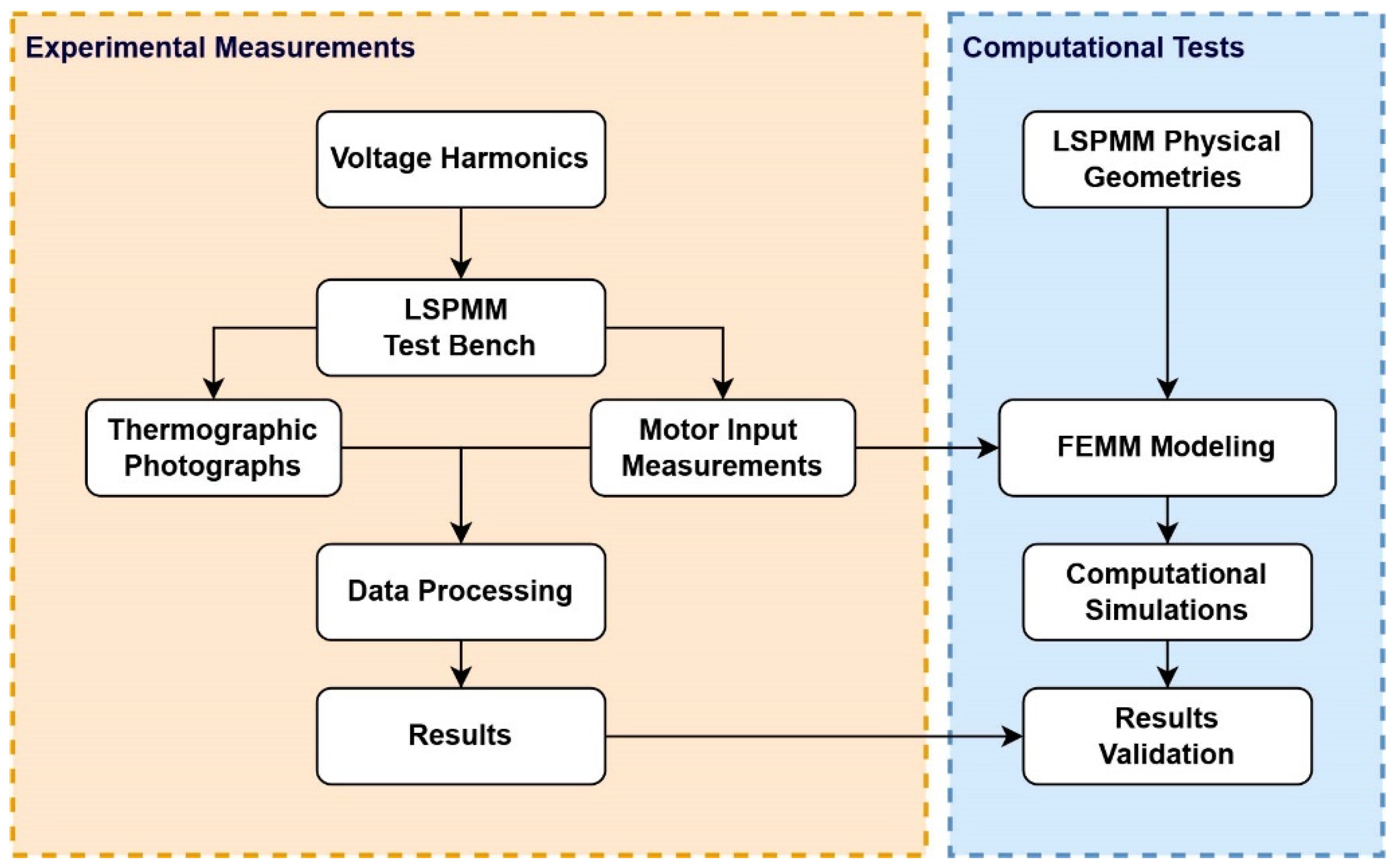
Aiming to validate the model as well as to identify the operational characteristics of the LSPMM, the methodology was separated into two parts: an experimental one and a computational one, as presented in Figure 3. Initially, experimental measurement campaigns were carried out with the LSPMM under ideal conditions until reaching thermal equilibrium according to IEC 60034-2-1 [39], and then, in the presence of voltage harmonics, it increased by 2% every 10 min and then up to 25%. Under these conditions, the motor input parameters as well as thermographic images were recorded for subsequent processing and results.
At the same time, the motor dimensions were modeled in the Finite Elements Method Magnetics (FEMM) software [40] and the materials defined from the motor manufacturer information. After modeling and inserting the voltage harmonics, computational simulations were carried out to verify the performance of this technology in the presence of harmonics, and then, the experimental results were validated.
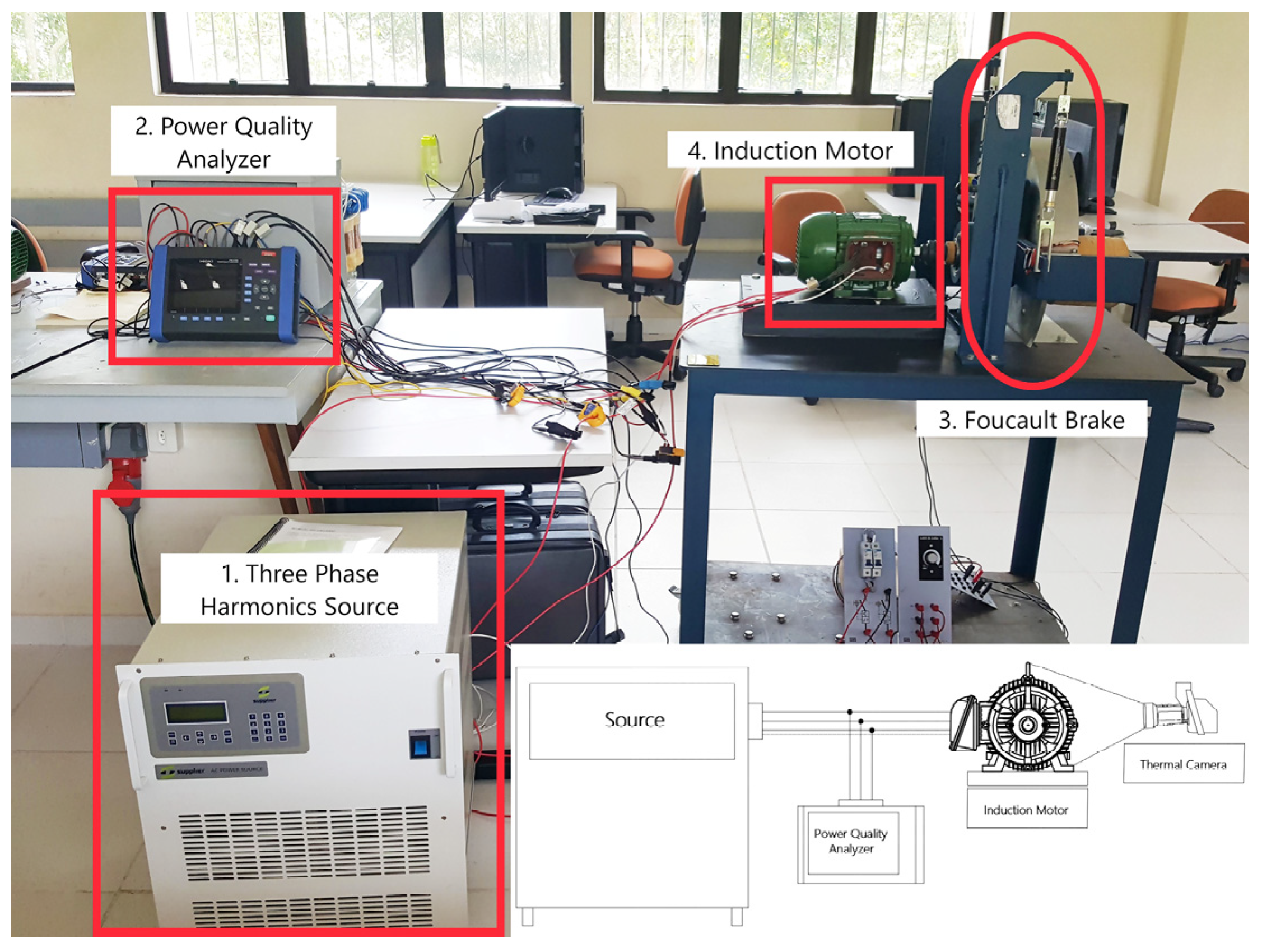
The experimental measurements were carried out using the test bench shown in Figure 4. The test bench is composed of a programmable source (1) in which the harmonics under study were generated. The LSPMM input parameters were measured using a power quality analyzer (2), while the load on the output was controlled by an eddy current brake (3), and finally, the motor data (4) are presented in Table 1. The thermographic measurements were made using a model T620 thermographic camera from the FLIRTM manufacturer with an emissivity of 0.94, which corresponds to the ink of the LSPMM. The images were captured at the two angles presented in Figure 5, every two minutes from thermal equilibrium and then processed in the camera software.
The simulation was performed by considering the strong coupling between the thermal and magnetic effects. The Multiphysics coupling was achieved through FEM, and it was built in the Lua console component, where the calculations were performed interactively over increasing harmonic distortion percentages.
Each iteration is composed of a magnetic simulation and sequentially a thermal simulation; the result of each simulation was used as input to the next, thus achieving strong coupling. At the start of every iteration, the magnetic simulation was realized; Equation (10) was numerically solved to calculate the magnetic vector potential A at all elements that form the analysis region. The resistive losses at the copper strands were also calculated. The next step was the thermal simulation. Equation (19) was numerically solved at all finite elements using the resistive losses calculated in the previous magnetic simulation as heat sources. Electric conductivities were updated to the new temperatures according to (20) and were reinserted into the magnetic simulation of the next time step. This process was repeated iteratively until the simulated timespan was completed, and it is presented in Figure 6.

4. Results

4.1. Experimental Results

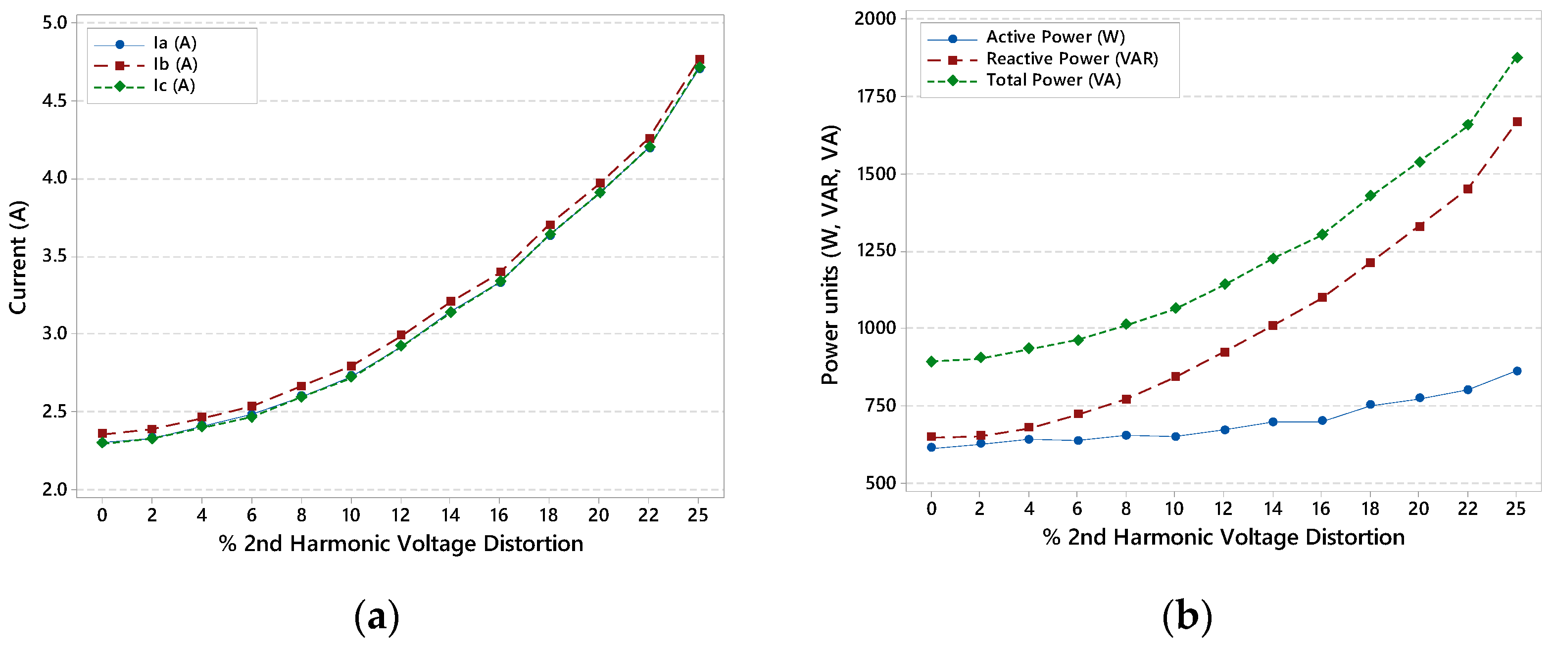
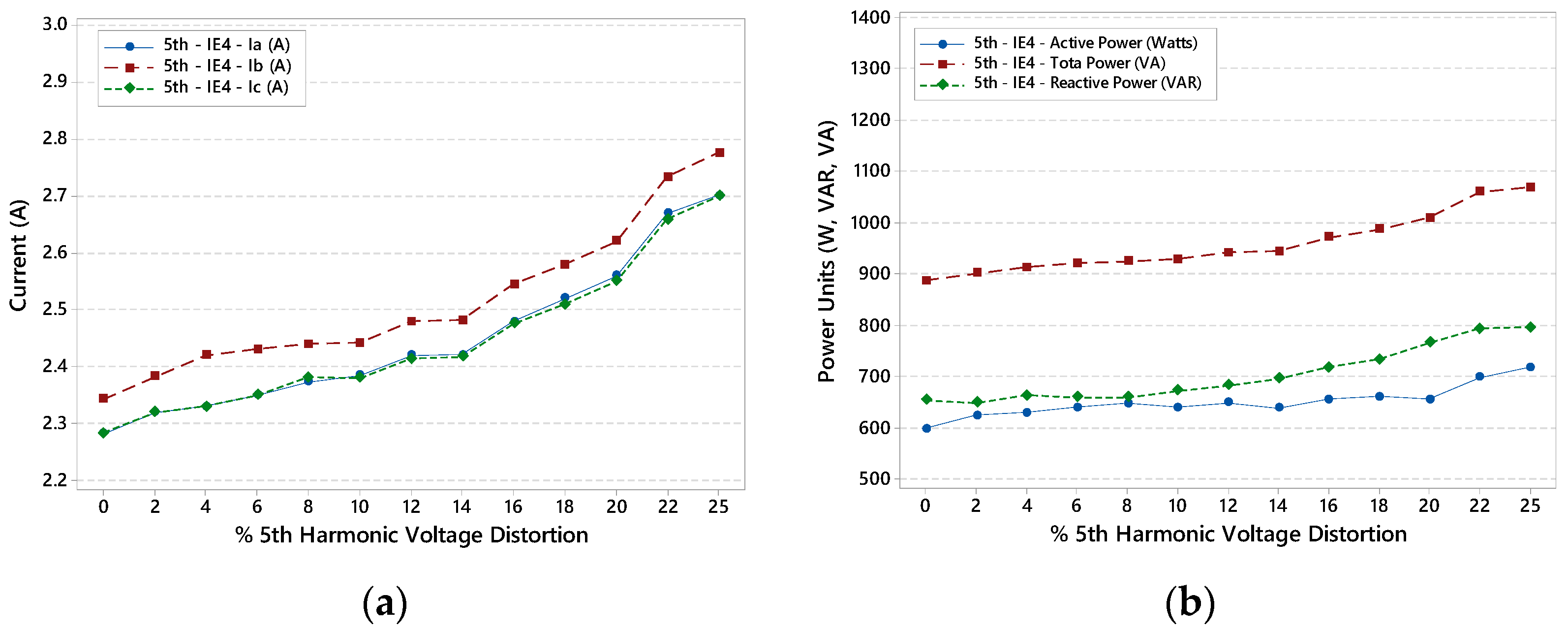
The second- and fifth-order voltage harmonics are classified as negative sequence harmonics and are characterized by generating a magnetic field opposite to the resulting magnetic field in the motor due to the fundamental frequency. This opposite torque produces vibrations and caused a decrease in speed as well as an increase in consumption and motor temperature. In Figure 7 and Figure 8, the input line currents (a) and the active, reactive, and total power (b) are presented for the LSPMM in the presence of 2nd- and 5th-order voltage harmonics.
It can be seen how the total current increases as a result of the negative sequence order voltage harmonics being increased every 10 min, and the same happens for the active, reactive, and total power. However, it is important to clarify that these increases are not due to the rise in the output load of the motor, which maintains a constant load, but due to harmonics since only the fundamental frequency can provide real power at the output [41]. Additionally, this is also verified with the increase in the reactive power of the motor due to the increase in distortion harmonic percentage. In the figures below, it can be observed how the 2nd-order voltage harmonic results in higher increases in the reactive power, mainly due to magnetic losses, as will be presented in Figure 8.
As it was observed in Figure 7 and Figure 8, harmonics result in increases in the LSPMM input power, and this increase translates into losses due to overloads that can reduce the motor’s useful life as well as reduce efficiency and increase consumption, which translate into higher operating costs for users. Figure 9 and Figure 10 present these losses, as observed in the LSPMM thermography images, for the thermal equilibrium condition without the presence of harmonics (thermograms (a) and (c)) and the same angles in the presence of 25% of 2nd- and 5th-order voltage harmonic distortions. The deviation produced by the negative sequence voltage harmonic disturbance is considerable and not recommended since it can degrade the insulation in the motor windings and produce internal short circuits.
In the measurements analysis, it was observed that for this motor, in the presence of only the 2nd- and 5th-order voltage harmonics, new current harmonics appeared, as shown in Figure 11, mainly due to the motor being in the saturation zone. The additional harmonics observed in the analysis for the 2nd-order voltage harmonic are (Figure 11a) 5th-order harmonics of negative sequence as well as 4th- and 7th-order harmonics of positive sequence. These harmonics result in higher oscillations and harmonic losses in the motor, which increase consumption and temperature, two important parameters for the end-user concerning with economic and useful life terms.
For the 5th-order sequence harmonic, a 7th-order harmonic of positive sequence appears, as presented in Figure 11b. This harmonic produces a positive magnetic field that, in combination with the 5th-order magnetic field, results in higher oscillations, vibrations, and noise in the LSPMM for higher harmonic percentages. This fact was considered during the LSPMM modeling in the FEMM software, aiming at a more exact representation of it, as will be presented in the next sections.

4.2. Finite Elements Analysis Results
For the LSPMM modelling and simulation, initially, the problem was defined in the software FEMM with information such as frequency and depth since the software presents a 2D visualization; however, the problem solution is based on the 3D dimension. After defining the problem, the geometry was inserted, created from the physical dimensions of the motor (rotor diameter, number of slots, air gap distance, etc.). For this study, the complete motor was considered to better visualize the paths of flux lines in each harmonic distortion condition. The materials were inserted based on the materials obtained from manufacturer information for the engine analyzed (Figure 12a).
The boundary conditions, which are useful to help direct the motor response in the simulation (magnetic flux response, current response, etc.), were also defined during the motor modelling step, and then the mesh was created and refined until a constant response was obtained (Figure 12b); finally, the simulation was performed, from which the results presented in this section were obtained.
The presence of voltage harmonics results in additional harmonic currents, which induce harmonic voltages in the rotor bars that produce harmonic currents circulating in the rotor squirrel cage. These additional harmonic components produce additional magnetic fields that result in opposite torques, which are translated into a reduction in speed for asynchronous electric motors.
Figure 13 presents the magnetic field lines in the LSPMM in nominal conditions (Figure 13a), 2nd-order voltage harmonic (Figure 13b), and 5th-order voltage harmonic (Figure 13c). It can be seen how the harmonics result in a larger number of flux lines, observed through the magnetic field density, but it is also important to note how the trajectory of the flux lines changes with the presence of harmonics, with special focus on the 2nd-order harmonic flux lines that present longer trajectories, which in turn translates into higher reluctance and consequently higher magnetic losses.
However, the LSPMM speed does not vary for any of the analyzed harmonics, which does not mean that the harmonics do not impact other variables such as consumption, temperature, and power factor.
The objective of using the finite element analysis is to conduct a thorough diagnosis of the motor electromagnetic behavior using a method that is non-invasive and has no interference with the operation of the motor being analyzed. Using this method, it was possible to extract the resistive losses in the stator armature as well as the torque via the weighted stress tensor method [42]. These simulations were performed considering that the motor is operating at no load and with only the fault brakes, which in this case are neglected. To perform the thermal analysis, FEMM solves the problem around the transient temperature model using (19). From that, it is possible to obtain the temperature and gradient values of the temperature model.
In order to account for temperature exchange with the air, we applied the convection boundary condition. Here, we define the thermal transfer coefficient for the inner parts as well as the exterior part of the motor from the parameters used in reference [43] and adjusted based on the motor output power given that the one considered in this study presented a lower power (0.75 kW). For the exterior part of the frame, the coefficient was 30 W/m2 °C. As for the inner parts of the motor, the air gap, and cooling air vents, the coefficient is higher, at 65 W/m2 °C in this case, and the gaps between the stator/rotor armature and coil ends were not considered, as their value is negligible. Figure 14 illustrates the areas where these boundary conditions were applied.
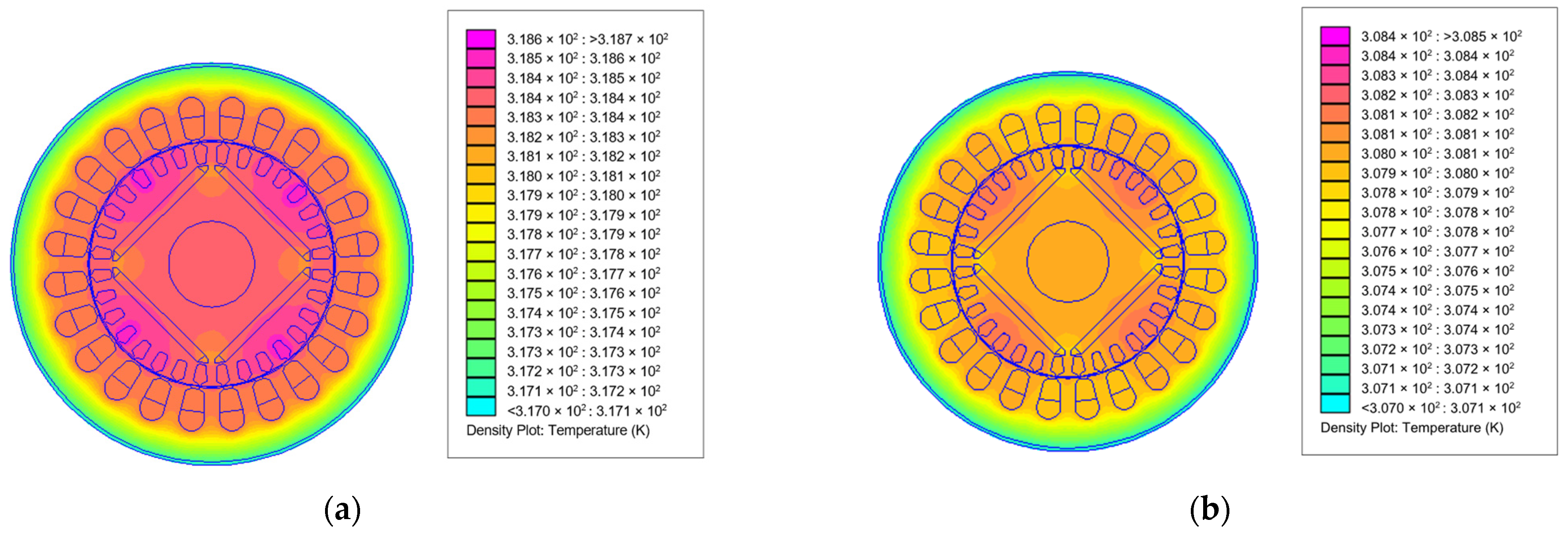
Figure 14. Quarter section of motor illustrating the areas with convection boundary conditions. The temperature distribution in the motor at full load for each voltage harmonic is presented in Figure 15. For the second-order voltage harmonic (Figure 15a), it is observed how the rotor presents the higher temperatures, which, despite the synchronism (zero slip), can be justified by the second-order harmonic component configured at the motor input as well as the new harmonics that appear as a result of the saturation in the ferromagnetic core. Regarding the fifth-order harmonic (Figure 15b), a similar pattern is observed, however, with lower temperatures, which shows that this harmonic is less detrimental to the LSPMM.
Energies 15 08603 g014
Figure 15. Temperature distribution (in Kelvin) in the motor from the FEMM thermal simulation for: (a) second-order voltage harmonic and (b) fifth-order voltage harmonic.
Energies 15 08603 g015
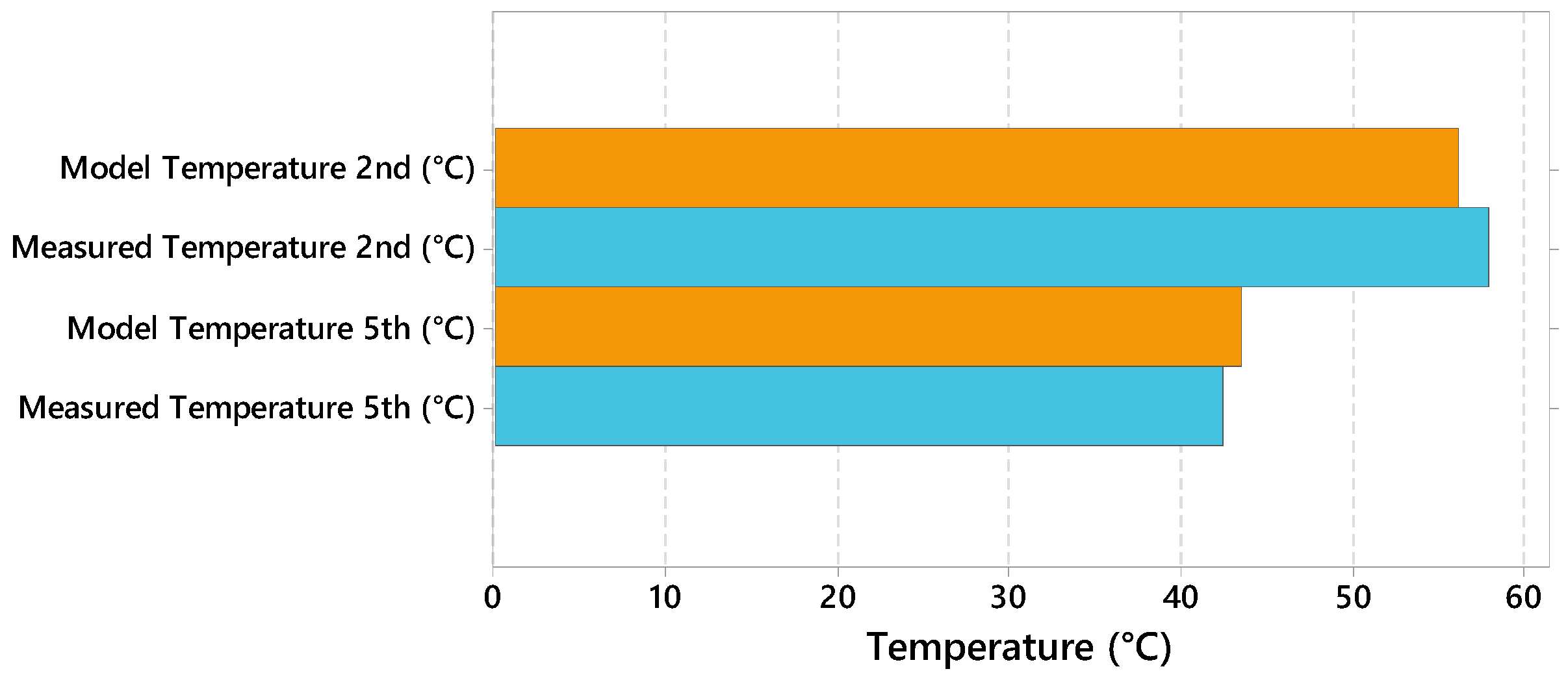
Analogous to the experiment results, the harmonic analysis was carried out for the simulation. Figure 16 shows the LSPMM lateral temperature as simulated in FEMM, with 25% of the voltage harmonic, and its comparison with the experimentally measured temperature in the lateral view of Figure 5a. It should, however, be noted that there is a large discrepancy due to the number of elements in the mesh and also due to not having considered the influence of the permanent magnets-magnetization being affected.
Based on the results obtained from the computational simulation as well as from the experimental measurements, errors of 6.3% and 2.8% for the 2nd- and 5th-order harmonics, respectively, were found, which validates the model proposed on the line-start permanent magnet motor in this work.

5. Conclusions

The present study aimed to analyze the line-start permanent magnet motor experimentally and through computational simulations using FEMM in the presence of second- and fifth-order voltage harmonics. With this objective, measurement campaigns were carried out on a 0.75 kW permanent magnet motor and simulations based on the physical dimensions and construction characteristics of the machine.
From the experimental results, it was possible to observe the considerable impact that the 2nd- and 5th-order harmonics of the negative sequence have on the LSPMM. Concerning currents, increases were observed mainly due to the reactive power increases as a product of the high harmonic frequencies in the leakage reactance and the magnetization branch reactance, while the active power presents small increments, which will result in lower power factors for each harmonic and higher temperatures. This impact can be justified in the construction of more efficient motors, in which the magnetization and leakage reactance present lower values, which will decrease losses but also reduce the filtering of external harmonics in the motor. The computational simulation, on the other hand, showed that the created model reliably represents the performance of the motor in non-ideal conditions, such as in the presence of the negative sequence voltage harmonic, showing its considerable effect on the internal thermal distribution of the motor.
The simulations in the FEMM software also allowed a better evaluation of the magnetic losses in the presence of voltage harmonics. From the magnetic flux paths changes in the presence of harmonics that produce additional temperatures in the motor, observed in the experimental measures and validated from the model built based on the motor geometry, and that can be certainly useful to determine the main effects of these disturbances on components such as motor bearings or insulation degradation, aiming to program predictive maintenance with adequate frequencies to the disturbances present in the motor.
The creation and validation of the LSPMM model allow evaluating the state of the motors from the experimental data using numerical methods that will certainly give a clearer scenario of the thermal-magnetic behavior of the motor, which can be easily extended to a predictive maintenance product with wide application in the industry and in electric mobility in general.

Author Contributions

Conceptualization, J.M.T. and W.d.S.F.; methodology, J.M.T. and W.d.S.F.; software, W.d.S.F. and B.K.T.; validation, J.M.T., W.d.S.F. and B.K.T.; formal analysis, J.M.T. and W.d.S.F.; investigation, J.M.T. and W.d.S.F.; resources, W.d.S.F.; data curation, J.M.T. and B.K.T.; writing—original draft preparation, J.M.T., W.d.S.F. and B.K.T.; writing—review and editing, U.H.B., M.E.d.L.T., E.O.d.M. and W.d.S.F.; supervision, U.H.B., M.E.d.L.T., E.O.d.M., M.d.O.e.S. and W.d.S.F.; funding acquisition, W.d.S.F. and M.d.O.e.S. All authors have read and agreed to the published version of the manuscript.

Funding

This research was funded by the National Academic Cooperation Program in the Amazon (PROCAD), Process No. 88887.200548/2018-00.

Institutional Review Board Statement

Not applicable.

Informed Consent Statement

Not applicable.

Data Availability Statement

Not applicable.

Acknowledgments

This work was supported by the Brazilian National Council of Scientific and Technological Research (CNPq) as well as the Paulo Freire + Program.

Conflicts of Interest

The authors declare no conflict of interest.

References

  1. Sarac, V.J.; Stefanov, G. Various Rotor Topologies of Line-Start Synchronous Motor for Efficiency Improvement. Power Electron. Drives 2019, 5, 83–95. [Google Scholar] [CrossRef]
  2. Zeng, X.; Quan, L.; Zhu, X.; Xu, L.; Liu, F. Investigation of an Asymmetrical Rotor Hybrid Permanent Magnet Motor for Approaching Maximum Output Torque. IEEE Trans. Appl. Supercond. 2019, 29, 1–4. [Google Scholar] [CrossRef]
  3. Study on Line-Start Permanent Magnet Assistance Synchronous Reluctance Motor for Improving Efficiency and Power Factor. Available online: https://www.mdpi.com/1996-1073/13/2/384 (accessed on 16 March 2022).
  4. Zöhra, B.; Akar, M. Design Trends for Line Start Permanent Magnet Synchronous Motors. In Proceedings of the 2019 3rd International Symposium on Multidisciplinary Studies and Innovative Technologies (ISMSIT), Ankara, Turkey, 11–13 October 2019; pp. 1–7. [Google Scholar]
  5. Lyskawinski, W. Comparative Analysis of Energy Performance of Squirrel Cage Induction Motor, Line-Start Synchronous Reluctance and Permanent Magnet Motors Employing the Same Stator Design. Arch. Electr. Eng. 2020, 69, 967–981. [Google Scholar] [CrossRef]
  6. Ferreira, F.J.T.E.; Leprettre, B.; de Almeida, A.T. Comparison of Protection Requirements in IE2-, IE3-, and IE4-Class Motors. IEEE Trans. Ind. Appl. 2016, 52, 3603–3610. [Google Scholar] [CrossRef]
  7. Tshoombe, B.K.; Muñoz Tabora, J.; da Silva Fonseca, W.; Emília Lima Tostes, M.; de Matos, E.O. Voltage Harmonic Impacts on Line Start Permanent Magnet Motor. In Proceedings of the 2021 14th IEEE International Conference on Industry Applications (INDUSCON), São Paulo, Brazil, 16–18 August 2021; pp. 962–968. [Google Scholar]
  8. Muñoz Tabora, J.; de Lima Tostes, M.E.; Ortiz de Matos, E.; Mota Soares, T.; Bezerra, U.H. Voltage Harmonic Impacts on Electric Motors: A Comparison between IE2, IE3 and IE4 Induction Motor Classes. Energies 2020, 13, 3333. [Google Scholar] [CrossRef]
  9. Influence of Voltage Subharmonics on Line Start Permanent Magnet Synchronous Motor. Available online: https://ieeexplore.ieee.org/document/9641816 (accessed on 16 March 2022).
  10. Debruyne, C.; Sergeant, P.; Derammelaere, S.; Desmet, J.J.M.; Vandevelde, L. Influence of Supply Voltage Distortion on the Energy Efficiency of Line-Start Permanent-Magnet Motors. IEEE Trans. Ind. Appl. 2014, 50, 1034–1043. [Google Scholar] [CrossRef]
  11. Debruyne, C. Impact of Voltage Distortion on Energy Efficiency of Induction Machines and Line Start Permanent Magnet Machines; Ghent University: Ghent, Belgium, 2014. [Google Scholar]
  12. Tabora, J.M.; De Lima Tostes, M.E.; De Matos, E.O.; Bezerra, U.H.; Soares, T.M.; De Albuquerque, B.S. Assessing Voltage Unbalance Conditions in IE2, IE3 and IE4 Classes Induction Motors. IEEE Access 2020, 8, 186725–186739. [Google Scholar] [CrossRef]
  13. Tabora, J.M.; De Lima Tostes, M.E.; Bezerra, U.H.; De Matos, E.O.; Filho, C.L.P.; Soares, T.M.; Rodrigues, C.E.M. Assessing Energy Efficiency and Power Quality Impacts Due to High-Efficiency Motors Operating Under Nonideal Energy Supply. IEEE Access 2021, 9, 121871–121882. [Google Scholar] [CrossRef]
  14. López-Pérez, D.; Antonino-Daviu, J. Application of Infrared Thermography to Failure Detection in Industrial Induction Motors: Case Stories. IEEE Trans. Ind. Appl. 2017, 53, 1901–1908. [Google Scholar] [CrossRef]
  15. Diagnosis of the Three-Phase Induction Motor Using Thermal Imaging-ScienceDirect. Available online: https://www.sciencedirect.com/science/article/abs/pii/S1350449516306259 (accessed on 16 March 2022).
  16. Ferreira, F.J.T.E.; de Almeida, A.T.; Carvalho, J.F.S.; Cistelecan, M.V. Experiments to Observe the Impact of Power Quality and Voltage-Source Inverters on the Temperature of Three-Phase Cage Induction Motors Using an Infra-Red Camera. In Proceedings of the 2009 IEEE International Electric Machines and Drives Conference, Miami, FL, USA, 3–6 May 2009; pp. 1311–1318. [Google Scholar]
  17. Singh, G.; Anil Kumar, T.C.; Naikan, V.N.A. Fault Diagnosis of Induction Motor Cooling System Using Infrared Thermography. In Proceedings of the 2016 IEEE 6th International Conference on Power Systems (ICPS), New Delhi, India, 4–6 March 2016; pp. 1–4. [Google Scholar]
  18. Mahami, A.; Rahmoune, C.; Bettahar, T.; Benazzouz, D. Induction Motor Condition Monitoring Using Infrared Thermography Imaging and Ensemble Learning Techniques. Adv. Mech. Eng. 2021, 13, 16878140211060956. [Google Scholar] [CrossRef]
  19. Azari, M.N.; Mirsalim, M. Performance Analysis of a Line-Start Permanent Magnet Motor with Slots on Solid Rotor Using Finite-Element Method. Electr. Power Compon. Syst. 2013, 41, 1159–1172. [Google Scholar] [CrossRef]
  20. Fonseca, D.; Santos, C.C.; Cardoso, A. Modelling of a Line-Start Permanent Magnet Synchronous Motor, Using Empirical Parameters. In Proceedings of the International Conference on Engineering ICEUBI2017, Covilhã, Portugal, 5–7 December 2017. [Google Scholar]
  21. Robust Design Optimization of a Five-Phase PM Hub Motor for Fault-Tolerant Operation Based on Taguchi Method. Available online: https://ieeexplore.ieee.org/document/9076301 (accessed on 10 October 2022).
  22. Sun, X.; Xu, N.; Yao, M. Sequential Subspace Optimization Design of a Dual Three-Phase Permanent Magnet Synchronous Hub Motor Based on NSGA III. IEEE Trans. Transp. Electrif. 2022, 1. Available online: https://ieeexplore.ieee.org/document/9828489 (accessed on 13 July 2022). [CrossRef]
  23. Xu, J.; Zhang, L.; Meng, D.; Su, H. Simulation, Verification and Optimization Design of Electromagnetic Vibration and Noise of Permanent Magnet Synchronous Motor for Vehicle. Energies 2022, 15, 5808. [Google Scholar] [CrossRef]
  24. Liu, X.; Lin, Q.; Fu, W. Optimal Design of Permanent Magnet Arrangement in Synchronous Motors. Energies 2017, 10, 1700. [Google Scholar] [CrossRef] [Green Version]
  25. Yeo, H.-K.; Ro, J.-S. Novel Analytical Method for Overhang Effects in Surface-Mounted Permanent-Magnet Machines. IEEE Access 2019, 7, 148453–148461. [Google Scholar] [CrossRef]
  26. Li, J.; Song, J.; Cho, Y. High Performance Line Start Permanent Magnet Synchronous Motor for Pumping System. In Proceedings of the 2010 IEEE International Symposium on Industrial Electronics, Bari, Italy, 4–7 July 2010; pp. 1308–1313. [Google Scholar]
  27. Cavagnino, A.; Vaschetto, S.; Ferraris, L.; Gmyrek, Z.; Agamloh, E.B.; Bramerdorfer, G. Striving for the Highest Efficiency Class With Minimal Impact for Induction Motor Manufacturers. IEEE Trans. Ind. Appl. 2020, 56, 194–204. [Google Scholar] [CrossRef]
  28. Influence of Magnetic Slot Wedge on the Performance of 10-kV, 1000-kW Permanent Magnet Synchronous Motor-Qiu-2020-International Transactions on Electrical Energy Systems-Wiley Online Library. Available online: https://onlinelibrary.wiley.com/doi/abs/10.1002/2050-7038.12332 (accessed on 16 March 2022).
  29. Frosini, L.; Pastura, M. Analysis and Design of Innovative Magnetic Wedges for High Efficiency Permanent Magnet Synchronous Machines. Energies 2020, 13, 255. [Google Scholar] [CrossRef] [Green Version]
  30. IEC 60034-30-1:2014|IEC Webstore|Pump, Motor, Water Management, Smart City, Energy Efficiency. Available online: https://webstore.iec.ch/publication/136 (accessed on 10 June 2022).
  31. Fong, J.; Ferreira, F.J.T.E.; Silva, A.M.; de Almeida, A.T. IEC61800-9 System Standards as a Tool to Boost the Efficiency of Electric Motor Driven Systems Worldwide. Inventions 2020, 5, 20. [Google Scholar] [CrossRef]
  32. Electric Motors. Available online: https://ec.europa.eu/info/energy-climate-change-environment/standards-tools-and-labels/products-labelling-rules-and-requirements/energy-label-and-ecodesign/energy-efficient-products/electric-motors_en (accessed on 12 May 2021).
  33. Ferreira, F.J.T.E.; Silva, A.M.; Aguiar, V.P.B.; Pontes, R.S.T.; Quispe, E.C.; de Almeida, A.T. Overview of Retrofitting Options in Induction Motors to Improve Their Efficiency and Reliability. In Proceedings of the 2018 IEEE International Conference on Environment and Electrical Engineering and 2018 IEEE Industrial and Commercial Power Systems Europe (EEEIC/I CPS Europe), Palermo, Italy, 12–15 June 2018; pp. 1–12. [Google Scholar]
  34. European Committee of Manufacturers of Electrical Machines and Power Electronics (CEMEP). Ecodesign Regulations (EU) 2019/1781 for Motor and Drives and (EU) 2021/341 (Amendment) from CAPIEL and CEMEP. 10 May 2021. Available online: https://www.nord.com/cms/en/product_catalogue/ie2_motors/country_regulations/cp_countryregulations.jsp (accessed on 2 August 2020).
  35. WEG. Energy Efficiency Primer. Available online: http://Materiais.Motores.Weg.Net/Cartilha (accessed on 27 July 2022).
  36. Hughes, A.; Drury, B. Electric Motors and Drives, 4th ed.; Elsevier Ltd.: Leeds, UK, 2013; ISBN 978-0-08-098332-5. [Google Scholar]
  37. Meeker, D. Finite Element Method Magnetics; User’s Manual; Version 4.2. Available online: http://www.femm.info/Archives/doc/manual34.pdf (accessed on 1 October 2022).
  38. A Thermal Analysis of Induction Motors Using a Weak Coupled Modeling. Available online: https://ieeexplore.ieee.org/document/582603 (accessed on 18 October 2022).
  39. IEC 60034-2-1:2014|IEC Webstore|Energy Efficiency, Smart City. Available online: https://webstore.iec.ch/publication/121 (accessed on 27 July 2022).
  40. HomePage: Finite Element Method Magnetics. Available online: https://www.femm.info/wiki/HomePage (accessed on 27 July 2022).
  41. Kumar, L.A.; Alexander, S.A. Computational Paradigm Techniques for Enhancing Electric Power Quality; CRC Press: Boca Raton, FL, USA, 2018; ISBN 978-0-429-80990-3. [Google Scholar]
  42. Saha, S.; Cho, Y.H. Starting Characteristic Analysis of LSPM for Pumping System Considering Demagnetization. Int. J. Mech. Mechatron. Eng. 2015, 9, 1305–1311. [Google Scholar]
  43. Palangar, M.F. Design, Analysis and Optimization of Line-Start Permanent-Magnet Synchronous Motors: Simultaneous Electromagnetic and Thermal Analysis. Available online: https://theses.flinders.edu.au/view/8616886a-3b6f-4c97-a9d0-95452aa86a65/1 (accessed on 1 November 2022).
Figure 1. Countries with MEPS for electric motors [33,34].
Energies 15 08603 g001
Figure 2. Line-start permanent magnet motor magnetic fields [7]: (a) stator winding fields; (b) permanent magnets fields; (c) stator and rotor magnetic fields.
Energies 15 08603 g002
Figure 3. Methodology Flowchart.
Energies 15 08603 g003
Figure 4. General test setup [8].
Energies 15 08603 g004
Figure 5. Thermographic images of the line-start permanent magnet motor in presence of voltage harmonics [8]: (a) lateral view; (b) front view.
Energies 15 08603 g005
Figure 6. Flowchart for numerical simulations with strong thermo-magnetic coupling.
Energies 15 08603 g006
Figure 7. LSPMM in the presence of second voltage harmonic: (a) input line currents; (b) active, reactive, and total Power.
Energies 15 08603 g007
Figure 8. LSPMM in the presence of fifth voltage harmonic: (a) input line currents; (b) active, reactive and total Power.
Energies 15 08603 g008
Figure 9. Thermographic images of the line-start permanent magnet motor in presence of 2nd-order voltage harmonics in frontal and lateral view: (a) thermal equilibrium frontal view; (b) 25% of 2nd-order voltage harmonic in frontal view; (c) thermal equilibrium lateral view; (d) 25% of 2nd-order voltage harmonic in lateral view.
Energies 15 08603 g009
Figure 10. Thermographic images of the line-start permanent magnet motor in presence of 5th-order voltage harmonics in frontal and lateral view: (a) thermal equilibrium frontal view; (b) 25% of 5th-order voltage harmonic in frontal view; (c) thermal equilibrium lateral view; (d) 25% of 5th-order voltage harmonic in lateral view.
Energies 15 08603 g010
Figure 11. Harmonic currents present in LSPMM in the presence of (a) 2nd-order voltage harmonic and (b) 5th-order voltage harmonic [13].
Energies 15 08603 g011
Figure 12. Line-start permanent magnet motor simulation on FEMM: (a) LSPMM geometry and materials and (b) LSPMM mesh.
Energies 15 08603 g012
Figure 13. Density flux plot for (a) nominal conditions; (b) 2nd-order voltage harmonics and (c) 5th-order voltage harmonics.
Energies 15 08603 g013
Figure 16. Comparison between the model and measured temperature for 25% voltage harmonic distortion of 2nd- and 5th-order harmonics.
Energies 15 08603 g016
Table 1. Line-start Permanent Magnet Motor Parameters.
Induction Motor ClassIE4 Class
TechnologyLSPMM
Power0.75 kW
Voltage220 V/380 V
Speed (rpm)1800
Torque (Nm)3.96
Current (A)3.08/1.78
Efficiency (%)87.4
Power Factor0.73
Publisher’s Note: MDPI stays neutral with regard to jurisdictional claims in published maps and institutional affiliations.