Review

Thermal Energy Storage in Concentrating Solar Power Plants: A Review of European and North American R&D Projects

Departamento de Ingeniería Mecánica, Escuela de Ingeniería y Arquitectura (EINA), Universidad de Zaragoza, C/María de Luna s/n, 50018 Zaragoza, Spain
*
Author to whom correspondence should be addressed.
Energies 2022, 15(22), 8570; https://doi.org/10.3390/en15228570
Submission received: 3 August 2022 / Revised: 4 November 2022 / Accepted: 9 November 2022 / Published: 16 November 2022
(This article belongs to the Section A: Sustainable Energy)

Abstract

:
Thermal energy storage (TES) is the most suitable solution found to improve the concentrating solar power (CSP) plant’s dispatchability. Molten salts used as sensible heat storage (SHS) are the most widespread TES medium. However, novel and promising TES materials can be implemented into CSP plants within different configurations, minimizing the TES costs and increasing the working temperature to improve the thermal performance of the associated power block. The first objective of this review is to provide an overview of the most widespread CSP technologies, TES technologies and TES-CSP configurations within the currently operational facilities. Once this information has been compiled, the second aim is to collect and present the existing European and North American TES-CSP Research and Development (R&D) projects within the last decade (2011–2021). Data related to these projects such as TES-CSP configuration path, TES and CSP technologies applied, storage capacity, power block associated and the levelized cost of electricity (LCOE) of the commercial up-scaling project are presented. In addition, project information such as location, research period, project leader and budget granted are also extracted. A timeline of the R&D projects launched from 2011 is built, showing the technology readiness level (TRL) achieved by the end of the project.

1. Introduction

One of the most important measures to mitigate greenhouse gases (GHG) emissions is to increase the share of renewable energy sources (RES) in the energy mix, according to the Intergovernmental Panel on Climate Change (IPCC) [1]. At the end of 2021, the renewable energy share in global electricity production was 28.3% with a renewable power capacity exceeding 3000 GW, including hydroelectric power. The annual contribution to renewable power capacity must be multiplied by three to achieve the scenarios of net zero emissions by 2030 and 2050 [2]. Higher daily production of RES could be achieved if those issues related to the variability of electricity production were solved through the storage of energy surplus.
RES which directly supplies electricity to the grid, such as photovoltaic solar power or wind power, may be combined with electromechanical or electrochemical storage systems leading to efficiencies of the load/discharge cycle up to 90% [3]. In contrast, concentrating solar power (CSP) plants which supplies thermal energy to the power cycle, obtain yields close to 100% through their combination with thermal energy storage (TES) systems [3,4]. Furthermore, the capital cost of TES is lower than mechanical or chemical storage systems [5]. The most widespread storage materials used in TES systems are the molten salts which allow for the extension of the operating hours of CSP plants by storing energy as sensible heat during daylight hours. However, thermochemical energy storage (TCES) systems could enable higher conversion efficiencies in CSP plants in the medium–long term [6]. Although the CSP installed capacity in 2021 (6 GW) was significantly lower than the installed capacity of other RES, the average CSP costs in plants with integrated TES have dropped by 70% in the last decade [2]. The construction of CSP plants in the last decade has grown exponentially throughout the world, indicating an optimistic future for the solar-based RES [7]. Therefore, CSP with TES is emerging as a potential competitor of conventional base load plants, such as fossil fuel power plants [8]. The latest research highlights the importance of techno–economic studies to promote the implementation of TES in CSP. However, the environmental aspect scarcely appears in the literature, even less complete life cycle assessments [9]. Thus, the first objective of this review is to describe the most advantageous integration pathways of TES into CSP plants.
A thorough bibliographic search points out that recent reviews dealing with energy storage technologies coupled with CSP plants may be divided into two categories: (i) latest advances in CSP and TES technologies and (ii) integration concepts. Several studies focus on the most widespread CSP technologies and the future trends in research development [10,11,12,13], including an overview of the distribution of CSP facilities by regions [7]. Regarding TES technologies, the reviews were focused on sensible, latent and thermochemical energy storage materials developed since 2000 [14] and the future challenges to be integrated into CSP [15]. The latest research on sensible heat storage was related to (i) the discussion of the best integration of molten salts medium [5], (ii) the potential of solid particles as a heat transfer medium and TES [16] and (iii) the proper future use of cheaper materials such as rocks [17]. The latent heat storage for high temperature operation was investigated to, firstly, overcome challenges of coupling to CSP [18] and to define the phase change materials capable to be used in CSP application [19]. The recent advances on thermochemical reactions as TES for CSP are the most investigated in the last 5 years, given the high operating temperature and long-term durability of solid–gas reversible reactions [20]. Most recent reviews were focused on the most suitable reactors for enhancing heat transfer [21] and chemical reactions efficiency [22]. Secondly, the integration between TES and CSP was defined according to the conventional configurations of first and second generation CSP plants [11,23], requiring new integration concepts for the next generation of CSP plants [24]. In summary, previous reviews focused on TES CSP configurations of currently operational facilities from prototype to commercial scale (first and second generation) and novel trends for TES integration in the next CSP generation. The main gap found among these reviews is the existence of a thorough summary of completed and ongoing research and development (R&D) projects of TES integrated in CSP plants. Thus, the second objective and the main novelty of this revision manuscript is to present a complete international picture of the TES CSP R&D projects from Europe and North America within any technology readiness level (TRL), from lab/pilot to almost commercial scale. Both regions concentrate 65% of the installed capacity of CSP plants currently in operation [25]. Thus, Europe and North America have been the world regions chosen for the review of R&D projects for being at the forefront in the development of CSP technology.
A bibliometric study was performed to search the references for the following sections in the present manuscript (Section 2 and Section 3). The Web of Science database was selected for citations belonging to Section 2, focused on CSP and TES technologies, as well as the most spread integrations of TES into CSP plants. In addition, the SolarPACES tool [25] was required to obtain the project profiles of operational CSP facilities around the world. The information about R&D projects in Section 3 was extracted from other databases, such as the Community Research and Development Information Service (CORDIS) [26] and Solar Energy Research Database from the Solar Energy Technologies Office (SETO) [27]. CORDIS provides results from R&D projects funded by the EU’s framework programmes, while SETO collects all the active and inactive R&D projects awarded by the U.S. Department of Energy. Table 1 shows the different keyword combinations used to select the scientific references appearing in the present review.
The keywords shown in Table 1 were used to collect the citations related to CSP and TES. The excluded phrase for all searches performed is ‘photovoltaic’ and the main phrase ‘concentrated solar power’ is the base word used for all searches. Both main and complementary phrases were searched for as topics in the Web of Science database. The total scientific papers found by each row search are also presented in Table 1. Most of the publications are found by more than one search row, being the sum of all articles higher than the total papers. Moreover, cross references are removed from the present review. At least 88 scientific articles within total papers found have been used to describe the CSP and TES review information, of which 41 were published in the last 5 years from 2018 to 2022.
Table 2 shows the total number of CSP facilities and TES CSP R&D projects found under a proposed keyword map for each research tool: SolarPACES, CORDIS and SETO.
The operational CSP plants described in the present review were extracted from the SolarPACES database tool. Most of the information appearing in the profile of each CSP facility has been used throughout this manuscript. Some of the found TES CSP R&D projects: (i) contain duplicate information, or (ii) are out of scope, being related to topics such as photovoltaics or building air-conditioning. Thus, a total of 41 TES CSP R&D projects have been collected from CORDIS and SETO research tools for the present review.

2. Potential Integration of TES in CSP Plants

The typical configuration of an integrated TES CSP plant is illustrated in Figure 1, including the three main blocks of these systems: (i) solar field, (ii) power cycle and (iii) transport media/storage system [28]. This section provides a brief description of the solar collectors and thermal energy storage available technologies and a critical discussion of pros and cons of these technologies and their potential combinations.
Current operation of CSP plants is analogous to conventional thermal power plants, except for the use of solar radiation as a thermal energy source to produce electrical energy through an associated power cycle. A working fluid transfers the thermal energy, circulating between the solar field and the power block. The solar field is composed of concentrators, to improve the use of solar radiation, which is concentrated and projected onto a receiver to heat up at high temperature the working fluid [29]. The typical power block associated with a CSP plant is the steam Rankine cycle. Most of the existing operational CSP plants use a steam turbine for power generation [25]. However, the trend in recent research is to couple CSP with CO2-based power cycles: Brayton [30,31] and supercritical (sCO2) [32], improving the overall efficiency of the CSP plant. Besides, the integration of TES in CSP plants will improve their dispatchability when solar radiation is only partially available or during the night [10]. More than half of the total CSP plants which are currently under operation around the world integrate TES systems. Commercial plants represent around 80% of the currently ongoing CSP facilities with TES. The rest of TES CSP facilities are divided among demonstration plants (13%), pilot plants (6%) and prototypes (1%) [9]. Both, the first and second generation of CSP plants have contributed to the development of current commercial CSP facilities, contemplating (i) the direct steam production in the receiver and (ii) higher volumes of molten salt-based storage. The next (third) generation of CSP plants will focus on the research of (i) new non-corrosive TES materials with high heat absorption and high operational durability, (ii) new HTFs with high-temperature and high-degradability resistance and (iii) more efficient power blocks, such as Brayton and supercritical [33].

2.1. CSP Technologies

Table 3 shows the main characteristics of the most widespread concentrating solar technologies in CSP plants classified as: (i) parabolic trough collectors (PTC), (ii) linear Fresnel reflectors (LFR), (iii) solar power towers (SPT) and (iv) parabolic dish collectors (PDC), where PTC is the largest developed and established globally [10,24].
PTC and LFR concentrating technologies focus the solar radiation on a linear receiver, while PDC and SPT concentrating solar systems direct solar radiation to a focal point where the receiver is located [11]. The highest solar concentration ratio (up to 3000) is achieved by PDC and SPT [11], reaching high (i) operating temperatures (even above 1000 °C) [24], (ii) thermodynamic efficiencies for the CSP plant [34] and (iii) nominal power capacities (up to 280 and 377 MW, respectively) [9]. The most widespread concentrating solar technology is PTC (62%) followed by SPT (20%) and LFR (7%), within 141 CSP plants currently in operation and under construction. Meanwhile, CSP plants with concentrated solar power PDC technology are currently inoperative [25]. Thus, the development status of PTC and SPT is commercially available, both growing at the same rate in new construction facilities improving their performance, the TES and HTF media [13].
The high thermal efficiency of PDC and SPT, near 30%, and its high-temperature operation makes these emerging technologies very competitive with conventional PTC (18%, 400 °C) and LFR (12%, below 400 °C) applications. However, current TRL of these CSP technologies points out the commercial status of PTC and LFR, while wider experimental feedback, especially at large scale, is required to better know and define the disadvantages of the most efficient technologies. Given their tested characteristics, PTC presents a strong potential to become the leading CSP technology in the mid-term.
The cost assessment of these technologies shows the highest average specific costs associated to PTC, although other technologies such as LFR or SPT with slightly lower specific costs present values of the same order of magnitude. The higher thermal efficiency of SPT mitigate the investment costs leading to the lowest average levelized cost of electricity (LCOE) among CSP technologies. The average specific cost and the LCOE of the CSP plants with SPT technology is 18% and 40% lower than CSP plants with PTC technology, respectively. The efficiency of PTC is not high enough to reverse the effect of the largest average investment costs and leads to the highest LCOE.
All the CSP plants which are currently under construction contemplate the use of TES instead of the possibility of increasing electricity production with fossil fuels [25]. This trend is driven by the reduction of annual operation and maintenance costs of TES compared to a fossil fuel support system. Moreover, the capacity factor is improved by increasing the electricity production and GHG emissions are minimized. The variability of the TES material annual costs from one year to the next is lower than fossil fuels, whose price trend is less predictable [35].

2.2. TES Technologies/Systems

Regarding the maturity (TRL level, Table 4), the most developed storage technology relies on sensible heat storage (SHS), followed by latent heat storage (LHS) and finally thermochemical energy storage (TCES).
Information on large experimental and industrial-scale plants is available for SHS operation. SHS is based on liquid or solid storage media, liquid medium being the most commonly used in CPS plants, such as water or molten salts [23,25]. LHS technology is still under development for later integration into CPS plants, being mainly at experimental and pilot scale. Although the TRL of LHS systems is somehow lower, LHS are also commercially available for some specific materials [36]. However, TCES is not currently available at commercial scale. Most of the TCES systems are still investigated at laboratory scale for their integration in CSP plants [37].
The energy density of the LHS media is higher than of SHS media, given the higher enthalpy related to the phase change [23]. However, TCES system has the highest energy density compared to other TES [37]. Several TCES materials are currently under development but not commercially available, while SHS materials are widely commercially available. The heat transfer mechanisms are slow for both LHS and TCES, since their materials present low thermal conductivities [24].
The lifetime of SHS materials (which can reach 20 years) is four times higher than that of LHS materials and even ten times higher than TCES materials [38]. The storage time of TCES materials exceeds that of LHS and SHS materials, even reaching a temporary scale of years.
Based on the information gathered in Table 4, strong R&D efforts in the development of TCES (TRL 4–7) must be conducted to overcome those drawbacks identified for this technology, since its potential to gain the leadership among TES-CSP technologies is extremely high. The accumulation of key advantages when compared to SHS and LHS technologies, such as the higher energy density, the smaller required volumes or the dramatic increase of the storage period without significant energy losses, makes TCES the most promising technology to couple with CSP plants in the long-term. However, efforts must be carried out to find materials with a long lifetime (avoiding melting/sintering issues, achieving complete reversibility, enhancing reaction kinetics) able to be in stored at low temperature. The improvement of heat and mass transfer mechanisms, together with the simplification of TCES operation, will also lead to a needed reduction of capital costs to become economically competitive.
TES systems can be classified by the materials and technology used, such as storage medium [39,40]. Figure 2 shows the main storage materials used by each TES technology: SHS, LHS and TCES.

2.2.1. Sensible Heat Storage (SHS)

Sensible heat storage (SHS) is the simplest method, based on the storage of thermal energy by raising the temperature of a liquid or solid storage medium (e.g., water, sand, molten salts, or rocks), without undergoing phase change over the temperature range of the storage process. SHS systems are cheap, commercial, simple and easy to control, but they present low energy density compared with LHS systems [37].
SHS systems use the heat capacity and the temperature variation of the storage medium during the process of charging and discharging. The amount of heat stored depends on (i) the specific heat of the medium, (ii) the temperature variation and (iii) the amount of storage material option [41,42] (Equation (1)).
Q s = T i T f m · c p   dT   m · c p · T f     T i
where Qs is the quantity of heat stored (J), m is the mass of heat storage medium (kg), cp is the specific heat (J/(kg·K)), Ti is the initial temperature (°C) and Tf is the final temperature (°C).
The most popular SHS materials withstand high temperatures (>500 °C), such as concrete, ceramics, graphite, rocks or sands [24,43]. Storage temperatures up to 1000 °C are mainly standby regenerator-type storage systems which transfer heat from gas directly to the solid material. Ceramics and concrete materials are being used in CSP operational facilities in demonstration, such as in the Jülich Solar Tower plant [44], or in CSP under development plants, such as in Huaqiang TeraSolar 15 MW Fresnel plant [25], given their good thermal and mechanical properties and low cost [45]. Among high temperature resilient materials, graphite is a suitable SHS candidate, given its high thermal diffusivity [46], whereas concrete and high alumina cement concrete blocks are identified as a potential SHS medium, given their low cost [43]. Furthermore, rocks are used as a SHS medium at the operational pilot plant Airlight Energy Ait-Baha, also given their low cost [25]. Natural rocks can be a sustainable option to improve energy dispatch in CSP plants located in regions with earth-abundant resources [47]. However, waste materials and byproducts are available as a SHS medium, entailing an environmental and economic benefit [48,49]. Experimental results show similar performances comparing a 100% recycled material and an alumina-based medium as SHS (i.e., net exergy considering thermal losses and pressure drop losses) [50].
The liquid materials used as SHS, such as molten salts, water, thermal oils and liquid sodium have already been tested in existing CSP plants [43]. Molten salts are the most widespread, since their thermal stability in the presence of air up to 500 °C [51,52], and other advantageous characteristics such as low vapor pressure, low freezing temperature for ternary mixed, low viscosity, high thermal conductivity and specific heat [53]. Almost 78% of the CSP plants currently under commercial operation or under construction use molten salts as a thermal storage medium [25]. Moreover, molten salts are also used as heat transfer fluid (HTF) in a large number of CSP commercial plants from Gemasolar CSP plant in Spain (2011) to the last operational CSP plant in China Qinghai Gonghe—50 MW Tower (2019), all of them using power tower technology [25,54]. Once the corrosion issue is solved, the next generation of molten salts will be based on chloride materials, given their resistance to high temperatures and low cost [55], keeping similar thermophysical properties as currently commercial molten salts [56]. Moreover, the inclusion of nanoparticles in molten salts will improve their thermophysical properties, enabling their use as HTF and TES [57].
Beyond molten salts, water is also commercially used as a thermal storage medium. The main advantages of water as TES are: its easy availability, non-toxicity, non-flammability and that it is completely harmless [23]. Water can be stored as saturated steam or pressurized water in a pressurized tank. When superheated steam is fed to the storage tank, the temperature and pressure increase, changing the saturation state. If saturated water enters the tank, the mass of water increases, keeping constant the pressure and temperature. During the discharge process, saturated steam is extracted from the storage tank as its pressure drops [36]. The main issue associated with water use in CSP plants is the scarcity if the plant is located in desert areas [58]. In addition, water can be use as a HTF and thermal storage medium, as in Puerto Errado 2 Thermosolar Power (PE2) [54] and Khi Solar One CSP plant [59,60].
Liquid metals used as thermal storage media, such as liquid sodium, are currently under development. They present safety problems related to its high combustibility in contact with water, in addition to discouraging higher costs than some molten salts. Currently, the Jemalong Solar Thermal Station pilot CSP plant in Australia, under operation from 2017, uses liquid sodium as HTF and as a thermal storage medium.
Other liquid media used for thermal storage by sensible heat are the thermal oils, although their usage is currently restricted to HTF in most CPS plants in operation [25]. The main advantage of thermal oils over water is their permanence in the liquid phase at temperatures higher than those of water, up to 250 °C at atmospheric pressure. Thus, thermal oils have a lower vapor pressure and, unlike molten salts, they do not need protection against freezing. However, thermal oils degrade and produce acids at temperatures above their operating range, accelerating the corrosion of containers and pipes [23,61]. Therefore, the possibility of using non-edible vegetable oils such as HTF and TES is being developed [61]. On the other hand, thermal oils at an experimental level are being used as a storage medium together with solid materials [62,63].
In summary, molten salt SHS TES have reached high commercial TRLs for high temperature applications, becoming the standard solution for dispatching solar thermal electricity at full load. However, their potential has not been fully developed in industrial applications (TRL 4–6). SHS TES solids regenerator-type storage systems are also commercially deployed in steel and glass industries for waste heat recovery, while their application in power plants is still being developed (TRL 6–7). Despite their TRLs, low cost and widely available natural rocks are very promising storage materials for large scale CSP plants when air is used as heat transfer fluid [11].
The cost of storage unit per high-temperature SHS systems is estimated to range between €20–70/kWh for liquid storage and between €15–40/kWh for solids storage [64]. Regarding the future economic feasibility of high-temperature SHS liquid storage, novel molten salts mixtures must be developed to expand the operating temperature range, together with the exploration of fully new materials with long-term reliability. Future efforts must focus on cost reductions of regenerator-type storage systems through (i) the development of low-cost materials from industry wastes or the use of natural rocks, (ii) less expensive pressurised vessels and (iii) the scale-up of regenerator-type storage technology.
For CSP application, the demonstration of novel SHS TES technologies at a relevant scale is still pending. Hence, pre-commercial small-scale demonstrations and pilot plants should be funded with a strong focus on increased flexibility through heat storage integration.

2.2.2. Latent Heat Storage (LHS)

Latent heat storage (LHS) materials are known as phase change materials (PCMs) with regard to the energy released or absorbed during a change in physical state. The heat is mainly stored in the phase-change process (at a quite constant temperature) and it is directly connected to the latent heat of the substance. Thus, charging and discharging phenomena occur during the phase change either from solid to liquid, liquid to gaseous, solid to gaseous or solid to solid [30]. However, since the storage of gaseous products is difficult, LHS technologies usually make use of solid to liquid phase transition rather than liquid to gas phase change [37] and they are considered to be an efficient alternative to SHS systems [45]. The use of a LHS system using PCMs is an effective way of storing thermal energy and has the advantages of medium energy storage density and the isothermal nature of the storage process [41].
The main advantage of using LHS over SHS is its capacity of storing heat at an almost similar temperature range. Initially, these materials act like SHS materials, in that the temperature rises linearly with the system enthalpy; however, later, heat is absorbed or released at almost constant temperature with a change in physical state [41] (Equation (2)).
Q s = T i T m m · c ps   dT   +   m · f · q   +   T m T f m · c pl   dT Q s   m · c ps · T m     T i   +   f · q   +   c pl · T f     T m
where Qs is the storage capacity (J), Tm is the melting temperature (°C), m is the mass of PCM medium (kg), cps is the average specific heat of the solid phase between Ti and Tm (J/(kg·K)), cpl is the average specific heat of the liquid phase between Tm and Tf (kJ/(kg·K)), f is the melted fraction and Δq is the latent heat of fusion (J/kg).
LHS is a nearly isothermal process, providing significantly enhanced storage quantities when compared to SHS systems of the same temperature range. Isothermal storage is an important characteristic because the solar field inlet and exit temperatures are limited due to (i) constraints in the HTF (ii) solar field equipment and (ii) the power cycle [36]. However, LHS systems present low thermal conductivity [37,65] and solid deposits may form on the heat transfer surfaces [38,45]. The latest research on PCMs focuses on the development of mechanisms to enhance their thermal conductivity, using metal foam, fins, heat pipes, mixtures of PCMs or embedded nanoparticles [66].
Generally, solid–liquid PCMs are the most interesting to be applied in a thermal storage and are classified into organic and inorganic materials [45].
Organic PCMs can melt and solidify many times without phase separation, so they have a high chemical and thermal stability, crystallize with little or no supercooling and are generally non-corrosive [41,67]. They also show some limitations such as a low enthalpy of phase change, low thermal conductivity and better thermal stability than inorganic PCMs [68]. Organic PCMs also can be classified into paraffins or non-paraffins compounds. Paraffins compounds are by-products of oil refinery [69,70], cheaper than other PCMs and compatible with all metal containers. However, they also have some disadvantages, such as large volume change with phase change [71]. On the other hand, non-paraffin compounds are the largest category for potential use as latent heat storage materials. However, they have different features based on each material [72], since this category is divided into fatty acids, alcohols, esters and glycols. Within the non-paraffin category, fatty acids have similar properties to paraffin compounds [71,72], but they are non-cost effective [73].
Inorganic PCMs show higher thermal conductivities compared to organic PMCs [74] but, in contrast, their maintenance is one of the most reported challenges due to their lack of thermal stability. They are frozen at low temperatures and they are difficult to handle at high temperatures, and they can be corrosive [41,67]. There are two large groups of materials within the inorganic PMCs: salts and metals and metal alloys. Salts, in general, have low heat conductivity, a relatively high degree of supercooling and cause degradation at high temperatures [75], while metals and metal alloys have high thermal conductivity and small volume change, therefore they could potentially be a good material, although they have low heat of fusion per unit weight [76].
Moreover, mixtures of different organic and inorganic materials can be generated [71], giving rise to eutectic materials with phase change almost always without segregation, high conductivities and thermal densities [41]. The lower melting temperature of eutectic mixtures than their constituents allows crystallization into a single crystal [77]. Thus, eutectic materials have the ability to melt and solidify consistently without appreciable phase segregation [73]. Depending on the mass fraction of each material, it is possible to vary the melting point of the resulting eutectic mixture [78]. They present low latent and specific heat capacities [79]. The development of high temperature eutectic materials above 500 °C grows in interest as stable thermal energy storage in CSP plants [18].
The main applications of PCMs have been developed for air-conditioning [67], heating and cooling [69,70] in buildings. Nevertheless, there is a potential use of PCMs as TES in CSP plants [68,80]. Up until now, only numerical and experimental research have been carried out, such as cascaded latent heat storage with alkali nitrate salts [81], the combination of SHS with LHS using stearic acid [82], the use of a eutectic mixture such as PCM [83], the use of pure NaNO3 as PCM [84] for direct steam generation (DSG) in a CSP plant or the use of embedded nanomaterials in PCMs to improve the thermal stability during storage and the heat transfer [85].
In summary, latent heat energy density of storage unit ranges between 90–100 kWh/m3 for high-temperature LHS systems for feasible sizes 10 kWh–10 MWh. High temperature LHS with variable phase-change temperatures between 140–300 °C have been constructed and demonstrated in the operational environment, while, high power systems are still under development with some demonstration projects (TRL 5–6) and high capacity storage systems are TRL 5–9 [64].
The cost of a storage unit per high-temperature LHS systems is estimated to range between €20–70/kWh [64]. These costs need to be reduced to be able to exploit the technological advantages of LHS in the market. This reduction should be mainly focused on the enhancement of heat transfer mechanisms and the development of low-cost PCM systems able to operate at 400–500 °C.

2.2.3. Thermochemical Energy Storage (TCES)

Thermochemical energy storage (TCES) systems are based on reversible chemical reactions [37]. In this way, the endothermic reaction generates the charging process, causing a reagent “A” to separate into two parts, giving rise to products “B” and “C”, Equation (3), which can be stored independently and at ambient temperature until the discharge process is required, so that heat losses are practically non-existent [23]. The discharge process takes place with the exothermic reaction and therefore energy is released through the mixture of products “B” and “C” at the required pressure and temperature conditions [41].
Charging   Endothermic   reaction : A + Heat     B + C Discharging   Exothermic   reaction : B + C     A + Heat  
The TCES system is the least investigated storage technology though it can potentially store higher amounts of energy than SHS or LHS systems due to (i) its high energy density [36] (almost 10 times higher than SHS and 5 times than LHS [86]) and (ii) its indefinitely long storage duration at ambient temperature [24]. The amount of heat stored (Qs) in a chemical reaction depends on the heat of reaction and the extent of conversion given by Equation (4).
Q s = m · a r · H r + T i T f m · c p   dT Q s   m · a r · H r + c p · T f     T i
where, ar is the mass fraction reacted, ΔH is the heat of reaction (J/kg) and m is the amount of mass of the storage medium (kg), Ti is the initial temperature (°C), Tf is the final temperature (°C) and cp is the average specific heat between Ti and Tf (J/(kg·K)).
TCES technology must overcome some challenges, due to limitations in heat transfer, cycling stability, reversibility and cost [36]. TCES technology is still in an immature stage and remains at the research level (TRL 3–4) [87,88].
The main technologies that are being studied as possible TCES medium are classified in hydride systems, metal oxide systems and organic systems. These systems are capable of working at high temperatures between 400 and 1000 °C [40,86]. Therefore, TCES technology use materials with higher operation temperature levels than those of the materials used for SHS, such as molten salts (500 °C). Therefore, heat recovery efficiency is greater due to larger operating time, i.e., it is possible to produce more power for the same operating time lapse as SHS.
Hydride systems are classified as metal hydride and ammonia systems. Among metallic hydrides, the most developed is the magnesium hydride (MgH2) system, which does not generate byproducts. The products of the reaction are solid–gas, so they can be easily separated and have high cycles of reversibility. The ammonia system has important experimental feedback. However, their reaction kinetic is slow and requires high operating pressure, presenting also high costs [40,86].
Metal oxide systems are classified as hydroxide systems, carbonate systems and redox systems. Among hydroxide systems, there are materials with high energy density, good reversibility of the reaction operating at atmospheric pressure, but with low thermal conductivity. Carbonate systems are low cost and use very high energy density materials. The reaction products can be easily separated, but they show sintering problems and poor reactivity. Redox systems do not need a catalyst, they use oxygen as a reactant and the reaction products can be separated, but there are few experiment feedbacks and the systems produce an environmental impact [40].
Finally, organic systems, such as methane reforming, present high reaction enthalpy, but produce side reactions and have low reversibility [86].
Both hydride and carbonate systems are the most promising TCES systems, given their high energy storage density and low cost. Nevertheless, the cyclic degradability and storage requirement of the gas make the redox system the most suitable TCES option [89].
Around 95% of installed TCES systems based on chemical reactions are under research and development and reach TRL 4. In addition to the research on materials, the main challenge for TCES is this technology is related to global system issues such as reaction control, reactor design or process integration. A large room for research is found to increase the TRL of the reactive systems of TCES technology in very different aspects: (i) design of improved reactor concepts, (ii) better integration of gaseous reactants, (iii) material improvement (kinetics, stability) and (iv) optimisation of full reversibility.
Due to the advantages of TCES over LHS and SHS, new advances in research are focused on reducing costs of TCES systems while improving the stability of the cycles in the reversible reactions that occur, developing the design of reactors in which the reaction takes place, through charging/discharging rate, and its integration in the CSP plants [40].
A key aspect to boost their integration in CSP plants will be the enhancement of heat and mass transfers inside the reactor. Furthermore, attention should be paid to the capability of hybrid storage combining 2–3 TES technologies [11].
Current costs are not competitive, given the low TRL of this technology, but the target of cost of storage for TCES with chemical reaction ranges between €10–90/kWh [64]. Cost reduction will include the increase of reactor lifetime and the decrease of the cost of reactants.

2.3. TES CSP Integrated Configurations

Once the main characteristics of CSP and TES has been detailed in Section 2.1 and Section 2.2; a revision of the best suited combinations of both technologies is elaborated in this section. As known, electricity production in conventional CSP plants is concentrated during the daily period with solar energy availability. The integration of a thermal energy storage system which makes the electricity production more flexible improves the economic feasibility of CSP plants. More than half of the CSP facilities (51%) currently operating in the world include TES systems [25], storing the energy surplus to be used during high demand periods. Moreover, conventional fossil fuel-based support systems are commonly associated with CSP plants becoming operational when the renewable alternative or the retrieval of stored energy is not enough [90]. However, the use of fossil fuels to satisfy the demand induces an increase in the cost and CO2 emissions, further contributing to global warming [23].
Therefore, the use of TES in CSP plants implies an environmental and economic benefit, avoiding the loss of thermal energy by storing the excess heat produced to be used when required. The selection of the best TES system to each CSP technology must consider the following characteristics with regard to storage [14,41]:
  • The heat storage capacity, which defines the thermal energy which can be stored in the system for a given process, medium and size of the storage system. The larger energy density of the storage medium (MJ/m3), the smaller storage volume required.
  • The storage/discharge rates related to the speed and time elapsed in each charge or discharge process.
  • The period of time during which energy can be stored. It will depend on the storage medium, from hours to months.
  • The chemical compatibility of the storage medium with the CSP plant. The storage medium must be mechanically and chemically stable, minimizing its degradation after each charge/discharge cycle.
  • The energy storage efficiency which relates the energy retrieved from the storage medium and the energy required in the storage process, accounting for the energy losses between each charge/discharge cycle. Thus, excellent heat transfer must occur between the HTF and the storage medium to improve the energy efficiency above 95%. Besides, there must be high chemical compatibility between HTF, heat exchanger and storage medium, with minimum thermal losses.
  • The compatibility with the power block associated to the CSP plant. The higher operating temperature of the storage medium, the greater overall efficiency of the CSP plant. Up until now, the Rankine power cycles have been the most widespread in CSP plants using molten salts as the storage medium. However, novel storage materials currently under development withstand operating temperatures above 700 °C and can improve the efficiency of the CSP system by coupling to Brayton cycles.
  • The cost of the storage medium including capital and operation and maintenance costs. The longer lifetime and the lower cost of a storage medium, the better the economic and commercial feasibility.
  • The storage medium must be safe and environmentally-friendly, considering its lifetime.
Despite the characteristics required to choose the thermal storage medium that best suits the CSP plant, the main configurations to integrate the TES system to the CSP plant must be accounted. The TES system can be classified as active or passive, considering the movement of the storage medium during its charging and discharging, as shown in Figure 3.
The advantages and limitations of the main TES CSP integrated configurations are shown in Table 5.
In active storage systems, the storage medium is a fluid capable of absorbing or emitting thermal energy through forced convection. If the storage medium is the HTF, the storage system is active–direct and no heat transfer mechanism is required. Solid particles will be a potential TES and HTF for the third generation of CSP plants, allowing operating temperatures above 800 °C to improve the thermal conversion efficiency of the associated power cycle [91]. However, if the storage medium is not the same as the HTF, a heat exchanger between both fluids is required. In addition, in the TES active systems, two separate tanks or a single tank can be used. When 2-tanks are used, one of them contains the storage medium charged with thermal energy, while the other contains the discharged material. When conventional molten salts are the storage medium in the 2-tank format, freezing is possible at high temperature (120–220 °C). The use of a single tank reduces the cost and the required volume for the storage tank. In this case, the stored heat may be stratified, creating a thermal gradient, but it is difficult to maintain the thermal stratification. Another option is the accumulation of water as saturated steam or saturated liquid in a single pressurized tank, which does not require a heat exchanger if it is an active-direct system. Despite its low energy density and the high cost of pressurized tanks [24], the extensive use of water as steam in different applications makes it possible to store water in different saturation states, discarding the rest of the gases as storage media for sensible heat.
Contrarily, in passive storage systems, the storage medium is normally a low-cost solid material—simple and compact storage unit—and the HTF circulates through it stimulating the charging/discharging of thermal energy stored. Moreover, a heat exchange mechanism between the storage medium and the HTF may be necessary, although if direct contact between the medium storage and HTF is possible, the heat transfer may be better. The temperature during the discharge step is unstable under packed-bed systems. Nevertheless, the heat exchangers required under the embedded heat transfer structures raise the investment cost [24,36]. Among the passive storage systems, the packed-bed system is a promising alternative, given its wide operating temperature range [92].
The characteristics of the most widespread TES CSP configurations under currently operational commercial CSP facilities are listed in Table 6.
The most widespread TES system in currently operative CSP plants is the 2-tank format within the active–indirect system (71%). The CSP technology associated with the 2-tank active–indirect TES system is PTC, using molten salts as storage medium and a thermal oil as HTF. The HTF, such as thermal oil, limits the maximum solar-field outlet temperature at 393 °C. The expected electricity production of this type of plants ranges from 158 to 944 GWh/year for CSP plants whose size is 50 MW and 250 MW, respectively. The plant capacity factor as the ratio between the expected production and the maximum possible production within a year is between 26 and 57%, considering a storage size from 3 to 10 h [25].
Additionally, the commercial CSP plant Puerto Errado 2 uses LFR CSP technology in conjunction with a single thermocline tank active–indirect TES system. The water is used as HTF, which reaches a solar-field outlet temperature of 270 °C. The storage size is 0.5 h with a capacity factor of 19% and a net power at nominal conditions of 30 MW [93]. Previously to the Puerto Errado 2 CSP plant, a prototype named Puerto Errado 1 evaluated the single tank thermocline system, with a 1.4 MW DSG power block [25].
The second most commonly integrated TES system is the active–direct (24%) in both modalities: 2-tanks and steam accumulator [25]. Under each modality, the storage medium and the HTF is the same substance and the heat transfer is produced by forced convection [24]. The active–direct TES system is commonly integrated as SHS technology in SPT plants [25]. However, the CSP technology implemented in some operational demonstration plants is PTC, such as Archimede and ASE Demo Plant [94], or LFR (Lanzhou Dacheng Dunhuang (DCTC Dunhuang)—10 MW and 50 MW Fresnel CSP Plant [95]). The 2-tanks format use molten salts as storage medium and HTF, reaching a solar-field outlet temperature up to 565 °C [25]. Nevertheless, the Jemalong Solar Thermal Station operational pilot plant uses liquid sodium as HTF and storage medium [96], while the SUPCON Delingha 10 MW Tower CSP Plant operational demonstration facility adopts double heat transfer fluid as water and molten salt [97]. The expected electricity production ranges from 110 to 500 GWh/year for commercial CSP plants with a 2-tank direct system whose size is 20 MW and 150 MW, respectively. The storage size (6–15 h) improves the plant capacity factor up to 33–36%. Moreover, steam has been used as a storage medium and HTF since 2009, reaching a solar-field outlet temperature up to 530 °C, when the steam is stored as saturated steam, and between 250–300 °C for pressurized water. The expected electricity production ranges from 23.4 to 180 GWh/year for commercial CSP plants whose size is 11 MW and 50 MW, respectively. The plant capacity factor is between 24 and 41% considering a storage size up to 2 h [25].
Regarding passive storage TES CSP configuration, the Huaqiang TeraSolar 15 MW Fresnel CSP Plant uses concrete as TES and water as HTF [98]. The steam turbine net capacity is 14 MW, reaching an electrical production of 75 GWh/year. The storage capacity of 14 h allows a high plant capacity factor of 57% [25].
The rest of the TES CSP facilities currently in operation use combinations of the previous ones, such as in the case of Dahan Power Plant [99] in which the steam accumulator system is combined with two indirect tanks; or passive storage systems, such as packed-bed systems in Jülich Solar Tower Plant [44], all of these being demonstration or pilot plants.

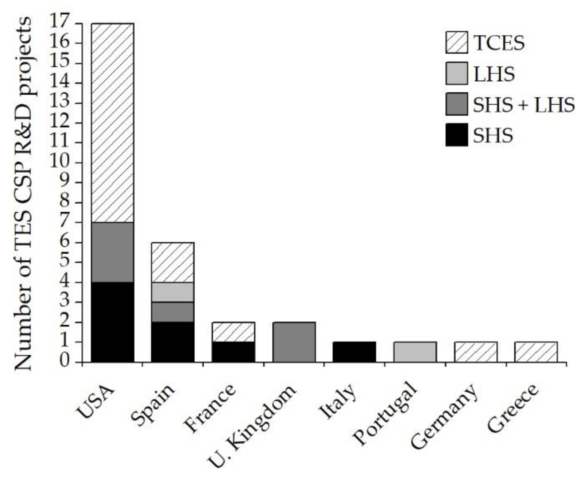
3. European and North American TES CSP R&D Projects Review

In the present section, a review of the completed and ongoing TES CSP R&D projects launched in the last decade (2011–2022) from Europe and North America, which analyze the full integration between CSP, TES and the associated power block, are detailed. Other R&D projects launched in the last decade and not focused on the integration of the full TES CSP system at large scale are not included in this review. These projects oriented to the development of new materials or components required for TES systems, whose application is at small scale or for building and district heating systems, are beyond the scope of the present review.
Before 2011, the CSP-based R&D projects were focused on the integration of SHS and LHS as TES [27]. Molten salts were the most developed storage medium within SHS system, even used as HTF in active direct storage systems configuration [100,101]. Furthermore, research based on molten salts was focused on strategies to minimize its main drawbacks: (i) increasing the storage temperature over 650 °C [102] and (ii) improving the specific heat with embedded ceramic particles [103]. Regarding the CSP TES passive storage configuration, SHS and LHS storage mediums were also investigated. Within SHS the most developed passive storage configurations were: (i) packed-bed system of sand [104] or concrete [105], and (ii) solid graphite modular blocks to achieve operating temperatures up to 1650 °C [106]. Additionally, since 2008, the development of PCMs as LHS increased, transferring the thermal energy by heat exchangers [107,108] or embedded thermosyphon heat pipes [109], even integrating nanoparticles into the PCM to improve the heat transfer efficiency [27].

3.1. Summary of R&D Projects (2011–2022): Timeline and TRL

This section summarizes and compares all the European and North American R&D projects, completed and ongoing, launched in the last decade. Table 7 gathers general information about these TES CSP R&D projects whose technical and economic data will be provided in the following subsections.
The United States of America (USA) is the country with greatest development of TES CSP R&D projects, mainly focused on TCES technology. Meanwhile, Spain has launched the second highest number of TES CSP R&D projects in the last decade (Table 7). Both countries have a long record of developing CSP technology, concentrating the largest number of currently operating CSP facilities deployed in the world with and without TES (i.e., 17 in the USA [25] and 51 in Spain [7]). Figure 4 illustrates the distribution by countries and TES technology of the number of TES CSP R&D projects.
Figure 5 represents a timeline built with the TES CSP R&D projects within the scope of the present study. The upper part comprehends the ongoing TES CSP R&D projects, while the bottom part shows the TES CSP R&D projects already completed since 2011. In addition, the TRL of all the TES CSP R&D projects is shown through a colour scale from low (dark red—TRL 1) to high (dark green—TRL 9) technological readiness level by the end of the project.
The most widespread TES technology among the research projects (almost 55%) between 2011 and 2018 involve the integration of TCES with a CSP plant, reaching a TRL by the end of the project between four and eight; from experimental demonstration to near commercial scale. Within ongoing TES CSP R&D projects, SHS and TCES systems are the most extended with lower TRLs which range from two to six, except for a project which reaches a TRL of eight. Regarding research projects which include LHS as TES, the development level oscillates within lab and pilot scale (TRL 3–5). However, R&D projects involving SHS and LHS TES reached a development level at demonstration scale in the relevant environment (TRL 6).

3.2. TES CSP R&D Projects Completed between 2011–2022

This section gathers the technical and economic information of those TES CSP R&D projects finished from 2011 onwards within Europe and North America. Most of the analyzed projects focus on the complete TES CSP configuration. However, few research projects aim to only develop a specific block of the TES CSP system: storage medium, required equipment for the heat transfer between CSP-TES and TES-power cycle, or new storage concepts. Table 8 summarizes economic and technical data of the TES CSP R&D projects which assess the full integration of the TES with the CSP plant and the power block.

3.2.1. TCS-Power

The overall objective of the Thermochemical Energy Storage for Concentrated Solar Power Plants (TCS-Power) research project was to develop a new, efficient and economically viable TCES for CSP plants, minimizing electricity production costs. Two low-cost and long-term stable TCES systems were proposed within the TCS-Power project: redox and hydroxide. Manganese oxide is the storage medium selected as redox TCES to be integrated into SPT CSP plants, given the high operating temperature (>700 °C). The air is the fluid used as HTF and oxygen carrier for the redox reaction, while calcium oxide is the storage material used as hydroxide TCES integrated into PTC CSP plants, achieving a working temperature between 400 and 600 °C. Molten salts were selected as HTF within hydroxide TCES. However, the hydroxide TCES medium could be used as HTF and TES, given the possibility of the material conveying. Both TCES systems use charge/discharge reactors for the heat transfer between HTF and TES as passive storage TES CSP configuration. The power block associated with both TES systems was the steam Rankine, given its technological maturity. Both TCES systems were evaluated at lab and pilot scale to 10 kW (TRL 4–5). Furthermore, a techno–economic assessment evaluated the TCES up-scaling to commercial scale, being the obtained LCOE of €0.14 and €0.21/kWh under hydroxide and redox TCES systems, respectively. This European R&D project launched in 2011 was coordinated by Deutsches Zentrum für Luft—und Raumfahrt e.V. (DRL) from Germany [111].

3.2.2. RESTRUCTURE

The Redox Materials-based Structured Reactors/Heat Exchangers for Thermo-Chemical Heat Storage Systems in Concentrated Solar Power Plants (RESTRUCTURE) research project aimed to develop a new heat transfer mechanism for the redox TCES systems based on monolithic structures, such as honeycombs or foams partially or totally made of redox materials. The STP CSP technology was selected to integrate the redox TCES system, reaching working temperatures of 1000 °C. The associated power block was a Brayton combined cycle (CC) using air as HTF. The projected storage period was between 6 to 13 h, considering an assessment of up-scaling to commercial scale (70.5 MWe). A LCOE below €0.15/kWhth was estimated through a commercial scale analysis. Before the up-scaling assessment, the redox TCES system was tested under pilot scale at Solar Tower Jülich/STJ research platform in Germany (TRL 4–5). The European R&D project launched in 2011 was coordinated by Ethniko Kentro Erevnas kai Technologikis Anaptyxis (CERTH) from Greece [112].

3.2.3. STORRE

The high temperature thermal energy storage by reversible thermochemical reaction (STORRE) research project aimed to develop the integration of a high-density TCES system in LFR and PTC CSP plants. The calcium hydroxide is the TES material, allowing high-working temperatures up to 550 °C and storage capacities of days. The TES CSP configuration selected is 2-tank active storage, being indirect if there is a HTF between the solar field and the TES or direct if the solid particles are heated into a solar receiver. The reactors required to perform de gas–solid reversible reaction of calcium hydroxide were tested at pilot scale (TRL 3–4). The power block for the up-scaling assessment up to commercial scale (85 MWe) was a steam Rankine with a storage capacity of 6 and 13 h. The European R&D project launched in 2012 was coordinated by Commissariat a l’Energie Atomique et aux Energies Alternatives (CEA) from France [113].

3.2.4. CaL-TES

The Demonstration of High-Temperature Calcium-Based Thermochemical Energy Storage System for Use with Concentrating Solar Power Facilities (CaL-TES) research project aimed to develop a low cost TCES system to couple with sCO2 power cycles integrated into SPT CSP plants. A carbonate TCES system based on calcium oxide was selected to achieve high operating temperatures for the power block up to 720 °C. The same packed-bed reactor is used to perform the reversible reaction. Under the endothermic reaction, the HTF transfers heat to the reactor to decompose limestone into CaO and CO2, diverting the gas to storage. The exothermic reaction occurs when CO2 from storage reacts with CaO in the reactor to retrieve the stored energy and to be transferred to the HTF. Thus, the TES cSP configuration is a passive storage, considering (i) molten salts or liquid metal as HTF between the packed-bed reactor and an intermediate heat exchanger and (ii) sCO2 as HTF between the intermediate heat exchanger and the power block. A demonstration up-scaling of 100 MWh will be expected beyond the project (TRL 7–8). The American R&D project launched in 2015 was coordinated by the Southern Research Institute (SRI) [121].

3.2.5. NEXT-CSP

The NEXT-CSP research project (High temperature concentrated solar thermal power plan with particle receiver and direct thermal storage) aimed to validate an industrial pilot plant (TRL5) tested at Thémis SPT experimental facility (France) for integrating new technology in CSP plants. The Centre National de la Recherche Scientifique (CNRS) in France coordinated the European R&D project launched in 2016 [122].
A fluidized particle in-tube concept, first published in 1980, was developed to design the solar receiver (scaling up to 50 MWth per single unit) to heat the TES up to 650–750 °C [123]. The solar receiver with fluidized particle recirculation was previously demonstrated at 150 KW in the CSP2 (Concentrated Solar Power in Particles) research project [124]. Silicon carbide solid particles were used as TES medium and HTF, as two-tank active direct TES CSP configuration. The cold and hot particles tanks were interconnected through a particle-pressurized air fluidized bed heat exchanger [123]. This novel storage configuration was coupled to a gas turbine reaching a power block efficiency of 46% [125]. However, the integration of subcritical steam or air Brayton power cycles also achieved good efficiencies (up to 41% [126] and 39% [127], respectively) with lower energy penalties. Additionally, the integration of supercritical steam or CO2 cycles could minimize energy penalties and cost of the TES CSP plant. For future work, the large-scale facility (>100 MWe) using multiples SPTs will be developed and demonstrated [123].

3.2.6. NEXTOWER

The NEXTOWER research project (Advanced materials solutions for next generation high efficiency concentrated solar power (CSP) tower system) aimed to demonstrate the durability over 20 years of ceramic materials for large CSP air-based SPT (>5 MWe). The air is heated up to 800 °C in the solar receiver and the thermal energy is transferred to an innovative single tank thermocline with liquid metal as TES medium by an air–lead heat exchanger. The TES CSP configuration is an indirect active system using air as HTF. The liquid metal storage material is based on liquid lead stored in new non-corrosive alumina forming steels, which has been transferred from nuclear fission technology. The liquid lead as TES was installed and proved at demo scale TRL 6 (SOLEAD) in Plataforma Solar de Almería (Spain). The high temperature achieved by the storage medium extends the thermal applications of CSP plants. Regarding the association of high-temperature power blocks to the CSP plant, the easiest integration would be achieved with working fluids such as compressed gases or supercritical fluids. The European R&D project launched in 2017 was coordinated by Italian National Agency for New Technologies, Energy and Sustainable Economic Development (ENEA) [133].

3.2.7. IN-POWER

The Advanced Materials technologies to QUADRUPLE the Concentrated Solar Thermal current POWER GENERATION (IN-POWER) European R&D project aimed to develop new technology solutions for LFR and PTC CSP plants to improve the efficiency and to minimize the costs. Regarding energy storage, a combination of SHS and LHS media is investigated. The TES CSP configuration is a molten salt (60% NaNO3 and 40% KNO3) single-tank thermocline active storage with encapsulated PCM (Aluminium silicon). The molten salts act as HTF to the PCM as passive storage TES CSP configuration. This new SHS-LHS hybrid TES system (i) minimizes the charge/discharge cyclical degradation and (ii) maximizes the storage capacity compared to the same volume of a classic molten salts single-tank thermocline system. Thus, the TES system could be reduced and also its cost (LCOE beyond 2020 €0.10/kWh), testing in LFR and PTC pilot plants (TRL 6) for DSG. The European R&D project launched in 2017 was coordinated by Acondicionamiento Tarrasense Asociación (LEITAT) from Spain [134].

3.2.8. NewSOL

The main objective of New StOrage Latent and sensible concept for high efficient CSP Plants (NewSOL) research project is to develop new materials for energy storage in (CSP) plants. Two innovative concrete storage media were investigated for integration into existing or new PTC CSP plants, reaching storage temperatures up to 550 °C. A concrete module tank is proposed as SHS medium for existing CSP plants, using a new Ca-ternary molten salt mixture as HTF circulating inside the embedded pipes (passive storage TES CSP configuration with a storage capacity of 1600 kWhth). Under new CSP plants, a Ca-ternary molten salt single-tank thermocline with concrete walls and encapsulated PCMs is implemented as a SHS and LHS system within an active storage TES CSP configuration, using the new molten salt mixture as HTF for the PCM passive storage medium. Thus, the new thermocline system replaces classic steel walls with cement (i) to minimize cyclic thermocline degradation and (ii) to improve the storage performance. The new SHS-LHS TES system was implemented as a prototype at demo scale (TRL 5–6) in Évora Molten Salts Platform (Portugal), producing 8 additional hours of steam to the associated power block. The NewSOL European R&D project launched in 2017, led by Universidade de Évora (UEv) from Portugal [135].

3.2.9. SOCRATCES

The SOlar Calcium-looping integRAtion for Thermo-Chemical Energy Storage (SOCRATCES) research project focused on reducing the intermittency in electricity production of SPT CSP plants, using the advantages of calcium looping (CaL) compared to other types of technologies used as TCES, such as the low price of CaCO3 (€10/ton) and its wide availability. In addition, the equipment used in the CaL system was previously developed as CO2 capture technology. Solar energy decomposes limestone into CO2 and CaO at calciner receiver to be later independently stored, even at ambient temperature. When electric demand is high, the stored products are fed to the carbonator reactor, retrieving thermal energy to the power block. The TES CSP configuration can be considered as passive storage, with heat exchangers needed between the storage tanks and the main reactors. The high working temperatures achieved (600 and 1000 °C) could improve the power block efficiency associated to a SPT CSP plant. Among the power cycles assessed, the best promising option for upscaling the CaL TCES system is the closed-loop CO2 Brayton cycle, reaching overall efficiencies up to 45%. The CaL TCES system has been tested in the relevant environment at pilot scale (TRL 5). The LCOE expected will be lower than 0.07€/kWh at commercial scale [136]. The European R&D project launched in 2018 was led by University of Seville (USe) from Spain [137].

3.2.10. Other TES CSP R&D Projects (Materials, Concepts, Technology)

Since 2011, TES research projects focused on the development of concepts, materials or heat transfer technologies have also been investigated as an application to CSP plants. Regarding LHS TES systems, different structures to store PCM were researched. The University of South Florida (USFl) from the USA validated at lab scale encapsulated PCM into a packed-bed system as passive storage [110]. Furthermore, Argonne National Laboratory (ArNL) from the USA developed a 2-phase project from lab to demonstration scale to validate PCM using graphite foam to improve its thermal efficiency, infiltrating MgCl2 into the graphite pores [115]. Moreover, the European NPMSSES research project (United Kingdom) researched the introduction of nanoparticles into a PCM (solar salt) to improve its thermo–physical properties at lab scale [130]. Another European R&D project (AMADEUS from Spain) developed synthetic PCM, demonstrating at proof of concept the thermal energy retrieval through a hybrid thermionic–photovoltaic converter to produce electricity [131]. Regarding the application of LHS TES system to low temperature solar fields, the European THERMES R&D project (United Kingdom) developed a microemulsion of PCM to act as HTF and TES at lab scale [138].
Additionally, the main developed TCES technologies were based on two systems: hydride and metal oxides. The Savannah River National Laboratory (SRNL) and Brayton Energy (BE) institutions (USA) validated a metal hydride TCES at bench scale to be integrated into a CSP with an associated high temperature sCO2 power block [114,119]. Binary metal chalcogenide as TCES system in a modular reactor was developed by Los Alamos National Laboratory (AlNL) from the USA to achieve working temperatures up to 750 °C [120]. Regarding metal oxide systems, the carbonate one was developed at lab and bench scale by University of Florida (UFl) and Southern Research Institute (SRI) from the USA, respectively. The strontium carbonate TCES system reached temperature up to 1000 °C (UFl) [116], while the regenerative carbonate system developed by SRI operated at medium temperature (650–850 °C) [117]. Besides, new TCES materials as perovskites researched by Colorado School of Mines (CSM) from the USA [118] and SesPER R&D project (Spain) [132], achieving high storage temperatures (up to 1200 °C) at advanced TRL 6 to 8. However, new TES similar to SHS system have been developed by SOLSTORE R&D project (Spain), providing extra thermal energy by the enthalpy of a solid-state reaction [128,129].

3.3. Ongoing TES CSP R&D Projects Lauched between 2011–2022

This section gathers the ongoing TES CSP R&D projects launched from 2011 within the European and North American regions. The currently active TES CSP R&D projects focuses on (i) new SHS materials and (ii) the growing use of TCES technology. Table 9 summarized the main relevant data of the current active TES CSP R&D projects since 2011.
The National Renewable Energy Laboratory (NREL), from the USA, promotes a demonstration scale research project (TRL 6) with 2-tank indirect active storage TES CSP configuration, using new molten chloride salts as SHS medium (up to 12 h of storage capacity) and liquid-metal sodium as HTF to achieve a high temperature (740 °C) for the associated power block (sCO2) to the SPT CSP plant [139]. The new molten chloride salts are also developed by Oak Ridge National Laboratory (ORNL), from the USA, in a single-tank thermocline TES CSP configuration to reduce costs [142]. The thermocline concept will be developed by NEWCLINE (CSP-ERANET) R&D project, using PCM at pilot scale (TRL 5) [141]. The integration of a sCO2 power cycle is developed in other R&D projects, using as TES (i) composite PCM (Brayton Energy (BE), USA) [140], (ii) multiple TCES to suitably dispatch electricity (Arizona State University (ArSU), USA) [27] or (iii) solid material to be demonstrated at full scale (5 MW), such as packed-bed of rocks (EDISUN (USA)) [27]. Regarding the BE research project, the main objective is to test a new heat exchanger design, given as TES the graphite foam-based PCM developed by ArNL from 2012 to 2018. The development of TCES research projects continues to expand, increasing the working temperature up to 1300 °C with redox reactions (Michigan State University (MiSU), USA) [27] or improving the storage capacity at ambient temperature of a new molten carbonate mixture (Savannah River National Laboratory (SRNL), USA) [27]. Finally, research on improving the heat transfer efficiency of packed-bed passive storage systems is developed by Montana State University (MoSU), from the USA [27].

4. Discussion and Conclusions

The problem of intermittency in energy production associated to the CSP facilities will only be solved by increasing the use of TES. More than a half of the currently operating CSP facilities have a TES system, mainly based on molten salts SHS medium. Despite molten salts having a high TRL for high-temperature applications, natural rocks will be a promising SHS medium given their low storage cost. Within LHS systems, high-temperature PCM has been tested in the operational environment, being one of the potential TES systems when its heat transfer ratio and storage cost are improved. Regarding the TCES system, issues such as the reactor design and the reaction control are being investigated at TRL 4. When a greater development of the chemical reactions involving TCES is reached, a lower storage cost is expected even below SHS and LHS materials.
Almost all of the European and North American TES CSP R&D projects completed before 2011 implemented the conventional configuration related to the first and second generation of CSP plants associated with a steam Rankine power block, including (i) molten salts as TES, (ii) thermal oil as HTF and (iii) PTC technology in solar fields. Firstly, even though LCOE of PTC technology is one of the highest, its advantageous properties proven on a commercial scale will boost its leadership in the CSP market. Secondly, despite the 2-tank indirect active storage system being the most commercially extended, the steam accumulator format within the active direct storage system allows direct use of steam generated in the solar field for storage and production of electrical energy through the steam power cycle. Moreover, savings of 35% of the cost of the TES system can be achieved by using a single tank. The major issue of the active storage systems are the limitations associated with the media currently used in commercial CSP plants, such as the high freezing point of common molten salts, the low thermal conductivity of water, as well as the high costs of conventional molten salts and pressurized water storage tanks. Thus, the R&D projects launched after 2011 in Europe and North America developed new TES, using TES CSP configurations based on passive storage and single tank thermocline active storage to minimize the LCOE of the CSP facilities, being able to use low-cost materials and achieving better heat transfer. Furthermore, one of the most important advantages is the inclusion of a thermocline system in the passive storage using molten salts and PCM, leading to a new storage configuration with lower LCOE. Regarding HTF, the use of TES as HTF or even air is advantageous over the use of conventional molten salts, minimizing the costs of electricity production. Nevertheless, since there is a high number of R&D projects with high-temperature TCES storage systems, the associated CSP technologies are mainly based on SPT and PTC. One of the limitations of high-temperature TCES storage systems focuses on the development of materials that can withstand these working temperatures. The USA and Spain are the leading countries in the implementation of research projects related to the integration of TES in CSP facilities with an associated power cycle for large-scale electricity production. Their great track record of technology development in CSP plants endorses both countries, accounting for almost 60% of the currently operating CSP plants.
Regarding SHS media, new molten salts allow to achieve operating temperatures up to 740 °C. In addition, novel storage media based on liquid metal or solids (i.e., particles or rocks) begin to develop from pilot to sub-commercial scale at the STP CSP plants. Similarly, the combination of SHS and LHS within LFR and PTC CSP facilities are under development at demo scale. The LHS system using different PCMs could increase the thermal energy that could be stored. Furthermore, new lab-scale research based on introducing nanoparticles improves the thermophysical properties of the PCM. The TCES-based R&D projects extended are related to hydroxide, carbonate and redox TCES systems, reaching working temperatures up to 1000 °C and a level of development from demo to sub-commercial scale.
The TCES systems have been the most investigated TES technologies in the last decade, given the low cost of the storage medium and the high temperatures achieved when retrieving the stored thermal energy. Thus, new high-temperature power blocks can be implemented into the TES CSP facilities to improve the overall plant efficiency, such as Brayton or supercritical CO2 cycles. The main objective of the largest budget allocated to an ongoing TES CSP R&D project is to develop the sCO2 power cycle associated with CSP plants on a commercial scale.

5. Future Directions

The next steps of research in TES CSP integration in the near future will be focused on the upscaling, from demo to commercial stage, the SPT and PTC CSP facilities, using (i) high energy density, low-cost TES materials for larger storage time with minimal energy losses (i.e., solid SHS as passive storage, combination of liquid SHS and PCM as LHS medium, carbonate or redox TCES systems) and (ii) high efficiency power blocks (i.e., supercritical or Brayton) to even minimize the LCOE of the CSP facility below 0.05 €/kWh. Solid particles or packed-beds of rocks, with SHS as passive storage, may be able to reduce the investment cost of the CSP facility. Among LHS systems, the newly developed PCMs together with the use of new low-freezing point molten salts will set a new configuration between the passive and active system, minimizing the storage size and therefore associated costs. Notably, the TCES systems will grow exponentially, leading the conversion of CSP facilities to base-load plants with safe and uninterrupted electricity production.

Author Contributions

Conceptualization, S.P. and P.L.; methodology, S.P.; formal analysis, P.L. and L.M.R.; investigation, S.P.; resources, S.P.; data curation, S.P.; writing—original draft preparation, S.P.; writing—review and editing, P.L.; visualization, S.P.; supervision, P.L. and L.M.R. All authors have read and agreed to the published version of the manuscript.

Funding

This research was funded by Ministerio de Ciencia, Innovación y Universidades, grant number FPU 2017/03902. This research was also funded by Horizon 2020 Framework Programme (GA No. 727348, SOCRATCES project) and Gobierno de Aragón (Research Group DGA 959 T46_20R).

Data Availability Statement

Not applicable.

Conflicts of Interest

The authors declare no conflict of interest. The funders had no role in the design of the study; in the collection, analyses, or interpretation of data; in the writing of the manuscript; or in the decision to publish the results.

Nomenclature

Symbols
afraction reacted, -
cspecific heat, J/kg∙K
fmelt fraction, -
mmass of storage medium, kg
Qheat, J
Ttemperature, °C
∆Hheat of reaction, J/kg
∆qlatent heat of fusion, J/kg
Subscripts and superscripts
ffinal
Iinitial
mmelting
maxmaximum
outoutlet
pconstant pressure
plliquid phase
pssolid phase
rreaction
sstorage/stored
Acronyms and abbreviations
CCCombined Cycle
CORDISCommunity Research and Development Information Service
CSPConcentrating Solar Power
GHGGreenhouse Gases
HTHeat Transfer
HTFHeat Transfer Fluid
IPCCIntergovernmental Panel on Climate Change
LCOELevelized Cost Of Electricity
LFRLinear Fresnel Reflectors
LHSLatent Heat Storage
PDCParabolic Dish Collectors
PMCsPhase Change Materials
PTCParabolic Trough Collectors
RESRenewable Energy Sources
R&DResearch and Development
sCO2Supercritical CO2
SETOSolar Energy Technologies Office
SHSSensible Heat Storage
SPTSolar Power Towers
TCESThermochemical Energy Storage
TESThermal Energy Storage
TRLTechnology Readiness Level
USAUnited States of America

Appendix A. List of R&D Projects, Co-Ordinators and Abbreviations

Table A1. List of R&D projects name and abbreviations.
Abbreviation Project Name
AMADEUSNext GenerAtion MateriAls and Solid State DevicEs for Ultra High Temperature Energy Storage and Conversion
BMC-TESBinary Metal Chalcogenides for High Temperature Thermal Storage
CaL-TESDemonstration of High-Temperature Calcium-Based Thermochemical Energy Storage System for Use with Concentrating Solar Power Facilities
CSP-ERANET (Newcline)Advanced thermocline concepts for thermal energy storage for CSP
DDI-TESDevelopment and Demonstration of an Innovative Thermal Energy Storage System for Baseload Power Generation
EC-TESEutectic Carbonates for Low Cost-Efficient Thermochemical Heat Storage System
ELEM-TESEfficiently Leveraging Equilibrium Mechanisms for Engineering New Thermochemical Storage
EWSCh-TESEconomic Weekly and Seasonal Thermochemical and Chemical Energy Storage for Advanced Power Cycles
FULL-TESDevelopment, Build and Operation of a Full-Scale, Nominally 5MWe, Supercritical Carbon Dioxide Power Cycle Coupled with Solid Media Energy Storage
HELH-TESHigh Efficiency Latent Heat Based Thermal Energy Storage System Compatible with Supercritical Carbon Dioxide Power Cycle
HTMS-TESSimplified High-Temperature Molten Salt Concentrating Solar Power Plant Preconceptual Design
IN-POWERAdvanced Materials technologies to QUADRUPLE the Concentrated Solar Thermal current POWER GENERATION
ISR-TESIntegrated Solar Receiver with Thermal Storage for an sCO2 Power Cycle
LMMH-TESLow-Cost Metal Hydride Thermal Energy Storage System for Concentrating Solar-Thermal Power Systems
LPP-SSLiquid-Phase Pathway to SunShot
NewSOLNew StOrage Latent and sensible concept for high efficient CSP Plants
NEXT-CSPHigh Temparature concentrated solar thermal power plan with particle receiver and direct thermal storage
NEXTOWERAdvanced materials solutions for next generation high efficiency concentrated solar power (CSP) tower systems
NPMSSESNanoparticle Enhanced Molten Salts for Solar Energy Storage
PBEfficient Thermal Energy Storage with Radial Flow in Packed Beds
RC-TESRegenerative Carbonate-Based Thermochemical Energy Storage System for Concentrating Solar Power
RESTRUCTURERedox Materials-based Structured Reactors/Heat Exchangers for Thermo-Chemical Heat Storage Systems in Concentrated Solar Power Plants
SC-TESCarbon Dioxide Shuttling Thermochemical Storage Using Strontium Carbonate
SesPERSolar Energy Storage PERovskites
SOCRATCESSOlar Calcium-looping integRAtion for Thermo-Chemical Energy Storage
SOLSTORESolid-state reactions for thermal energy storage
SS-TESSolid State Solar Thermochemical Fuel for Long-Duration Storage
STORREHigh temperature thermal energy Storage by Reversible thermochemical Reaction
TCS-PowerThermochemical Energy Storage for Concentrated Solar Power Plants
TES-HEIntegrated Thermal Energy Storage Heat Exchanger for Concentrating Solar Power Applications
THERMESA new generation high temperature phase change microemulsion for latent thermal energy storage in dual loop solar field
Table A2. List of R&D project coordinators and abbreviations.
Abbreviation Project Coordinator
AGENEXAgencia Extremeña de la Energía
AlNLLos Alamos National Laboratory
ArNLArgonne National Laboratory
ArSUArizona State University
BEBrayton Energy
CEACommissariat a l’Energie Atomique et aux Energies Alternatives
CERTHEthniko Kentro Erevnas kai Technologikis Anaptyxis
CICCentro de Investigación Cooperativa de Energías Alternativas
CNRSCentre National de la Recherche Scientifique
CSICAgencia Estatal Consejo Superior de Investigaciones Científicas
CSMColorado School of Mines
DRLDeutsches Zentrum für Luft-und Raumfahrt e.V.
EDISUNEdisun
ENEAItalian National Agency for New Technologies, Energy and Sustainable Economic Development
LEITATAcondicionamiento Tarrasense Asociación
MiSUMichigan State University
MoSUMontana State University
NRELNational Renewable Energy Laboratory
ORNLOak Ridge National Laboratory
SRISouthern Research Institute
SRNLSavannah River National Laboratory
UBirUniversity of Birmingham
UEvUniversidade de Évora
UFlUniversity of Florida
ULeUnivertisty of Leeds
UPMUniversidad Politécnica de Madrid
USeUniversidad de Sevilla
USFlUniversity of South Florida

References

  1. IPCC. Climate Change 2022: Mitigation of Climate Change. Contribution of Working Group III to the Sixth Assessment Report of the Intergovernmental Panel on Climate Change; Shukla, P.R., Skea, J., Slade, R., Al Khourdajie, A., van Diemen, R., McCollum, D., Pathak, M., Some, S., Vyas, P., Fradera, R., et al., Eds.; Cambridge University Press: Cambridge UK; New York, NY, USA, 2022. [Google Scholar]
  2. Renewables 2022. Global Status Report; Zervos, A., Adib, R., Eds.; REN21 Secretariat: Paris, France, 2022; ISBN 978-3-948393-04-5. [Google Scholar]
  3. Morante, J.R. El Almacenamiento de Electricidad—Fundación Gas Natural Fenosa; Fundación Gas Natural Fenosa, Ed.; Fundación Gas Natural Fenosa: Barcelona, Spain, 2014; ISBN 9788469598979. [Google Scholar]
  4. Peón Menendez, R. Optimización del Control del Sistema de Almacenamiento Térmico en Centrales Solares Termoeléctricas; Universidad de Oviedo: Oviedo, Spain, 2012. [Google Scholar]
  5. Kunwer, R.; Pandey, S.; Pandey, G. Technical Challenges and Their Solutions for Integration of Sensible Thermal Energy Storage with Concentrated Solar Power Applications—A Review. Process Integr. Optim. Sustain. 2022, 6, 559–585. [Google Scholar] [CrossRef]
  6. International Renewable Energy Agency (IRENA). Innovation Outlook: Thermal Energy Storage; International Renewable Energy Agency (IRENA): Abu Dhabi, United Arab Emirates, 2020; ISBN 978-92-9260-279-6. [Google Scholar]
  7. Goyal, N.; Aggarwal, A.; Kumar, A. Concentrated solar power plants: A critical review of regional dynamics and operational parameters. Energy Res. Soc. Sci. 2022, 83, 102331. [Google Scholar] [CrossRef]
  8. Kraemer, S. CSP Doesn’t Compete with PV—It Competes with Gas. Available online: Solarpaces.org/csp-competes-with-natural-gas-not-pv/ (accessed on 1 July 2022).
  9. Cabeza, L.F.; de Gracia, A.; Zsembinszki, G.; Borri, E. Perspectives on thermal energy storage research. Energy 2021, 231, 120943. [Google Scholar] [CrossRef]
  10. Islam, T.; Huda, N.; Abdullah, A.B.; Saidur, R. A comprehensive review of state-of-the-art concentrating solar power (CSP) technologies: Current status and research trends. Renew. Sustain. Energy Rev. 2018, 91, 987–1018. [Google Scholar] [CrossRef]
  11. Achkari, O.; El Fadar, A. Latest developments on TES and CSP technologies—Energy and environmental issues, applications and research trends. Appl. Therm. Eng. 2020, 167, 114806. [Google Scholar] [CrossRef]
  12. Shahabuddin, M.; Alim, M.A.; Alam, T.; Mofijur, M.; Ahmed, S.F.; Perkins, G. A critical review on the development and challenges of concentrated solar power technologies. Sustain. Energy Technol. Assess. 2021, 47, 101434. [Google Scholar] [CrossRef]
  13. Calderón, A.; Barreneche, C.; Prieto, C.; Segarra, M.; Fernández, A.I. Concentrating Solar Power Technologies: A Bibliometric Study of Past, Present and Future Trends in Concentrating Solar Power Research. Front. Mech. Eng. 2021, 7, 682592. [Google Scholar] [CrossRef]
  14. Palacios, A.; Barreneche, C.; Navarro, M.E.; Ding, Y. Thermal energy storage technologies for concentrated solar power—A review from a materials perspective. Renew. Energy 2020, 156, 1244–1265. [Google Scholar] [CrossRef]
  15. Alnaimat, F.; Rashid, Y. Thermal energy storage in solar power plants: A review of the materials, associated limitations, and proposed solutions. Energies 2019, 12, 4164. [Google Scholar] [CrossRef] [Green Version]
  16. Calderón, A.; Palacios, A.; Barreneche, C.; Segarra, M.; Prieto, C.; Rodriguez-Sanchez, A.; Fernández, A.I. High temperature systems using solid particles as TES and HTF material: A review. Appl. Energy 2018, 213, 100–111. [Google Scholar] [CrossRef]
  17. El Alami, K.; Asbik, M.; Agalit, H. Identification of natural rocks as storage materials in thermal energy storage (TES) system of concentrated solar power (CSP) plants—A review. Sol. Energy Mater. Sol. Cells 2020, 217, 110599. [Google Scholar] [CrossRef]
  18. Opolot, M.; Zhao, C.; Liu, M.; Mancin, S.; Bruno, F. A review of high temperature (≥ 500 °C) latent heat thermal energy storage. Renew. Sustain. Energy Rev. 2022, 160, 112293. [Google Scholar] [CrossRef]
  19. Liu, M.; Omaraa, E.S.; Qi, J.; Haseli, P.; Ibrahim, J.; Sergeev, D.; Müller, M.; Bruno, F.; Majewski, P. Review and characterisation of high-temperature phase change material candidates between 500 C and 700 °C. Renew. Sustain. Energy Rev. 2021, 150, 111528. [Google Scholar] [CrossRef]
  20. André, L.; Abanades, S. Recent Advances in Thermochemical Energy Storage via Solid–Gas Reversible Reactions at High Temperature. Energies 2020, 13, 5859. [Google Scholar] [CrossRef]
  21. Carrillo, A.J.; González-Aguilar, J.; Romero, M.; Coronado, J.M. Solar Energy on Demand: A Review on High Temperature Thermochemical Heat Storage Systems and Materials. Chem. Rev. 2019, 119, 4777–4816. [Google Scholar] [CrossRef] [PubMed]
  22. Zsembinszki, G.; Solé, A.; Barreneche, C.; Prieto, C.; Fernández, A.; Cabeza, L. Review of Reactors with Potential Use in Thermochemical Energy Storage in Concentrated Solar Power Plants. Energies 2018, 11, 2358. [Google Scholar] [CrossRef] [Green Version]
  23. Alva, G.; Lin, Y.; Fang, G. An overview of thermal energy storage systems. Energy 2018, 144, 341–378. [Google Scholar] [CrossRef]
  24. Pelay, U.; Luo, L.; Fan, Y.; Stitou, D.; Rood, M. Thermal energy storage systems for concentrated solar power plants. Renew. Sustain. Energy Rev. 2017, 79, 82–100. [Google Scholar] [CrossRef]
  25. Concentrating Solar Power Projects. National Renewable Energy Laboratory. Available online: https://solarpaces.nrel.gov/projects (accessed on 1 July 2022).
  26. CORDIS. EU Research Results. European Commission. Available online: https://cordis.europa.eu/projects/en (accessed on 15 July 2022).
  27. Solar Energy Research Database. Solar Energy Technologies Office. U.S. Department of Energy. Available online: https://www.energy.gov/eere/solar/solar-energy-research-database (accessed on 15 July 2022).
  28. Teske, S.; Leung, J. Solar Thermal Electricity—Global Outlook 2016; Rochon, E., Ed.; Greenpeace International: Amsterdam, The Netherlands; European Solar Thermal Electricity Association (ESTELA): Bruxelles, Belgium; SolarPACES Secretariate: Almeria, Spain, 2016. [Google Scholar]
  29. Pavlovic, T.; Radonjic, I. A review of concentrating solar power plants in the world and their potential use in Serbia. Renew. Sustain. Energy Rev. 2012, 16, 12. [Google Scholar] [CrossRef]
  30. Chacartegui, R.; Alovisio, A.; Ortiz, C.; Valverde, J.M.; Verda, V.; Becerra, J.A. Thermochemical energy storage of concentrated solar power by integration of the calcium looping process and a CO2 power cycle. Appl. Energy 2016, 173, 589–605. [Google Scholar] [CrossRef]
  31. Ortiz, C.; Chacartegui, R.; Valverde, J.M.; Alovisio, A.; Becerra, J.A. Power cycles integration in concentrated solar power plants with energy storage based on calcium looping. Energy Convers. Manag. 2017, 149, 815–829. [Google Scholar] [CrossRef]
  32. Tesio, U.; Guelpa, E.; Verda, V. Integration of thermochemical energy storage in concentrated solar power. Part 2: Comprehensive optimization of supercritical CO2 power block. Energy Convers. Manag. 2020, 6, 100038. [Google Scholar] [CrossRef]
  33. Arias, I.; Cardemil, J.; Zarza, E.; Valenzuela, L.; Escobar, R. Latest developments, assessments and research trends for next generation of concentrated solar power plants using liquid heat transfer fluids. Renew. Sustain. Energy Rev. 2022, 168, 112844. [Google Scholar] [CrossRef]
  34. Barlev, D.; Vidu, R.; Stroeve, P. Innovation in concentrated solar power. Sol. Energy Mater. Sol. Cells 2011, 95, 2703–2725. [Google Scholar] [CrossRef]
  35. Wagner, S.J.; Rubin, E.S. Economic implications of thermal energy storage for concentrated solar thermal power. Renew. Energy 2014, 61, 81–95. [Google Scholar] [CrossRef]
  36. Kuravi, S.; Trahan, J.; Goswami, D.Y.; Rahman, M.M.; Stefanakos, E.K. Thermal energy storage technologies and systems for concentrating solar power plants. Prog. Energy Combust. Sci. 2013, 39, 285–319. [Google Scholar] [CrossRef]
  37. Dizaji, H.B.; Hosseini, H. A review of material screening in pure and mixed-metal oxide thermochemical energy storage (TCES) systems for concentrated solar power (CSP) applications. Renew. Sustain. Energy Rev. 2018, 98, 9–26. [Google Scholar] [CrossRef]
  38. Nazir, H.; Batool, M.; Bolivar, F.J.; Isaza-ruiz, M.; Xu, X.; Vignarooban, K.; Phelan, P.; Kannan, A.M. Recent developments in phase change materials for energy storage applications: A review. Int. J. Heat Mass Transf. 2019, 129, 491–523. [Google Scholar] [CrossRef]
  39. Liu, C.; Rao, Z. Challenges in various thermal energy storage technologies. Sci. Bull. 2017, 62, 231–233. [Google Scholar] [CrossRef]
  40. Chen, X.; Zhang, Z.; Qi, C.; Ling, X.; Peng, H. State of the art on the high-temperature thermochemical energy storage systems. Energy Convers. Manag. 2018, 177, 792–815. [Google Scholar] [CrossRef]
  41. Sarbu, I.; Sebarchievici, C. A Comprehensive Review of Thermal Energy Storage. Sustainability 2018, 10, 191. [Google Scholar] [CrossRef] [Green Version]
  42. Kumar, A.; Shukla, S.K. A Review on Thermal Energy Storage Unit for Solar Thermal Power Plant Application. Energy Procedia 2015, 74, 462–469. [Google Scholar] [CrossRef] [Green Version]
  43. Khare, S.; Dell’Amico, M.; Knight, C.; McGarry, S. Selection of materials for high temperature sensible energy storage. Sol. Energy Mater. Sol. Cells 2013, 115, 114–122. [Google Scholar] [CrossRef]
  44. Tiddens, A.; Röger, M.; Stadler, H.; Hoffschmidt, B. Air return ratio measurements at the solar tower Jülich using a tracer gas method. Sol. Energy 2017, 146, 351–358. [Google Scholar] [CrossRef] [Green Version]
  45. Gil, A.; Medrano, M.; Martorell, I.; Lázaro, A.; Dolado, P.; Zalba, B.; Cabeza, L.F. State of the art on high temperature thermal energy storage for power generation. Part 1-Concepts, materials and modellization. Renew. Sustain. Energy Rev. 2010, 14, 31–55. [Google Scholar] [CrossRef]
  46. Aggarwal, A.; Goyal, N.; Kumar, A. Thermal characteristics of sensible heat storage materials applicable for concentrated solar power systems. Mater. Today Proc. 2021, 47, 5812–5817. [Google Scholar] [CrossRef]
  47. El Alami, K.; Asbik, M.; Boualou, R.; Ouchani, F.-Z.; Agalit, H.; Bennouna, E.G.; Rachidi, S. A critical overview of the suitability of natural Moroccan rocks for high temperature thermal energy storage applications: Towards an effective dispatching of concentrated solar power plants. J. Energy Storage 2022, 50, 104295. [Google Scholar] [CrossRef]
  48. Gutierrez, A.; Miró, L.; Gil, A.; Rodríguez-Aseguinolaza, J.; Barreneche, C.; Calvet, N.; Py, X.; Inés Fernández, A.; Grágeda, M.; Ushak, S.; et al. Advances in the valorization of waste and by-product materials as thermal energy storage (TES) materials. Renew. Sustain. Energy Rev. 2016, 59, 763–783. [Google Scholar] [CrossRef] [Green Version]
  49. Ortega-Fernández, I.; Calvet, N.; Gil, A.; Rodríguez-Aseguinolaza, J.; Faik, A.; D’Aguanno, B. Thermophysical characterization of a by-product from the steel industry to be used as a sustainable and low-cost thermal energy storage material. Energy 2015, 89, 601–609. [Google Scholar] [CrossRef]
  50. Al-Azawii, M.M.S.; Alhamdi, S.F.H.; Braun, S.; Hoffmann, J.F.; Calvet, N.; Anderson, R. Experimental study on packed-bed thermal energy storage using recycled ceramic as filler materials. J. Energy Storage 2021, 44, 103375. [Google Scholar] [CrossRef]
  51. Bradshaw, R.W.; Siegel, N.P. Molten nitrate salt development for thermal energy storage in parabolic trough solar power systems. In Proceedings of the ASME 2008 2nd International Conference on Energy Sustainability, Jacksonville, FL, USA, 10–14 August 2008; Volume 2, pp. 631–637. [Google Scholar]
  52. Peng, Q.; Wei, X.; Ding, J.; Yang, J.; Yang, X. High-temperature thermal stability of molten salt materials. Int. J. Energy Res. 2008, 32, 1164–1174. [Google Scholar] [CrossRef]
  53. Zhao, C.Y.; Wu, Z.G. Thermal property characterization of a low melting-temperature ternary nitrate salt mixture for thermal energy storage systems. Sol. Energy Mater. Sol. Cells 2011, 95, 3341–3346. [Google Scholar] [CrossRef]
  54. Vignarooban, K.; Xu, X.; Arvay, A.; Hsu, K.; Kannan, A.M. Heat transfer fluids for concentrating solar power systems—A review. Appl. Energy 2015, 146, 383–396. [Google Scholar] [CrossRef]
  55. Caraballo, A.; Galán-Casado, S.; Caballero, Á.; Serena, S. Molten salts for sensible thermal energy storage: A review and an energy performance analysis. Energies 2021, 14, 1197. [Google Scholar] [CrossRef]
  56. Ding, W.; Bauer, T. Progress in Research and Development of Molten Chloride Salt Technology for Next Generation Concentrated Solar Power Plants. Engineering 2021, 7, 334–347. [Google Scholar] [CrossRef]
  57. Aljaerani, H.A.; Samykano, M.; Saidur, R.; Pandey, A.K.; Kadirgama, K. Nanoparticles as molten salts thermophysical properties enhancer for concentrated solar power: A critical review. J. Energy Storage 2021, 44, 103280. [Google Scholar] [CrossRef]
  58. Pistocchini, L.; Size, P.M.; Plant, P.; Motta, M.; Lambruschini, V. Feasibility Study of an Innovative Dry-Cooling System With Phase-Change Material Storage for Concentrated Solar. Sol. Energy Eng. 2011, 133, 031010. [Google Scholar] [CrossRef]
  59. González-Roubaud, E.; Pérez-Osorio, D.; Prieto, C. Review of commercial thermal energy storage in concentrated solar power plants: Steam vs. molten salts. Renew. Sustain. Energy Rev. 2017, 80, 133–148. [Google Scholar] [CrossRef]
  60. CMI Solar. Khi Solar One South Africa 50 MW CMI ’s First Thermo Solar Receiver; CMI-Abengoa Solar, Ed.; CMI Solar: Seraing, Belgium, 2016. [Google Scholar]
  61. Serge, E.; Edem, K.; Tsoukpoe, N.; Ouédraogo, I.W.K.; Coulibaly, Y.; Py, X.; Marie, F.; Ouédraogo, A.W. Energy for Sustainable Development Jatropha curcas crude oil as heat transfer fl uid or thermal energy storage material for concentrating solar power plants. Energy Sustain. Dev. 2017, 40, 59–67. [Google Scholar] [CrossRef]
  62. Molina, S.; Haillot, D.; Deydier, A.; Bedecarrats, J. Material screening and compatibility for thermocline storage systems using thermal oil. Appl. Therm. Eng. 2018, 146, 252–259. [Google Scholar] [CrossRef]
  63. Bruch, A.; Molina, S.; Esence, T.; Couturier, R.; Molina, S.; Esence, T.; Couturier, R. Experimental investigation of cycling behaviour of pilot-scale thermal oil packed-bed thermal storage system. Renew. Energy 2016, 103, 277–285. [Google Scholar] [CrossRef]
  64. EASE/EERA. European Energy Storage Technology Development Roadmap towards 2030. 2017. Available online: https://eera-es.eu/wp-content/uploads/2016/03/EASE-EERA-Storage-Technology-Development-Roadmap-2017-HR.pdf (accessed on 11 September 2022).
  65. Jodeiri, A.M.; Orozco, C. Thermal Energy Storage in CSP Technologies: From Commercialized to Innovative Solutions; Technical Report; French National Centre for Scientific Research: Paris, France, 2018. [Google Scholar] [CrossRef]
  66. Tofani, K.; Tiari, S. Nano-enhanced phase change materials in latent heat thermal energy storage systems: A review. Energies 2021, 14, 3821. [Google Scholar] [CrossRef]
  67. Kasaeian, A.; Pourfayaz, F.; Khodabandeh, E. Experimental studies on the applications of PCMs and nano-PCMs in buildings: A critical review. Energy Build. 2017, 154, 96–112. [Google Scholar] [CrossRef]
  68. Xu, B.; Li, P.; Chan, C. Application of phase change materials for thermal energy storage in concentrated solar thermal power plants: A review to recent developments. Appl. Energy 2015, 160, 286–307. [Google Scholar] [CrossRef]
  69. Konuklu, Y.; Şahan, N.; Paksoy, H. 2.14 Latent Heat Storage Systems. In Comprehensive Energy Systems; Elsevier: Amsterdam, The Netherlands, 2018; Volume 2, pp. 396–434. ISBN 9780128095973. [Google Scholar]
  70. Reddy, K.S.; Mudgal, V.; Mallick, T.K. Review of latent heat thermal energy storage for improved material stability and effective load management. J. Energy Storage 2018, 15, 205–227. [Google Scholar] [CrossRef]
  71. Crespo, A.; Barreneche, C.; Ibarra, M.; Platzer, W. Latent thermal energy storage for solar process heat applications at medium- high temperatures—A review. Sol. Energy 2018, 192, 3–34. [Google Scholar] [CrossRef]
  72. Sharma, S.D. Latent heat storage materials and systems: A review. Int. J. Green Energy 2005, 2, 1–56. [Google Scholar] [CrossRef]
  73. Saha, S.; Ruslan, A.R.M.; Monjur Morshed, A.K.M.; Hasanuzzaman, M. Global prospects and challenges of latent heat thermal energy storage: A review. Clean Technol. Environ. Policy 2021, 23, 531–559. [Google Scholar] [CrossRef]
  74. Mumtaz, M.; Khan, A.; Saidur, R.; Al-sulaiman, F.A. A review for phase change materials (PCMs) in solar absorption refrigeration systems. Renew. Sustain. Energy Rev. 2017, 76, 105–137. [Google Scholar] [CrossRef]
  75. Kenisarin, M.M. High-temperature phase change materials for thermal energy storage. Renew. Sustain. Energy Rev. 2010, 14, 955–970. [Google Scholar] [CrossRef]
  76. Ge, H.; Li, H.; Mei, S.; Liu, J. Low melting point liquid metal as a new class of phase change material: An emerging frontier in energy area. Renew. Sustain. Energy Rev. 2013, 21, 331–346. [Google Scholar] [CrossRef]
  77. Luo, L.; Le Pierrès, N. Chapter 3—Innovative Systems for Storage of Thermal Solar Energy in Buildings. In Solar Energy Storage; Academic Press: Cambridge, MA, USA; Elsevier: Amsterdam, The Netherlands, 2015; pp. 27–62. ISBN 9780124095403. [Google Scholar]
  78. Sharma, A.; Tyagi, V.V.; Chen, C.R.; Buddhi, D. Review on thermal energy storage with phase change materials and applications. Renew. Sustain. Energy Rev. 2009, 13, 318–345. [Google Scholar] [CrossRef]
  79. Su, W.; Darkwa, J.; Kokogiannakis, G. Review of solid—Liquid phase change materials and their encapsulation technologies. Renew. Sustain. Energy Rev. 2015, 48, 373–391. [Google Scholar] [CrossRef]
  80. Nomura, T.; Akiyama, T. High-temperature latent heat storage technology to utilize exergy of solar heat and industrial exhaust heat. Int. J. Energy Res. 2016, 41, 240–251. [Google Scholar] [CrossRef]
  81. Michels, H.; Pitz-paal, R. Cascaded latent heat storage for parabolic trough solar power plants. Sol. Energy 2007, 81, 829–837. [Google Scholar] [CrossRef]
  82. Bhale, P.V.; Rathod, M.K.; Sahoo, L. Thermal analysis of a solar concentrating system integrated with sensible and latent heat storage. Energy Procedia 2015, 75, 2157–2162. [Google Scholar] [CrossRef] [Green Version]
  83. Bayón, R.; Rojas, E.; Valenzuela, L.; Zarza, E.; León, J. Analysis of the experimental behaviour of a 100 kW th latent heat storage system for direct steam generation in solar thermal power plants. Appl. Therm. Eng. 2010, 30, 2643–2651. [Google Scholar] [CrossRef]
  84. Garcia, P.; Olcese, M.; Rougé, S. Experimental and numerical investigation of a pilot scale latent heat thermal energy storage for CSP power plant. Energy Procedia 2015, 69, 842–849. [Google Scholar] [CrossRef] [Green Version]
  85. Alhuyi Nazari, M.; Maleki, A.; Assad, M.E.H.; Rosen, M.A.; Haghighi, A.; Sharabaty, H.; Chen, L. A review of nanomaterial incorporated phase change materials for solar thermal energy storage. Sol. Energy 2021, 228, 725–743. [Google Scholar] [CrossRef]
  86. Pardo, P.; Deydier, A.; Anxionnaz-minvielle, Z.; Rougé, S.; Cabassud, M.; Cognet, P. A review on high temperature thermochemical heat energy storage. Renew. Sustain. Energy Rev. 2014, 32, 591–610. [Google Scholar] [CrossRef] [Green Version]
  87. Liu, D. Progress in thermochemical energy storage for concentrated solar power: A review. Int. J. Energy Res. 2018, 42, 4546–4561. [Google Scholar] [CrossRef]
  88. Estado de las Tecnologías de Almacenamiento. Resumen Ejecutivo; Grupo Interplataformas de Almacenamiento (GIA), Ed.; International Telecommunication Union: Geneva, Switzerland, 2016. [Google Scholar]
  89. Bellan, S.; Kodama, T.; Gokon, N.; Matsubara, K. A review on high-temperature thermochemical heat storage: Particle reactors and materials based on solid–gas reactions. WIREs Energy Environ. 2022, 11, e440. [Google Scholar] [CrossRef]
  90. Alvarez Barcia, L. Optimizacion del Control del Sistema de Aceite Termico en Centrales Solares Termoeletricas; Universidad de Oviedo: Oviedo, Spain, 2015. [Google Scholar]
  91. Nie, F.; Bai, F.; Wang, Z.; Li, X.; Yang, R. Solid particle solar receivers in the next-generation concentrated solar power plant. EcoMat 2022, 4, e12207. [Google Scholar] [CrossRef]
  92. Ortega-Fernández, I.; Hernández, A.B.; Wang, Y.; Bielsa, D. Performance assessment of an oil-based packed bed thermal energy storage unit in a demonstration concentrated solar power plant. Energy 2021, 217, 119378. [Google Scholar] [CrossRef]
  93. Basildo Garcia, J.A. Balance de explotación de la Planta Termosolar Puerto Errado 2. Conferencia y ponencias invitadas. In Proceedings of the III Encuentro de Ingeniería de la Energía del Campus Mare Nostrum, Murcia, Spain, 27 September 2016. [Google Scholar]
  94. Maccari, A.; Bissi, D.; Casubolo, G.; Guerrini, F.; Lucatello, L.; Luna, G.; Rivaben, A.; Savoldi, E.; Tamano, S.; Zuanella, M. Archimede Solar Energy molten salt parabolic trough demo plant: A step ahead towards the new frontiers of CSP. Energy Procedia 2015, 69, 1643–1651. [Google Scholar] [CrossRef] [Green Version]
  95. Kong, L.; Chen, X.; Gong, J.; Fan, D.; Wang, B.; Li, S. Optimization of the hybrid solar power plants comprising photovoltaic and concentrating solar power using the butterfly algorithm. Energy Convers. Manag. 2022, 257, 115310. [Google Scholar] [CrossRef]
  96. Romero, M.; González-Aguilar, J. 7—Next generation of liquid metal and other high-performance receiver designs for concentrating solar thermal (CST) central tower systems. In Advances in Concentrating Solar Thermal Research and Technology; Blanco, M.J., Santigosa, L.R., Eds.; Woodhead Publishing Series in Energy; Elsevier: Amsterdam, The Netherlands, 2017; pp. 129–154. ISBN 9780081005163. [Google Scholar]
  97. Zhu, Z.; Zhang, D.; Mischke, P.; Zhang, X. Electricity generation costs of concentrated solar power technologies in China based on operational plants. Energy 2015, 89, 65–74. [Google Scholar] [CrossRef] [Green Version]
  98. Platzer, W.J.; Mills, D.; Gardner, W. Chapter 6—Linear Fresnel Collector (LFC) solar thermal technology. In Concentrating Solar Power Technology, 2nd ed.; Lovegrove, K., Stein, W., Eds.; Woodhead Publishing Series in Energy; Elsevier: Amsterdam, The Netherlands, 2021; pp. 165–217. ISBN 9780128199701. [Google Scholar]
  99. Xu, E.; Yu, Q.; Wang, Z.; Yang, C. Modeling and simulation of 1 MW DAHAN solar thermal power tower plant. Renew. Energy 2011, 36, 848–857. [Google Scholar] [CrossRef]
  100. Grogan, D.C.P. Development of Molten-Salt Heat Transfer Fluid Technology for Parabolic Trough Solar Power Plants—Public Final Technical Report; Abengoa Solar, LLC: Lakewood, CO, USA, 2013; pp. 303–323. [Google Scholar] [CrossRef]
  101. Tilley, D.; Kelly, B.; Burkholder, F. Baseload Nitrate Salt Central Receiver Power Plant Design; Final Report; Abengoa Solar LLC: Lakewood, CO, USA, 2014. [Google Scholar] [CrossRef]
  102. Wang, T.; Mantha, D.; Reddy, R.G. High Thermal Energy Storage Density LiNO3-NaNO3-KNO3-KNO2 Quaternary Molten Salts for Parabolic Trough Solar Power Generation. In Energy Technology 2012; John Wiley & Sons, Inc.: Hoboken, NJ, USA, 2012; pp. 73–84. [Google Scholar]
  103. Shin, D.; Banerjee, D. Experimental Investigation of Molten Salt Nanofluid for Solar Thermal Energy Application. In Proceedings of the ASME/JSME 2011 8th Thermal Engineering Joint Conference, Honolulu, HI, USA, 13–17 March 2011. [Google Scholar]
  104. Li, P.W.; Lew, J.V.; Karaki, W.; Chan, C.L.; Stephens, J.; O’Brien, J.E. Transient Heat Transfer and Energy Transport in Packed Bed Thermal Storage Systems. In Developments in Heat Transfer; InTech: Bolton, UK, 2011. [Google Scholar]
  105. John, E.E.; Hale, W.M.; Selvam, R.P. Development of a High-Performance Concrete to Store Thermal Energy for Concentrating Solar Power Plants. In Proceedings of the ASME 2011 5th International Conference on Energy Sustainability, Parts A, B, and C, Washington, DC, USA, 7–10 August 2011; pp. 523–529. [Google Scholar]
  106. Villarroel, E.; Fernandez-Pello, C.; Lenartz, J.; Parysek, K. High Efficiency Thermal Storage System for Solar Plants (HELSOLAR); Final Report; SENER Engineering and Systems, Inc.: San Francisco, CA, USA, 2013. [Google Scholar] [CrossRef]
  107. Newmarker, M.; Campbell, M. Indirect, Dual-Media, Phase Changing Material Modular Thermal Energy Storage System; Final Technical Report; ACCIONA SOLAR POWER, INC.: Washington, DC, USA, 2012. [Google Scholar] [CrossRef] [Green Version]
  108. Mathur, A. Heat Transfer and Latent Heat Storage in Inorganic Molten Salts for Concentrating Solar Power Plants; Final Report; Terrafore Inc.: Riverside, CA, USA, 2013. [Google Scholar] [CrossRef] [Green Version]
  109. Robak, C.W.; Bergman, T.L.; Faghri, A. Enhancement of latent heat energy storage using embedded heat pipes. Int. J. Heat Mass Transf. 2011, 54, 3476–3484. [Google Scholar] [CrossRef]
  110. Goswami, D.Y. Development and Demonstration of an Innovative Thermal Energy Storage System for Baseload Power Generation; Final Report; University of South Florida: Tampa, FL, USA, 2012. [Google Scholar] [CrossRef] [Green Version]
  111. Linder, M. Thermochemical Energy Storage for Concentrated Solar Power Plants (TCSPower). Final Report. Available online: https://cordis.europa.eu/project/id/282889/reporting/es (accessed on 22 July 2022).
  112. Karagiannakis, G. Redox Materials-based Structured Reactors/Heat Exchangers for Thermo-Chemical Heat Storage Systems in Concentrated Solar Power Plants (RESTRUCTURE). Final Report. Available online: https://cordis.europa.eu/project/id/283015/reporting (accessed on 22 July 2022).
  113. STORRE High Temperature Thermal Energy Storage by Reversible Thermochemical Reaction (STORRE). Final Report. Available online: https://cordis.europa.eu/project/id/282677/reporting (accessed on 22 July 2022).
  114. Project Profile: Low-Cost Metal Hydride Thermal Energy Storage System. United States. Available online: https://www.energy.gov/eere/solar/project-profile-low-cost-metal-hydride-thermal-energy-storage-system (accessed on 22 July 2022).
  115. Singh, D.; Yu, W.; France, D.M. High Efficiency Latent Heat Based Thermal Energy Storage System Compatible with Supercritical CO2 Power Cycle; Final Report; Argonne National Lab. (ANL): Argonne, IL, USA, 2019. [Google Scholar] [CrossRef]
  116. Mei, R. Carbon Dioxide Shuttling Thermochemical Storage Using Strontium Carbonate; Final Report; Argonne National Lab. (ANL): Argonne, IL, USA, 2015. [Google Scholar] [CrossRef]
  117. Gangwal, S.; Muto, A. Regenerative Carbonate-Based Thermochemical Energy Storage System for Concentrating Solar Power; Final Report; Southern Research Inst.: Durham, NC, USA, 2017. [Google Scholar] [CrossRef]
  118. Project Profile: High-Temperature Thermochemical Storage with Redox-Stable Perovskites for Concentrating Solar Power. United States. Available online: https://www.energy.gov/eere/solar/project-profile-high-temperature-thermochemical-storage-redox-stable-perovskites (accessed on 22 July 2022).
  119. Project Profile: Integrated Solar Receiver with Thermal Storage for an sCO2 Power Cycle. United States. Available online: https://www.energy.gov/eere/solar/project-profile-brayton-energy (accessed on 22 July 2022).
  120. Project Profile: Binary Metal Chalcogenides for High Temperature Thermal Storage. United States. Available online: https://www.energy.gov/eere/solar/project-profile-binary-metal-chalcogenides-high-temperature-thermal-storage-sunlamp (accessed on 22 July 2022).
  121. Muto, A.; Hansen, T.A. Demonstration of High-Temperature Calcium-Based Thermochemical Energy Storage System for Use with Concentrating Solar Power Facilities; Final Technical Report; Southern Research Inst.: Birmingham, AL, USA, 2019. [Google Scholar] [CrossRef]
  122. Baeyens, J. High Temperature Concentrated Solar Thermal Power Plant with Particle Receiver and Direct Thermal Storage (NEXT-CSP); Centre National De La Recherche Scientifique CNRS: Paris, France, 2017. [Google Scholar] [CrossRef]
  123. Baeyens, J.; Siros, F.; Valentin, B.; Brau, J.-F. Report on Particle Handling Solutions for Large-Scale Facilities. Next-CSP Project. Available online: http://next-csp.eu/ (accessed on 22 July 2022).
  124. Concentrated Solar Power in Particles European Project (CSP2). Final Project Report. Available online: http://www.csp2-project.eu/ (accessed on 22 July 2022).
  125. Behar, O.; Grange, B.; Flamant, G. Design and performance of a modular combined cycle solar power plant using the fluidized particle solar receiver technology. Energy Convers. Manag. 2020, 220, 113108. [Google Scholar] [CrossRef]
  126. Reyes-Belmonte, M.A.; Sebastián, A.; Spelling, J.; Romero, M.; González-Aguilar, J. Annual performance of subcritical Rankine cycle coupled to an innovative particle receiver solar power plant. Renew. Energy 2019, 130, 786–795. [Google Scholar] [CrossRef]
  127. Rovense, F.; Reyes-Belmonte, M.A.; González-Aguilar, J.; Amelio, M.; Bova, S.; Romero, M. Flexible electricity dispatch for CSP plant using un-fired closed air Brayton cycle with particles based thermal energy storage system. Energy 2019, 173, 971–984. [Google Scholar] [CrossRef]
  128. Periodic Reporting for Period 1—SOLSTORE (Solid-State Reactions for Thermal Energy Storage). Available online: https://cordis.europa.eu/project/id/752520/reporting (accessed on 22 July 2022).
  129. Doppiu, S.; Dauvergne, J.-L.; Palomo del Barrio, E. Solid-State Reactions for the Storage of Thermal Energy. Nanomaterials 2019, 9, 226. [Google Scholar] [CrossRef] [PubMed] [Green Version]
  130. Periodic Reporting for Period 1—NPMSSES (Nanoparticle Enhanced Molten Salts for Solar Energy Storage). Available online: https://cordis.europa.eu/project/id/706788/reporting (accessed on 22 July 2022).
  131. Periodic Reporting for Period 2—AMADEUS (Next GenerAtion MateriAls and Solid State DevicEs for Ultra High Temperature Energy Storage and Conversion). Available online: https://www.amadeus-project.eu/news (accessed on 22 July 2022).
  132. Periodic Reporting for Period 2—SESPer (Solar Energy Storage PERovskites). Available online: https://cordis.europa.eu/project/id/746167/reporting (accessed on 22 July 2022).
  133. Advanced Materials Solutions for Next Generation High Efficiency Concentrated Solar Power (CSP) Tower Systems (NEXTOWER). Final Results. Available online: https://www.h2020-nextower.eu/ (accessed on 22 July 2022).
  134. Garcia, P.; Pouvreau, J. High temperature combined sensible-latent thermal energy storage. In Proceedings of the AIP Conference Proceedings 2126, Casablanca, Morocco, 2–5 October 2019; p. 200020. [Google Scholar]
  135. Gálvez, A.; Cubillo, J.J.; Guerreiro, L.; Azevedo, P.; Diamantino, T.; Alonso, M.C.; Bonk, A.; Bauer, T.; Franke, W.; Haselbacher, A.; et al. NEW StOrage Latent and Sensible Concept for High Efficient CSP Plants Preliminary Selection of Materials Compositions and TES System Predesign (NewSOL). Available online: http://www.newsol.uevora.pt/ (accessed on 22 July 2022).
  136. SOlar Calcium-looping IntegRAtion for ThermoChemical Energy Storage. Final Innovation. Evaluation Report. Available online: https://cordis.europa.eu/project/id/727348/results (accessed on 22 July 2022).
  137. Periodic Reporting for Period 1—SOCRATCES (SOlar Calcium-looping IntegRAtion for Thermo-Chemical Energy Storage). Available online: https://socratces.eu/ (accessed on 22 July 2022).
  138. A New Generation High Temperature Phase Change Microemulsion for Latent Thermal Energy Storage in Dual Loop Solar Field (THERMES). Fact Sheet. Available online: https://cordis.europa.eu/project/id/831756 (accessed on 22 July 2022).
  139. Turchi, C.; Gage, S.; Martinek, J.; Jape, S.; Armijo, K.; Coventry, J.; Pye, J.; Asselineau, C.-A.; Venn, F.; Logie, W.; et al. CSP Gen3: Liquid-Phase Pathway to SunShot; National Renewable Energy Lab. (NREL): Golden, CO, USA, 2021. [Google Scholar] [CrossRef]
  140. Project Profile: Brayton Energy 2 (Gen3 CSP). United States. Available online: https://www.energy.gov/eere/solar/project-profile-brayton-energy-2-gen3-csp (accessed on 22 July 2022).
  141. NEWCLINE Project CSP ERANET: 1st Cofund Joint Call. Available online: http://www.newcline.eu/ (accessed on 22 July 2022).
  142. Robb, K. Simplified High-Temperature Molten Salt CSP Plant Preconceptual Design; Oak Ridge National Lab. (ORNL): Oak Ridge, TN, USA, 2022. [Google Scholar] [CrossRef]
Figure 1. Main elements of an integrated TES CSP plant.
Energies 15 08570 g001
Figure 2. Main TES technologies classified according to the storage medium.
Energies 15 08570 g002
Figure 3. Main TES configurations implemented into CSP plants, according to the concept active/passive storage.
Energies 15 08570 g003
Figure 4. TES CSP R&D projects from 2011 distributed by country and TES technology.
Energies 15 08570 g004
Figure 5. Timeline of TES CSP R&D projects from 2011 to the present.
Energies 15 08570 g005
Table 1. Search map to extract information on CSP and TES technologies.
Excluded
Phrase
Main Search
Phrase
Complementary Search
Phrase
Total
Papers
Papers in the Last
5 Years (2018–2022)
PhotovoltaicConcentrated solar power Review381191
Review + Technologies212112
Review + Thermal energy storage13778
Review + Sensible heat storage2817
Review + Latent heat storage3118
Review + Thermochemical energy storage3419
Thermal storage configuration207104
Thermal energy storage + Active system2212
Thermal energy storage + Passive system156
Table 2. Search map to found TES CSP facilities and R&D projects.
Research
Tool
Search byTotal TES
CSP Facilities
Total TES CSP
R&D Projects
SolarPACESOperational status119-
Operational status + Thermal energy storage61-
CORDISConcentrated solar power + Energy storage-46
SETOConcentrated solar power + Thermal energy storage + Inactive-38
Concentrated solar power + Thermal energy storage + Active-31
Table 3. Specifications and comparison between the main CSP technologies [11,12,24,25,28,34].
CSP TechnologyPTCLFRSPTPDC
Solar concentration ratio70–8060–1001000–15001300–3000
Operating temperature (°C)<400<300<1000<1500
Nominal capacity (MW)10–2809–12510–377<1.5
Average specific cost (€/kW)739950546052-
Average LCOE (€/kWh)0.240.160.15-
Thermodynamic efficiency↓↓↑↑
Advantages● Commercial scale.
● Modularity.
Good land-use factor
● Readily available.
Low manufacturing cost.
● High conversion.
High temperature storage.
● Optimal for dry cooling.
● Good land-use factor.
● With/out heat transfer fluid.
Disadvantages● Fluid working temperatures up to 400 °C.● Small plants.
Recent entrance in market.
● Low land-use factor.
● Larger-scale operation required.
● Further experimental feedback required.
Table 4. Summary and comparison of different TES Technologies [23,24,36,37].
TES TechnologySHSLHSTCES
TRL8–9 6–94–7
Energy densityLow MediumHigh
Heat transferGoodSlow Slow
Materials costs Low, except liquid metals and thermal oilsLowLow, except design and installation of reactors
Required areaHighMediumLow
TimescaleHours–SeasonalDays–Months Hours–Years
LifetimeLongLimitedDepends on reactant
Storage temperatureHighHighLow
Flexibility Fast switch charge/dischargeFast switch charge/dischargeSlow switch charge/discharge
Advantages● Large experimental and industrial feedback.
● Easy implementation.
● Short distance transport.
● Small volumes.
● Constant temperatures for charge/discharge.
● Long distance transport.
● Small volumes.
● Long storage periods without losses.
Disadvantages● High freezing point for liquid medium.
● Variable and unstable discharging temperature.
● Large volumes.
● Corrosivity of materials.
● Large heat losses.
● Formation of solid deposits on the heat exchange area.
● Complex technology.
● High capital costs.
● Technical issues: melting, incomplete reversibility, low reaction kinetics, sintering.
● Storage of gases.
● Required improvement of heat and mass transfer.
● Low charging rate.
Table 5. Main advantages and limitations of each possible TES configuration into a CSP plant [24,36].
TES CSP Integrated ConfigurationsAdvantagesLimitations
Active Direct
Storage
2-tank
  • Separate hot/cold storage tanks
  • No heat exchanger required
  • (HTF = Storage medium)
  • Suitable materials as HTF and storage medium required
  • Larger stored volume required
  • High cost and freezing point (<220°) for molten salts
Steam accumulator
  • Direct Steam Generation (DSG)
  • No heat exchanger required
  • (HTF = Storage medium)
  • Low volumetric storage capacity
  • Expensive pressurized storage tanks
Active Indirect Storage2-tank
  • Commercial maturity
  • Separate hot/cold storage tanks
  • Larger stored volume required
  • High cost and freezing point (<220°) for molten salts
Single tank
  • Smaller stored volume required
  • 35% cheaper than 2-tank system
  • Complex filler material configuration to keep stratification
Steam accumulator
  • Direct use of stored steam in Rankine power cycle
  • HTF such as synthetic oil is required
  • Low volumetric storage capacity
  • Expensive pressurized storage tanks
Passive
Storage
Embedded HT structures
  • Cheap solids may be used
  • High volumetric storage capacity
  • (PCMs and TCES)
  • Low heat transfer rates
  • High investment cost for heat exchangers
Packed-bed
systems
  • Cheap solids may be used
  • High heat transfer rates
  • Discharge temperature may vary
Table 6. Main characteristics of TES CSP configuration currently operating under commercial scale [25].
TES CSP ConfigurationActive StoragePassive Storage
DirectIndirectEmbedded
HT
Structures
2-TankSteam
Accumulator
2-TankSingle-Tank
CSP technologySPTSPTPTCLFRLFR
TES mediumMolten saltsWaterMolten saltsRuths tankConcrete
HTF mediumMolten saltsWaterThermal oilWaterWater
Tout solar field (°C)565250–530393270450–550
Expected production (GWh/year)110–50023–180158–9444975
Nominal capacity (MWe)20–15011 to 5050–2503015
Storage size (h)6 to 151 to 23 to 100.514
Power blockSteam
Rankine
Steam
Rankine
Steam
Rankine
Steam
Rankine
Steam
Rankine
Number of commercial TES CSP plants833211
Table 7. TES CSP R&D projects from 2011 to the present.
TESProject Name *LocationPeriodCoordinator * Budget (M€)Ref.
LHSDDI-TESFlorida (USA)2011–2012USFl0.7[110]
TCESTCS-PowerGermany2011–2015DRL4.4[111]
TCESRESTRUCTUREGreece2011–2016CERTH3[112]
TCESSTORREFrance2012–2016CEA2.9[113]
TCESLCMH-TESSouth Carolina (USA)2012–2016SRNL2.5[114]
LHSHELH-TESIllinois (USA)2012–2018ArNL1[115]
TCESSC-TESFlorida (USA)2014–2015UFl0.4[116]
TCESRC-TESAlabama (USA)2014–2016SRI0.8[117]
TCES ELEM-TESColorado (USA)2014–2017CSM1[118]
TCESISR-TESNew Hampshire (USA)2015–2018BE2.6[119]
TCESBMC-TESNew Mexico (USA)2015–2018AlNL3.4[120]
TCESCaL-TESAlabama (USA)2015–2018SRI2.8[121]
SHSNEXT-CSPFrance2016–2020CNRS4.9[122,123,124,125,126,127]
OtherSOLSTORESpain2017–2019CIC0.1[128,129]
LHSNPMSSESUnited Kingdom2017–2019ULe0.2[130]
LHSAMADEUSSpain2017–2019UPM3.2[131]
TCESSesPERSpain2017–2020CSIC0.2[132]
SHSNEXTOWERItaly2017–2021ENEA6.2[133]
SHS + LHSIN-POWERSpain2017–2021LEITAT5.8[134]
SHS + LHSNewSOLPortugal2017–2021UEv5.6[135]
TCESSOCRATCESSpain2018–2021USe4.9[136,137]
LHSTHERMESUnited Kingdom2019–2021UBir0.2[138]
SHSLPP-SSColorado (USA)2018-NREL8[139]
LHSTES-HENew Hampshire (USA)2018-BE1.1[140]
SHSCSP-ERANET (Newcline)Spain2019–2024AGENEX13.8[141]
TCESSS-TESMichigan (USA)2020-MiSU2[27]
TCESEWSCh-TESArizona (USA)2020-ArSU2.9[27]
TCESEC-TESSouth Carolina (USA)2020-SRNL0.2[27]
SHSHTMS-TESTennessee (USA)2020-ORNL0.1[142]
SHSFULL-TESCalifornia (USA)2020-EDISUN39[27]
SHSPBMontana (USA)2021-MoSU0.1[27]
* Abbreviation of project’s name and main coordinator. Full name appears in Appendix A.
Table 8. Technical and economical parameters of completed TES CSP R&D projects from 2011.
Project Name
Abbreviation
TES CSP
Configuration
TES
Technology
Storage Size (h)CSP
Technology
HTFTmax ¥ (°C)Power
Block
TRL §LCOE * (€/kWh)Ref.
TCS-PowerPassive storageRedox TCESup to 12SPTAir400–600Steam
Rankine
4–50.14[111]
Hydroxide TCESPTCMolten salts0.21
RESTRUCTUREPassive storageRedox TCES6 to 13SPTAirup to 1000Air Brayton
CC
4–5<0.15[112]
STORREActive storage
direct/indirect
2-tank
Hydroxide TCES6 to 13PTC, LFRHTF = TES or
HTF ≠ TES
300–550Steam
Rankine
3–4-[113]
CaL-TESPassive storageCarbonate TCES-SPTsCO2 720Closed loop
CO2
7–80.06[121]
NEXT-CSPActive storage
direct 2-tank
Solid
particles SHS
up to 12SPTHTF = TES650–750Gas turbine, Subcritical steam,
Air Brayton
50.1[122,123,124,125,126,127]
NEXTOWERActive storage
indirect
single-tank
Liquid metal SHS-SPTAir800Gas turbine6-[133]
IN-POWERActive storage
single-tank & Passive storage
Molten salts SHS &
PCM LHS
-LFR, PTCMolten salts
600DSG60.1[134]
NewSOLPassive storage Concrete module-PTC Ca-ternary molten salt mixture up to 550Steam
Rankine
5–60.1–0.12[135]
Active storage single-tank & Passive storageMolten salts SHS & PCM LHS8
SOCRATCESPassive storage Carbonate TCESdays/
months
SPTHTF = TES600–1000Closed-loop CO2 Brayton50.07[137]
* Expected LCOE under commercial up-scaling. § Expected TRL when project ends. ¥ Maximum temperature achieved in the process from TES to power block.
Table 9. Technical and economical parameters of active TES CSP R&D projects from 2011.
Project Name
Abbreviation
TES CSP ConfigurationTES TechnologyCSP
Technology
Tmax ¥ (°C)Power BlockTRL §LCOE * (€/kWh)Ref.
LPP-SSActive storage (2-tank indirect)Molten chloride salts SHSSPT740sCO260.06[139]
TES-HEPassive storagePCM LHSSPT>700sCO25-[140]
CSP-ERANET (Newcline)Active storage indirect single-tank
& Passive storage
Ceramics/PCM LHSPTC, SPT--5-[141]
SS-TESPassive storageRedox TCES-up to 1300-5-[27]
EWSCh-TESPassive storageMultiple TCES--sCO21–2-[27]
EC-TESPassive storageCarbonate TCES---5–6-[27]
HTMS-TESActive storage indirect single-tankChloride salts SHS--More-efficient3-[142]
FULL-TESPassive storage packed-bedRocks SHSSPT600sCO27–8<0.05[27]
PBPassive storage packed-bedSHS---3–4-[27]
* Expected LCOE under commercial up-scaling. § Expected TRL when project ends. ¥ Maximum temperature achieved in the process from TES to power block.
Publisher’s Note: MDPI stays neutral with regard to jurisdictional claims in published maps and institutional affiliations.

