Article

Study on a Novel Variable Valve Timing and Lift Mechanism for a Miller Cycle Diesel Engine

School of Mechanical Engineering, Beijing Institute of Technology, Beijing 100081, China
*
Author to whom correspondence should be addressed.
Energies 2022, 15(22), 8521; https://doi.org/10.3390/en15228521
Submission received: 18 October 2022 / Revised: 9 November 2022 / Accepted: 10 November 2022 / Published: 15 November 2022
(This article belongs to the Section B2: Clean Energy)

Abstract

:
Thermal efficiency and power density improvement are the main research foci of the literature on diesel engines. The Miller cycle is considered to be one of the most promising methods of diesel engine operation. In this study, a fully variable valve timing and lift mechanism (CD-HFVVS) was studied to determine the possibility of a Miller operation. Firstly, the valve seat impact buffer in the mechanism was tested, which proved that the buffer can effectively eliminate the valve seat impact. Then the influences of different speeds and oil temperatures were studied. The results show that the valve opening duration is prolonged when engine speed increases, and the valve lift and duration are reduced while the oil temperature increased. The valve timing and lift can be fully adjusted by changing the oil discharge position and the initial plunger position, which further proves that CD-HFVVS can achieve the performance optimization of the Miller cycle. By using the mechanism, a single cylinder test was performed. By using variable inlet valve timing, the fuel efficiency can be effectively improved and the peak pressure and in-cylinder average temperature can both be suppressed.

1. Introduction

Modern diesel engines mainly aim at higher power density and lower fuel consumption. There are two ways to improve the power density of diesel engine; one way is to increase fuel injection, the other is to increase the speed. For this reason, high pressure common rail fuel systems and high speed are frequently used in heavy duty diesel engines. However, the diesel engine designed by the traditional diesel cycle has been unable to meet the demands of higher power density. In recent years, due to the successful application of the Miller cycle engine in the gasoline engine, more and more researchers have paid attention to the application potential of the Miller cycle in the diesel engine, especially in the high-power diesel engine. Generally speaking, the diesel engine has no variable valve timing mechanism, because of its large excess-air coefficient. However, for heavy-duty diesel engines, high heat load and cylinder pressure can be improved by the Miller cycle to further increase power density. On the other hand, more and more stringent regulations are being enforced in order to make the automotive industry actively comply with emissions regulations [1]. To fulfill the limits imposed in the emissions regulations [2], a number of researchers have implemented the Miller cycle. Kovac modified waste gate control and scaled the size of the turbocharger to increase the potential of the Miller cycle on heavy duty diesel engines using a two-stage turbocharging system [3]. Guven Gonca investigated the influences of design parameters on the performance of the irreversible Otto Miller cycle engine (OMCE), Diesel Miller cycle engine (DiMCE), and the Dual Miller cycle engine (DCME) [4]. Carlo Alberto Rinaldini proved that the application of the Miller cycle to the HSDI diesel engine can reduce the combustion temperature and NOx emissions [5].
Variable valve train systems are the most popular method to realize the Miller cycle and have been used in high volume production for more than twenty years [6,7,8]. Many auto companies have their own variable valve train systems, which have been widely installed in all kinds of vehicles. Toyota [9,10], developed the VVT-i system, which is driven by hydraulics. This system can change the opening and closing timing of the valve at the same time while maintaining the valve opening duration. [11]. The VVT-iE system is driven by an electric motor and its function is similar to that of the VVT-i, but the engine has better performance while the engine is at low load [12]. Variable valve timing and lift technology (VTEC) was developed by Honda [13]. The VTEC system has two or more cam for each valve, so the cam could be changed according to engine’s load and speed [14]. This system can change the opening and closing angle of the valve and the valve opening duration. However, it is a step changing system, so the engine is incapable of working at its best in all conditions. Valvetronic was developed by BMW [15]. Valvetronic mainly consists of two parts; one is a VVT gear, the other is a rocker arm. With the effect of this two-part system, the valve lift and opening duration can be adjusted due to the engine’s condition [16]. Moreover, many researchers have worked on other kinds of variable valve train systems. Guoming G. Zhu [17] designed a planetary gear system driven by electric motor and used a closed-loop system to control it. Jinho Kim [18] designed an electromagnetic actuator to control a valve which could adjust valve timing and duration cycle by cycle. P.K. Wong [19] used a proportional pressure relief valve to control a hydraulic valve driven by camshaft. It can be seen that there have been many studies on the use of Miller cycle in heavy-duty diesel engines and the use of variable valve train systems to achieve the Miller cycle. This paper will combine the two.
This paper basically can be divided into four sections. In Section 1, the working principle, the testing platform of new variable valve mechanism and the experimental data processing method are introduced. In Section 2, the diesel engine Miller cycle test bed is introduced. Section 3 tests a valve seating jerk buffer, which can effectively eliminate valve seating impact. Section 4 introduces the performance changes of heavy duty diesel engines after the Miller cycle and shows the performance of the new variable valve mechanism and the influence of speed and oil temperature on its performance. The application and effect of the mechanism in the Miller diesel engine are verified.

2. Methods

2.1. New Variable Valve Mechanism

2.1.1. Experimental Device

A new type of cam-driven hydraulic fully variable valve system (CD-HFVS) was designed to realize the Miller cycle by changing the valve timing. The structure diagram of the device and test bench is shown in Figure 1. The working principle of this mechanism is similar to that of in-line pumps. The camshaft drives the plunger to pressurize the oil in the chamber and then drives the valve. The opening angle, closing angle and lift of the valve are controlled based on the camshaft profile, initial plunger position and oil draining position in the plunger chamber. By controlling the initial position of the plunger and the position of the inclined groove, the timing of the hydraulic oil in the piston chamber is changed, and then the motion parameters of the valve are changed. The test platform in this paper mainly includes the low-pressure oil circuit, a valve mechanism, and the acquisition system. The initial position of the plunger and the position of the inclined groove are adjusted by control motor. A pressure sensor and a temperature sensor are installed in the piston chamber. The valve lift is measured by Micro optoNCDT-LD-1627-200 laser position sensor with 120 μm accuracy. The camshaft is equipped with a speed signal plate, and the valve’s parameters are collected by combining the speed signal with the valve lift signal.

2.1.2. Data Processing

Due to the high-speed rotation of the motor driving part and the high-speed reciprocating motion of the plunger valve, vibration is inevitable in the system. The sensor used for signal acquisition has a high response frequency, so there is a certain noise signal in the collected data.
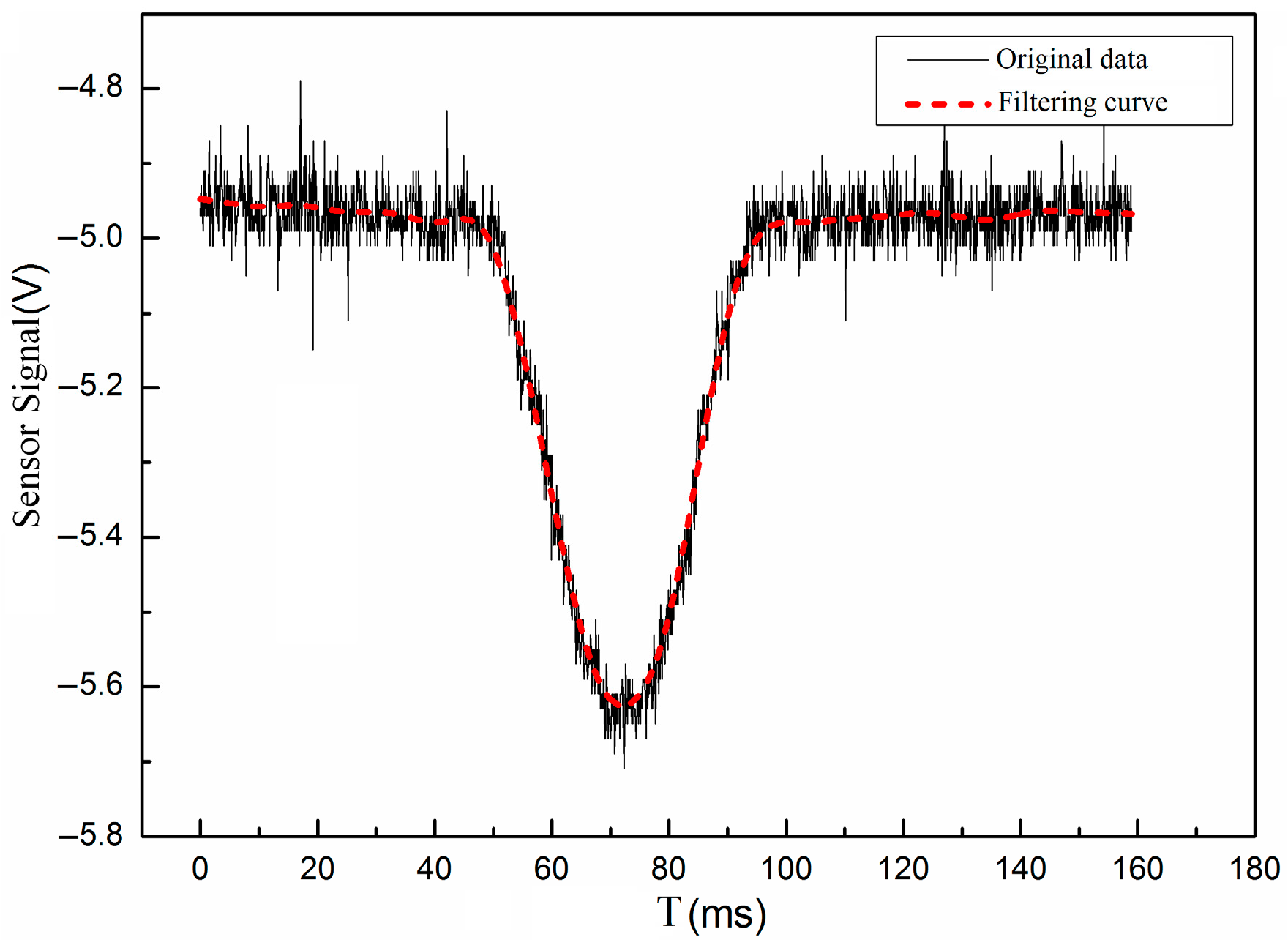
In this research, a Savitzky-Golay smoothing filter is used to filter data. The principle of the Savitzky-Golay smoothing filter is that N data points in the data to be processed are fitted by least squares polynomial of order d. In this paper, 50 data points are selected and fitted by second-order polynomial [20]. The smoothed curve is shown in Figure 2.
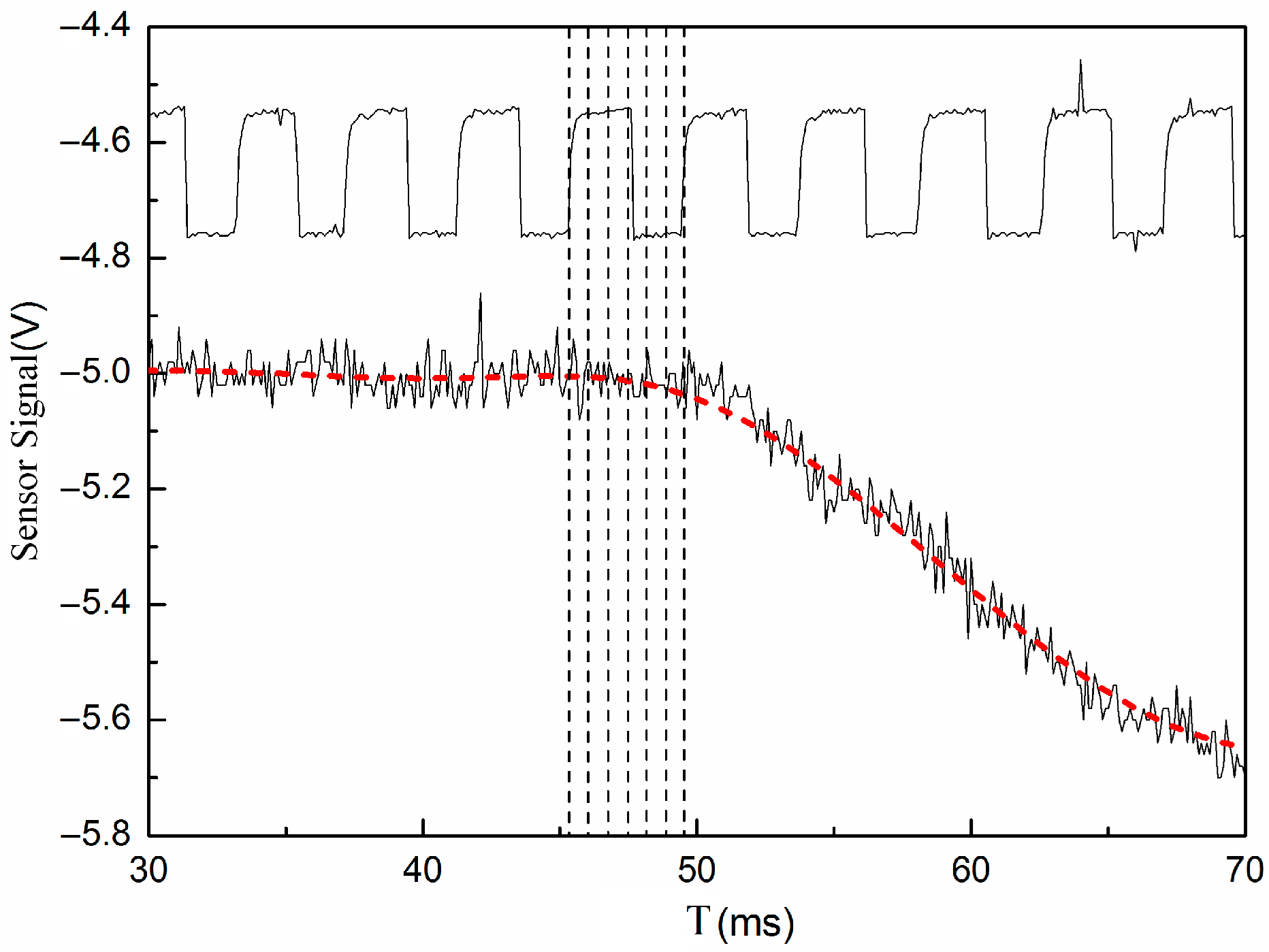
Figure 3 shows the comparison between the speed signal and the lift signal near the valve opening time. The cam speed signal disk is edged with a spaced circumference of sixty teeth, but missing two teeth, with one tooth corresponding to a 6° camshaft rotation angle. If the signal of one tooth is divided into six equal parts, the accuracy of rotation angle in this paper is 1° camshaft rotation angle, that is, 2° CA. The cam’s top dead center position of the test system corresponds to the center position of the tooth’s missing signal.

2.2. Miller Cycle Experimental Device

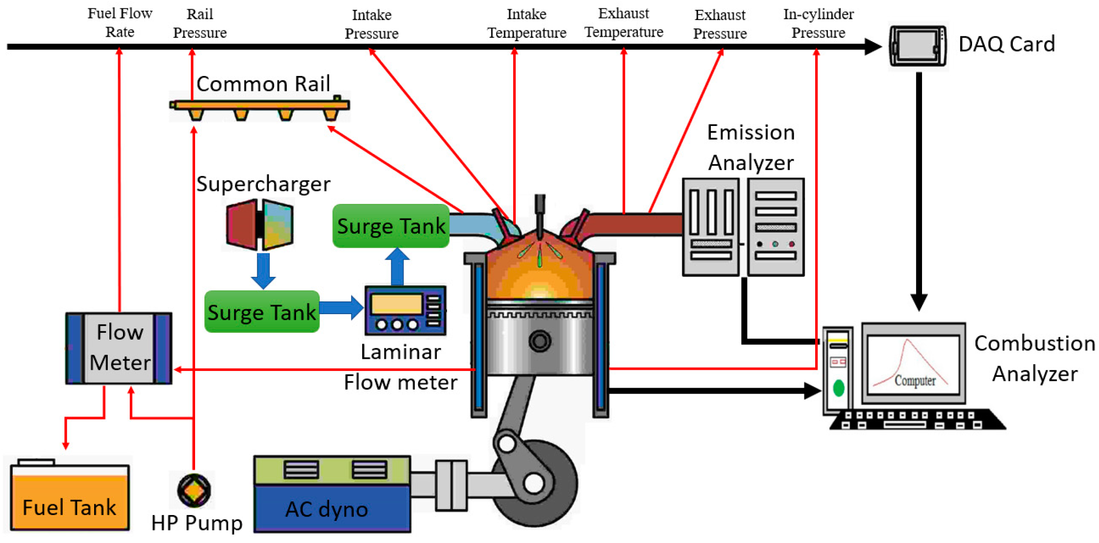
In previous studies [21], the reduction of thermal and friction loads of a single cylinder high power density diesel engine by the Miller cycle was studied. The test platform is shown in the following, as Figure 4. The engine tested is supercharged. Because the realization of the Miller cycle has an effect on the engine intake, the mechanical pressurization method can ensure that the Lambda (excess air coefficient) of the engine is the same under different intake valve phases. In order to avoid the influence of the Miller cycle on the fuel supply system, the common rail fuel injection system is adopted. The engine performance under different inlet valve phases was compared by the engine operating parameters collected by cylinder pressure sensor and combustion analyzer.
The test object is a single cylinder engine. The basic structural parameters of the engine are shown in the Table 1.
By variable valve timing-seeking, the Miller cycle benefits for the engine can be clearly illustrated. For the original valve lift profile of the test engine, the IVC is −110 deg ATDC. Miller camshafts are designed with the same rising profile of the original intake valve and longer holding profile, so that sets the range which can be found in Table 2.

3. Results and Discussion

3.1. Performance of Valve Seating Mechanism

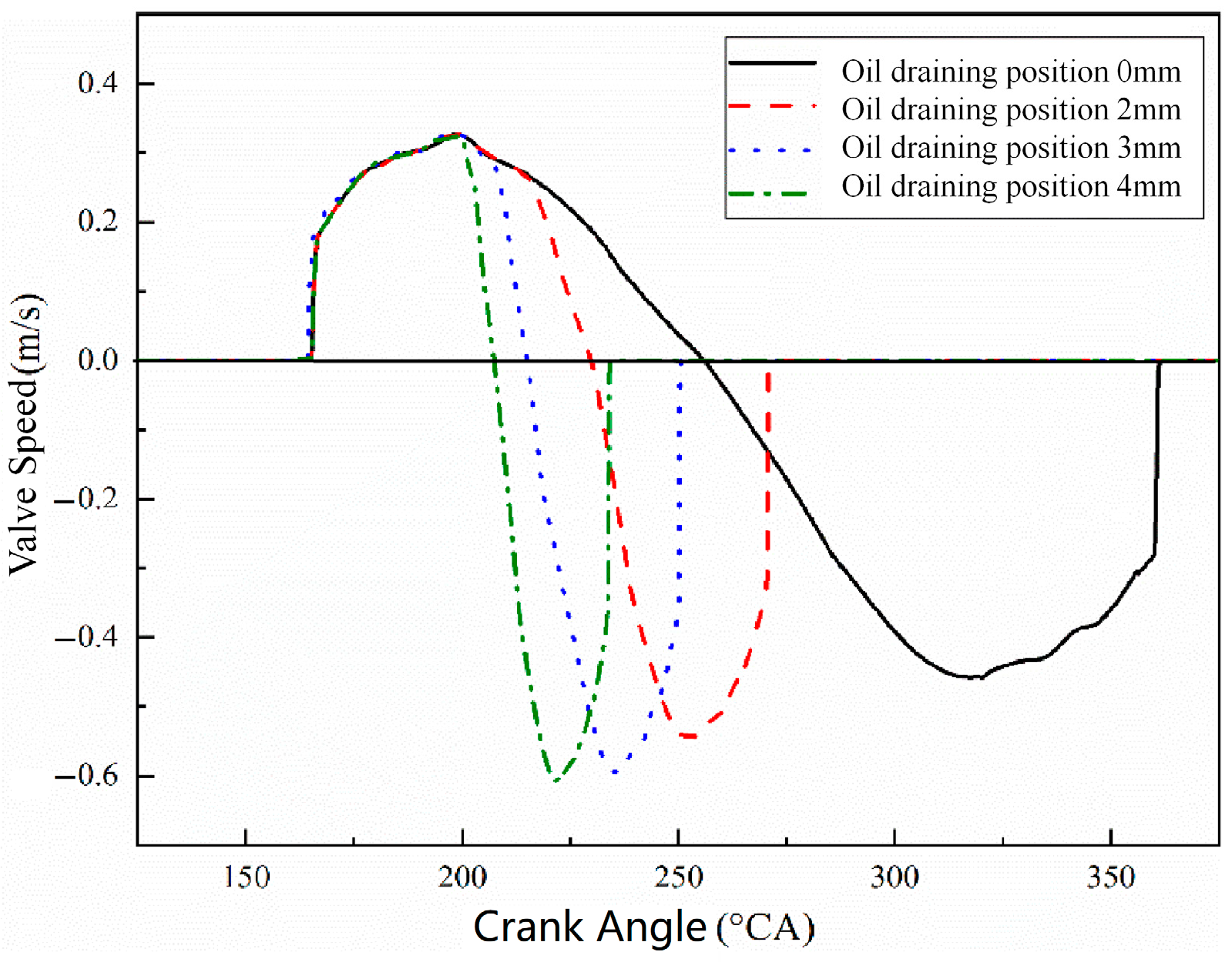
The leakage and compressibility of hydraulic oil in the real system are slightly larger than those in the ideal situation, which makes the acceleration of the valve slower in the process of opening and closing. Nevertheless, since the system is a hydraulic system, there is no cam profile constraint in the process of valve opening and closing, and the impact of the valve is relatively large. In subsequent statements in this section, “oil draining position” refers to the distance from the rising of the plunger to the connecting low-pressure oil port of the chute to the rising of the plunger at the maximum lift of the cam, and “initial plunger position” refers to the distance from the initial position of the plunger top surface to the closed low-pressure oil port. Their selection range is within the limits of the mechanism itself. Figure 5 shows the valve velocity curves with different times of early-releasing oil when at initial plunger position 1 mm and oil draining position of 0, 2, 3 and 4 mm, respectively. It can be seen that the instantaneous speed of valve seating is between 0.3 m/s and 0.4 m/s in each case. According to the relevant standards of AVL and FEV [22,23], the valve seating speed should be less than 0.5 m/s, so the valve seating speed of this mechanism is still within a reasonable range, but it is worse than the original valve seating speed, and valves may be impacted and worn during long-term use.
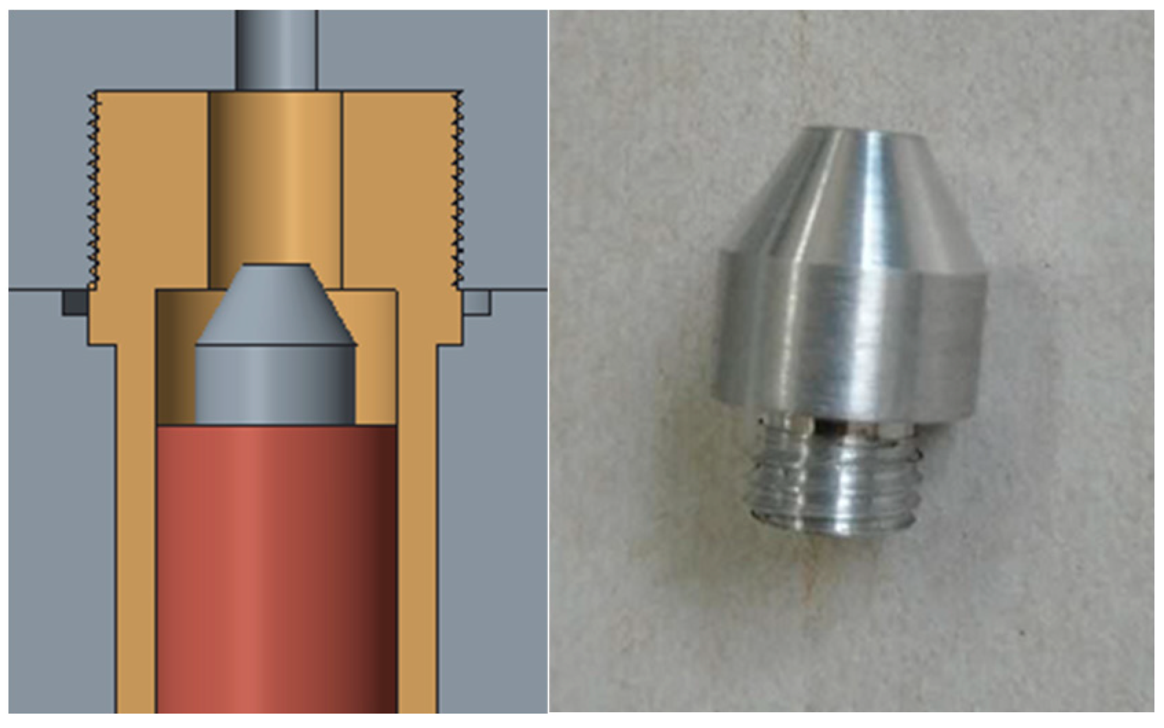
In this paper, the cushioning effect of valve seat is realized by installing a tapered cushion block on the top of the hydraulic piston. The three-dimensional schematic and physical drawings of the seat buffer block are shown in Figure 6. A buffer block reduces the flow area of piston hydraulic oil at the beginning of the valve’s opening and at the end of the valve’s closing. In these two moments, the flow velocity of hydraulic oil decreases, which prolongs the closing time of piston and reduces the moving speed of piston, thereby reducing the impact on the valve seat.
Figure 7 shows the valve lift curve and valve velocity curve under different times of early releasing oil after the valve seat buffer block had been installed. After installing the seat buffer block, the valve slows down significantly during the period of opening and closing. The instantaneous speed of the valve is less than 0.1m/s, and the valve seating impact is diminished.

3.2. Variable Valve Timing and Lift Performance

By using the CD-HFVVS system, the valve timing and lift can be tuned by advancing the time of releasing oil, which will reduce the lift and closing angle of the valve at the same time, while the opening angle of the valve will not change. Figure 8 shows the relationship between valve lift and oil pressure. It can be seen that the lift and closing angle of the valve decreases with the advancing of releasing oil. The feasibility of adjusting the early releasing oil of CD-HFVVS has been verified.
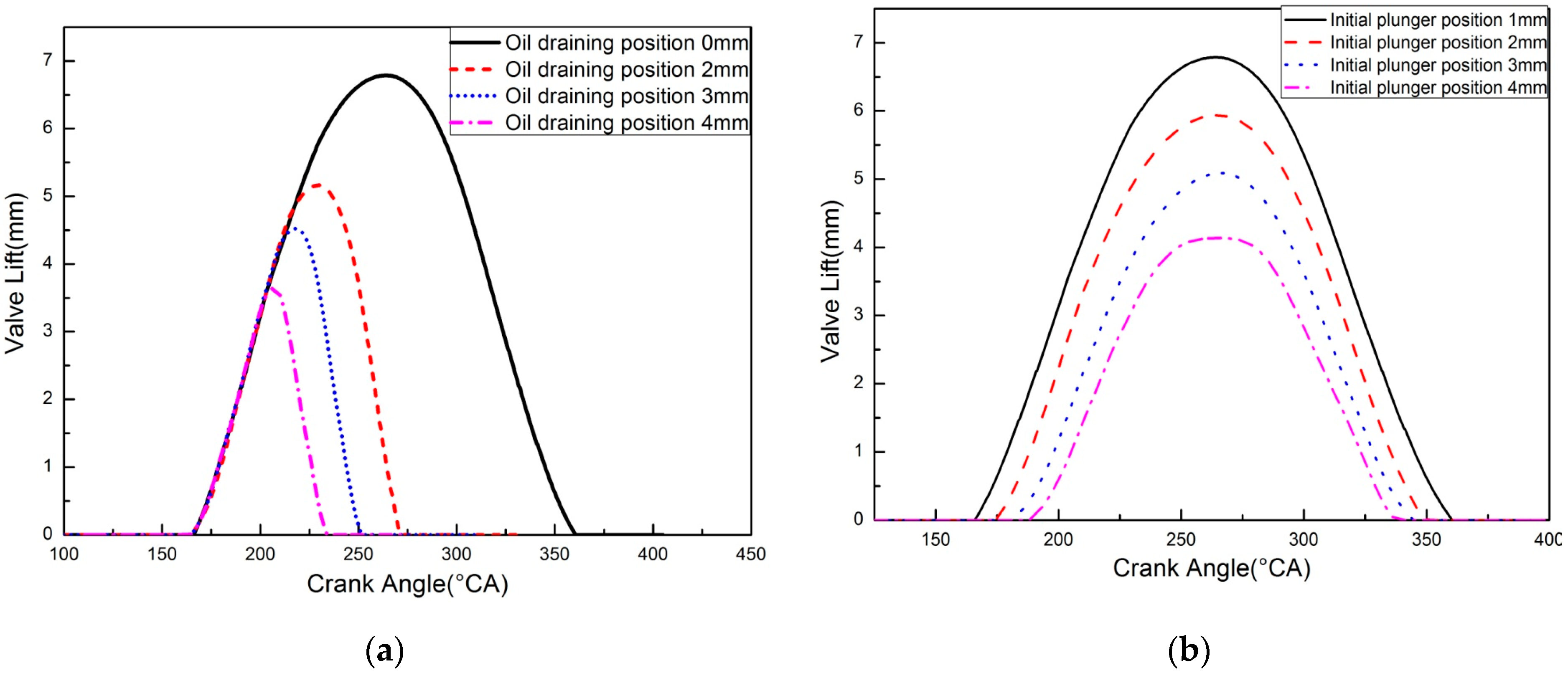
Increasing the initial plunger position will reduce the valve lift, opening angle and closing angle at the same time, and its effect is equivalent to intercepting different cam segments. Figure 9 shows the valve lift curve with initial plunger position of 1 mm and oil draining position of 0, 2, 3 and 4 mm, respectively, and the valve lift curves without early releasing oil and with initial plunger position of 1, 2, 3 and 4 mm, respectively. It can be seen that the valve lift, opening angle and closing angle decrease with the delaying the time of pressuring oil. Therefore, the feasibility of delayed pressure in the oil regulation of CD-HFVVS has also been verified.

3.3. Performance under Different Engine Speed

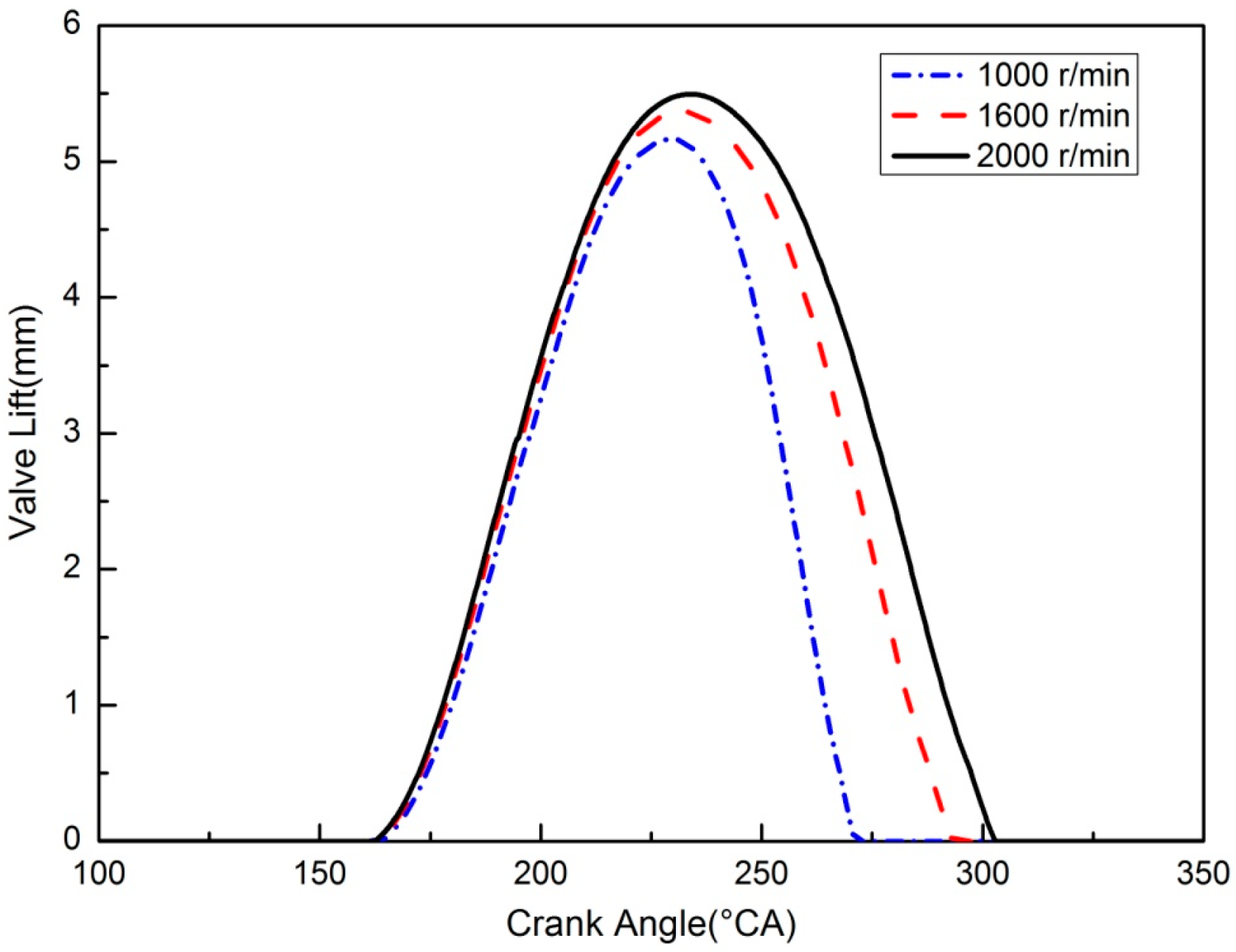
In order to explore the valve motion law of CD-HFVVS under different rotational speeds in actual operation, the comparative tests of different rotational speeds were carried out under the condition of 1 mm initial plunger position and 2 mm oil draining position. Figure 10 shows the valve lift curves at 500, 800 and 1000 rpm, respectively, i.e., engine speeds at 1000, 1600 and 2000 rpm, respectively. As can be seen from the figure, with the increase of rotational speed, the maximum lift and closing angle of the valve will increase to a certain extent, while the opening angle of the valve will be slightly advanced.
The increase of rotational speed will increase the amount of oil pushed by the plunger per unit time. It is necessary for the plunger to rise to a position where the cross-section area of the low-pressure oil port is larger to make the oil release greater than the oil pushed by the plunger, i.e., the “balance oil draining position” will be delayed. In addition, the friction force between fluid and wall increases with the increase of hydraulic oil velocity, the velocity gradient near the wall increases, and the fluid viscous force increases, which also delays the “balance oil draining position”. The delay of the “balance oil draining position” makes the valve continue to descend for a certain distance, thus increasing the lift and the closing angle of the valve. Therefore, in practical application, it is necessary to calibrate the adjusting parameters of the CD-HFVVS according to the rotational speed.

3.4. Performance under Different Oil Temperature

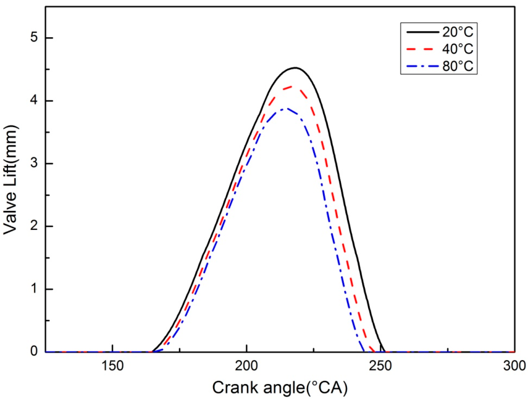
In order to study the influence rule of hydraulic oil temperature, comparative tests of different hydraulic oil temperatures were carried out at 800 rpm idle speed, 1 mm initial plunger position, and 3 mm oil discharge position. The valve lift curves obtained are shown in Figure 11, when the temperature of hydraulic oil is 20, 40, and 80 °C. As can be seen from the figure, with the increase of the temperature of hydraulic oil, the lift and duration of the valve will be significantly reduced, because the increase of temperature will reduce the viscosity of hydraulic oil and increase the leakage of the system. At the same time, the decrease of hydraulic oil viscosity will also advance the “balance oil draining position”, while the “initial plunger position” will be delayed, so the valve lift and duration will decrease with the increase of oil temperature.
The influence of oil temperature is one of the working characteristics of the system, just as is the influence of rotational speed on valve motion. In practical application, the system regulating parameters need to be calibrated according to the rotational speed and oil temperature. The precise control of the valve distribution parameters can be achieved only after the corrected values of the regulating parameters are obtained.

3.5. Miller Performance and Variable Valve Timing

For heavy-duty diesel engines, there are two main benefits of the Miller cycle. First, the Miller cycle can improve efficiency, and secondly, it can effectively reduce the peak pressure.
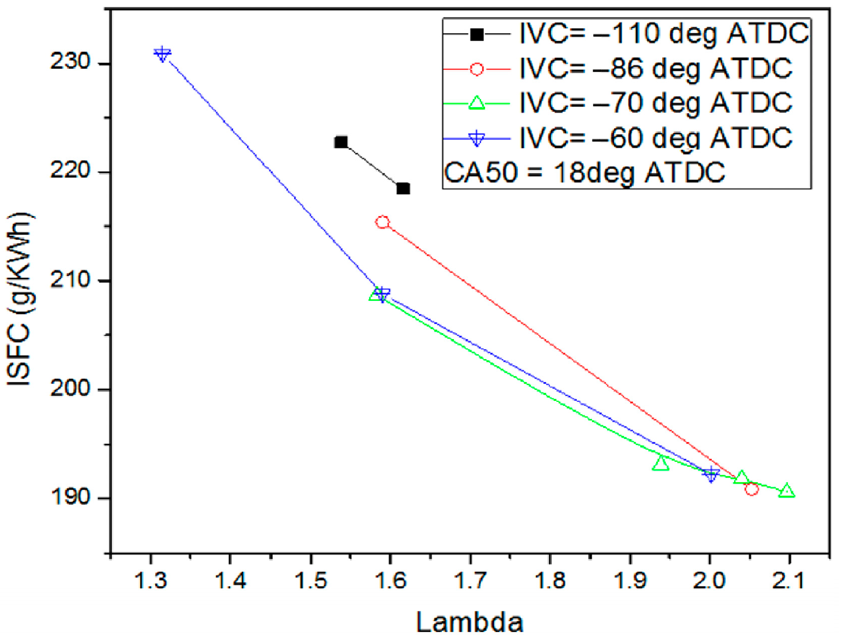
The fuel efficiency or engine efficiency can be promoted under partial load. The test can be found in Figure 12, which shows the relationship between ISFC and Lambda (excess air coefficient) at different inlet late closing angles. It can be seen that under the same condition of Lambda, the fuel consumption can be significantly reduced by properly increasing the late closure range of the intake valve. Similar to the change trend of pressure and temperature, when the late closing angle of intake valve reaches − 70 DEG ATDC, the performance of diesel engine has not changed significantly and ISFC can be reduced for 16 g/kW·h compared with − 110 DEG ATDC. The potential of Miller cycle has then been fully tapped.
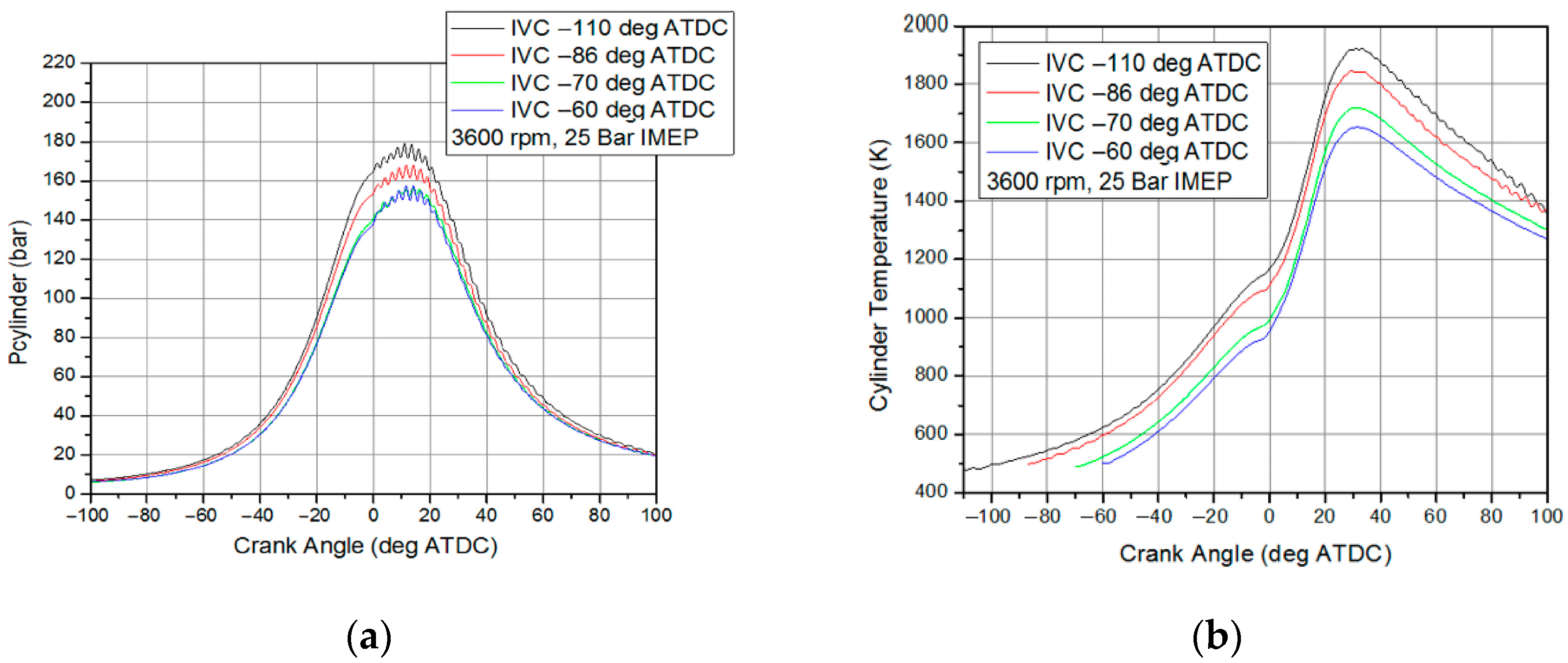
At engine speed of 3600 rpm and load of IMEP 25 bar, the pressure and temperature of the cylinder vary with the intake closure angle, as shown in Figure 13. As can be seen from the figure, the pressure and temperature levels of the cylinder obviously decrease when the late closure range of the intake valve increases. But when the late closing angle of the intake valve reaches − 70 DEG ATDC compared with − 110 DEG ATDC, the decreasing potential of cylinder peak pressure has been saturated. Under these conditions, the maximum pressure and temperature can be reduced for 20 bar and 200 K individually. Continuous increase of the closure angle of the intake valve cannot reduce the peak pressure.
Moreover, the variable lift can enhance the air fuel mixing under partial load [24], which could promote the engine efficiency. In one word, the variable valve timing and lift mechanism are the best methods to implement the Miller cycle and enhance its performance. The new variable valve control system discussed in this paper can effectively improve the cycle performance of the Miller diesel engine.

4. Conclusions

  • The CD-HFVVS changes valve opening angle, closing angle, valve duration and valve lift by changing oil draining position and initial plunger position.
  • A valve seating jerk buffer was tested, which can effectively eliminate valve seating impact.
  • Due to the decrease of the viscosity of hydraulic oil, the oil draining position is advanced and the balance position of pressuring oil is delayed, and the valve lift and duration are reduced.
  • The valve opening duration is prolonged when engine speed increases; this is due to the delay of balance position.
  • By using the mechanism, a single cylinder engine test was performed. The results show that −70 DEG ATDC is the best choice for Miller cycle based on the cylinder pressure performance. Under these conditions, the ISFC can reduce for 16 g/kW·h. and the maximum pressure and temperature can be reduced for 20 bar and 200 K individually.

Author Contributions

Methodology, B.L. (Ben Li); Resources, P.W.; Software, J.Z.; Writing—original draft, F.L.; Writing—review & editing, B.L. (Bolan Liu). All authors have read and agreed to the published version of the manuscript.

Funding

This research received no external funding.

Conflicts of Interest

The authors declare no conflict of interest.

References

  1. Wang, C.; Daniel, R.; Ma, X. Comparison of Gasoline (ULG), 2,5-Dimethylfuran (DMF) and Bio-Ethanol in a DISI Miller Cycle with Late Inlet Valve Closing Time. In Proceedings of the SAE 2012 World Congress & Exhibition, Detroit, MI, USA, 24–26 April 2012. [Google Scholar] [CrossRef]
  2. Luján, J.M.; Bermúdez, V.; Dolz, V.; Monsalve-Serrano, J. An assessment of the real-world driving gaseous emissions from a Euro 6 light-duty diesel vehicle using a portable emissions measurement system (PEMS). Atmos. Environ. 2017, 174, 112–121. [Google Scholar] [CrossRef]
  3. Kovacs, D.; Eilts, P. Potentials of Miller Cycle on HD Diesel Engines Using a 2-Stage Turbocharging System. In Proceedings of the WCX World Congress Experience 2018, Detroit, MI, USA, 10–12 April 2018; SAE Technical Papers: Warrendale, PA, USA, 2018. [Google Scholar] [CrossRef]
  4. Gonca, G. Comparative performance analyses of irreversible OMCE (Otto Miller cycle engine)-DiMCE (Diesel miller cycle engine)-DMCE (Dual Miller cycle engine). Energy 2016, 109, 152–159. [Google Scholar] [CrossRef]
  5. Rinaldini, C.A.; Mattarelli, E.; Golovitchev, V.I. Potential of the Miller cycle on a HSDI diesel automotive engine. Appl. Energy 2013, 112, 102–119. [Google Scholar] [CrossRef]
  6. Flierl, R.; Paulov, M.; Knecht, A.; Hannibal, W. Investigations with a Mechanically Fully Variable Valve Train on a 2.0l Turbo Charged Four Cylinder Engine. In Proceedings of the SAE 2008 World Congress & Exhibition, Detroit, MI, USA, 14–17 April 2008; SAE Technical Papers: Warrendale, PA, USA, 2008. [Google Scholar] [CrossRef]
  7. Gecim, B.; Raghavan, M. Simulation and Test Results for Several Variable-Valve-Actuation Mechanisms. In Proceedings of the SAE 2009 World Congress & Exhibition, Detroit, MI, USA, 20–23 April 2009; SAE Technical Papers: Warrendale, PA, USA, 2009. [Google Scholar] [CrossRef]
  8. Pierik, R.J.; Burkhard, J.F. Design and Development of a Mechanical Variable Valve Actuation System. In Proceedings of the SAE 2000 World Congress, Detroit, MI, USA, 6–9 March 2000; SAE Technical Papers: Warrendale, PA, USA, 2000. [Google Scholar] [CrossRef] [Green Version]
  9. Moriya, Y.; Watanabe, A.; Uda, H.; Kawamura, H.; Yoshioka, M.; Adachi, M. A Newly Developed Intelligent Variable Valve Timing System—Continuously Controlled Cam Phasing as Applied to a New 3 Liter Inline 6 Engine. In Proceedings of the SAE 1996 World Congress & Exhibition, Detroit, MI, USA, 1 February 1996; SAE Technical Papers: Warrendale, PA, USA, 1996. [Google Scholar] [CrossRef]
  10. Nakamura, H.; Nakashima, T.; Aihara, H.; Ookubo, M. Development of Gear Parts for VVT Unit. In Proceedings of the SAE 1997 World Congress & Exhibition, Detroit, MI, USA, 24 February 1997; SAE Technical Papers: Warrendale, PA, USA, 1997. [Google Scholar] [CrossRef]
  11. Minoru, Y. Variable Valve Timing Arrangement for Engine. US6186105B1, 13 February 2001. [Google Scholar]
  12. Hattori, M.; Inoue, T.; Mashiki, Z.; Takenaka, A.; Urushihata, H.; Morino, S.; Inohara, T. Development of Variable Valve Timing System Controlled by Electric Motor. SAE Int. J. Engines 2008, 1, 985–990. [Google Scholar] [CrossRef] [Green Version]
  13. Yonekawa, A.; Ueno, M.; Watanabe, O.; Ishikawa, N. Development of New Gasoline Engine for ACCORD Plug-in Hybrid. In Proceedings of the SAE 2013 World Congress & Exhibition, Detroit, MI, USA, 16–18 April 2013; SAE Technical Papers: Warrendale, PA, USA, 2013. [Google Scholar] [CrossRef]
  14. Hosaka, T.; Hamazaki, M. Development of the Variable Valve Timing and Lift (VTEC) Engine for the Honda NSX. In Proceedings of the Autotechnologies Conference 1991, Monte-Carlo, Monaco, 23–25 January 1991. [Google Scholar] [CrossRef]
  15. Ludwig, B. Less CoD2 Thanks to the Bmw 4-Cyl. In Valvetronic Engine; Associazione Tecnica Dell’Automobile: Turin, Italy, 2002. [Google Scholar]
  16. Luttermann, C.; Schünemann, E.; Klauer, N. Enhanced VALVETRONIC Technology for Meeting SULEV Emission Require-ments. In Proceedings of the SAE 2006 World Congress & Exhibition, Detroit, MI, USA, 3 April 2006; SAE Technical Papers: Warrendale, PA, USA, 2006. [Google Scholar]
  17. Zhen, R.; Zhu, G.G. Modeling and control of an electric variable valve timing system for SI and HCCI combustion mode transition. In Proceedings of the 2011 American Control Conference, San Francisco, CA, USA, 29 June–1 July 2011; IEEE: New York, NY, USA. [Google Scholar]
  18. Kim, J.; Lieu, D.K. A new electromagnetic engine valve actuator with less energy consumption for variable valve timing. J. Mech. Sci. Technol. 2007, 21, 602–606. [Google Scholar] [CrossRef]
  19. Wong, P.; Mok, K. Design and Modeling of a Novel Electromechanical Fully Variable Valve System. In Proceedings of the 2008 SAE International Powertrains, Fuels and Lubricants Congress, Shanghai, China, 23–25 June 2008. [Google Scholar] [CrossRef]
  20. Schulze, H.G.; Foist, R.B.; Ivanov, A.; Turner, R.F.B. Fully Automated High-Performance Signal-to-Noise Ratio Enhancement Based on an Iterative Three-Point Zero-Order Savitzky—Golay Filter. Appl. Spectrosc. 2008, 62, 1160–1166. [Google Scholar] [CrossRef] [PubMed]
  21. Zhang, Y.; Wang, Z.; Bai, H.; Guo, C.; Liu, J.; Li, Y. The Reduction of Mechanical and Thermal Loads in a High-Speed HD Diesel Engine Using Miller Cycle with Late Intake Valve Closing. In Proceedings of the SAE 2017 World Congress & Exhibition, Detroit, MI, USA, 4–6 April 2017; SAE Technical Papers: Warrendale, PA, USA, 2017. [Google Scholar] [CrossRef]
  22. Southam, R.; Reinicke-Murmann, J.; Kreuter, P.; Rogers, G. Analysis of Potential Improvements in Engine Behavior Due to Ceramic Valve Train Components. In Proceedings of the SAE International Congress Exposition 1990, Detroit, MI, USA, 1 February 1990; SAE Technical Papers: Warrendale, PA, USA, 1990. [Google Scholar] [CrossRef]
  23. Çınar, C.; Uyumaz, A.; Polat, S.; Yılmaz, E.; Can, Ö.; Solmaz, H. Combustion and performance characteristics of an HCCI engine utilizing trapped residual gas via reduced valve lift. Appl. Therm. Eng. 2016, 100, 586–594. [Google Scholar] [CrossRef]
  24. Beloiu, D.M. Modeling and Analysis of Valve Train, Part I—Conventional Systems. SAE Int. J. Engines 2010, 3, 850–877. [Google Scholar] [CrossRef]
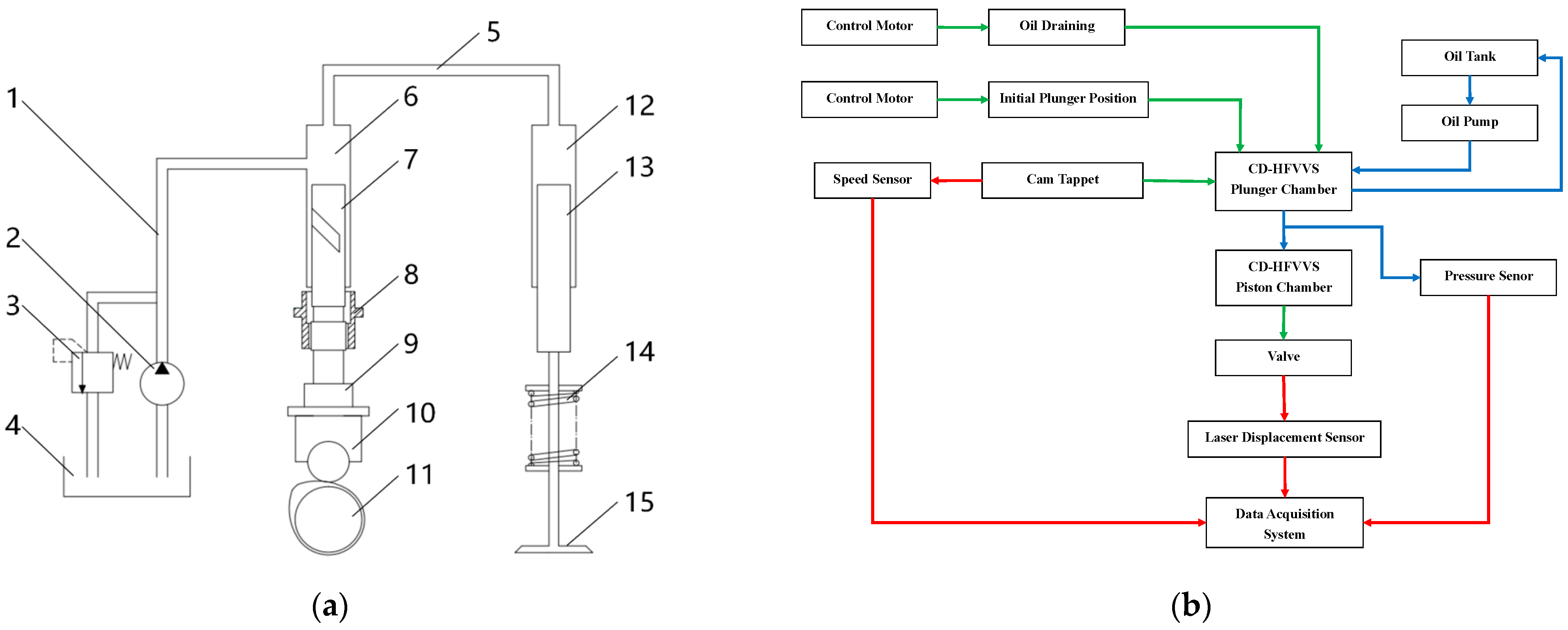
Figure 1. Schematic diagram of valve mechanism experiment, including (a) CD-HFVS mechanism sketch: 1. Low Pressure Oil Ducts, 2. Low Pressure Oil Pump, 3. Relief Valve, 4. Hydraulic Tank, 5. High Pressure Oil Ducts, 6. Plunger Chamber, 7. Plunger, 8. Plunger Rotary Sleeve, 9. Plunger Seat, 10. Tappet, 11. Camshaft, 12. Piston Chamber, 13. Piston, 14. Valve Spring, and 15. Valve; and (b) experimental schematic diagram.
Energies 15 08521 g001
Figure 2. Test curves after smoothing filtering.
Energies 15 08521 g002
Figure 3. Lift and camshaft angle signals near the valve opening time.
Energies 15 08521 g003
Figure 4. High-speed HD diesel engine and the schematic of test setup.
Energies 15 08521 g004
Figure 5. Valve velocity curves with different time of early-releasing oil.
Energies 15 08521 g005
Figure 6. Seat buffer block.
Energies 15 08521 g006
Figure 7. (a) Valve lift curves under different times of early-releasing oil; (b) Valve velocity curve under different times of early-releasing oil.
Energies 15 08521 g007
Figure 8. The relationship between valve lift and oil pressure.
Energies 15 08521 g008
Figure 9. (a) Valve lift curve with different times of early releasing oil; (b) Valve lift curve with different times of delayed pressuring oil.
Energies 15 08521 g009
Figure 10. Valve lift curve at different rotational speeds.
Energies 15 08521 g010
Figure 11. Valve lift curves at different oil temperatures.
Energies 15 08521 g011
Figure 12. Comparison of ISFC with different intake closure angle and Lambda.
Energies 15 08521 g012
Figure 13. (a) Comparison of cylinder pressure with different intake closure angles; (b) Comparison of cylinder temperature with different intake closure angles.
Energies 15 08521 g013
Table 1. Basic engine parameters.
Swept Volume1.05 L
Compression Ratio14.3:1(Geometric)
Combustion ChamberFlat roof/4 valves
Valve TrainDouble Overhead Camshafts
Fuel InjectionCommon Rail
FuelStandard Diesel
Injection Pressure1800 bar
Coolant Temperature80 °C
Table 2. Range of variable valve timing.
Open AngleClosure AngleLift
deg ATDCmm
Intake valve330−110~−70 5~7
Exhaust valve973895~7
Publisher’s Note: MDPI stays neutral with regard to jurisdictional claims in published maps and institutional affiliations.