Abstract
Compared to mechanical compressors, ejector-based refrigeration systems can make direct use of many forms of thermal energy, including waste heat, solar thermal, or biogases. It is known that SE systems have a lower thermal efficiency compared to mechanical compressors because of their lower performance at high compression ratios. In the present work, binary fluid ejector heat pumps with high efficiency are presented based on a proper selection of the binary fluids and the ejector geometry for specific operating conditions of a ground-source heat pump cooling system (GSHP). The existing literature on ejector-based refrigeration systems considers the thermal COP and does not account for many energy losses across the system. In the present paper, the system COP of an ejector-based GSHP that accounts for all energy exchange processes is determined. A method for the calculation of the work done by the boiler feed pump, the refrigeration expansion valve, and the ground loop circulation pump is presented. The influence of the condenser temperature on the entrainment process and the system COP is also discussed. The estimated overall system COP for the three top-ranked binary fluid candidates under various operating conditions was found to range from 1.55 to 3.06.
1. Introduction
In addition to a proper fluid selection, the mixing between the primary and secondary fluids, and thus the entrainment ratio, is one of the most critical parameters that affect the supersonic ejector’s performance [1,2,3,4,5,6,7]. A good understanding of the mixing mechanism, and thus the entrainment, is of high interest for the proper choice of ejector geometry according to the fluids’ properties and the system operating conditions [4,5,8]. A mathematical model predicting the entrainment ratio for supersonic ejectors was recently proposed in [9]. A literature review of ejectors and their applications in refrigeration is found in the literature [10,11].
A survey of the literature shows that the performance of an ejector refrigeration system depends greatly on the ejector geometry [11,12,13,14,15]. The supersonic nozzle geometry [2,16,17,18] and the position of the supersonic nozzle exit [2] strongly affect the flow dynamics (jet expansion, Mach disk, shock waves, etc.) and thus the entrainment ratio and ejector performance. It should be noted that the ejector geometry should be optimized for each set of operating conditions [19,20] and working fluid combination [2,3,4,5].
It is well known that there is a need to improve the ejector performance in order to make ejector-based refrigeration systems economically viable [14,21,22]. It was found that the use of two chemically distinct fluids in the forward and reverse Rankine cycles of an ejector refrigeration system could enhance the thermal COP [1,3,6,10]. El Hassan et al. [3] found that the entrainment ratio, and thus the ejector performance, decreased with an increase in the molecular mass of the primary fluid. However, the entrainment ratio increased with the molecular mass of the secondary fluid.
Buyadgie et al. [23] used zeotropic fluid combinations to investigate their impact on the performance of a BFE refrigeration system (BFE-RS). They found that high molecular weight, low latent heat of evaporation, high normal boiling temperature, and a high compressibility factor of the primary fluid resulted in higher BFE-RS performance. They also confirmed that a refrigerant fluid should have a low molecular weight, high latent heat of evaporation, low boiling point, and a low compressibility factor. Buyadgie et al. [24] found that the BFE-RS has 1.5-times higher efficiency than a single-fluid ejector RS.
Recently, El Hassan [1] developed an algorithm for the selection of high-performance binary fluid pairs for the BFE GSHP cooling application. The author also used numerical simulations in order to understand the entrainment mechanism inside the ejector for different fluid combinations and various operating conditions. It was found that the proper choice of the motive saturation temperature (in the boiler) and the ejector geometry both have a significant impact on the ejector performance for a given fluid pair. The shear forces inside the ejector were stronger when the secondary molecular mass increased, leading to a decrease in the entrainment ratio. In addition, the saturation pressure of the primary fluid strongly affected the momentum of the supersonic jet, the expansion of the jet, and the strength of the shock waves inside the ejector.
Xiao et al. [25] evidenced the importance of the back pressure (ejector exit pressure), and thus the condenser temperature, on the flow development inside supersonic ejectors using numerical simulations. They found both the flow separation from the ejector walls and the development of a secondary shock process inside the ejector. As the back pressure increases, the shock will move upstream into the ejector throat, but the mixing process is not disturbed, and the secondary flow remains choked [25].
Han et al. [26] found a major flow separation (back flow mode) from the ejector walls when the back pressure exceeded a critical value. These authors also found that for a too-small ejector throat, the flow separation resulted from a decrease in the effective area of the secondary flow and an increase in the adverse pressure gradient. Another type of boundary layer separation was observed with a too-large ejector throat diameter due to the absence of shock waves and the resulting upstream propagation of the pressure waves [26].
All existing research studies on the performance of ejector-based refrigeration systems considered the thermal COP as a measure of the overall system performance. In the present paper, the additional energy losses in different parts of the ejector refrigeration system, such as pumps and expansion valves, are considered. The system COP calculation is investigated using a detailed block diagram that illustrates different heat and energy flows across the BFE GSHP cooling system. The present paper describes a method for the system COP calculation that accounts for the work of the boiler feed pump, the refrigeration expansion valve, and the ground loop circulation pump. Such an analysis can be used as a benchmark for future system COP calculations. Finally, the influence of the condenser temperature on the system performance is presented for the BFE GSHP cooling application.
2. Estimation of the Energy Losses in the BFE GSHP Cooling System
Major components of the BFE-based geothermal heat pump cooling system are shown in the block diagram (Figure 1). The operating temperatures, fluids, and air pathways, as well as heat and energy flows, are also shown in Figure 1. The operating temperatures of the studied system were selected according to real GSHP cooling systems used in the United States and Canada [27].
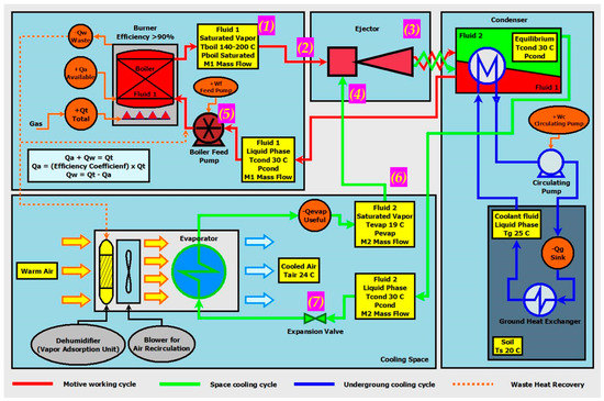
Figure 1.
Schematic of BFE GSHP cooling system in block diagram form.
The main components of the BFE GSHP cooling system are:
- ⮚
- Boiler pressure vessel/gas burner (efficiency > 90%), where the primary (motive) fluid is turned to vapor to drive the ejector, and the boiler feed pump returns primary fluid to the boiler to complete the cycle.
- ⮚
- Binary Fluid Ejector, where the secondary fluid (refrigerant) is entrained and compressed by the primary fluid.
- ⮚
- Cooling space, where the evaporator is employed for air cooling. A vapor chemical adsorption unit could also be installed to improve cooling efficiency. Existing HVAC air blowers and humidifiers may be reused in retrofit situations.
- ⮚
- Condenser with ground loop. Cooling, condensing, and separating the fluid mixture occurs in the condenser, while heat rejection takes place in the underground liquid-based loop (with pump-driven coolant recirculation).
The following color coding is used for cycle identifications: the primary (motive) fluid pathway is red, the secondary (refrigerant) fluid pathway is green, and the ground loop contour is blue. The opportunity for possible waste heat utilization is presented in a dashed amber line (such as pre-heating of the motive fluid and vapor adsorption unit dehumidification).
The system COP accounts for the work done by the boiler feed pump, the refrigeration expansion valve, and the ground loop circulation pump. It can be expressed as follows:
where,
- K1 accounts for the expansion process and the cooling through the expansion valve,
- is the boiler feed pump power,
- Prp is the ground loop circulating pump power,
- and are the enthalpy of vaporization at the evaporator (secondary fluid) and the boiler (primary fluid) temperature,
- and are the average specific heat capacity of the primary fluid (between the boiler and condenser) and the secondary fluid (between the evaporator and condenser),
- and are the mass flow rate of the primary and the secondary fluids,
- TBoil, TEvap, and TCond are the saturation temperature in the Boiler, Evaporator, and Condenser.
Different elements of the system, where work or a heat load is needed, are considered in the system COP estimation as follows:
2.1. Boiler Feed Pump Energy Consumption
A “boiler feed pump” (component (5) in Figure 1) is used to pressurize the primary fluid provided by the condenser and to supply it to the boiler. The primary fluid conditions upstream and downstream from the boiler feed pump are listed below:
- At the pump inlet:
- ○
- The fluid is in a liquid phase with a density .
- ○
- The fluid temperature corresponds to that of the condenser: TCond = 30 °C.
- ○
- The fluid pressure is constant and equal to the condenser pressure PCond.
- ○
- The fluid mass flow rate depends on the ejector’s performance.
- At the pump outlet:
- ○
- The fluid is in a liquid phase and considered incompressible with the same density 1.
- ○
- The fluid temperature corresponds to the boiler temperature TBoil.
- ○
- The fluid pressure is constant and equal to the boiler pressure PBoil.
- ○
- The fluid mass flow rate is .
The boiler-feeding process consists of two steps:
- The fluid is first pressurized adiabatically and injected into the boiler.
- The fluid is then heated isobarically at the boiler pressure PBoil to the boiler temperature TBoil.
The first step corresponds to the work and power needed for the boiler feed pump, while the second step represents the primary fluid heating prior to the saturated vapor generation. It should be mentioned that the second step was considered in the refrigeration cycle COP Equation (1).
The pumping process is considered adiabatic, and the volumetric flow rate () is calculated using the following equation:
= /1; where is the mass flow rate and 1 is the fluid density.
As the fluid is considered non-compressible, the specific volume of the fluid at the pump inlet and outlet remains the same. Thus, the boiler feed pump power for the above volumetric flow rate can be calculated as in Verga et al.’s study [28]:
Using the above equation, the boiler feed pump power was calculated for the binary fluid candidates of the present study. It can be seen that the estimated values are small (Table 1) in comparison to the boiler heat load, which in this case is on the order of several KW.

Table 1.
Boiler feed pump and expansion valve power estimation for different binary fluid candidates.
2.2. Expansion Valve Analysis
An “expansion valve” (component (7) in Figure 1) is used for temperature and pressure drops of the secondary fluid circulating between the condenser and the evaporator. This process is considered isenthalpic; the following fluid conditions are assumed for the process analysis:
- At the expansion valve inlet:
- ○
- The fluid is in liquid phase with density .
- ○
- The fluid temperature is at the condenser temperature TCond = 30 °C.
- ○
- The fluid pressure is constant and equal to the condenser pressure PCond.
- ○
- The fluid mass flow rate is defined by ejector’s efficiency.
- For the fluid coming through the expansion valve:
- ○
- The fluid pressure is changed to the evaporator pressure PEvap.
- ○
- The fluid is in a liquid phase and considered incompressible with the same density 2.
- ○
- The fluid temperature drops due to the expansion work to a temperature TEV.
- ○
- The fluid mass flow rate is .
- At the expansion valve outlet:
- ○
- The fluid pressure remains at the evaporator pressure PEvap.
- ○
- The fluid temperature turns into the evaporator temperature TEvap = 19 °C.
- ○
- In order to achieve the temperature drop, the fluid coming out of the expansion valve is a mixture of liquid and gas phases with respective mass flow rates and .
- ○
- The fluid mass flow rate = + is conserved.
The liquid and gas content of the fluid mixture is analyzed in two steps:
- ⮚
- The fluid is expanded adiabatically and cooled down to a transitional temperature TEV. This corresponds to the estimation of the power needed for the expansion process.
- ⮚
- If TEV is greater than the evaporator temperature (TEvap), then the fluid is cooled down isobarically to the evaporator temperature.
The expansion process is considered adiabatic. As the fluid in a liquid phase is considered non-compressible, its specific volume at the valve inlet and across the valve remains constant. So, the power required for the expansion process is calculated as follows:
where is the volumetric flow rate of the secondary fluid.
The expansion power is calculated for the higher-performance binary fluid candidates shown in Table 1.
The secondary fluid cooling process is analyzed using the following system of equations:
where
- QL represents the heat rejected during the cooling down of the liquid portion,
- CpL is the heat capacity of the liquid phase at the evaporator conditions,
- QG corresponds to the heat rejected during the cooling down of the gas portion,
- CpG is the heat capacity of the gas phase at the evaporator conditions,
- Qph is the heat rejected during the phase change process,
- Hv2 is the enthalpy of vaporization of the secondary fluid at the condenser conditions.
The above system of equations can be reduced to the following expression:
The above equation is used to calculate the mass flow rate needed for the secondary fluid cooling, as shown in Table 1.
2.3. Ground Loop Pump Analysis
Ground-source heat pump systems operate based on heat exchange with the ground: heat sink for the cooling cycle and the heat source for the heating cycle. The GSHP systems are open-loop or closed-loop type. The open-loop system requires direct contact between the circulating fluid and the soil, while a ground heat exchanger (GHX) is used for the closed-loop system. In the present study, a closed-loop GSHP cooling system is investigated. The GHX characteristics are taken from the available literature [29]. Therefore, a GHX vertical configuration with a 25.4 mm diameter U-shape high-density polyethylene tube inserted into a 125 m borehole is considered. The plastic tube is filled with an antifreeze fluid (a mixture of water and glycol), which is continuously circulated by a centrifugal pump. It should be noted that the heat is absorbed on the condenser side and then released to the underground soil. For the GHSP cooling system, the GHX loop should be able to sink a sufficient amount of heat from the condenser to the ground. Hence, the nominal heat load on the condenser side is calculated using the operating conditions shown in Table 1.
The following assumptions are used:
- The heat rejected into the ground is generated by the boiler and the evaporator.
- The boiler heat generation consists of two parts:
- ○
- The primary fluid is preheated to the boiler’s set temperature.
- ○
- The phase change of the preheated fluid occurs, and saturated vapor is produced.
- The heat generated in the evaporator is mainly defined by the phase change process.
For the boiler side:
where
- is the amount of heat required for the primary fluid preheating,
- is the heat capacity at the boiler conditions,
- is the heat load needed for the phase change of the primary fluid,
- is the enthalpy of vaporization of the primary fluid at the boiler conditions.
For the evaporator:
where
- is the heat generated in the evaporator,
- is the enthalpy of vaporization of the secondary fluid at the evaporator conditions.
Therefore, the total heat is:
Table 2 shows the above heat quantities calculated for the selected three fluid pair candidates. is the cooling water flow rate needed for heat rejection with the 5 °C assumption for the ground coil.
Table 2.
Heat load for the condenser and cooling water flow rate for different binary fluid candidates.
The pressure drop and the water flow rate of the cooling ground loop were used to calculate the needed power of the circulating pump. A straight 250 m long plastic pipe (25.4 mm diameter) and a 25 m long stainless-steel pipe (15.9 mm diameter) were used for the pressure drop calculation of the GHX and the condenser coil, respectively. The results are presented in Table 3.
Table 3.
Pressure drop of the ground loop recirculating pump.
The power of the recirculating pump is calculated as follows:
Prp = 284∗1000∗0.53/996.33 = 151 W
Therefore, a power of 151 W is required for the ground loop pump of the BFE GSHP system.
3. System COP Estimation
The final estimation of the system COP is provided below in Table 4. It is based on the operating conditions found in Figure 1, as well as all assumptions relating to, and including the work of, the major system components (expansion valve and pumps), as discussed above. For the present fluid pairs and operating regimes, the overall system COP varies slightly from the refrigeration cycle COP (less than 3%). This confirms a small impact of the additional energy loads on the system COP. Depending on the fluid candidate choice and operating conditions, the highest estimated COP was found to be 3.06.
Table 4.
System COP estimation of the BFE GSHP cooling application.
It should be noted that the most conservative approach was used for the estimation of the equilibrium saturation pressure of the fluid mixture and resulted in the most unfavorable situation for the entrainment mechanism and the system COP. Moreover, an accurate estimation of the equilibrium saturation pressure is not possible using available analytical models. Therefore, additional values for the equilibrium pressure were considered for the CFD modeling in order to account for the interaction between the fluids. Despite the random choice of the additional back pressure values, Table 4 shows that the proper choice of fluid combination can lead to a dramatic increase in the entrainment ratio and the system COP. For example, a COP increase of 113% was observed with the bromotrichloromethane-methanol fluid pair when the compression ratio decreased from 2.27 to 1.55. It should also be noted that the boiler heat load was significantly lower at the smaller CR.
4. Influence of the Condenser Temperature on the System Performance
In this section, one ground source temperature on either side of the nominal temperature (30 °C) is modeled for three binary fluid candidates: difluorodiiodomethane-methanol (CHBrFI-CH3OH), bromofluoroiodomethane-methanol (CF2I2-CH3OH), and bromotrichloromethane-methanol (BrCCl3-CH3OH). The two additional condenser temperatures are 28 °C and 32 °C. The primary pressure was modified in order to account for the variation in the compression ratio for different condenser temperatures. Table 5 shows that the variation in the compression ratio with the condenser temperature depends on the working primary fluid. This variation is slightly different among the three binary fluid candidates since the contribution of the secondary fluid (methanol) to the equilibrium saturation pressure amplitude is significant (at least 70%). It is also seen (Table 5) that the influence of the condenser temperature on the entrainment ratio is strongly dependent on the working fluid pair. For example, a 5.4% increase and a 15.4% decrease in the entrainment ratio were observed for TCond = 28 °C and 32 °C, respectively, with the CHBrFI-CH4O fluid combination, whereas a 20.6% increase (for TCond = 28 °C) and a 19.4% decrease (for TCond = 32 °C) were obtained with the CF2I2-CH4O fluid pair.
Table 5.
Influence of the condenser temperature on the entrainment ratio (TEvap = 19 °C) and COP.
The flow dynamics inside the ejector were analyzed for the CF2I2-CH4O fluid pair for three condenser temperatures of 28, 30, and 32 °C (Figure 2, Figure 3, Figure 4 and Figure 5). Details regarding the CFD method used in the present study were presented in our previous work [1]. The turbulence model used was the SST k-omega () [30]. El Hassan [4] and Bartosiewicz et al. [31] found that the prediction using the SST model provided the best agreement with the experimental results.
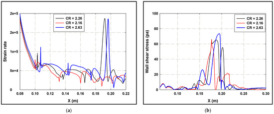
Figure 2.
Shear strain rate profiles (a) and Wall shear stress distribution (b) for the CF2I2-CH3OH fluid pair.
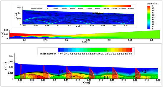
Figure 3.
Flow dynamics inside the ejector at a compression ratio of 2.26 for the CF2I2-CH3OH fluid pair.
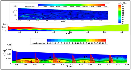
Figure 4.
Flow dynamics inside the ejector at a compression ratio of 2.16 for the CF2I2-CH3OH fluid pair.
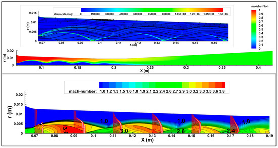
Figure 5.
Flow dynamics inside the ejector at a compression ratio of 2.63 for the CF2I2-CH3OH fluid pair.
It is shown (Figure 2b) that the wall shear stress (WSS) distribution along the ejector wall, particularly in the ejector throat, depended on the studied case. The averaged wall shear stress (integration of the WSS along the ejector wall) presented a 20% decrease at the compression ratio of 2.16 and about an 8% decrease at the compression ratio of 2.63 as compared to the compression ratio of 2.26. Indeed, lower flow momentum and better fluid mixing are observed when the compression ratio decreases. Further optimization of the primary pressure amplitude could be conducted in order to remove the flow separation that occurs upstream from the ejector throat.
The distribution of the shear strain rate (SSR) along the supersonic core boundary (Ma = 1) is presented in Figure 2a. It was shown that the shear strain rate increased with the compression ratio for different ejector sections. This confirmed the presence of stronger shear forces in the jet shear layer when the compression ratio increased. The integration of the shear strain rate along the supersonic core showed an 8.5% decrease in the averaged SSR at the compression ratio of 2.16, and a 5.2% increase at the compression ratio of 2.63 when compared to the compression ratio of 2.26. The strong correlation between the shear forces and the entrainment ratio is of high interest for defining flow control strategies that reduce the shear forces and thus improve the mixing and increase the entrainment ratio. For example, the modulation of the primary jet using non-circular jet nozzles results in the generation of stream-wise vortices. The resulting weak shear forces can lead to the enhancement of both the entrainment ratio and the overall system efficiency.
Figure 3 and Figure 5 show the presence of a near-wall separation region in the mixing chamber at compression ratios of 2.26 and 2.63. Despite the small size of these flow separation regions, their generation should be well understood in order to control them using the appropriate flow control method. For example, the flow separation that occurs for CR = 2.63 is most likely due to shock/boundary layer interaction, which causes a rapid increase in the boundary layer thickness and its shape factor, making the flow more prone to separation. An increase in the back pressure causes the strength of the choke to increase and its location to move upstream, thereby increasing the likelihood and intensity of the flow separation. Large flow recirculation was shown in [32] for reduced primary pressure and in [33] for a two-stage ejector system.
5. Conclusions
The main findings of the present study can be summarized as follows:
- The overall COP of a BFE GSHP system providing space-cooling duty was given for a short list of binary fluid candidates and operating conditions. It was found that the lowest COP of 1.55 corresponds to the highest compression ratio of 2.36, while the highest reported COP of 3.06 is found at the lowest compression ratio of 1.55. It should be noted that the optimization of the ejector geometry based on the binary fluids selected should be further studied; it has the potential to increase the system COP.
- The energy performance of an ejector-based GSHP system can be influenced by three primary factors: the boiler feed pump, the refrigeration expansion valve, and the ground loop circulating pump. The work done by each of these components was calculated in the present paper. It was found that the effect of both the boiler feed pump and the expansion valve on the system COP was small for the fluid pairs and the operating conditions of the present study. On the other hand, it was shown that the energy demand of the ground loop circulation pump, required to maintain a constant differential temperature across the GHX, was around 151 watts. Therefore, the total work was significantly smaller than the available energy in the BFE GSHP cooling system.
- The influence of the condenser temperature on the system COP was studied for two additional saturation temperatures of 28 and 32 °C and for three binary fluid candidates. An increase as high as 21.3% in the system COP was observed for TCond = 28 °C, whereas the strongest decrease was around 33.3% for TCond = 32 °C. The CFD results showed that the condenser temperature variation influenced both the strain rate and the wall shear stress distributions and thus affected the mixing between the two working fluids and the friction losses. In addition, the sensitivity of both the shape and the location of the separation bubble (inside the mixing chamber) to the condenser temperature is also responsible for the entrainment ratio variation. Such mechanisms should be considered for optimization purposes or flow control strategies.
The present study of the BFE GSHP cooling application represents an important first step in realizing such a concept. The presented physical understanding of the flow dynamics inside the ejector for different fluid combinations and operating conditions is of high interest to reach this goal. Further investigations should be conducted for a final choice of the working fluids and the optimization of the ejector geometry. Furthermore, passive and/or active flow control strategies could be used to remove regions of flow separation and improve the mixing between the primary and secondary fluids in order to further enhance the BFE GSHP system COP.
Funding
This research received no external funding.
Data Availability Statement
Data could be provided upon request.
Conflicts of Interest
The author declares no conflict of interest.
Abbreviation
| Acronyms | |
| BFE GSHP | Binary Fluid Ejector Ground Source Heat Pump |
| COP | Coefficient of Performance |
| CFD | Computational Fluid Dynamics |
| CR | Compression Ratio |
| M1 | Molecular mass of the primary fluid |
| M2 | Molecular mass of the secondary fluid |
| Symbols | |
| TBoil | Boiler Saturation Temperature |
| TEvap | Evaporator Saturation Temperature |
| TCond | Condenser Saturation Temperature |
| PBoil | Boiler Saturation Pressure |
| PEvap | Evaporator Saturation Pressure |
| PCond | Condenser Saturation Pressure |
| Enthalpy of vaporization in the Evaporator (secondary fluid) | |
| Enthalpy of vaporization in the Boiler (primary fluid) | |
| Average specific heat capacity of primary fluid | |
| Average specific heat capacity of secondary fluid | |
| Mass entrainment ratio | |
| Boiler feed pump power | |
| Volume flow rate through the boiler feed pump | |
| Mass flow rate through the boiler feed pump | |
| Mass flow rate of liquid exiting the expansion valve | |
| Mass flow rate of gas exiting the expansion valve | |
| = | |
| Density of the liquid flowing through the boiler feed pump | |
| Ground loop circulating pump power | |
| CPL | Heat capacity of the liquid phase at the evaporator conditions |
| Heat capacity of the gas phase at the evaporator conditions | |
| Heat capacity at the boiler conditions | |
| Amount of heat required for the primary fluid preheating | |
| Heat load needed for the phase change of the primary fluid | |
| Amount of heat generated in the evaporator | |
References
- El Hassan, M. Numerical Characterization of the Flow Dynamics and COP Estimation of a Binary Fluid Ejector ground Source Heat Pump Cooling System. Fluids 2022, 7, 250. [Google Scholar] [CrossRef]
- El Zohbi, B.; Bukharin, N.; Assoum, H.H.; Abed-Meraim, K.; Sakout, A.; El Hassan, M. Investigation of the effects of the jet nozzle geometry and location on the performance of supersonic fluid ejectors. Energy Rep. 2022, 8, 228–233. [Google Scholar] [CrossRef]
- El Hassan, M.; Assoum, H.H.; Bukharin, N.; Abed-Meraim, K.; Sakout, A. Investigation of thermo-physical fluid properties effect on binary fluid ejector performance. Energy Rep. 2020, 6, 287–292. [Google Scholar] [CrossRef]
- El Hassan, M. Numerical Investigation of the Flow Dynamics inside Supersonic Fluid Ejector. Arab. J. Sci. Eng. 2019, 45, 909–919. [Google Scholar] [CrossRef]
- El Hassan, M.; Gubanov, A.; May, W.; Martinuzzi, R. Numerical investigation of the flow dynamics of a supersonic fluid ejector. In Proceedings of the International Conference on Heat Transfer and Fluid Flow, Prague, Czech Republic, 11–12 August 2014. [Google Scholar]
- Buyadgie, O.; Drakhnia, O.; Miyazaki, T. The analysis of binary fluid ejector assisted solar desalination system. In Proceedings of the 17th International Refrigeration and Air Conditioning Conference, West Lafayette, IN, USA, 9–12 July 2018. [Google Scholar]
- Ameur, K.; Aidoun, Z. Nozzle Displacement Effects on Two-Phase Ejector Performance: An Experimental Study. J. Appl. Fluid Mech. 2018, 11, 817–823. [Google Scholar] [CrossRef]
- Wen, C.; Rogie, B.; Kærn, M.R.; Rothuizen, E. A first study of the potential of integrating an ejector in hydrogen fueling stations for fuelling high pressure hydrogen vehicles. Appl. Energy 2020, 260, 113958. [Google Scholar] [CrossRef]
- Friso, D. Mathematical Modelling of the Entrainment Ratio of High Performance Supersonic Industrial Ejectors. Processes 2022, 10, 88. [Google Scholar] [CrossRef]
- Sun, D.W.; Eames, I.W. Recent development in the design theories and applications of ejectors—A review. J. Inst. Energy 1995, 68, 65–79. [Google Scholar]
- Chunnanond, K.; Aphornratana, S. Ejectors: Applications in refrigeration technology. Renew. Sustain. Energy Rev. 2004, 8, 129–155. [Google Scholar] [CrossRef]
- Eames, I.W.; Aphornratana, S.; Haider, H. A theoretical and experimental study of a small-scale steam jet refrigerator. Int. J. Refrig. 1995, 18, 378–386. [Google Scholar] [CrossRef]
- Eames, I.W. A new prescription for the design of supersonic jet pumps: The constant rate of momentum change method. Appl. Therm. Eng. 2002, 22, 121–131. [Google Scholar] [CrossRef]
- Chunnanond, K.; Aphornratana, S. An Experimental investigation of a steam ejector refrigerator: The analysis of the pressure profile along the ejector. Appl. Therm. Eng. 2004, 27, 311–322. [Google Scholar] [CrossRef]
- Smierciew, K.; Gagan, J.; Butrymowicz, D. Application of numerical modelling for design and improvement of performance of gas ejector. Appl. Therm. Eng. 2019, 149, 85–93. [Google Scholar] [CrossRef]
- Surya, S.D.; Vasu, T.A.; Raghavan, K.S.; Murthy, C. CFD simulation of ejector in steam jet refrigeration. J. Appl. Mech. Eng. 2017, 6, 263. [Google Scholar] [CrossRef]
- Ruangtrakoon, N.; Thongtip, T.; Aphornratana, S.; Sriveerakul, T. CFD simulation on the effect of primary nozzle geometries for a steam ejector in refrigeration cycle. Int. J. Therm. Sci. 2013, 63, 133–145. [Google Scholar] [CrossRef]
- Thongtip, T.; Aphornratana, S. An experimental analysis of the impact of primary nozzle geometries on the ejector performance used in R141b ejector refrigerator. Appl. Therm. Eng. 2017, 110, 89–101. [Google Scholar] [CrossRef]
- Poirier, M.; Giguère, D.; Sapoundjiev, H. Experimental parametric investigation of vapor ejector for refrigeration applications. Energy 2018, 162, 1287–1300. [Google Scholar] [CrossRef]
- Ramesh, A.S.; Sekhar, S.J. Experimental and numerical investigations on the effect of suction chamber angle and nozzle exit position of a steam-jet ejector. Energy 2018, 164, 1097–1113. [Google Scholar] [CrossRef]
- Eames, I.W.; Ablwaifa, A.E.; Petrenko, V. Results of an experimental study of an advanced jet-pump refrigerator operating with R245fa. Appl. Therm. Eng. 2007, 27, 2833–2840. [Google Scholar] [CrossRef]
- Sankarlal, T.; Mani, A. Experimental investigations on ejector refrigeration system with ammonia. Renew. Energy 2007, 32, 1403–1413. [Google Scholar] [CrossRef]
- Buyadgie, D.I.; Nichenko, S.V.; Buyadgie, O.D. Novel ejector cooling technologies using binary fluids. In Proceedings of the 9th International Conference on Sustainable Energy Technologies, Shanghai, China, 24–27 August 2010. [Google Scholar]
- Buyadgie, D.; Buyadgie, O.; Artemenko, S.V.; Chamchine, A.; Drakhnia, O. Conceptual design of binary/multicomponent fluid ejector refrigeration systems. Int. J. Low-Carbon Technol. 2012, 7, 120–127. [Google Scholar] [CrossRef]
- Xiao, J.; Wu, Q.; Chen, L.; Ke, W.; Wu, C.; Yang, X.; Yu, L.; Jiang, H. Assessment of Different CFD Modeling and Solving Approaches for a Supersonic Steam Ejector Simulation. Atmosphere 2022, 13, 144. [Google Scholar] [CrossRef]
- Han, Y.; Wang, X.; Sun, H.; Zhang, G.; Guo, L.; Tu, J. CFD simulation on the boundary layer separation in the steam ejector and its influence on the pumping performance. Energy 2019, 167, 469–483. [Google Scholar] [CrossRef]
- Liu, X.; Munk, J. Field Test and Evaluation of Residential ground Source Heat Pump Systems Using Emerging ground Coupling Technologies. In Proceedings of the 11th International Energy Agency Heat Pump Conference, Montréal, QC, Canada, 11–12 May 2014. [Google Scholar]
- Varga, S.; Lebre, P.S.; Oliveira, A.C. Readdressing working fluid selection with a view to designing a variable geometry ejector. Int. J. Low-Carbon Technol. 2015, 10, 205–215. [Google Scholar] [CrossRef]
- RETScreen International Clean Energy Decision Support Centre. “Clean Energy Project Analysis: Retscreen Engineering & Cases Textbook, Ground-Source Heat Pump Project Analysis Chapter” Minister of Natural Resources Canada 2001–2005. 2005. Available online: http://www.alternativesynergy.org/SEDV-work/Project/RETScreen/Textbook_Intro.pdf (accessed on 1 October 2022).
- Menter, F.R. Two-equation eddy viscosity turbulence models for engineering applications. AIAA J. 1994, 32, 1598–1605. [Google Scholar] [CrossRef]
- Bartosiewicz, Y.; Aidoun, Z.; Desevaux, P.; Mercadier, Y. Numerical and experimental investigations on supersonic ejectors. Int. J. Heat Fluid Flow 2005, 26, 56–70. [Google Scholar] [CrossRef]
- Hanafi, A.S.; Mostafa, G.M.; Waheeda, A.; Fathya, A. 1-D Mathematical Modeling and CFD Investigation on Supersonic Steam Ejector in MED-TVC. In Proceedings of the 7th International Conference on Applied Energy—ICAE 2015, Abu Dhabi, United Arab Emirates, 28–31 March 2015. [Google Scholar]
- Kong, F.; Kim, H.D. Analytical and computational studies on the performance of a two-stage ejector–diffuser system. Int. J. Heat Mass Transf. 2015, 85, 71–87. [Google Scholar] [CrossRef]
Publisher’s Note: MDPI stays neutral with regard to jurisdictional claims in published maps and institutional affiliations. |
© 2022 by the author. Licensee MDPI, Basel, Switzerland. This article is an open access article distributed under the terms and conditions of the Creative Commons Attribution (CC BY) license (https://creativecommons.org/licenses/by/4.0/).