Article

Slope Stability Numerical Analysis and Landslide Prevention of Coal Mine Waste Dump under the Impact of Rainfall—A Case Study of Janina Mine, Poland

by
Phu Minh Vuong Nguyen
1,*,
Aleksander Wrana
1,
Sylwester Rajwa
1,
Zenon Różański
2 and
Robert Frączek
3
1
Department of Extraction Technologies, Rockburst and Risk Assessment—BG, Central Mining Institute, 1 Gwarków Sq., 40-166 Katowice, Poland
2
Faculty of Mining, Safety Engineering and Industrial Automation, Silesian University of Technology, 2a Akademicka st., 44-100 Gliwice, Poland
3
Geology Department, TAURON Wydobycie S.A., 37 Grunwaldzka st., 43-600 Jaworzno, Poland
*
Author to whom correspondence should be addressed.
Energies 2022, 15(21), 8311; https://doi.org/10.3390/en15218311
Submission received: 29 August 2022 / Revised: 28 September 2022 / Accepted: 2 November 2022 / Published: 7 November 2022
(This article belongs to the Special Issue Coal Mining)

Abstract

:
In Poland, the mining waste from underground coal mines is commonly deposited in surface dump sites, forming slopes or piles of materials dozens of meters high. Because of the loose structure of a mine waste dump slope, landslides may occur after a heavy rainfall. This requires significant labor costs in reforming the mine waste dump sites and disturbs the continuity of the depositing operations. Moreover, if the mine waste dump sites located in the built-up areas, such as in the Janina mine waste dump, landslides apparently can threaten even lives and properties. Therefore, a mine waste dump stability analysis is necessary for ensuring safety. In this paper, slope stability analysis was conducted using numerical modeling under the impact of rainfall for the Janina mine waste dump, located in Libiąż, Poland. The results indicated that slope tends to loose stability in case of high rainfall intensity and short duration. Then, slope reinforcement using soil nailing and steel mesh was proposed to prevent landslide under the impact of high rainfall intensity. Once again, slope stability analysis was carried out with selected reinforcement. Meanwhile, slope monitoring was performed to assess the slope reinforcement implementation at the Janina mine waste dumps against the impact of high rainfall intensity. Based on the modeling and monitoring outcomes, assessments of slope stability and selected landslide prevention measures for the Janina mine waste dump under the impact of rainfall were presented.

1. Introduction

In general, one of the most important factors causing the instability of a slope is the increase in water content, which reduces the shear strength of slope materials. Then, the potential landslides can be mobilized during an intensive rainfall. The extremely wet conditions caused widespread slope failures in both natural and constructed slopes worldwide: Brazil [1], Indonesia [2], Turkey [3], the USA [4], Italy [5], Japan [6], France [7], and Nicaragua [8]. The mentioned landslide cases are a clear evidence indicating the significant impact of rainfall on slope stability.
In case of mine waste dump, the potential landslide trigged by rainfall was obviously higher due to the loose and porous structure of dump slopes. The mining waste is usually stored in the form of a slope or a pile. Over time, these mine waste dumps become larger and higher due to the limit of available land areas for depositing. The stability of these mine waste dumps has been a major concern to mine site management over the years [9,10,11,12,13,14,15]. Improper design of a mine waste dump may lead to potential landslides that entails incalculable costs, including loss of human lives, local infrastructure and environment [16,17,18,19,20,21,22,23]. Therefore, it is necessary to carry out more research on the slope stability of mine waste dumps affected by rainfall. Due to the different characteristics of mining waste and depositing methods, any case of mine waste dump should be analyzed individually.
In Poland, coal mine waste dumps mostly contain multi-grain sizes of claystones, mudstones, sandstones, conglomerates, carbonates, carbonaceous shales, and pyrite-bearing carbonaceous rocks [24,25,26]. The Janina coal mine commenced construction operations related to depositing its mining waste on the slopes in mid-2006. In the period August–November 2016, movement of the mine waste dump slope was observed in the north-western part, i.e., an approximately 300 m section of ditches has been moved away relative to the designed boundaries to the built-up areas at Dąbrowski street (Figure 1). As an element of landslide prevention, depositing operation has been stopped. In general, the geodetic measurements showed that the slope movement process has been completely slowed down. However, the increase in displacements of slope has been observed at some measuring points, where the rainfall and snowmelt water migration in the subsurface layers occurred. The effects on the slope surface started to be visible in 2017 (Figure 2).
The main goal of this research is to determine the impact of rainfall on the Janina mine waste dump slope. As a result, landslide prevention measures will be proposed to ensure safety for local people and infrastructure around the Janina mine waste dump slope. For this purpose, a numerical analysis of slope stability was conducted taking the possible impact of rainfall into account. In the next step, a slope reinforcement using soil nailing with steel mesh and an anti-erosion geogrid along with humus soil and grass seeding was proposed, aiming to prevent the potential landslides triggered by high rainfall intensity at the Janina mine waste dump. Numerical analysis using the finite difference method code—FLAC2D [27], presenting the exact geo-mining conditions of the Janina mine waste dump and slope monitoring using photogrammetric technique with a drone were employed to evaluate the slope stability and slope reinforcement implementation at the Janina mine waste dump with various rainfall scenarios. Based on the final results, assessments of slope stability and slope reinforcement implementation at the Janina mine waste dump under the impact of rainfall were presented. The outcome is expected to provide references for other cases of mine waste dump in Poland.

2. Overview of Stability Analysis of Mine Waste Dumps in Term of Rainfall Impact

Research has been carried out to determine the rainfall impact on slope stability of mine waste dump and, consequently, to prevent potential slope failure during high rainfall intensity, if necessary. A brief summary of case studies is drawn in Table 1.
Some important notes can be drawn as follows:
-
It should be noted that the numerical approach was applied for all studies. It seems to be obvious due to the rapid development of computer science. The biggest advantage of numerical modeling is to enable illustrating precisely the interaction of analyzed structures with a number of influencing factors as input data, which is impossible in analytical and/or empirical analyses. The results of numerical calculations are various and especially useful when coupled with the results of laboratory tests and in situ tests;
-
Although the significant impact of high rainfall intensity on the mine waste dump slope was pointed out, landslide prevention measures have not been applied and examined in most cases.

3. Case Study

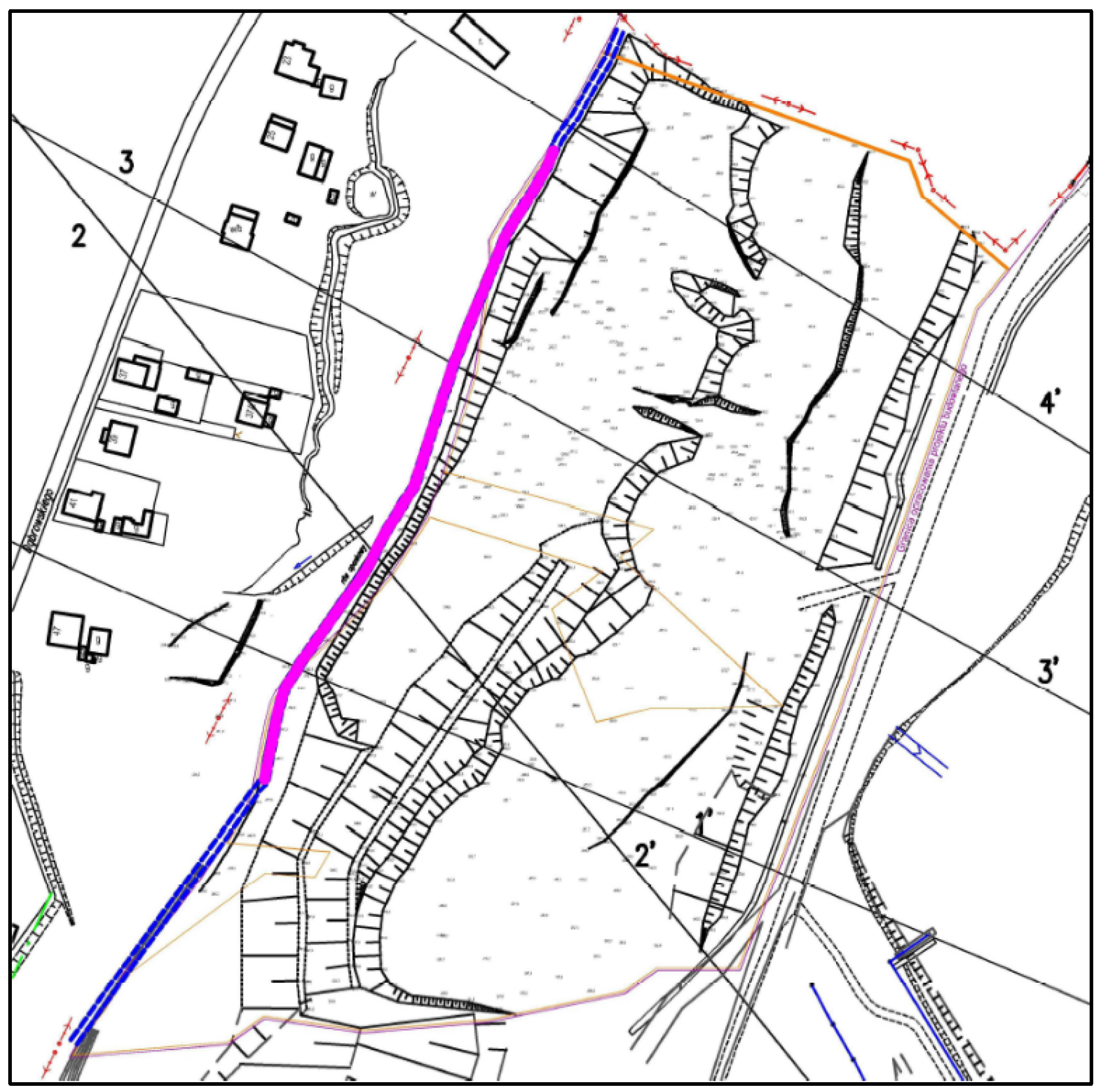
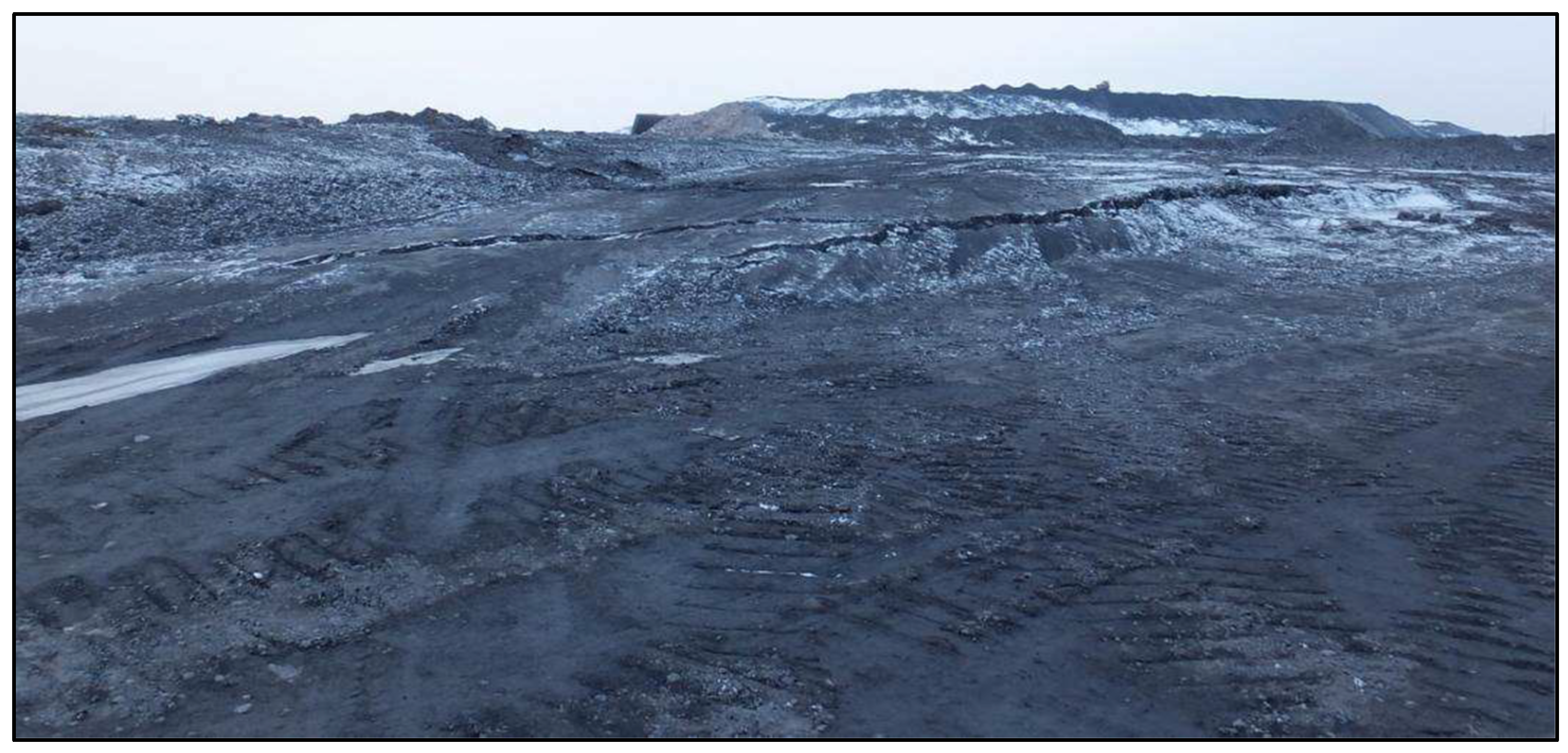
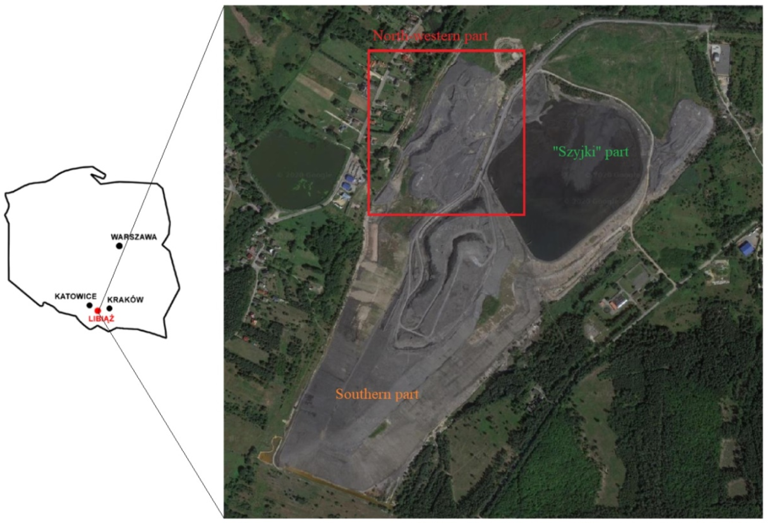
3.1. General Characteristics of the Janina Mine Waste Dump

In terms of geography, the Janina mine waste dump is located in the area of Krakowska st. in the southern part of Libiąż town, Chrzanowski county, Lesser Poland Voivodeship, approximately 350 km south-west of the capital, Warsaw. The mine waste dump area is divided into three parts, i.e., the active southern part, the Szyjki tailings part, and the north-western part. The studied site is located between the west of Dąbrowskiego st. and the east of the Szyjki tailings (Figure 3). The dump has a surface area of 33.51 ha and a storage capacity of approximately 8 million m3 (~13 million Mg). Waste material from the mechanical coal processing plant contains 33% coarse grains and 67% fine grains and, separately, contained sand (28.5%), silt (22.5%), and clay (16%). The general slopes of the Janina mine waste dump have a slight inclination, not exceeding 30°. Intensive rainwater runoff along the fall line was observed due to the lack of an proper drainage system [37,38].

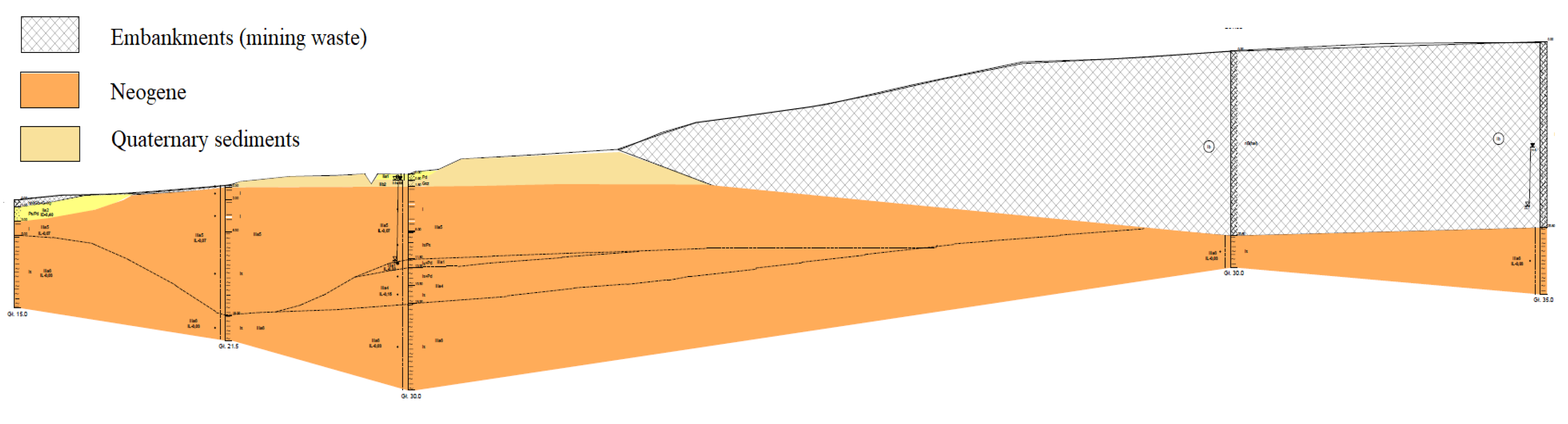
3.2. Brief Characteristics of Geological, Hydrogeological and Geotechnical Conditions at the Studied Site

The geological structure of the studied site is built of Triassic formations (subsoil) and Neogene and Quaternary formations in the overburden. The Neogene consists of clays with interfacing or laminations of sands, marls or dusts. These formations constitute an impermeable complex for the Quaternary aquifer. Their thickness is approximately 90.0 m. The Quaternary consists of sands and clays. The thickness of the Quaternary formations ranges from approximately 3.0 m to a dozen meters. Above, there are Quaternary anthropogenic sediments in the form of non-construction embankments with a varied lithological composition. They are formed by soils made of medium-grained sands mixed with sandy loams and post-mining materials [38].
Basically, the following aquifers were identified within the studied area [38]:
-
Quaternary aquifer is associated with permeable sandy formations, which lie on the impermeable formations of the older substrate. The groundwater occurs in fine-grained sands and is supplied by rainfall infiltration into the substrate and remains in a hydraulic relationship with the waters of a nearby pond and the waters of the Vistula River. The non-construction embankments within the studied area can be classified as medium-permeable soils, and their permeability will depend on the amount of cohesive soil admixtures in their composition. Cohesive formations in the form of sandy loams, silty loams and loam can be classified as impermeable soils with a water permeability coefficient k of 10−6 ÷ 10−8 cm/s. On the other hand, loose deposits formed in the form of fine-grained and medium-grained sands with clay admixtures. They can be classified as permeable with a water permeability coefficient k of 10−3 ÷ 10−5 cm/s;
-
The Triassic aquifer is associated with fractured and caverned limestones and dolomites of mussel limestone and rite in which fissure-karst aquifers are found, as well as subordinate sandstones, where the fissure-pore aquifers are located. The water-bearing complex of the carbonate series, including the tied deposits of shell limestone and rash on the northern side of Libiąż, is a part of the Main Underground Water Reservoir with an area of approximately 310 km2. The reservoir is supplied mainly as a result of direct infiltration of precipitation—in the outcrop zone or indirectly from the Quaternary aquifer, in the areas where the watered formations of the Quaternary lie directly on the Triassic formation;
-
The aquifers within the Carboniferous are mainly permeable compositions (sandstones) of the Libiąż and Laziska strata (Krakow sandstone series) characterized by good water-bearing parameters. The sandstone layers are characterized by different granulation and thus effective porosity. The effective porosity of sandstones is on average 18.0% in the Libiąż strata and 14.8% in the Laziska strata. Thickness of sandstone layers exceed several dozen meters, separated by coal and clay beds. Carboniferous horizons are supplied in outcrops, as well as through Triassic and Quaternary formations in places where there are no insulating impermeable deposits (including Miocene clay layers), or their continuity is interrupted by mountain formation deformations.
In the studied area, there are Quaternary anthropogenic sediments, embankment soils included in series I, the native Quaternary sediments represented by glacial formations included in series II, and sediments of the older Neogene subsoil, which were included in the geotechnical series III (Figure 4).
Geotechnical properties of each material series can be found in the Table 2.

3.3. Rainfall in the Janina Mine Waste Dump Region

The area average of annual total precipitation in Poland In 2021 and 2020 was 645.4 mm and 627.4 mm, respectively, which are higher than the norm based on measurements in the years 1991–2020 [39]. According to data base collected by The Institute of Environmental Protection—National Research Institute, annual total precipitation tends to go higher over time and is predicted to reach 800 mm in next decades [40].
In Chrzanowski county, the average annual amount of precipitation is predicted to reach 900 mm to 2050. Maximum precipitation occurs in three months: May, June and July with the monthly value of approximately 100 mm (Figure 5).

4. Numerical Analysis of Slope Stability of the Janina Mine Waste Dump under the Impact of Rainfall

4.1. Modeling Approach

The two-phase flow option in FLAC2D allows numerical modeling of the flow of two immiscible fluids through porous media. In two-phase flow, the void space is completely filled by the two fluids. One of the fluids (the wetting fluid) wets the porous medium more than the other (the non-wetting fluid). As a result, the pressure in the non-wetting fluid will be higher than the pressure in the wetting fluid. The pressure difference is the capillary pressure, which is a function of saturation [27].
The presence of capillary pressure in unsaturated soils can have a significant impact on the stability of a slope. Unconfined groundwater in soil is usually characterized by the occurrence of a capillary zone in which the soil is not fully saturated. A common assumption in the study of fluid flow in unconfined aquifers is that air is at constant atmospheric pressure in the void space; water is then the only fluid of concern in the formulation [27].
To account for capillarity, the two-phase flow logic based on an extended form of Darcy law for fluid transport, with permeability as an empirical function of saturation. In the FLAC2D implementation, relative permeability and capillary pressure are built-in empirical laws of the van Genuchten form [27,41,42].
The following features of the fluids/media interaction are captured using built-in logic: (1) Changes in effective stress cause volumetric strain to occur (the effective stress increment for two-phase flow is the Terzaghi effective stress increment, with pore pressure increment replaced by mean, saturation-weighted, and fluid pressure increments [43]); (2) volumetric deformation causes changes in fluid pressures; (3) Bishop effective stress is used in the detection of yield in constitutive models involving plasticity [44].
In case of a Mohr–Coulomb material, when two-phase flow logic is active, the yield criterion is [27,41]:
τ m a x = σ b t a n θ + c
σ b = σ S w P w + S a P a
where τ m a x is the material shear strength, σ b is the Bishop effective stress (compression positive) [44], c is cohesion, θ is friction angle, σ is the total stress, S w and S w are water and air saturation, respectively, P w and P w are water and air pressure, respectively.
The yield criterion may be expressed differently as:
τ m a x = σ P a t a n θ + S w P a P w t a n θ + c
In unsaturated conditions, the term S w P a P w t a n θ plays the role of an additional cohesion c provided to the soil by the capillary forces that defined as: P c = P a P w .
Then, the additional cohesion can be expressed in a formula:
c = S w P c   t a n θ
As an assumption, the state of a slope is considered under a constant, long-term background infiltration from precipitation. Saturation and pore pressure estimates used for model initialization are calculated as follows [41,42]:
-
for initial (steady-state) saturation:
q ρ w g k = s w b 1 1 S w 1 / a a 2
where q is the given level of precipitation, k is the isotropic mobility coefficient, S w is the initial saturation, g is the Earth gravity, ρ w is the fluid density, a and b are constants determined experimentally [42].
-
for initial pore pressure:
P c = P 0 S e 1 / a 1 1 a
where P c is the initial pore pressure, S e is the effective saturation, P 0 and a are constants determined experimentally [42].

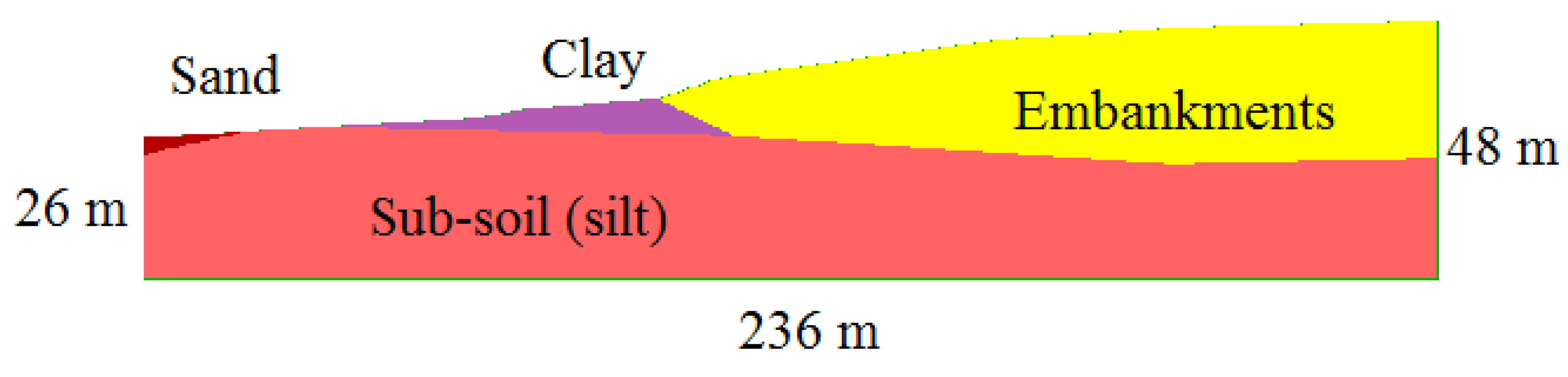
4.2. Model Description

Based on the given geological profile (Figure 2), a model 2D has been constructed in FLAC2D. Figure 6 shows the model 2D dimension and the location of soils that build the mine waste dumps slope. The study site includes a 236 m long (x-axis) and 26 ÷ 48 m high (y-axis) with 4 major built-in soils. All models were conducted, following typical boundary conditions for slope stability analysis: the bottom was fixed, a roller was applied to the sides of the model and the top surface was set free. The model was originally developed as an elastic model to achieve the initial stress state. Then, the displacement and velocity vectors were reset. In the next step, the initial saturation and pore pressure with a constant infiltration rate of intensity (Equations (5) and (6)) were assigned and the model was recalculated.
The rock mass modeled as a Mohr–Coulomb material using a built-in constitutive model available in FLAC2D. A summary of mechanical parameters for numerical modeling are shown in Table 3 and Table 4.

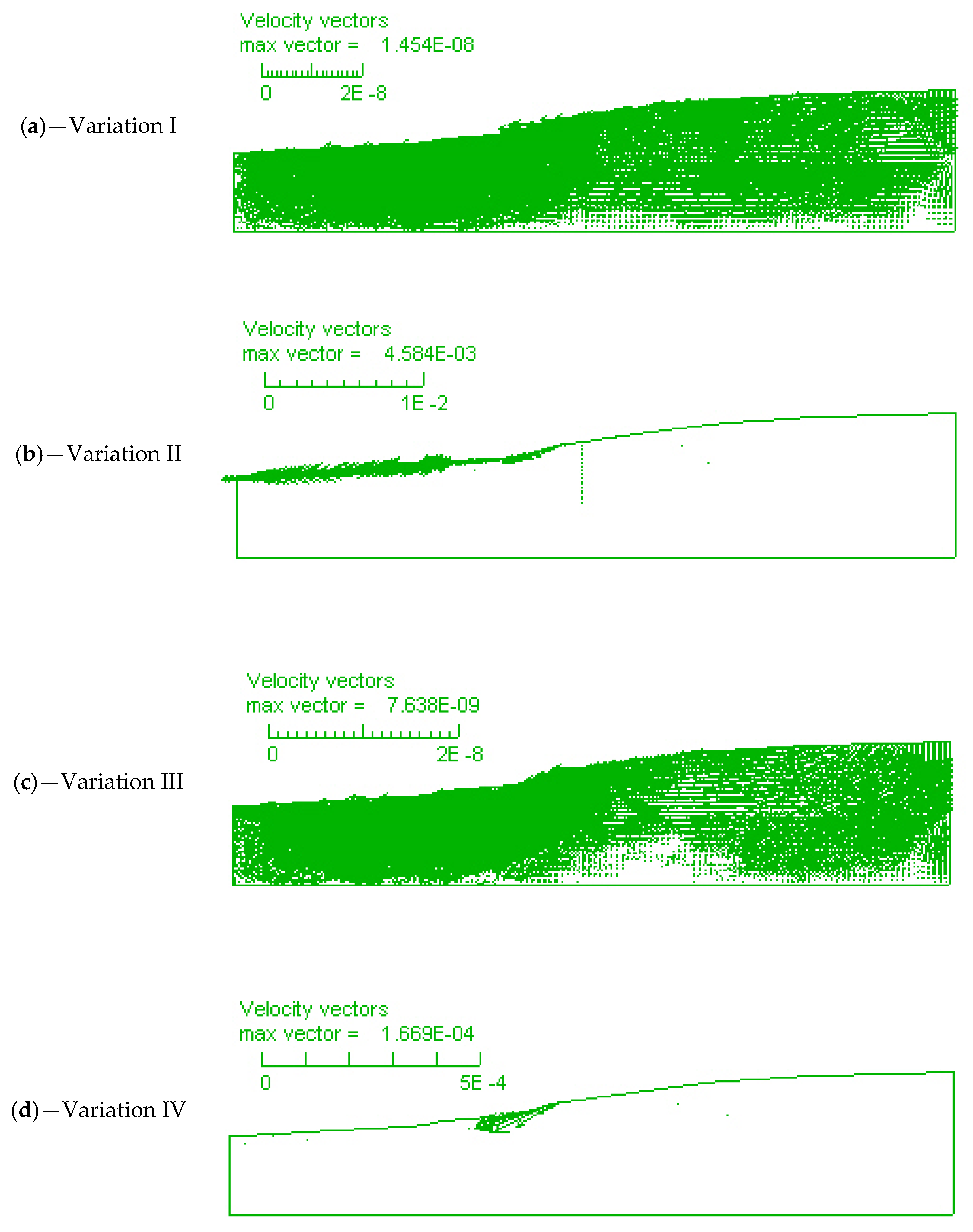
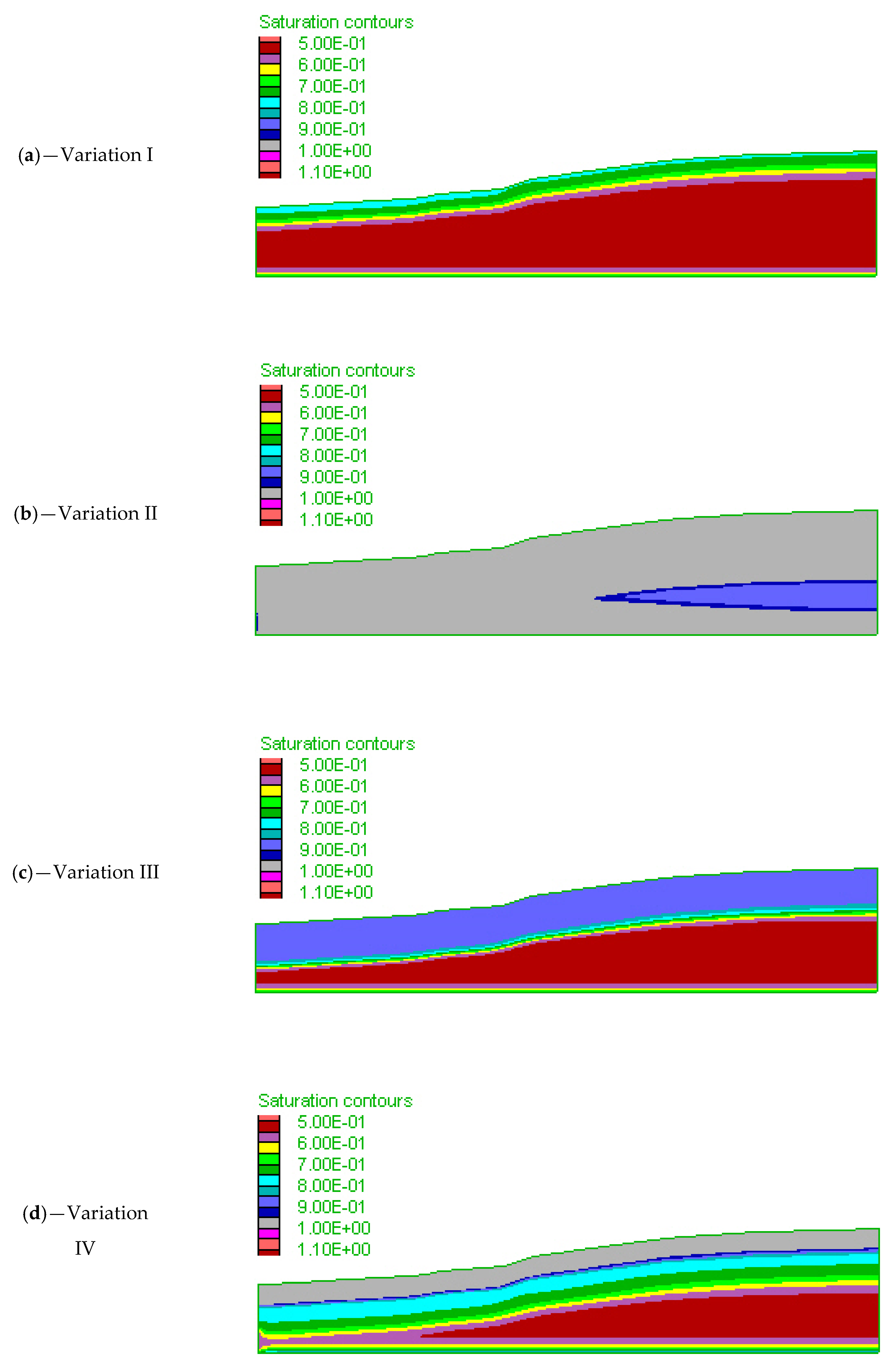
4.3. Calculation Variations

Based on the rainfall data described in Section 3.3, several considerations were purposively taken into account to examine the possible impact of rainfall on the slope stability at the Janina mine waste dump. Calculation considerations are shown in Table 5.
In case of potential landslide, a slope reinforcement for the Janina mine waste dumps against the impact of rainfall will be proposed and recalculated.

4.4. Results Analysis and Discussion

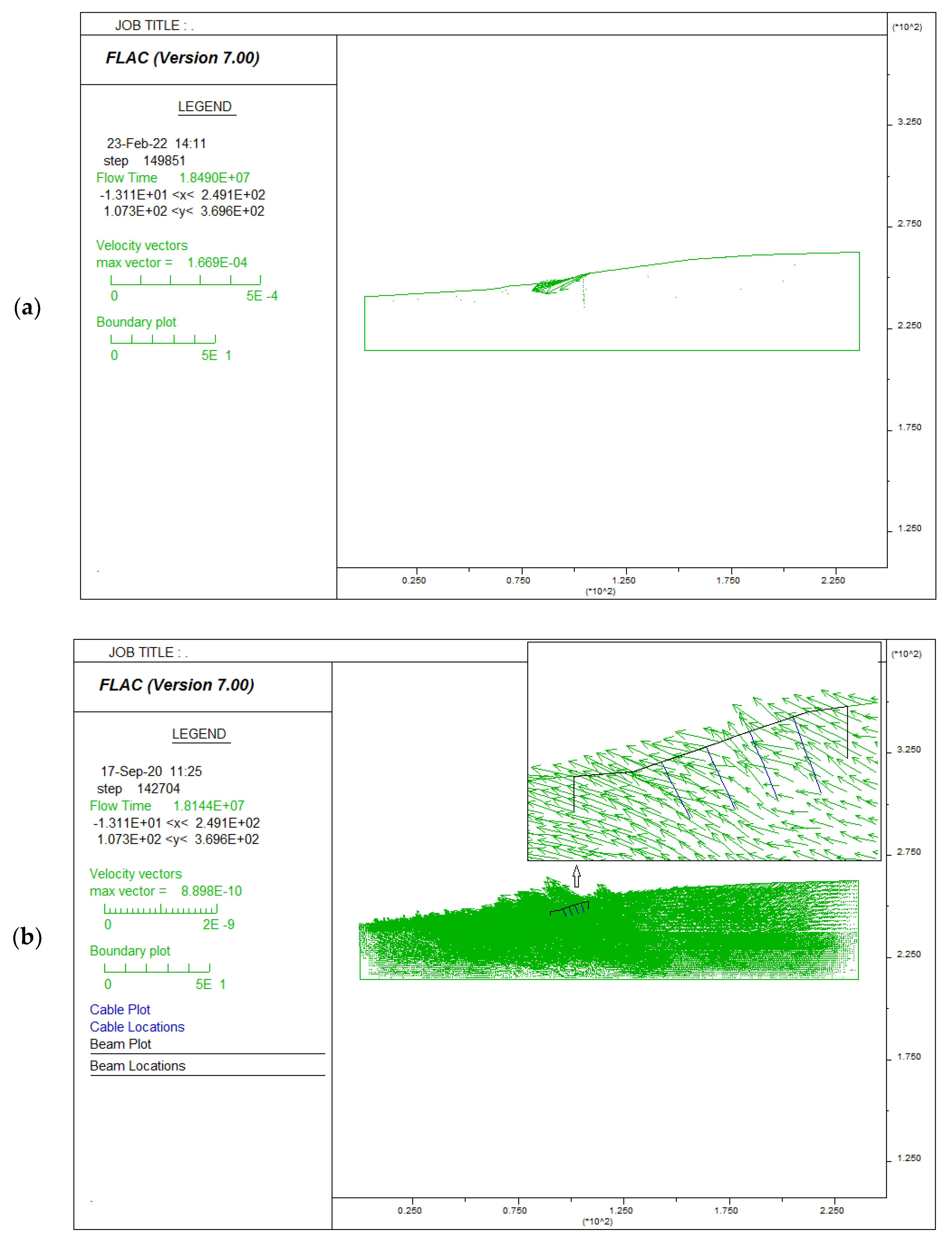
4.4.1. Impact of Rainfall on the Janina Mine Waste Dump Slope

The results of the numerical calculations were presented in the form of maps of velocity vectors and maps of saturation, which enables the assessment of the rainfall impact on slope stability.
Maps of velocity vectors and saturation contours are shown in Figure 7 and Figure 8, respectively.
Values of velocity vectors for Variation I and Variation III are much less than the permissible value (10−5), while values of velocity vectors for Variation II and Variation IV are greater than the permissible value (10−5) (Figure 7). With the initial saturation of 0.84 (Variation IV), the potential landslide is observed on the toe of mine waste layer (Figure 7d), while in variation II, with the initial saturation of 0.89, the potential landslide occurred along the lower part of entire slope (Figure 7b). Maps of velocity vectors indicate that the slope is still stable at the end of the rainfall events in Variation I and Variation III and instable in case of high rainfall intensity, such as variation II and IV. Moreover, higher rainfall intensity can cause a larger landslide.
Maps of saturation indicate that the slope is still stable after the rainfall scenarios in Variation I and Variation III. Value of saturation at the slope surface was less than 0.9 in case of Variation I and Variation III (Figure 8a,c). The slope surface in case of Variation II and Variation III is considered full saturated (close to 1) (Figure 8b,d). The size of saturation inside the slope body was increased with the increase of initial saturation. The increase of saturation is responsible for the subsequent reduction in shear strength (cohesion) of soil and ultimately, failure of slope occurred in case of Variation II and IV.
Numerical modeling results indicate that a rainfall event of low intensity and long duration does not have a significant impact on slope stability. On the other hand, a rainfall event of a high intensity and a short duration was responsible for slope failure. In this case, the behavior was explained by an increase in soil saturation, causing an apparent decrease in soil cohesion.

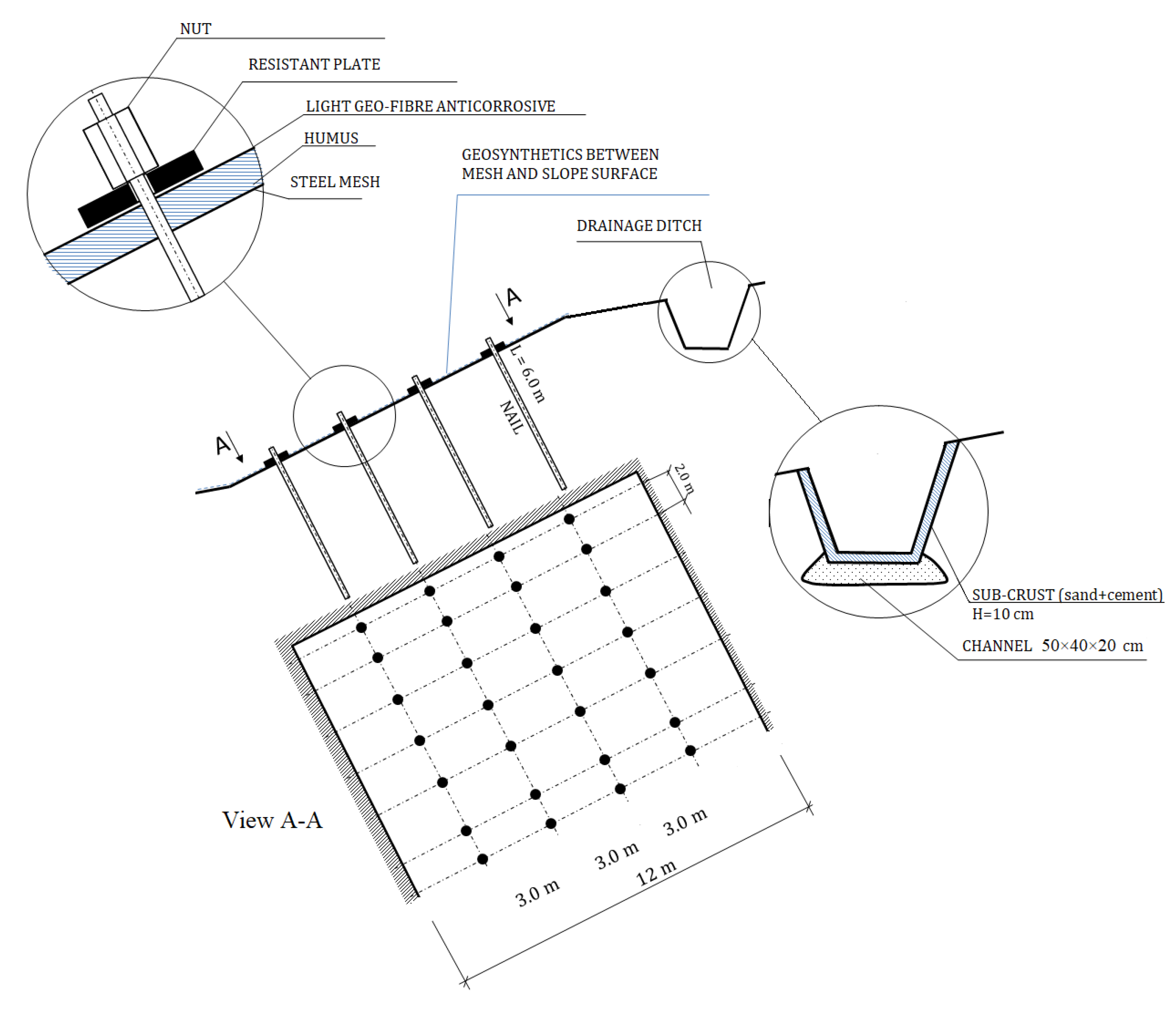
4.4.2. Slope Landslide Prevention under High Rainfall Intensity

The above slope stability analysis has pointed out the potential failure on the slope surface in case of a rainfall event of high intensity and short duration. Therefore, slope reinforcement is required to avoid slope failure in a case of such a rainfall. After determining the location of the potential landslide, slope reinforcement using nailing and steel mesh was proposed for the Janina mine waste dumps against the impact of high rainfall intensity. Once again the same slope stability analysis was conducted with slope reinforcement for an example of Variation IV. Figure 9 presents a scheme of the slope reinforcement, which consists of soil nailing with 6 m long, steel mesh and an anti-erosion geogrid along slope surface with humus soil and grass seeding. Additionally, water drainage will be included in the form of a ditch made of ameliorative concrete channels.
Mechanical parameters of soil nailing and steel mesh for modeling are shown in Table 6.
The numerical modeling results indicate the loss of slope stability under the impact of high rainfall intensity in short duration (Figure 10a)—value of velocity is higher than permissible value (10−5), while slope is considered stable in case of using selected slope reinforcement (Figure 10b)—value of velocity is much lower than the permissible value.
The Janina mine waste dump slope is considered stable at the end of the high intensity of rainfall in short period of time with application of selected slope reinforcement.

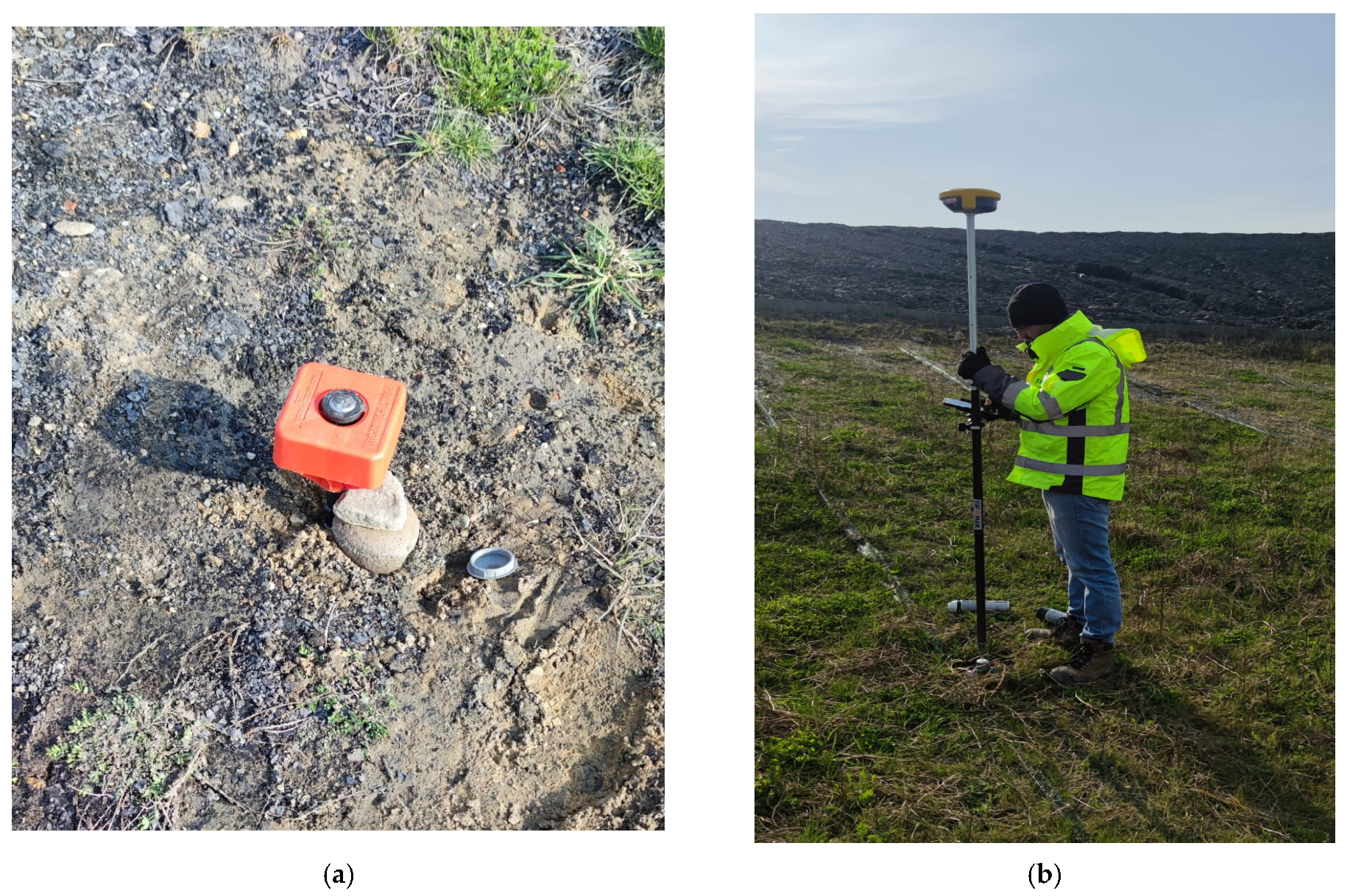
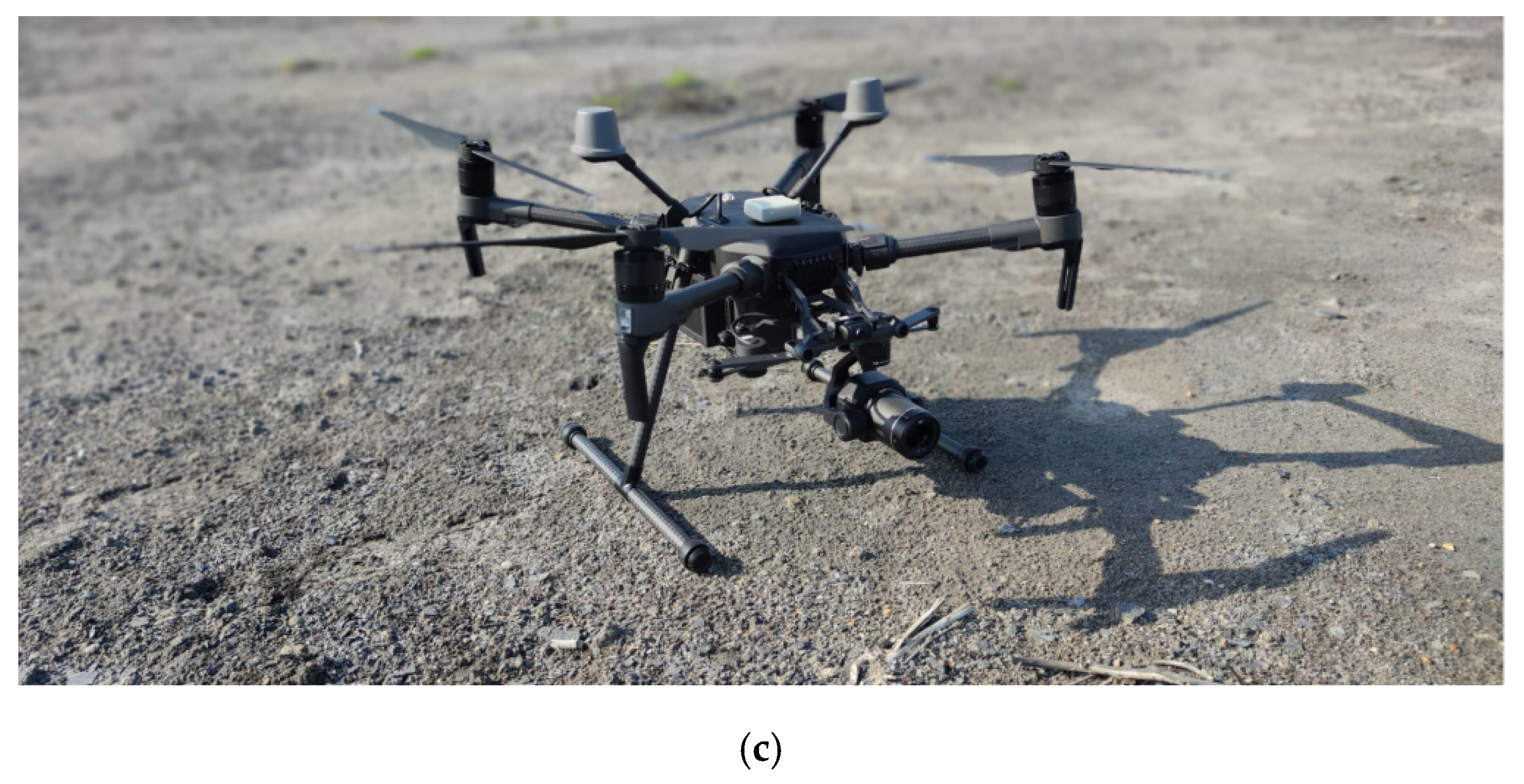
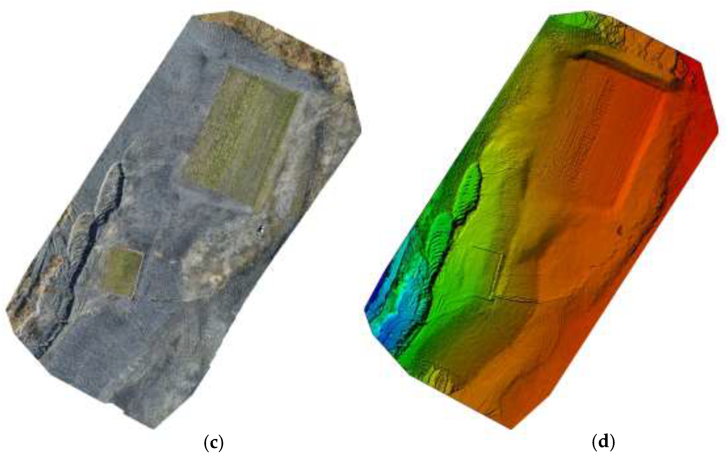
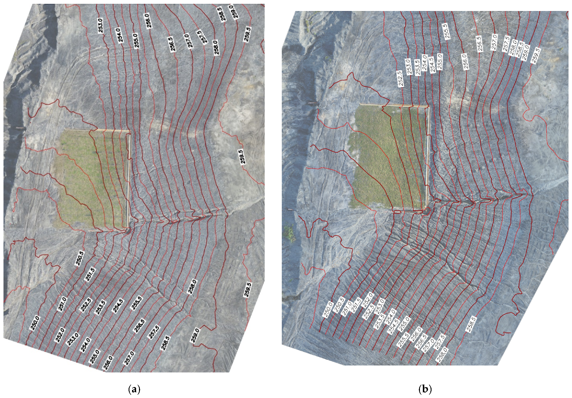
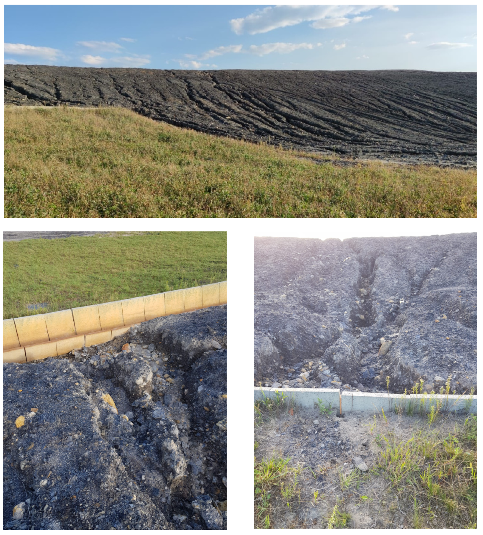
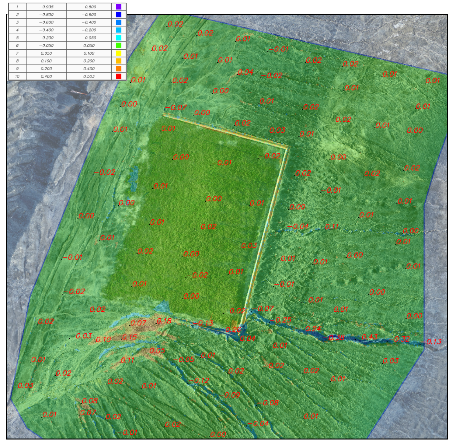
5. Slope Surface Monitoring

In practice, a modern early warning system is commonly recommended to detect the potential landslides and to enable the effective or corrective prevention measures to be taken in a proper moment (period) for slopes. Slope monitoring provides early warning systems against the threat of landslide. Surface monitoring—that is based on a system of geodetic points located on a slope, for which cyclic GPS measurements are made—is one of many slope monitoring methods. Analyzing these measurements allow for the motion of slope and the potential landslide development to be determined [45,46,47,48,49,50,51,52]. Consequently, slope stability can be evaluated and preventative measurements taken if necessary.

5.1. Monitoring System Description for the Janina Mine Waste Dump

Slope monitoring was carried out using the technique of low-altitude aerial photogrammetry with the use of non-metric photos (photogrammetry). This technique is used to measure large (even up to several hundred hectares) and topographically complex surfaces in a very high resolution. The technology involves processing digital photos into a 3D point cloud. This is a spatial, finite representation of the terrain, consisting of X, Y, Z coordinates of points and the color value of each point (pixel). This technique has number of advantages in land surveying with a drone, such as rapid measurement in large areas, precise data, possibility of forming a three-dimensional shape of the complex surfaces, high quality and resolution of images, large amount of data acquired. Photogrammetric air shots are mainly implemented in autonomous mode. The system automatically triggers the camera shutter due to the possibility of setting an appropriate longitudinal and transverse coverage between pictures. Depending on the resolution of the sensor and the set flight altitude, the obtained value of a single field pixel usually results at the level of 1 to 5 cm.
In order to fit the point cloud into the Polish Coordinate System 2000, 11 photo points were established in the studied site (Figure 11a), then measured in 20 epochs with the GEOMAX Zenith 40 receiver (Figure 11b). After the photo points were installed, an autonomous photogrammetric flight with the Phantom 4 RTK Quadrocopter (Figure 11c) was performed from a ceiling of 40 m.

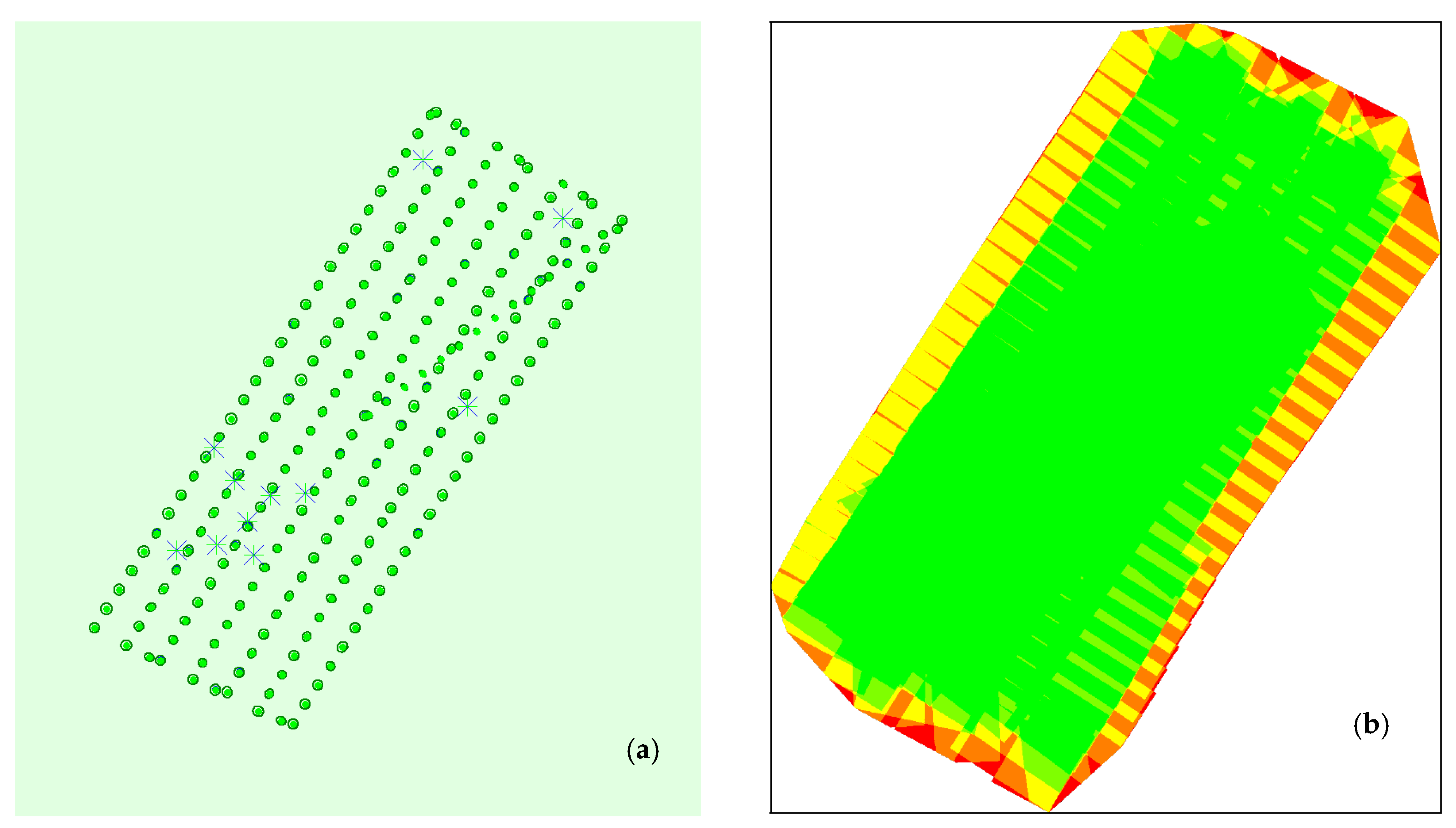
5.2. Monitoring Results Analysis and Discussion

As a result of the photo processing from the photogrammetric flights (19 April–11 August 2022), the following results were obtained: number of photos: 217 ÷ 220, median of the characteristic points found in the photos: 75,115 ÷ 78,484, difference between the initial and calculated camera parameters: 2.85 ÷ 2.89%, median of the common points found per photo: 43,418.9 ÷ 49,612.2, average cloud fit error: 6.8 ÷ 7 mm (Figure 12).
In order to create a contour map, a numerical model was built in the form of a TIN grid (Triangulated Irregular Network) in the AutoCad Civil 3D software (v. 2021) (Figure 13).
In the reinforced part of slope, no soil erosion event was observed, while in the unreinforced part of the slope, strong soil erosion was clearly noticed on the slope surface. It is the presence of raised grasses and water ditch that has stopped the discharged water from the upper part of the slope (Figure 13). The results from slope monitoring indicate that the selected landslide measures, including water drainage and anti-erosion geogrid along slope surface with humus soil and grass seeding, can prevent rainfall-induced soil erosion (Figure 14).
Comparison of size of movements on the mine waste dump slope in the period from 19 April to 11 August 2022 is presented in Figure 15. It can be noted that strong soil erosion was occurred in the unreinforced part of the slope, with the size of decreases up to 0.43 m (upper part)—dark blue. The soil was displaced and accumulated around the channel of water drainage and the lower unreinforced part with the size of increases in a range of 0.2 ÷ 0.4 m (orange and yellow). A slight soil erosion was observed in the reinforced part (studied site) with the size of movements less than 0.03 m. Probably, it is due to the presence of raised grasses. It can be stated that after the rainy season (May, June and July) with an average monthly value of 100 mm rainfall, no significant movement was observed on the slope surface at the studied site, where slope reinforcement has been applied. The monitoring results confirm the numerical modeling results, i.e., slope at the studied site is considered stable after a high rainfall intensity in a short period of time, and the selected slope reinforcement is considered a proper landslide prevention method during high rainfall intensity (rainy season).

6. Conclusions

In the present study, slope stability of the Janina mine waste dump affected by the rainfall was assessed by means of numerical modeling and slope monitoring. The finite difference method FLAC2D was employed to evaluate the slope stability of the Janina mine waste dump with various scenarios of rainfall. Slope monitoring using photogrammetric technique was also applied as an auxiliary element to verify the numerical modeling outcomes and slope reinforcement performance at the studied site. The following conclusions can be drawn:
-
Numerical modelling results highlighted the significant impact of high intensity of rainfall in a short period of time on slope stability of the Janina mine waste dump. In case of high rainfall intensity in a short period of time, the mine waste dump slope tends to lose stability. It is also confirmed by many other researchers in various cases of natural and man-made slopes. Consequently, landslide prevention measures are required for such slopes;
-
Slope monitoring results indicated the significant rainfall-induced soil erosion that was observed on the slope surface of the Janina mine waste dump after the rainy season (3 months). Water drainage and anti-erosion geogrid along slope surface with humus soil and grass seeding are considered useful measures to prevent soil erosion on the slope surface;
-
Based on both modeling and monitoring results, the proposed landslide prevention method with coupling soil nailing and steel mesh is considered a proper method that can improve slope conditions and mitigate instability loss during high rainfall intensity in a short period of time at the Janina mine waste dump. Its application at the Janina mine waste dump can be a reference for other mine waste dumps and is expected to assist mine management to take proper and sufficient slope reinforcement measures to avoid slope instability;
-
As a weather event, rainfall is unpredictable, therefore, landslide prevention measures and a continuous monitoring system (e.g., automated online) are recommended to ensure safety in long-term planning and design of a mine waste dump;
-
This study has pointed out the most important advantages of numerical modeling as a helpful tool for solving complex geotechnical problems, especially when it couples with in situ measurements, such as monitoring data;
-
Future work should focus on the development of landslide risk classification (management) as a result of the precipitation change in the given regions for the mine waste dump slopes and possibility of application of advanced geo-materials (e.g., other mining wastes) for improvement of slope conditions such as the MINRESCUE project.

Author Contributions

Conceptualization, P.M.V.N. and A.W.; methodology, P.M.V.N. and A.W.; software, P.M.V.N.; validation, A.W. and S.R.; formal analysis, P.M.V.N. and A.W.; investigation, P.M.V.N.; resources, R.F.; data curation, P.M.V.N., A.W. and R.F.; writing—original draft preparation, P.M.V.N.; writing—review and editing, P.M.V.N., A.W., S.R. and Z.R.; visualization, A.W. and R.F.; supervision, S.R. and Z.R.; project administration, A.W. and S.R.; funding acquisition, A.W. All authors have read and agreed to the published version of the manuscript.

Funding

This research was performed as a part of the TEXMIN Project (The Impact of EXtreme weather events on MINing operations) and MINRESCUE Project (From Mining Waste to Valuable Resource: New Concepts for a Circular Economy), both funded by the Research Fund for Coal and Steel (RFCS) of the European Union (Grant Agreement No 847250 and 899518, respectively) and by the Polish Ministry of Science and Higher Education (Grant Agreement No 5042/FBWiS/2019/2 and 5167/FBWiS/2021/2, respectively).

Institutional Review Board Statement

Not applicable.

Informed Consent Statement

Not applicable.

Data Availability Statement

Not applicable.

Conflicts of Interest

The authors declare no conflict of interest.

References

  1. CNN. 2022. Available online: https://edition.cnn.com/2022/02/17/americas/brazil-landslides-thursday-intl/index.html (accessed on 30 September 2022).
  2. CNA. 2021. Available online: https://www.channelnewsasia.com/asia/indonesia-landslide-cihanjuang-west-java-dead-injuries-bnpb-398511 (accessed on 30 September 2022).
  3. Kocaman, S.; Tavus, B.; Nefeslioglu, H.A.; Karakas, G.; Gokceoglu, C. Evaluation of Floods and Landslides Triggered by a Meteorological Catastrophe (Ordu, Turkey, August 2018) Using Optical and Radar Data. Geofluids 2020, 8830661. [Google Scholar] [CrossRef]
  4. Collins, B.D.; Corbett, S.C. Terrestrial lidar data of the February 14, 2019, Sausalito Boulevard landslide, Sausalito, California. U.S. Geol. Surv. Data Ser. 2019, 1112, 12. [Google Scholar] [CrossRef]
  5. Lazzari, M.; Piccarreta, M. Landslide Disasters Triggered by Extreme Rainfall Events: The Case of Montescaglioso (Basilicata, Southern Italy). Geosciences 2018, 8, 377. [Google Scholar] [CrossRef] [Green Version]
  6. Mori, A.; Subramanian, S.S.; Ishikawa, T.; Komatsu, M. A Case Study of a Cut Slope Failure Influenced by Snowmelt and Rainfall. Procedia Eng. 2017, 189, 533–538. [Google Scholar] [CrossRef]
  7. Remaitre, A.; Malet, J.P.; Cepeda, J.M. Landslides and debris flows triggered by rainfall: The Barcelonnette basin case study, south French Alps. Mt. Risks Bringing Sci. Soc. 2018, 141–145. Available online: https://www.researchgate.net/publication/288007519_Landslides_and_debris_flows_triggered_by_rainfall_the_Barcelonnette_basin_case_study_south_French_Alps (accessed on 30 September 2022).
  8. Devoli, G.; Cepeda, J.; Kerle, N. The 1998 Casita volcano flank failure revisited—New insights into geological setting and failure mechanisms. Eng. Geol. 2009, 105, 65–83. [Google Scholar] [CrossRef]
  9. Gupta, G.; Sharma, S.K.; Singh, G.S.P.; Kishore, N. Numerical Modelling-Based Stability Analysis of Waste Dump Slope Structures in Open-Pit Mines—A Review. J. Inst. Eng. India Ser. D 2021, 102, 589–601. [Google Scholar] [CrossRef]
  10. Gao, Y.; Yin, Y.; Li, B.; Wang, W.P.; Zhang, N.; Yang, C.; Zuo, X. Investigation and dynamic analysis of the long runout catastrophic landslide at the Shenzhen landfill on December 20, 2015, in Guangdong, China. Environ. Earth Sci. 2017, 76, 13. [Google Scholar] [CrossRef]
  11. Adibee, N.; Osanloo, M.; Rahmanpour, M. Adverse effects ofcoal mine waste dumps on the environment and their management. Environ. Earth Sci. 2013, 70, 1581–1592. [Google Scholar] [CrossRef]
  12. Steiakakis, E.; Kavouridis, K.; Monopolis, D. Large scale failure of the external waste dump at the “south field” lignite mine, northern Greece. Eng. Geol. 2009, 104, 269–279. [Google Scholar] [CrossRef]
  13. Blight, G.E.; Fourie, A. Catastrophe revisited—Disastrous flow failures of mine and municipal solid waste. Geotech. Geol. Eng. 2005, 23, 219–248. [Google Scholar] [CrossRef]
  14. Dawson, R.F.; Morgenstern, N.R.; Stokes, A.W. Liquefaction flow slides in Rocky Mountains coal mine waste dumps. Can. Geotech J. 1998, 35, 328–343. [Google Scholar] [CrossRef]
  15. Ulusay, R.; Arikan, F.; Yoleri, M.F.; Caglan, D. Engineering geological characterization of coal mine waste material and an evaluation in the context of back-analysis of spoil pile instabilities in a strip mine, SW Turkey. Eng. Geol. 1995, 40, 77–101. [Google Scholar] [CrossRef]
  16. Siddle, H.J.; Wright, M.D.; Hutchinson, J.N. Rapid failures of colliery spoil heaps in the South Whales coalfield. Q. J. Eng.Geol. 1996, 29, 103–132. [Google Scholar] [CrossRef]
  17. Shakesby, R.A.; Whitlow, J.R. Failure of a mine waste dump in Zimbabwe: Causes and consequences. Environ. Geol. Water Sci. 1991, 18, 143–153. [Google Scholar] [CrossRef]
  18. Gariano, S.L.; Guzzetti, F. Landslides in a changing climate. Earth-Sci. Rev. 2016, 162, 227–252. [Google Scholar] [CrossRef] [Green Version]
  19. Kovrov, O.; Kolesnyk, V.; Buchavyi, Y. Development of the landslide risk classification for natural and man-made slopes based on soil watering and deformation extent. Min. Miner. Depos. 2020, 14, 105–112. [Google Scholar] [CrossRef]
  20. Skrobala, V.; Popovych, V.; Pinder, V. Ecological patterns for vegetation cover formation in the mining waste dumps of the Lviv-Volyn coal basin. Min. Miner. Depos. 2020, 14, 119–127. [Google Scholar] [CrossRef]
  21. Petley, D. Global patterns of loss of life from land-slides. Geology 2012, 40, 927–930. [Google Scholar] [CrossRef]
  22. Crozier, M.J. Deciphering the effect of climate change on landslide activity: A review. Geomorphology 2010, 124, 260–267. [Google Scholar] [CrossRef]
  23. Kovrov, O.S.; Kolesnik, V.Y.; Buchavyi, Y.V. Evaluationof the influence of climatic and geomorphological factors on landslides development. Environ. Saf. Nat. Resour. 2018, 25, 121–132. [Google Scholar] [CrossRef]
  24. Smoliński, A.; Dombek, V.; Pertile, E.; Drobek, L.; Gogola, K.; Żechowska, S.W.; Magdziarczyk, M. An analysis of self-ignition of mine waste dumps in terms of environmental protection in industrial areas in Poland. Sci. Rep. 2021, 11, 8851. [Google Scholar] [CrossRef] [PubMed]
  25. Stracher, G.B.; Prakash, A.; Sokol, E.V. Chapter 16—Coal Mining and Combustion in the Coal Waste Dumps of Poland. In Coal and Peat Fires: A Global Perspective; Elsevier: Amsterdam, The Netherlands, 2015; pp. 463–473. [Google Scholar] [CrossRef]
  26. Szczepanska, J.; Twardowska, I. Distribution and environmental impact of coal-mining wastes in Upper Silesia, Poland. Environ. Geol. 1999, 38, 249–258. [Google Scholar] [CrossRef]
  27. Itasca Consulting Group Inc. FLAC (2D) Version 6.0, User’s Guide; Itasca Consulting Group Inc.: Minneapolis, MN, USA, 2008. [Google Scholar]
  28. Schmertmann, J.H. Estimating slope stability reduction due to rain infiltration mounding. J. Geotech. Geoenviron. Eng. 2006, 132, 1219–1228. [Google Scholar] [CrossRef]
  29. Yellishetty, M.; Darlington, W.J. Effects of monsoonal rainfall on waste dump stability and respective geo-environmental issues: A case study. Environ. Earth Sci. 2011, 63, 1169–1177. [Google Scholar] [CrossRef]
  30. Zhao, X.; Gao, X.; Li, D. The stability analysis of Nantong coal mine waste dump, Chongqing and prevention measures. Appl. Mech. Mater. 2012, 204–208, 3526–3531. [Google Scholar] [CrossRef]
  31. Song, Y. Numerical analysis of the seepage from and stability of a mine waste-dump slope during rainfall. J. Eng. Geol. 2015, 25, 57–66. [Google Scholar] [CrossRef] [Green Version]
  32. Koner, R.; Chakravarty, D. Numerical analysis of rainfall effects in external overburden dump. Int. J. Min. Sci. Technol. 2016, 26, 825–831. [Google Scholar] [CrossRef]
  33. Wei, L.; Zhang, Y.; Zhao, Z.; Zhong, X.; Liu, S.; Mao, Y.; Li, J. Analysis of Mining Waste Dump Site Stability Based on Multiple Remote Sensing Technologies. Remote Sens. 2018, 10, 2025. [Google Scholar] [CrossRef] [Green Version]
  34. Zhu, J.F.; Chen, C.F.; Zhao, H.Y. An Approach to Assess the Stability of Unsaturated Multi-layered Coastal Embankment Slope during Rainfall Infiltration. J. Mar. Sci. Eng. 2019, 7, 165. [Google Scholar] [CrossRef]
  35. Masoudian, M.S.; Hashemi, M.A.; Tasalloti, A.; Marshall, A.M. A general framework for coupled hydro-mechanical modelling of rainfall- induced instability in unsaturated slopes with multi-variate random fields. Comput. Geotech. 2019, 115, 103162. [Google Scholar] [CrossRef]
  36. Igwe, O.; Chukwu, C. Slope stability analysis of mine waste dumps at a mine site in Southeastern Nigeria. Bull. Eng. Geol. Environ. 2019, 78, 2503–2517. [Google Scholar] [CrossRef]
  37. Różański, Z.; Wrona, P.; Pach, G.; Niewiadomski, A.P.; Markowska, M.; Wrana, A.; Frączek, R.; Balcarczyk, L.; Vaquero Quintana, G.; de Paz Ruiz, D. Influence of water erosion on fire hazards in a coal waste dump—A case study. Sci. Total Environ. 2022, 834, 155350. [Google Scholar] [CrossRef] [PubMed]
  38. Chudek, M.; Kleta, H.; Chudek, M.D.; Lamparski, H. Analiza Przemieszczeń Gruntu w Otoczeniu Budowy Obiektu Użyteczności Publicznej pn. Trzy Wzgórza z Wykorzystaniem Inklinometrów dla Opracowania Koncepcji i Sposobu Stabilizacji Zjawiska w Aspekcie Ochrony Obiektów Powierzchniowych przy ul. Dąbrowskiego w Libiążu dla Tauron Wydobycie S.A. Przedsiębiorstwo Produkcyjno-wdrpżeniowe ‘MIDACH’ Sp. z o. o.; Centrum Badawczo-Rozwojowe: Katowice, Poland, 2017; (Unpublished). (In Polish)
  39. IMGW-PIB. IMGW-PIB Report: Polish Climate 2021. Institute of Meteorology and Water Management. 2022. Available online: https://www.imgw.pl/sites/default/files/2022-04/imgw-pib_raport-klimat-polski_2021_0.pdf (accessed on 30 September 2022). (In Polish).
  40. IOŚ-PIB. The Knowledge Base on Climate Change and Adapting to Climate Change Impacts, Together with Knowledge Dissemination Channels, to Strengthen Economic, Environmental and Societal Resilience as well as to Support Management of Extraordinary Risks Associated with Climate Change. Institute of Environmental Protection—National Research Institute. 2021. Available online: https://klimada2.ios.gov.pl/klimat-scenariusze-portal/ (accessed on 30 September 2022). (In Polish)
  41. Van Genuchten, M.T. A Closed Form Equation for Predicting the Hydraulic Conductivity of Unsaturated Soils. Soil Sc. Soc. Am. J. 1980, 44, 892–898. [Google Scholar] [CrossRef] [Green Version]
  42. Bear, J. Hydraulics of Groundwater; McGraw-Hill: New York, NY, USA, 1979. [Google Scholar]
  43. Dangla, P. Approches Energetique et Numerique des Milieux Poreux Non Satures. Memoire D’habilitation a Diriger des Recherches; Ecole Nationale des Ponts et Chaussees: Marne-la-Vallée, France; Ecole Normale Superieure de Cachan: Gif-sur-Yvette, France; Universite de Marne-la-Valee: Paris, France, 1999. [Google Scholar]
  44. Hutter, K.; Laloui, L.; Vulliet, L. Thermodynamically Based Mixture Models of Saturated and Unsaturated Soils. In Mechanics of Cohesive-Frictional Materials; Darve, F., de Borst, R., Eds.; Wiley: Hoboken, NJ, USA, 1999; Volume 4, pp. 295–338. [Google Scholar]
  45. Bazaluk, O.; Rysbekov, K.; Nurpeisova, M.; Lozynskyi, V.; Kyrgizbayeva, G.; Turumbetov, T. Integrated monitoring for the rock mass state during large-scale subsoil development. Front. Environ. Sci. 2022, 10, 852591. [Google Scholar] [CrossRef]
  46. Dong, K.; Yang, D.; Chen, J.; Zhou, J.; Li, J.; Lu, X.; Kou, Q. Monitoring-data mechanism-driven dynamic evaluation method for slope safety. Comput. Geotech. 2022, 148, 104850. [Google Scholar] [CrossRef]
  47. Kim, D.; Langley, R.B.; Bond, J.; Chrzanowski, A. Local Deformation Monitoring Using GPS in an Open Pit Mine: Initial Study. GPS Solut. 2003, 7, 176–185. [Google Scholar] [CrossRef]
  48. Nurpeissova, M.; Bekbassarov, S.; Bek, A.; Kyrgizbaeva, G.; Turisbekov, S.; Ormanbekova, A. The Geodetic Monitoring of the Engineering Structures Stability Conditions. J. Eng. Appl. Sci. 2020, 12, 9151–9163. [Google Scholar] [CrossRef]
  49. Di Maio, C.; Fornaro, G.; Gioia, D.; Reale, D.; Schiattarella, M.; Vassallo, R. In situ and satellite long-term monitoring of the Latronico landslide, Italy: Displacement evolution, damage to buildings, and effectiveness of remedial works. Eng. Geol. 2018, 245, 218–235. [Google Scholar] [CrossRef]
  50. Peng, M.; Li, X.Y.; Li, D.Q.; Jiang, S.H.; Zhang, L.M. Slope safety evaluation by integrating multi-source monitoring information. Struct. Saf. 2014, 49, 65–74. [Google Scholar] [CrossRef]
  51. Kumar, A.; Rathee, R. Monitoring and evaluating of slope stability for setting out of critical limit at slope stability radar. Geo-Engineering 2017, 8, 18. [Google Scholar] [CrossRef]
  52. Yang, P.P.; Wang, N.Q.; Jiang, Z.Y.; Yang, Y.; Yan, H.P. Overview of slope monitoring technology. IOP Conf. Mater. Sci. Eng. 2019, 472, 012009. [Google Scholar] [CrossRef]
Figure 1. Location of ditch failure with a section of 300 m long, marked in pink.
Energies 15 08311 g001
Figure 2. The failure observed on the surface of the Janina mine waste dump (10 February 2017).
Energies 15 08311 g002
Figure 3. Location of the Janina mine waste dump.
Energies 15 08311 g003
Figure 4. Overburden profile of the studied site at the Janina mine waste dump [38].
Energies 15 08311 g004
Figure 5. Average monthly amount of precipitation by decade in the Janina mine waste dump region (Chrzanowski county, Poland).
Energies 15 08311 g005
Figure 6. Model 2D and location of soil layers in slope.
Energies 15 08311 g006
Figure 7. Maps of velocity vectors.
Energies 15 08311 g007
Figure 8. Model 2D and location of soil layers in slope.
Energies 15 08311 g008
Figure 9. Scheme of slope reinforcement for the Janina mine waste dumps against the impact of high rainfall intensity.
Energies 15 08311 g009
Figure 10. Maps of velocity vectors in Variation IV as an example: (a) without any slope protection, (b) with slope reinforcement using nailing and steel mesh.
Energies 15 08311 g010
Figure 11. Slope monitoring devices: (a) Photo point, (b) GEOMAX Zenith 40 receiver, (c) Phantom 4 RTK Quadrocopter.
Energies 15 08311 g011aEnergies 15 08311 g011b
Figure 12. An example of photo processing: (a) Initial Image Positions, (b) Overlap between images (c) Orthophoto map, (d) Numerical model of studied area coverage (19 April 2022).
Energies 15 08311 g012aEnergies 15 08311 g012b
Figure 13. Orthophoto maps with contour lines of the studied site: (a) 19 April 2022; (b) 11 August 2022.
Energies 15 08311 g013
Figure 14. The applied reinforcement has prevented rainfall-induced soil erosion.
Energies 15 08311 g014
Figure 15. Map of size of increases (+) and decreases (−) on the mine waste dump slope (m).
Energies 15 08311 g015
Table 1. Case studies on the impact of rainfall on the mine waste dump slope.
Author(s), YearApplied MethodLandslide MeasuresMajor Findings
Schmertmann, 2006 [28]Numerical methodNoThe following variables that will impact stability of the manmade slope: rainfall intensity and duration, soils permeability, slope angle, impermeable/permeable underlayer
Yellishetty and Darlington, 2011 [29]Numerical method (SLOPE/W)No Impact of monsoon rainfalls on the slope factor of safety is very dramatic
Zhao et al., 2012 [30]Limiting Equilibrium method and numerical simulation method (FLAC2D)Seven landslide prevention measuresSlope landslide will occur easily in case of long heavy rainfall
Song, 2015 [31]Numerical method (SEEP/W, SLOPE/W)No Safety factor of the slope decreased as the wetting front moved down due to rainfall infiltration
Koner and Chakravarty, 2016 [32]Finite Difference Method with Shear Strength Reduction technique (FLAC2D)NoGeo-material properties, slope geometry and intensity of rainfall had a significant effect on the stability of a dump slope structure at the Wardha Valley Coalfields
Wei et al., 2018 [33]Multiple remote sensing technologies (SBAS, IRT) and numerical simulation based on the Limiting Equilibrium methodNo Water-bearing aquifer layers are probably weak layers after intense rainfall and they are considered a dangerous area in terms of landslides
Zhu et al., 2019 [34]Modified Morgenstern–Price (M–P) method coupled with Random Search
Algorithm (RSA)
NoThe stability of the unsaturated multi-layered embankment slope was gradually reduced with the increase of rainfall infiltration
Masoudian et al., 2019 [35]Monte-Carlo simulation and Finite Element Method (Abaqus)No As a result, the probability of failure increased from nearly zero to almost 100% during 10 days of rainfall, which indicates the significant impact of rainfall infiltration on stability of unsaturated slopes.
Igwe and Chukwu, 2019 [36]Numerical method (GeoStudio® 2012)No Steep slopes, slope curvature, high clay contents, high water content, rainfall and poor shear strength have been pointed out as the main factors that would negate the slope stability
Table 2. Geotechnical characteristics of soils at the studied site (the Janina mine waste dump) [38].
SeriesSoil LayerMaterialPlastic LimitGeotechnical Parameters
I—EmbankmentsI-1Sandy formations with an admixture of clay, humus and gravels--
I-2Mine waste materials of claystone, mudstone, shale, sandstone and coal--
II—Quaternary sedimentsII-1Fine-grained sand0.4Young’s modulus (E): 38 MPa
Friction angle (φ): 29.9 deg.
II-2Medium-grained sand0.4Young’s modulus (E): 67 MPa
Friction angle (φ): 32.3 deg.
II-3Silty loam0.35Young’s modulus (E): 15 MPa
Friction angle (φ): 12.4 deg.
Cohesion (c): 11.9 kPa
II-4Silty loam0.15Young’s modulus (E): 23 MPa
Friction angle (φ): 15.6 deg.
Cohesion (c): 19.2 kPa
III—NeogeneIII-1Silty clay with admixture of fine-grained0.33Young’s modulus (E): 10 MPa
Friction angle (φ): 8.6 deg.
Cohesion (c): 42.7 kPa
III-2Silty clay with admixture of fine-grained0.26Young’s modulus (E): 11.8 MPa
Friction angle (φ): 9.5 deg.
Cohesion (c): 46.1 kPa
III-3Silty clay with admixture of fine-grained0.24Young’s modulus (E): 12.5 MPa
Friction angle (φ): 9.8 deg.
Cohesion (c): 47.1 kPa
III-4Silty clay with admixture of fine-grained0.15Young’s modulus (E): 15.3 MPa
Friction angle (φ): 11 deg.
Cohesion (c): 51.6 kPa
III-5Silty clay0.07Young’s modulus (E): 18.6 MPa
Friction angle (φ): 12.1 deg.
Cohesion (c): 55.9 kPa
III-6Silty clay0.03Young’s modulus (E): 20.5 MPa
Friction angle (φ): 12.6 deg.
Cohesion (c): 58.2 kPa
Table 3. Mechanical parameters of soils adopted for modeling.
Rock TypeYoung’s Modulus E, MPaPoisson’s Ratio υ Tensile Strength   σ t ,   MPa Cohesion
c, kPa
Angle of Internal Friction
θ, °
Density ρ [kg/m3]
Silt200.3070112000
Embankment400.400302200
Sand 600.300301970
Clay200.3040151950
Table 4. Fluid (water) properties for modeling.
Fluid ParametersValue
Wetting fluid density 1000 kg/m3
Non-wetting fluid density0.0 kg/m3
van Genuchten parameter a0.336
van Genuchten parameter b0.0
van Genuchten parameter P00.015
Wetting fluid modulus1.0 MPa
Non-wetting fluid modulus1.0 Pa
Residual saturation0.0
Table 5. Calculation variations.
Acc. IMGW-PIB Report [39,40]Worst-Case Scenarios
I (Regular)II (Critical)IIIIV
Rainfall100 mm90 mmYearly rainfall
(900 mm)
Quarterly rainfall
(250 mm)
Period of time1 month1 day3 months (V, VI, VII)—rainy season4 days
Calculated initial saturation (Equation (5))0.560.890.660.84
Calculated initial pore pressure (Equation (6)), kPa41.4 8.427.211.6
Table 6. Mechanical parameters of soil nailing and steel mesh.
ParametersValue
Soil nailingRadius0.015 m
Young’s modulus200 GPa
Yielding moment487 Nm
Load bearing capacity125 kN
Max. strain0.01 m
Steel meshArea1.7 × 10−4 m2
Inertia moment10−10 m4
Young’s modulus16 GPa
Tensile strength1000 MPa
Yielding moment0.1 Nm
Publisher’s Note: MDPI stays neutral with regard to jurisdictional claims in published maps and institutional affiliations.

