Review

A Review of Molten Salt Reactor Multi-Physics Coupling Models and Development Prospects

1
Shanghai Institute of Applied Physics, Chinese Academy of Sciences, Shanghai 201800, China
2
CAS Innovative Academy in TMSR Energy System, Chinese Academy of Sciences, Shanghai 201800, China
3
University of Chinese Academy of Sciences, Beijing 100049, China
*
Author to whom correspondence should be addressed.
Energies 2022, 15(21), 8296; https://doi.org/10.3390/en15218296
Submission received: 11 September 2022 / Revised: 18 October 2022 / Accepted: 2 November 2022 / Published: 6 November 2022

Abstract

:
Molten salt reactors (MSRs) are one type of GEN-IV advanced reactors that adopt melt mixtures of heavy metal elements and molten salt as both fuel and coolant. The liquid fuel allows MSRs to perform online refueling, reprocessing, and helium bubbling. The fuel utilization, safety, and economics can be enhanced, while some new physical mechanisms and phenomena emerge simultaneously, which would significantly complicate the numerical simulation of MSRs. The dual roles of molten fuel salt in the core lead to a tighter coupling of physical mechanisms since the released fission energy will be absorbed immediately by the molten salt itself and then transferred to the primary heat exchanger. The modeling of multi-physics coupling is regarded as one important aspect of MSR study, attracting growing attention worldwide. Up to now, great efforts have been made in the development of MSR multi-physics coupling models over the past 60 years, especially after 2000, when MSR was selected for one of the GEN-IV advanced reactors. In this paper, the development status of the MSR multi-physics coupling model is extensively reviewed in the light of coupling models of N-TH (neutronics and thermal hydraulics), N-TH-BN (neutronics, thermal hydraulics, and burnup) and N-TH-BN-G (neutronics, thermal hydraulics, burnup, and graphite deformation). The problems, challenges, and development trends are outlined to provide a basis for the future development of MSR multi-physics coupling models.

1. Introduction

Molten salt reactors (MSRs) are liquid-fueled reactors characterized by their capabilities of online refueling, reprocessing, and helium bubbling to remove sparingly soluble fission products. The high utilization of thorium can be achieved in MSRs since 233Pa, which is an intermediate nuclide in the evolution chain of 232Th to 233U and has a half-life of 27 days, can be extracted from the core in a timely manner to reduce its neutron absorption [1]. Liquid-fueled MSRs are, hence, often associated with the 232Th-233U fuel cycle. Th-based fuel cycles are well known to have lower equilibrium radiotoxicity than U-based fuel cycles due to the much lower transuranic production from 232Th than from 238U. Therefore, MSRs also have the potential to greatly reduce the inventory of long-lived high-level radioactive wastes [2]. Other merits derived from the liquid fuel, including low excess reactivity over the core operation cycle and exemption from fuel cell manufacture, can also be provided by MSRs. Because of these unique features, MSRs have attracted growing attention worldwide, especially after they were selected as one of the GEN-IV reactor concepts in 2002 [3]. A series of MSR concepts, sorted by the neutron spectrum (thermal/epithermal/fast), molten salt (fluoride/chlorine), moderator (graphite/heavy water/ZrH), and power scale (micro/small-modular/large), have been proposed since the molten salt reactor experiment (MSRE), with a thermal power of 8 MW, was built and operated successfully in the 1960s by the Oak Ridge National Laboratory (ORNL) [4,5,6,7,8,9,10,11,12].
As in solid-fueled reactors, MSR engineering is a complex intersection of multiple physics, encompassing neutronics, thermal hydraulics, chemistry, and materials science. Besides this, it possesses other unique physical mechanisms, including fuel flow and continuous fission-product removal using physical (helium sparging) and pyrochemical processes, etc. [13,14,15,16]. A closer mutual interaction among the multiple physical mechanisms compared with solid-fueled reactors can also be observed in MSRs since fuel salt acts as both fuel and coolant [5]. A multi-physics coupling simulation is, hence, of great importance in MSR numerical calculation, directly influencing the core design and safety analysis. Since the 1960s, great efforts have been made regarding the development of an MSR multi-physics coupling model, especially in the aspects of neutronics and thermal hydraulics (N-TH) coupling. The point neutronic kinetics coupling with lumped parameter thermal hydraulics was the first N-TH coupling model developed by ORNL in the 1960s [17]. The delayed neutron precursor flowing out from the core was analytically modeled, based on the core residence time and external loop transit time. Afterward, the spatial effects of the MSR parameters were gradually taken into account, along with the approach employed in the neutronics and thermal hydraulics of nuclear reactors [18,19,20]. Furthermore, since 2002, various coupling solution strategies, methods, and solution methods were introduced to the MSR N-TH coupling model, causing the N-TH analysis model to approach a real MSR core operational condition with little approximation necessary [21,22,23,24,25]. Meanwhile, coupling other physical mechanisms, such as online refueling and reprocessing, helium bubbling, and dimensional changes of graphite, to the N-TH model is also currently being explored, thanks to a great improvement in computing technologies [26,27,28,29]. Nevertheless, the existing multi-physics coupling models of MSR should be further improved in the aspects of completeness and calculation cost.
In this paper, research activities regarding the development of an MSR multi-physics coupling model are extensively reviewed, aiming to identify the research trends and challenges. The paper is expected to provide a foundation/reference for those scholars who are interested in an MSR multi-physics coupling study. A comprehensive view of MSR research and development (R&D) worldwide and the main multi-physics mechanisms of MSR are provided in Section 2. The MSR multi-physics coupling models are then reviewed in Section 3. Section 4 gives the prospects for the development of an MSR multi-physics coupling model. Finally, our conclusions are drawn in Section 5.

2. R&D and Main Features of MSR

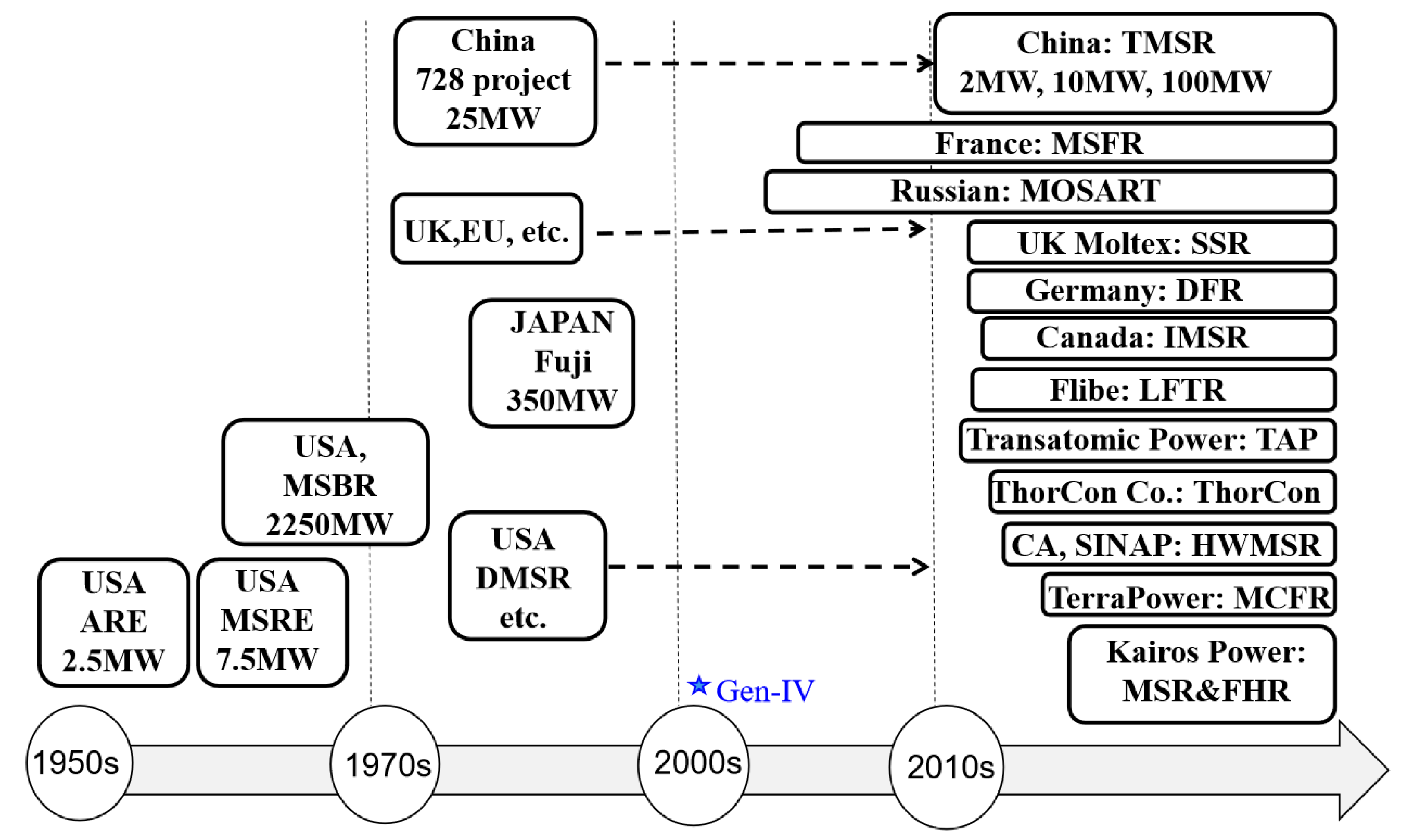
2.1. MSR R&D Worldwide

MSR is an old concept; its R&D activities have continued for around 70 years and have undergone ups and downs but have gained a great deal of attention worldwide since the beginning of the year 2000. An overview of the historical and current status of MSR R&D activities worldwide is shown in Figure 1. In the 1950s, ORNL built its first MSR, known as the aircraft reactor experiment (ARE), under the support of the US Aircraft Nuclear Propulsion program. This MSR adopted molten fluoride salt, NaF-ZrF4-UF4 (53-41-6 mol%), as the fuel, with beryllium oxide (BeO) as the moderator. It achieved criticality in 1954 and operated successfully for 100 h at a steady state [30]. Researchers then turned to MSR civilian applications for electricity production in the 1960s. A molten salt reactor experiment (MSRE) with a thermal power of 7.3 MW was built by ORNL in 1965 and was successfully operated for over 4.5 years by sequentially using 235U, 239Pu, and 233U fuels [6,31]. In parallel with the R&D of MSRE, the design activities of breeder MSRs were carried out by ORNL with the aim of breeding 233U from 232Th. From 1960 to 1968, a series of molten salt-breeder reactor (MSBR) concepts were proposed. A two-region two-fluid graphite-moderated and reflected thermal reactor concept with an electrical power of 1000 MW was the first proposed design of MSBR. In this design, two FLiBe salt fluids, dissolved with 233U and 232Th, respectively, were separated by the graphite structure, forming an inner core driver zone and an outer core blanket zone [32]. For both fluids, continuous fuel reprocessing and off-gas systems were planned. The Th-U breeding ratio (BR) could achieve around 1.06. Thereafter, several MSBR designs, including a modular MSBR (MMSBR), MSBR (Pa-Pb), a molten-salt epithermal breeder (MOSEL) (Pa-Pb), and a single-stream core-breeder (SSCB) were developed. The MMSBR is a small, modular, two-region two-fluid MSBR with an electrical power of 250 MW. Four modules of MMSBR form one plant. The plant availability factor can be improved since the stoppage of a fuel pump shuts down only one-quarter of the station capacity [33]. The MSBR (Pa-Pb) online extracts the Pa from the blanket salt and uses direct-contact cooling of the molten-salt fuel with molten lead within the reactor vessel, since lead is immiscible with molten salt. The fissile inventory external to the reactor core can be significantly reduced. MOSEL (Pa-Pb) is similar to MSBR (Pa-Pb), but its core is free from graphite and has an intermediate-to-fast neutron energy spectrum. Regarding SSCB, the fissile and fertile materials are contained in the fuel stream, and this fuel stream is surrounded by a blanket of thorium-containing salt [33].
In order to simplify the core structure, ORNL proposed a single-fluid MSBR with both fissile and fertile materials, incorporated in an FLiBe molten salt, in 1968. The core has an inner core zone, 13% of which is occupied by fuel salt, and an outer core zone with the fuel salt volume fraction at 37%, to enhance Th-U breeding in this region [34]. This MSBR program was closed down in 1972, when the USA consolidated the fuel breeder research into sodium-cooled fast reactors, to pursue higher U-Pu breeding. Nevertheless, modest MSR research activities on core design, materials development, fuel chemistry, and reprocessing were continued at ORNL until the early 1980s. During this period, another MSR design, the denatured molten salt reactor (DMSR), was proposed to address nuclear proliferation concerns [6]. DMSR is a direct outgrowth of the single-fluid MSBR and inherits many merits from MSBR. However, it presents many differences, including using enriched uranium (19.75 wt % 235U), adding 238U to denature the fuel, and does not perform continuous fuel reprocessing to comply with the rules of nuclear nonproliferation [35].
Apart from the USA, from the 1960s to the 1980s, the United Kingdom, Japan, and China have also made efforts in terms of MSR designs and experiments, especially the UK, in which the MSR program was initiated in 1964 and lasted for almost ten years. A 2.5 GWe lead-cooled molten salt fast reactor (MSFR) concept, with the core filled with chloride fuel molten salt, was proposed by the UK Atomic Energy Research Establishment (AERE) [36]. Japan started research into MSR in the 1980s and proposed a thorium molten salt nuclear energy synergetic system (THORIMS-NES) by the research group of Furukawa. In this system, the molten salt reactor (MSR-FUJI), which has a thermal power of 350 MW and contains three core regions to flatten power distribution, combined with the accelerator molten salt breeder (AMSB) to close the Th-U fuel cycle [6,8]. In China, the Shanghai Institute of Applied Physics and the Chinese Academy of Sciences (SINAP) worked towards building a 25 MWe MSR and established a critical facility in the 1970s, but this endeavor soon gave way to the Qinshan PWR project [37,38].
The R&D activities of MSR almost stagnated in the 1990s against the background of the nuclear industry depression induced by the Chernobyl nuclear accident. This trend, however, was reversed in the 2000s. Under the support of projects such as ISTC#1606 and ISTC#3749, Russia proposed a 2400 MWt molten salt actinide recycler and transmuter (MOSART), oriented to transuranic (TRU) transmutation. The core of this reactor is filled with the molten salt dissolved with TRU fuel and has a fast neutron spectrum [39]. In parallel, the European Union put forward a 3000 MWt two-flow fluid molten salt fast reactor (MSFR), under the EURATOM framework programs. The outer core region of MSFR is filled with the blanket salt fluid (LiF-ThF4), functioning to reduce the neutron leakage and to breed 233U as well. The fuel salt, composed of LiF and (Th + 233U/TRU/LEU)F4, circulates around the central core of the MSFR for power generation [12,40]. In the 2010s, the R&D activities of MSR were further enhanced worldwide. China launched a “Thorium Molten Salt Reactor Nuclear Energy System” project in 2011 to develop MSR technologies within 20–30 years, to realize effective thorium energy utilization [6,41]. The 168 MWe small modular liquid-fueled thorium molten salt reactor, TMSR-LF, was proposed, which adopts graphite as the moderator. Mature technologies adopted in this design are expected to facilitate its rapid construction and deployment in the near future [5]. Small modular MSRs have also drawn a great deal of attention from energy companies in the UK, Canada, and the United States. In 2015, the UK Moltex Energy Company proposed a 375 MW stable salt reactor (SSR), which is a hybrid reactor with a liquid fuel salt mixture contained in the fuel assemblies, cooled by NaF-KF-ZrF4 salt [42]. The companies of Dual Fluid Energy Inc. and Terrestrial Energy in Canada, respectively, put forward a Dual Fluid Reactor (DFR), which adopts two separate liquid cycles, with one for fuel (molten salt fuel) and the other for the coolant (lead) [43], and an integral molten salt reactor (IMSR) with a core similar to DMSR [44]. An LFTR company from the United States developed a liquid fluoride thorium reactor (LFTR), with a core containing two-flow fluids, moderated by the graphite [45]. The Transatomic Power Corporation, from the USA, proposed a trans-atomic power (TAP) MSR, which uses zirconium hydride as the moderator, with the aim of achieving a higher burnup by using the same uranium fuel as that in the light water reactors [46]. The USA-based Thorcon company proposed a ThorCon MSR, based on the existing technologies of MSRE, to allow rapid deployment [9]. TerraPower LLC from the USA developed a molten chloride fast reactor (MCFR) with the core in the fast neutron spectrum, filled by molten chloride fuel salt [47]. The Kairos Power company from the USA proposed a fluoride salt-cooled high-temperature reactor (FHR), which is a novel advanced reactor technology that integrates the merits of the TRISO fuel in pebble form and the low pressure of fluoride salt coolant [48]. Copenhagen Atomics in Denmark and SINAP in China, respectively, proposed a 50 MW and a 2250 MW heavy water-moderated molten salt reactor (HWMSR), which uses the heavy moderator to address the management issue of the high-level radioactive-discharged graphite moderator [11,49].
Although many different types of MSRs were proposed worldwide, the graphite-moderated MSRs and MSFR are two main MSRs that are expected to be built in the near future and have gained much additional attention regarding core design, the nuclear fuel cycle, and safety analysis. Hence, this review focuses on studies of multi-physics coupling models for these two types of MSRs.

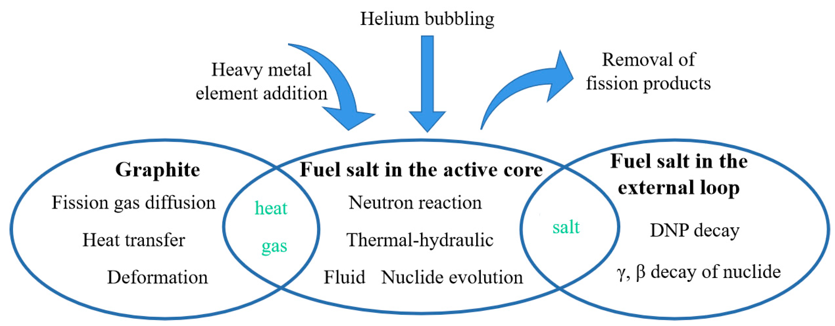
2.2. Main Operational and Physical Mechanisms of MSRs

Figure 2 demonstrates a typical graphite-moderated MSR system. This configuration can also represent the scenario of an MSFR, except for the free flow of fuel salt in the core, which is stronger in turbulence since the guidance offered by graphite tubes does not exist in the core. During core operation, the liquid fuel salt goes through the MSR core, where nuclear fission occurs, with the released heat absorbed by the molten salt. The heated fuel salt then flows to the heat exchangers, with the heat transferred to the secondary loop for electricity generation or other applications such as H2 production and sea water desalination. To enhance neutronic economy, one bypass flow is guided to a helium bubbling system, where the fission gases and sparingly soluble noble metal elements entrained in the helium bubbles, including Kr, Xe, Se, Nb, Mo, Tc, Te, etc., are removed by porous carbon absorbers. Meanwhile, helium is continuously bubbled to the core [50]. Another bypass leads to the reprocessing system for the online recycling of heavy metals (HMs) and for removing soluble fission products. Fluorination is first performed to recover isotopes of U, Np, and Pu in fluoride form. Part of the residual HMs are thereafter separated from the molten salt by a reductive extraction process and are then stored in a stockpile for several months, to let the 233Pa decay to 233U. Fluorination is performed again to collect the decayed 233U, part of which, together with other HMs (such as Np, Am, and Cm), depending on choice, are then returned to the core to maintain the core critical operation. The fluoride salt and thorium are finally recycled via distillation and electrodeposition, respectively, leaving fission products (FPs) for storage and disposal [7,51]. In a severe accident, the fuel salt will be discharged quickly into the fuel salt drain tanks by thawing the freeze valve, to mitigate the consequences of the accident.
The unique operational processes of MSRs, as discussed above, lead to more tight and complicated couplings among physical mechanisms, compared with the solid-fueled reactors, as presented in Figure 3. The liquid fuel makes neutronics and thermal hydraulics coupling tighter in MSRs. Thus, the temperature rise in the core of MSRs would be more rapid in accidents concerning reactivity insertion. The flowing of fuel salt, on the one hand, causes the decay heat to spread through the primary loop, influencing the profile of fuel salt temperature rise and distribution in an accident. On the other hand, it results in the delayed neutron precursor flowing out from the core, reducing the delayed neutron fraction of the core, and subsequently affecting the safety control. Furthermore, the flowing of fuel salt leads to the nuclides being entrained in the molten salt that is continuously circulating through the core, where the nuclides experience neutron flux irradiation and nuclide decay, and the external core loop, including the pipes, pumps, and heat exchangers, in which only nuclide decay occurs. The nuclide evolution law in MSRs is, hence, significantly different from that in the solid-fueled reactors. Our previous studies demonstrated that the concentration of 135Xe, one of the main core neutron poisons, is reduced by more than half when the flowing effect of fuel salt is considered [13]. Another neutron poison, 149Sm, also presents a different behavior from solid reactors in nuclide concentrations during core transience, under the condition of fuel salt flow, such as core power rising and a scram procedure [14].
Graphite-related issues, including graphite deformation, graphite heat transfer, and graphite permeation by the fission gases and fuel salt are also important physical mechanisms that should be considered. The graphite in the core acts as the moderator and also the predominant structural material. It must endure high neutron flux irradiation under high-temperature conditions. Lattice displacement occurs and is aggravated by burnup, which subsequently influences the strength of the extension, thermal expansion, Young’s modulus, etc. The dimension of graphite would experience a change with the burnup in such a way that it first shrinks and then expands, complying with the function of the influence of fast neutrons and core operating temperature. Studies conducted by ORNL in the 1960s demonstrated that graphite shrinkage in the core can reach around 4.5–7%Δ v/v [52]. This significant deformation of the graphite in the core will change both the neutronic performance, by affecting the neutron moderation capability, and the thermal-hydraulic performance, by influencing the flow field. Energy is deposited in the graphite due to neutron moderation and gamma irradiation. Removing this heat by the fuel salt forms a heat transfer mechanism between the graphite and the fuel salt. This is of importance to the thermal-hydraulic calculation and directly determines the graphite temperature. Fission gas and fuel salt penetration of the graphite is another important mechanism and is also a predictable event, due to the porous properties of graphite, significantly influencing the neutronic performance of the core. This mechanism is accompanied by helium bubbling, making the simulation more complicated.
Online refueling and reprocessing can be regarded as the external mechanisms that change the intrinsic burnup course, influencing the composition contained in the fuel salt and core reactivity. As fuel elements are added to the core, the concentrations of corresponding nuclides will increase abruptly, which subsequently changes the concentrations of their daughter nuclides. Online reprocessing is an inverse process of online refueling. Nuclides, including fission products/actinide nuclides, that are extracted online from the fuel salt would decrease the concentrations of the related nuclides.
The above mechanisms, derived from graphite, fuel salt, both in the active core and external loop, and the online refueling and reprocessing couple with each other, introducing great challenges in the physical simulation of MSRs.

3. Development of MSR Multi-Physics Coupling Models

As performed in solid-fueled reactors, MSR multi-physics coupling refers to coupling among neutronics, thermal hydraulics, burnup, and mechanics/materials, but meanwhile, this necessitates taking into account the unique physical mechanisms of MSRs, as shown in Figure 4. These are coupled via power and temperature distribution, and we must consider the loss of the delayed neutron precursor due to the flowing of fuel salt. Neutronics, meanwhile, couples with the burnup by providing a neutron flux, while obtaining the nuclide composition from burnup. The mechanisms of fuel flowing, online refueling and reprocessing, and helium bubbling, which derail the nuclide evolution from its intrinsic course, should be taken into account in this coupling. Neutronics couple with the mechanism of the graphite cell through graphite deformation. Thermal hydraulics couples burnup and the graphite cell by offering flow-field and temperature distribution, while the graphite cell couples with burnup via nuclide permeation and evolution in the graphite. Until now, many studies have been conducted on N-TH coupling, N-TH-BN (burnup) coupling, and N-TH-G (graphite cell) coupling, but a complete multi-physics coupling, i.e., a N-TH-BN-G coupling, has not been reported. Hence, more efforts are needed for the development of a multi-physics coupling model (MPCM). The rest of this section gives an overview of the historical and current status of MPCM development, aiming to outline the problems and challenges of MPCMs.

3.1. N-TH Coupling

Since MSRs were proposed by ORNL in the 1960s, remarkable progress has been made in the study of MSR N-TH coupling. Models with dimensionality extending from 0D (0-Dimension) to 3D (3-Dimension) have been proposed sequentially, with the modeling accuracy significantly improved. Table 1 gives an overview of the N-TH coupling models.

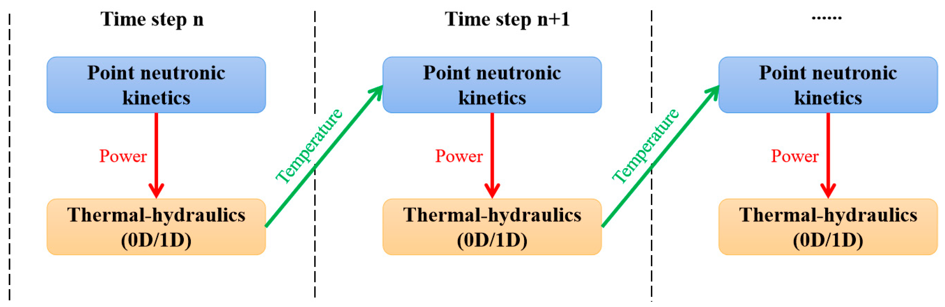
3.1.1. Point Neutronic Kinetics (0-Dimension N) Coupling with Lumped TH Parameters (0-Dimension/1-Dimension/2-Dimension TH)

A point neutronic kinetics model is widely used in the field of reactor safety analysis due to its significant advantages in terms of computation cost. It describes the time behavior of a reactor system with point neutronic kinetics equations, in which the spatial shape of the neutron flux is assumed to be unchanged with time:
d n ( t ) d t = ρ ( t ) β Λ n ( t ) + i = 1 N λ i C i ( t )  
d C i ( t ) d t = β i Λ n ( t ) - λ i C i ( t )  
where ρ is the core reactivity, which is determined by the temperatures of the fuel, coolant and moderator; β is the effective fraction of delayed neutrons; Λ is the neutron generation lifetime; λ i is the DNP decay constant of family i;  β i is the delayed neutron fraction of family i; N is the total number of DNP family, which is usually set to be six. In Equations (1) and (2), n ( t ) is always written as power P(t), since the core power is linearly related to the magnitude of the neutron flux. In addition, a term correlating C i ( t ) with the fuel salt residence time in the core and external loop should be added in Equation (2) to account for the effect of DNP loss, caused by the flowing of fuel salt in an MSR.
Usually, a loose coupling scheme is adopted for the coupling of the point neutronic kinetics model with a TH model, as presented in Figure 5. The point neutronic kinetics model provides power to the thermal-hydraulic model during one time step, then the thermal-hydraulic model feeds back the temperature distribution to the point neutronic kinetics model at the next step, and so forth until the preset time steps come to an end. This coupling scheme significantly reduces the computational cost, compared with the tight coupling scheme, in which the iteration between neutronics and thermal hydraulics is continued over one step until it converges.
A point neutronic kinetics model was adopted by ORNL for MSR calculation in the 1960s. It was coupled with the lumped parameters of the TH model, forming the first MSR dynamic calculation tool, MURGATROYD [17], in which the same differential equations of point neutronic kinetics model as are used in solid fuel reactors are adopted, i.e., Equations (1) and (2), and the flow effect of fuel salt on delayed neutron fraction is simply considered by revising the fraction of delayed neutrons of the ith group, v i , in the core:
v i   = 1 1 e λ i τ C λ i τ C · 1 e λ i τ L 1 e λ i ( τ C + τ L )  
where τ C and τ L are the residence time of fuel salt in the core and external loop, respectively, which are calculated based on the constant neutron flux and slug flow under the steady state of the core. Therefore, this simple revision cannot accurately describe the time behavior of the delayed neutron in the core, especially in the case of transients and accidents. The TH model of MURGATROYD divides the core into a fuel salt block and a graphite block. The heat transfer between these two blocks is calculated. The coupling between the point neutronic kinetics model and thermal-hydraulic model is then realized by feeding back the temperature of fuel salt and graphite:
k eff = 1 + ρ i n + b t | k eff T f | ( T f T f 0 ) | k eff T g |   ( T g T g 0 )
where k eff is the effective multiplication of the core and is related to the core reactivity ρ in Equation (1), with a function of ρ = ( k eff − 1)/ k eff ; ρ i n is the initial step reactivity input, b is the initial ramp reactivity input; T f   and T g are the temperatures of fuel salt and graphite, respectively; T f 0 and T g 0 are the temperatures of fuel salt and graphite in the steady state, respectively.
In 1971, in order to analyze the safety performance of MSBR, the dynamic calculation model was improved in terms of both the aspects of neutronics and thermal hydraulics, with the ability to model the transient behavior of the whole reactor system. The improved model accounts for the flowing effect by adding the terms of the delayed neutron precursor flowing out from the core (the third term on the right side of Equation (5)) and entering the core from the external loop (the fourth term on the right side of Equation (5)) to the delayed neutron precursor time-dependent differential equation:
d C i ( t ) d t = β i Λ P ( t ) λ i C i ( t ) 1 τ C C i ( t ) + e λ i τ L τ C C i ( t ) ( t τ L ) .
However, the DNPs are divided into only two groups in the improved model. The TH lumped-parameter model was extended from the core to the whole reactor system by using the nodal method, as shown in Figure 6. The graphite and fuel salt in the core are modeled to be several nodal blocks, based on which heat transfer between graphite and fuel salt and heat delivery via fuel salt flowing was simulated. The temperatures of the fuel salt and graphite in the core can then be obtained by averaging the temperature of the nodal blocks. In the same way, the temperatures of the working fluid in the secondary loop and energy conversion system were calculated, in terms of time. The control system was modeled by a set of equations describing the adjustment of the flow rate and control rod behavior to control the steam temperature and reactor outlet temperature during transient events [53]. It being capable of simulating the transient behavior of the whole system is one main merit of this improved model, which has been widely referenced by the subsequent MSR dynamic codes.
The neutronics aspect of the MSR point dynamic model was improved by Lapenta et al. in 2001 [20]. Neutrons in the different core spatial positions for different energy groups will induce nuclear fission with different probabilities since nuclear fission cross-sections vary with neutron energy and a strong neutron leakage exists near the boundary of the core. Neutrons in the center of the core usually have higher importance than those in the peripheral core region, in terms of power generation. This neutron importance can be described by the adjoint neutron flux, which can be calculated by solving the adjoint neutron flux conservation differential equations. To account for the importance of fission neutrons, including both prompt and delayed neutrons, a normalization factor (F) was introduced to amend the parameters involved in the point neutronic kinetics model:
F = i = 1 R n = 1 G Φ n | χ i , n λ i C i , 0 + ( 1 β ) n = 1 G g = 1 G Φ n | χ n ( ν Σ f ) g , 0 Φ g , 0
where Φ n is the adjoint neutron flux; R and G are the groups of the delayed neutron precursor and neutron flux, respectively; χ n and χ i ,   n indicate the probability of fission neutrons in the n-th energy group and neutrons released from the i-th delayed neutron precursor group in the n-th energy group, respectively; ν is the average neutrons generated in nuclear fission. Taking the DNP of family i as an example, the parameters of the point kinetics model are amended thus:
β ˜ i = 1 F n = 1 G Φ n | χ i , n λ i C i , 0 .
In 2004 [16], a quasi-static method was employed to account for the spatial shape change of the neutron density and DNP concentration with time in the point neutronic kinetics model. The quasi-static method adopts the classic factorization projection scheme to solve the time-dependent neutron and adjoint neutron flux equations. Weighting vectors, in terms of neutron flux and delayed neutron precursor concentration, are obtained to correct the parameters during an interval step time, Δt. In this way, transients with a distortion of spatial neutron density shape and delayed precursor concentration can be simulated by using the point kinetics model, but this improvement is limited to those cases with a large change in neutron density shape.
In subsequent studies of MSR transient calculations associated with the point dynamic model, more attention was paid to the development of thermal-hydraulic models. A single-channel model (1D model) for thermal-hydraulic calculation was developed to couple point neutronic kinetics model by Auwerda in 2007 [54], Suzuki et al. in 2008 [55], Guo et al. in 2013 [56], and Cai et al. in 2014 [57]. It was then extended to a multi-channel model (2D model) by Shi et al. in 2016, via improving RELAP5, which is a point dynamic code designed for solid-fueled reactors and has the ability to perform system transient analysis by using the nodal method. The loss of a delayed neutron precursor due to the flowing of fuel salt was modeled by revising the DNP differential equations, as expressed in Equation (5) [58].
From the above, it can be concluded that point dynamic models have played an important role in MSR safety analysis and have attracted attention worldwide, even in recent years. Thermal-hydraulic models with 0–2 dimensions were also developed, and some efforts have been made to address the drawbacks when describing the shape change of the neutron flux in the core. Nevertheless, great errors and uncertainties would be inevitably introduced for the analysis of accidents with a large and abrupt shape change in terms of neutron flux and local reactivity insertion.

3.1.2. The 1-Dimension Neutronics Coupling with 1-Dimension Thermal Hydraulics

In parallel with the development of the MSR point dynamic model in the years after 2000, a 1D dynamic model was proposed with the aim of improving the accuracy of transient analysis. Two energy groups, i.e., the thermal and fast neutron energy groups, are generally adopted in the 1D time-dependent neutronic diffusion equations:
1 ν 1 Φ 1 ( z ,   t ) t = z ( D 1 Φ 1 ( z ,   t ) z ) + ( 1 β ) [ ν 1 Σ f 1 ( z ) Φ 1 ( z ,   t ) + ν 2 Σ f 2 ( z ) Φ 2 ( z ,   t ) ] [ Σ a 1 ( z ) + Σ s ( z ) + D 1 B 2 ] Φ 1 ( z ,   t ) + i = 1 M λ i C i ( z ,   t )
1 ν 2 Φ 2 ( z ,   t ) t = z ( D 2 Φ 2 ( z ,   t ) z ) [ Σ a 2 ( z ) + D 2 B 2 ] Φ 2 ( z ,   t ) + Σ s ( z ) Φ 1 ( z ,   t )
C i ( z ,   t ) t = β i [ ν 1 Σ f 1 ( z ) Φ 1 ( z ,   t ) + ν 2 Σ f 2 ( z ) Φ 2 ( z ,   t ) ] λ i C i ( z ,   t ) V ( z ,   t ) C i z , i = 1 , , M
where the subscripts “1” and “2” indicate “fast” and “thermal”, respectively; Φ is the neutron flux; ν is the speed of neutrons; D is the neutron diffusion coefficient; Σ f is the macroscopic fission cross-section; Σ a is the macroscopic absorption fission cross-section; Σ s is the macroscopic scattering cross-section from the fast group to the thermal group; V is the flow speed of the molten salt in the core; M is the groups of delayed neutrons, which is generally set to be six. The terms in the right side of Equation (8) represent the time change of the fast neutron flux caused by neutron diffusion, prompt neutron (thermal and fast) fission, neutron absorption, neutron scattering, neutron leakage, and delayed neutron fission, respectively. Equation (9) describes the time change of the thermal neutron flux, in terms of neutron diffusion, neutron absorption, neutron leakage, and neutron scattering from the fast neutrons. The time change of the delayed neutron precursor is specified by the neutron groups, while the axial position is as expressed in Equation (10). With this model, this z-axial shape change of neutron density under transients and accidents can be simulated.
The 1D neutron kinetic model was generally coupled with a single-channel model of thermal hydraulics. Cinsf1D (Cinétique pour réacteur à sels fondus, 1D) proposed by Lecarpentier et al. in 2003 is one typical code of this model [59]. It adopts a time-dependent two-energy-group diffusion theory, as shown in Equations (8)–(10), for neutronic calculation. The effective neutronic cross-sections associated with the temperatures of the molten salt and graphite were prepared in advance by performing the neutronic transport calculation of fuel cells. The core was modeled as a single channel in which the graphite prism was treated as a cylinder, with the fuel salt located in the centerline for thermal-hydraulic calculation. The time-dependent equations, in terms of axial fuel salt temperature, graphite temperature, and heat transfer between them were solved to feed back the core temperature distribution to the neutronics calculation [59]:
T s ( z ,   t ) t = P f ( z ,   t ) π R 2 ρ s c s V ( t )   T s ( z ,   t ) z 2 h R ρ s c s [ T s ( z ,   t ) - T g ( r ,   z ,   t ) ]
T g ( r , z ,   t ) t = 2 h R ρ s c s [ T s ( z ,   t ) T g ( r ,   z ,   t ) ]
ρ g c g λ g T g ( r ,   z , t ) t = 1 r T g ( r , z , t ) r + 2 T g ( r , z , t ) r 2
where the subscripts “s” and “g” indicate fuel salt and graphite, respectively; P f is the power contained in the fuel salt; R is the radius of the graphite cylinder; ρ is the fuel salt density; c is the specific heat capacity; h is the heat convection coefficient between fuel salt and graphite; λ is the thermal conductivity of graphite. Another MSR 1D N-TH coupling dynamic calculation code reported in the open literature is DYN1D-MSR, developed by Křepel et al. in 2005 [60]. The main improvements of this code compared with Cinsf1D are in terms of thermal-hydraulic calculation. In DYN1D-MSR, the graphite moderator in the core is divided into several segments to more accurately model the temperature distribution of the graphite, while the mass and energy balance of the fuel salt are taken into account. Compared with the point dynamic model, the 1D dynamic model is able to capture the axial shape change of neutron density. However, significant simplification in both neutronics and thermal-hydraulic calculation would still introduce many errors and uncertainties into the simulation, leading to very limited efforts made on the development of this 1D N-TH coupling dynamic model.

3.1.3. 2-Dimension Neutronics Coupling with 2-Dimension Thermal Hydraulics

Coupling the 2D neutronic kinetics model with the 2D thermal-hydraulics model can accurately simulate the nuclear reactor transient events that occur in those types of MSRs that have a symmetric geometry in the X-Y plane, e.g., MSFR and MOSART. The differential equations of neutronic diffusion involved in the model have similar forms, with the scenario of 1D expressed in Equations (8)–(10), except for the terms associated with the neutron diffusion coefficient ( D ) and the flow velocity of fuel salt ( V ), which should be extended to the R-Z dimensions. Relatively large differences exist in the thermal-hydraulic model, compared with the scenario of the 1D model. In the 2D TH models, the mass, momentum, and energy balance of the fuel salt should be taken into account, as described in the following equations:
ρ s ( r ,   z ,   t ) t + · [ ρ s ( r ,   z ,   t ) V ( r , z , t ) ] = 0
[ ρ s ( r ,   z ,   t ) V ( r , z , t ) ] t + · [ ρ s ( r ,   z ,   t ) V 2 ( r , z , t ) ] = P ( r , z , t ) + · τ ( r , z , t )
[ ρ s ( r ,   z ,   t ) h ( r , z , t ) ] t + · [ ρ s ( r ,   z ,   t ) h ( r , z , t ) V ( r , z , t ) ] = Q
where τ is the stress tensor caused by friction and gravity, h is the energy enthalpy of fuel salt, P is the pressure drop of fuel salt, and Q is the energy produced in the fuel salt. In addition, the vorticity of fuel salt should be considered for the TH calculation in fast MSRs, while the heat transfer between fuel salt and the moderator should be taken into account for thermal MSRs.
To realize the coupling between neutronics and thermal hydraulics in the R-Z dimensions, different methods/schemes were proposed. In the 2D dynamic calculation model developed by Yamamoto et al. in 2006, the time-spatial dependent equations involved in the neutronics and thermal-hydraulics calculations were firstly discretized, based on the control volume and implicit methods. These discretized equations were then solved using Patankar’s SIMPLE algorithm and relaxation algorithm [65]. In the same year, Wang et al. made an improvement on a traditional 2D dynamic code, SIMMER-III, which was originally developed for the safety assessment of sodium-cooled fast reactors, to account for the effects of fuel flow. This code couples N and TH externally, for which the transient neutron flux distribution is calculated with the improved quasi-static method, and temperature distribution is evaluated using the Eulerian fluid-dynamics model [62]. In 2008, Nicolino et al. realized 2D N-TH coupling via solving the equations of neutronic diffusion and full-core computational fluid dynamics together, using a rigorous and fully implicit approach Jacobian Free Newton Krylov (JFNK) algorithm [63]. In 2009, Zhang et al. developed a 2D dynamic simulation code by using the alternating direction implicit TDMA algorithm to solve the equations of N and TH in an internal coupling approach, but the TH calculation only took into account the heat transfer of fuel salt [61]. In 2011, Cammi et al. applied a segregated solver of the finite element method, using quadratic Lagrangian elements to solve the overall equation systems of the reactor, based on the multi-physics coupling platform, COMSOL. This multi-physics method can take into account the turbulence and buoyancy effects, provide detailed information on the fields of temperature and velocity and is suitable for the simulation of MSRs with complex geometry [64]. Overall, 2D N-TH coupling offers an improvement in terms of accuracy in safety analysis but being unable to accurately simulate the local transients/accidents, or transients/accidents occurring in MSRs with an asymmetric core geometry, limits its development.

3.1.4. 3-Dimension Neutronics Coupling with 2-Dimension/3-Dimension Thermal Hydraulics

As computing technologies constantly improve, the coupling of 3D neutronics with thermal hydraulics has attracted growing attention from MSR dynamics analysis. In 2007, Krepel et al. developed a 3D MSR dynamic code, termed DYN3D-MSR, by improving the light water reactor dynamic code, DYN3D. The 3D neutron diffusion equations were split into three 1D equations and solved using the nodal expansion method. A multi-channel thermal-hydraulic model was adopted to externally couple with the 3D neutronic model. With this developed code, channel-wise transients were successfully simulated. However, the heat insulation treatment on the edge of fuel channels in the multi-channel model made DYN3D fail to simulate the accidents that involve heat transfer between the adjacent channels, e.g., an accident due to a blockage in the fuel channel [66]. In 2009, Kophazi et al. developed a similar 3D dynamic code by coupling the 3D neutronic code, DALTON, and the in-house thermal-hydraulic code, THERM. This code is capable of modeling heat conduction in the moderators of graphite over the entire core, using the conjugate gradient method to solve the related equations. Every fuel channel in the core can, hence, be connected thermally through the graphite [69]. The multi-channel model was also adopted by Zhang et al. in 2015 [67] and by Cui et al. in 2022 to couple their respective in-house 3D neutronic diffusion solvers externally, forming the 3D dynamic analysis codes of MOREL and TMSR-3D, respectively. In these two codes, however, heat transfer between two adjacent graphite cells was not considered, as in DYN3D-MSR [68].
In the work of Nagy et al. in 2014, an in-house thermal-hydraulic model using the porous medium method was applied. In this TH model, the equations of fuel salt by Navier-Stokes, fuel salt temperature, and graphite temperature are solved to evaluate the change in temperature distribution and flow field. This couples with DALTON to perform dynamic analysis of graphite-moderated MSRs [70]. Based on the same neutronic code, DALTON, in 2012, Linden made a couple with an in-house CFD program, HEAT, in which the RANS (Reynolds-averaged Navier-Stokes) equation was solved with k − ε model, to perform dynamic analysis of MSFR [23]. In 2020, Tiberga developed a high-fidelity multi-physics simulation tool by coupling the in-house CFD parallel solver DGFlows and the neutron transport code PHANTON-SN to accurately evaluate the behavior of the physical mechanisms of neutron transport, fluid flow, and heat transfer in a fast-spectrum MSR under transients/accidents [24].
In addition, efforts have been also made to realize the N-TH coupling on multi-physics platforms, to take advantage of advanced computing techniques. Based on the multi-physics coupling platform OpenFOAM, in the work of Cammi et al. in 2014, the differential equations of 3D neutron diffusion and the RANS model for mass and momentum conservation were solved together, via Picard iterations [21]. MOOSE (multiphysics object-oriented simulation environment) is a parallel computational framework oriented for solving the nonlinear equations of coupled systems by using the JFNK method and allows researchers to easily implement advanced finite element methods and to use niche basis functions. In 2017, Ridley developed a high-fidelity dynamic analysis model for MSRE by using one application of MOOSE, Moltres, to solve the governing equations of neutron diffusion and thermal hydraulics [25]. Later, in 2022, Yang et al. made a coupling of the neutron transport code PROTEUS-NODAL with the system thermal-hydraulic calculation code SAM, based on MOOSE [72]. COMSOL is a finite element solver and multiphysics simulation software that is oriented for the solution of partial differential equations of coupled systems. With COMSOL, in 2020, Bajpai et al. carried out a coupling of neutronics with thermal hydraulics by using a two-phase Euler-Euler model to evaluate the influence of helium bubbling [71].

3.1.5. N-TH Coupling for Steady-State Analysis

The steady state of the core is one important state necessitating deep analysis for core design. It is generally regarded as a condition that the performances of the reactor system are unchanged with time. The terms associated with differential time in the partial differential equations of neutron diffusion/transport and thermal hydraulics can be set as zero. The solution processes for the coupling calculation are, hence, significantly simplified. Most importantly, the coupling of N-TH in the dimension of time is removed, which substantially reduces the calculation cost and allows for applying more time-cost codes of neutronics and thermal hydraulics, such as Monte Carlo codes and CFD, to perform accurate core modeling and calculation. As early as 1962, Engel et al. made an N-TH coupling in 2D for MSRE steady-state analysis by using an analytical solution [73]. In 2008, Zhang et al. conducted a coupling of the deterministic neutron code, Dragon, with a multi-channel thermal-hydraulic model to perform 3D N-TH calculation for thermal MSRs [74]. Based on the Monte Carlo code MCNP, in 2013, Guo et al. [75] and Laureau [76] carried out a coupling with a multi-channel thermal-hydraulic model and CFD in 3D for a steady-state analysis of thermal MSRs and MSFR, respectively. In 2020, Deng et al. conducted a steady state analysis of MSFR by coupling the open-source codes of OpenMC (3D neutronics calculation) and OpenFOAM (3D thermal-hydraulic calculation) to accurately analyze the distribution of temperature, power, and flow field in the core [77].

3.2. N-TH-BN Coupling Development

Fuel burnup is a measure of how much energy is extracted from fuel, reflecting the fuel depletion and the consequent changes in fuel composition. One main task of fuel burnup analysis is to accurately evaluate the time evolution of all nuclides of fuel in the core, which is also called burnup calculation. Up until now, the calculation of burnup coupling with neutronics has been extensively studied by considering the above MSR unique mechanisms, while thermal hydraulics is rarely coupled, which necessitates more efforts in terms of future N-TH-BN study. The main features of current N-TH-BN coupling models are summarized in Table 2.

3.2.1. The N-TH-BN Coupling Model, Considering Online Refueling and Reprocessing

In a reactor core, the time evolution of the isotopes of fuel under a neutron flux can be generally described using the Bateman equations:
d N i d t = j N j Φ Δ σ j i j N i Φ Δ σ i j + j N j λ j Δ σ j i N i λ i
where N is the nuclide concentration, σ is the neutron reaction cross-section associated with temperature, and λ is the nuclide decay constant. In the equations, nuclide transmutation under neutron flux Φ (the first and second term on the right side) and nuclide decay (the third and fourth term on the right side) are considered. To solve Equation (17), neutron flux Φ and the temperature of the fuel should be provided in advance; in turn, the change of nuclide concentration would influence the neutron flux Φ and temperature distribution, and so forth. Therefore, a coupling calculation among them is required [78,79,80]. For MSRs, the nuclides in the core that undergo online refueling and reprocessing would deviate somewhat from the law described in Equation (17). As a result, the traditional burnup calculation tools for reactors with solid fuel are no longer suitable for MSRs.
In the 1960s, to evaluate the fuel cycle performance of the circulating fuel reactors, ORNL developed a code, ROD, which couples the neutronics and burnup calculation while taking no account of thermal hydraulics. The time change of nuclide concentration in MSRs is described by two equations:
V j d N i j d t = Q i j f + R i j + F i j + T i j + D i j N i j ( t i j + d i j + q i j r i j ) = 0
[ N i j s N i j s 1 ] ν i k C i j k f = i j k N i j s 1 C i j k a i j k N i j s 1 C i j k f ν i
where V j is the volume of stream j; Q i j f is the feed rate of nuclide i into stream j; R i j is the production rate of nuclide i in stream j, due to recycling from other streams; F i j is the production rate of fission fragment i in stream j; T i j and D i j indicate the production rate of nuclide i in stream j due to neutron absorption and the radioactive decay of other nuclides, respectively; t i j ,   d i j   and q i j denote the rate coefficient for the loss of nuclide i in stream j because of neutron capture, radioactive decay, and processing removal, respectively; r i j is the production rate coefficient of nuclide i in stream j, resulting from recycling from stream j; N i j s is the concentration of nuclide i in stream j at iteration s; ν i represents the neutrons produced per fission in nuclide i; C i j k f and C i j k a indicate the fission and absorption reaction rate coefficient of nuclide i in stream j in region k, respectively. Equation (22) is an improved Bateman equation, considering online feeding and reprocessing, while Equation (23) is the conservation equation to overcome the deficiency/excess of neutron production at iteration s-1 by adding/removing fissile materials in iteration s. By coupling the 2D neutron diffusion calculation performed by the MODRIC module from ROD, the above two equations were iteratively solved by module ERC of ROD to realize the equilibrium nuclide concentration calculation [81].
In 2005, Nuttin et al. introduced a fictive time-decay constant, λ e , to model the fuel salt reprocessing in nuclide evolution calculation, by assuming that the amount of nuclide i extracted from inventory Ni during dt is proportional to the quantity Ni × dt T r , with extraction efficiency ε e :
d N i = N i d t T r ε e = N i λ e d t ,   λ e = ε e T r
where T r is the time during which the fuel salt in the primary loop is reprocessed once. The nuclide evolution in MSRs can, then, be written as:
d N i d t = j N j Φ σ j i j N i Φ σ i j + j N j λ j σ j i N i λ i N i λ e + F i f e d
where F i f e d refers to nuclide refueling. This equation is solved based on the neutron flux provided by MCNP to perform the nuclide evolution calculation [7].
The above MSR burnup calculation method was widely adopted in the subsequent studies of MSR fuel cycle modeling. In 2008, to evaluate the fuel element compositions contained in the molten salt in a state of equilibrium, Becker et al. developed a code, MOCUP, by coupling MCNP5 and ORIGEN2, with the former used for neutronic calculation while the latter was used for nuclide evolution calculation [82]. Based on the same neutronic code, MCNP5, in 2011, Merle-Lucotte et al. made a coupling with an in-house nuclide evolution code REM for the burnup calculation of MSFR [83]. This coupled model was improved by Doligez et al. in 2014, to assess nuclide evolution in the reprocessing unit and fission gas storage beside it in the core [84]. SCALE and SERPENT are two other Monte Carlo neutronic calculation codes that are usually taken for N-BN coupling calculation. In 2012, Sheu et al. developed a special sequence based on SCALE6 for the N-BN calculation, which, however, can only account for batch reprocessing and the refueling of MSRs [85]. In the special MSR reprocessing sequence (MSR-RS) developed by Zou et al. in 2015, based on SCALE6, the function was extended to cover the modeling of online reprocessing [86]. In 2013, Aufiero et al. made an improvement to the SERPENT code to perform N-BN coupling calculation, considering reprocessing and refueling in MSRs [87]. Apart from the Monte Carlo method, deterministic neutronic methods were also reported as being used. In 2013, Fiorina et al. realized the N-BN coupling calculation for MSRs by improving a deterministic code, ERANOS [88].
In the above studies, the nuclide evolution calculation took no account of the thermal hydraulics coupling and might be significantly mis-estimated. To address these issues, recently, some efforts have been made regarding the N-BN-TH coupling calculation. In 2013, to accurately evaluate the nuclide evolution in an MSFR, Frima added a new term related to flow velocity, · [ u i ( r , t ) N i ( r , t ) ] , to the space-time-dependent nuclide evolution equations, which is an extension of Equation (21), to account for flow effect. The in-house code, LOWFAT, was taken to perform the multi-group neutron diffusion calculation, while the thermal hydraulic calculation was carried out with the in-house code HEAT, via solving the Reynolds averaged Navier-Stokes (RANS) equations to model the turbulent flow [89]. In 2019, Graham et al. developed a multi-physics model in which the neutronics, thermal hydraulics, and burnup are coupled via the flow velocity and temperature, based on the virtual environment for reactor applications (VERA) [90]. The flowing effect and FPs deposited on the surface of structure materials were considered in the nuclide evolution equations (highlighted in bold in the following equation):
d N i ( r , t ) d t = j N j ( r , t ) Φ ( r , E ) σ j i ( T , E ) j N j ( r , t ) Φ ( r , E ) σ i j ( T , E ) + j N j ( r , t ) λ j σ j i ( T , E ) N i ( r , t ) λ i N i λ e + F i f e d · [ u i ( r , t ) N i ( r , t ) ] · J i ( r , T )
The neutronics calculation was performed by a module, MPACT, using a method of characteristics (MOC), while the thermal-hydraulic calculation was conducted via a subchannel module CTF. In 2022, Ronco et al. conducted an in-depth study on the modeling of FP deposit on the surface of the structure material by coupling neutronics and thermal hydraulics, considering FPs turbulent diffusion D e f f [27,91]:
d J i d t + · ( u i J i ) = · ( D e f f J i ) λ i J i + y i g Σ f , g Φ g
where y i is the fission yield, Σ f , g is the fission cross-section, and g is the energy group.
In general, the time step for the above nuclide evolution calculation is in a magnitude of days, while the time scale of transient analysis is in a magnitude of a second. To realize transient analysis covering the whole fuel life cycle, in 2022 Pathirana et al. proposed an MSR dynamics model which is dependent on depletion. The simulation time was factorized into transient time and depletion time. The depletion-dependent data were pre-calculated before the transient evaluation. The transient calculation was then executed at a certain time, using the constant depletion-dependent parameters [28].

3.2.2. N-TH-BN Coupling Model with Considering Helium Bubbling

As introduced in Section 2.2, helium bubbling functions as a way to remove the sparingly soluble FPs, including fission gases and noble metal elements, and subsequently influenced the evolution behavior of these nuclides. 135Xe is one type of fission gas nuclides having a large neutron absorption cross-section and is regarded as a major neutron poison in the core. Modeling of its evolution behavior has been extensively studied by gradually coupling the neutronics, thermal hydraulics, and helium bubbling. With a given temperature and neutron flux, a simple model considering several mechanisms, including the 135Xe interaction between fuel salt and graphite, 135Xe decay in the external loop, and 135Xe stripping in the pump bowl, was developed by ORNL in 1962 [92,93]. In 1967, this model was improved by including all of the important and potentially important behavior mechanisms, encompassing the 135Xe generation rate, the decay rate in the salt, the burnup rate in the salt, the stripping rate, the migration rate to the graphite, and the migration rate to the circulating bubbles. The core was divided into 72 annular rings to accurately assess the 135Xe behavior in the graphite. Many of the gas-transport constants involved in the governing equations of 135Xe behavior were inferred from a pre-operational experiment run in the MSRE, with 85Kr as the tracer [94]. This calculation model can reproduce reasonably well the observed core poisoning of 135Xe at a steady state, but it could not adequately describe its transient behavior. In front of this background, a more elaborate mathematical model that specifically described the behavior of 135Xe in the primary loop and considered the cover-gas solubility was developed by ORNL in 1971. As demonstrated in Figure 7, the behavior of 135Xe is realistically simulated by dividing the primary loop into four calculation modules, along the flow of fuel salt. In each calculation module, the mechanisms of 135Xe generation, disappearance, and interaction among gas bubbles, liquid fuel salt, and graphite (only for the core calculation module) were taken into account. A total of 31 time-related differential equations were applied to accurately model the transient behavior of 135Xe in four calculation modules, as well as the connections among them [95]. However, in this detailed mathematical model, the values required for the parameters of xenon mass transport were significantly different from the predicted values; it failed to describe the transient observations in MSRE adequately. Hence, additional investigations would be needed to further elucidate the behavior of 135Xe in MSRs. In 2020, to accurately simulate the internal behavior of 135Xe in the graphite, Price et al. made an improvement to the model by adding a cylindrical diffusion equation for 135Xe [96].
In the above 135Xe evolution models, the neutron flux and temperature distribution are given in advance without coupling with N-TH, which might misestimate the positioning of 135Xe in the core. In 2017, Wu et al. analytically derived the time-dependent equations of the nuclide evolution of 135Xe contained in the flowing fuel salt by considering the stripping rate of helium bubbling. The neutron flux, calculated by a deterministic code (CITATION), was coupled to solve the nuclide evolution equations and to evaluate the behavior of 135Xe regarding steady-state and transients [13,97]. In 2022, Caruggi et al. extended their previous OpenFOAM-based N-TH coupling model to evaluate the behavior of gaseous fission products in an MSFR [26]. The Euler-Euler solver for this two-phase calculation was employed to solve the governing equations that describe the mass exchange between bubbles and fuel salt. Besides this, the mechanisms of fission gas production resulting from fission, consumption due to neutron absorption, and removal by the off-gas system were modeled by coupling with N-TH:
S X e α m [ λ d e c + n ( σ c , n Φ n ) ] C X e ,   m + d M X e ,   m d t = α m C X e ,   m t + · ( α m u m C X e ,   m ) · [ α m u m S c m ( C X e ,   m ρ m ) ]
α g λ d e c C X e ,   g + d M X e ,   g d t = α g C X e ,   g t + · ( α g u g C X e ,   g ) · [ α g u g S c g ( C X e ,   g ρ g ) ]
d M X e ,   m d t = d M X e ,   g d t = 6 α g Sh d b 2 D m ( H C X e ,   g C X e ,   m )
S X e = y X e m m o l N A v n ( Σ f , n Φ n )
C X e t = y X e n ( Σ f , n Φ n ) C X e n ( Σ a , n Φ n ) ( λ d e c + λ b u b ) C X e
where the subscript m and g indicate the molten salt and gas, respectively; α is the interfacial area of exchange per unit volume; C X e is the concentration of 135Xe; d M X e d t denotes the mass transfer of 135Xe to or from the molten salt/gas; S c is the dimensionless Schmidt number; S h is the Sherwood number; D is the diffusivity coefficient; S X e is the production of 135Xe, resulting from fission; m m o l is the molar mass of 135Xe; N A v is the Avogadro number; λ b u b is the fictive time decay constant resulting from helium bubbling. Equations (24) and (25) describe the behavior of 135Xe in the molten salt fuel and helium bubbles, respectively. Equation (26) models the interaction of 135Xe between two phases. Equation (28) evaluates the time evolution of 135Xe, considering helium bubbling. In the same year, Taylor et al. carried out a similar study based on the multi-physic platform VERA by using the liquid-gas model. Neutron flux, temperature distribution, and fluid-flowing field were provided by the N-TH calculation for simulating fission gas behavior. Both the above two models, however, neglect the migration of 135Xe in the graphite, which necessitates an in-depth study in the future [98].
The evolution behaviors of noble metal fission products are significantly affected by helium bubbling. In 2021, Walker et al. developed a coupled NM (noble metal)-helium bubble model to simulate the behaviors of NM transport, deposition, and extraction. According to the behaviors of NM elements in the primary loop, the insoluble NM species were split into four categories: species dissolved in the bulk liquid, species deposited on a stationary structural surface of the loop, species transported either on the surface of or in helium bubbles and species accumulated in the pump bowl. For each sub-species, a governing differential equation was set up with respect to time, i.e., advective mass transport, due to a velocity field, source, or sink terms resulting from nuclide decay and deposit, and mass transfer terms among sub-species. These equations for all the species were solved by coupling the thermal-hydraulic calculation (CTF), while using a given neutron flux, which can be improved in the future [99].
Table 2. Development status of the N-TH-BN coupling models.
Codes/Developers/PlatformsN ModelTH ModelBurnup Model
Nuclide EvolutionReprocessingRefuelingHelium Bubbling
ROD, 1962 [81]2D diffusionGiven temperatureEquilibriumRemoval rate Feed rate-
ORNL, 1960s–1970s [92,93,94]Given neutron fluxGiven temperature135Xe time-step evolution--135Xe migration among fuel salt, graphite and bubble
Nuttin et al., 2005 [7]Monte CarloGiven temperatureTime-stepFictive time decay constantFeed rate Fictive time decay constant for fission gas and NM removal
MOCUP, 2008 [82]Monte CarloGiven temperatureEquilibriumFictive time decay constantFeed rateFictive time decay constant for fission gas and NM removal
Sheu et al., 2012 [85]Monte CarloGiven temperatureTime-step100% removal efficiencyFeed rate100% removal efficiency for fission gas and NM removal
Improved ERANOS, 2013 [88]3D diffusionGiven temperatureEquilibriumFictive time decay constantFeed rate-
Frima, 2013 [89]3D diffusionCFDTime-stepFictive time decay constantFeed rate-
Improved SERPENT-2, 2013 [87]Monte CarloGiven temperatureTime-stepFictive time decay constantFeed rateFictive time decay constant for fission gas and NM removal
Doligez et al., 2014 [84]Monte CarloGiven temperatureTime-stepFictive time decay constant, accounting for nuclide evolution in reprocessing unit and storageFeed rateFictive time decay constant for fission gas and NM removal
MSR-RS, 2015 [86]Monte CarloGiven temperatureTime-stepFictive time decay constantFeed rateFictive time decay constant for fission gas and NM removal
Wu et al., 2017 [13,97]3D diffusionGiven temperature135Xe time-step evolution--135Xe removal rate
VERA, 2019 [90]3D neutron transportSub-channelTime-step, accounting for interaction of each nuclide with system componentsRemoval rate Feed rateRemoval rate for fission gases and NMs
Price et al., 2020 [95,96]Given neutron flux Given temperature135Xe time-step evolution--135Xe migration among fuel salt, graphite and bubble, accounting for 135Xe diffusion in the graphite
Walker, et al., 2021 [99]Given neutron fluxSub-channelNoble metal time-step evolution--Two-phase model, accounting for noble metal transport, deposition and extraction
Caruggi et al., 2022 [26]3D neutron transportCFDFission gas time-step evolution--Two-phase model, accounting for fission gases interaction between a liquid and gas
Ronco et al., 2022 [27,91]2D neutron transportCFDFPs time-step evolution, accounting for FPs deposition on the wall---
VERA, 2022 [98]3D neutron transportSub-channelFission gas time-step evolution--Two-phase model, accounting for fission gases interaction between a liquid and a gas
Pathirana, et al., 2022 [28]Point kinetics Lumped parametersGiven nuclide evolution data over the burnup cycle---

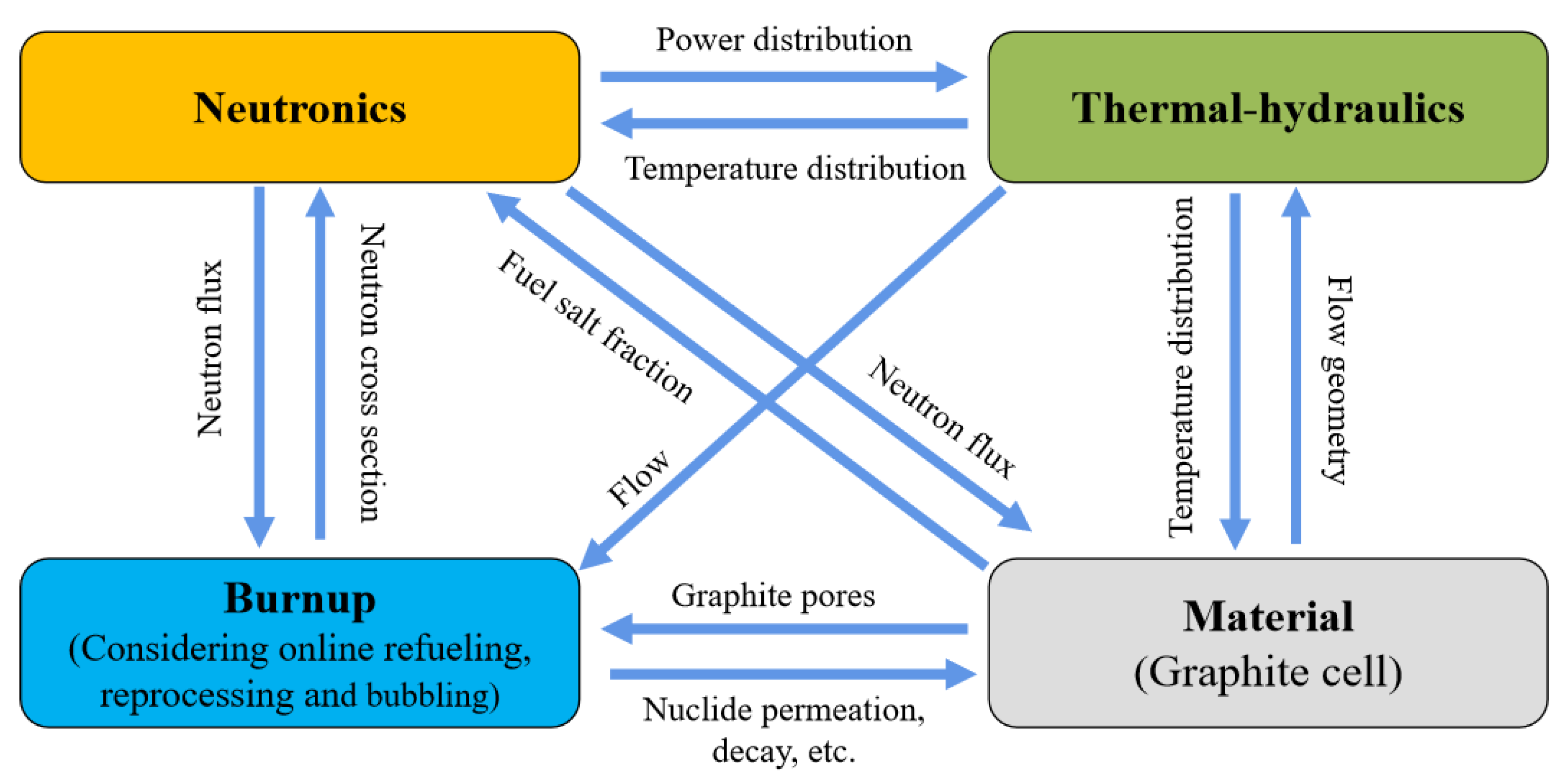
3.3. N-TH-BN-G Coupling Development

Graphite deformation is another important mechanism that closely couples with neutronics, thermal hydraulics, and burnup in a thermal MSR. Table 3 gives an overview of the development status of the N-TH-BN-G coupling models. In 1969, the volume deformation ν of graphite was evaluated using a parabolic curve, in terms of core temperature and neutron fluence by Scott and Eatherly [100]:
ν = A Φ t + B ( Φ t ) 2
where A and B are the core temperature-dependent constants. Under neutron flux (especially fast neutron with energy > 50 keV) irradiation, the graphite deformation ν firstly decreases to a minimal value νm and then increases with time. To avoid introducing a large amount of reactivity during core operation, it is necessary to exclude the fuel salt and xenon from the graphite. As for the first requirements, the pores of the graphite should be no larger than ~1 μ in diameter. Regarding the xenon permeating to the graphite, an allowable permeability is in the order of 10−8 cm2/s. Because we lack the definitive data, it is usually assumed that the pore size and permeability requirements can be maintained during neutron irradiation until the original graphite volume is reattained. At this point, the time τ is defined as the graphite lifespan, and can be calculated as:
0 = A Φ τ + B ( Φ τ ) 2 .
Then, the graphite distortion volume ν can be rewritten as:
v = 4 v m t τ ( 1 t τ ) .
The parameters   Φ τ and νm were estimated to be ( 9.36 8.39 × 10 3 T ) × 10 22 n/cm2 and ( 12.0 + 8.92 × 10 3 T ) % , respectively. The above equations were solved by coupling the core neutron flux and temperature distribution to evaluate the lifetime of graphite in the MSBR core. In this model, the mechanism of burnup is neglected, and the graphite temperature is simply calculated based on the heat transfer from the graphite to fuel salt, using an axial sine distribution of power. Meanwhile, a constant neutron flux (~5 × 10 14 n · cm−2 sec−1, with a neutron energy 50 keV) is taken by assuming the peak power density to be 63 W/cm3 [100].
In the study by Kasten et al. in 1969 [101], the mechanisms of graphite deformation were explored from the viewpoint of graphite stress under neutron flux irradiation at a given core temperature distribution. The corresponding stress-strain equations of graphite were given:
ϵ i = 1 E [ σ i μ ( σ j + σ k ) ] + 1 E [ σ i 1 2 ( σ j + σ k ) ] + 0 t k Φ [ σ i 1 2 ( σ j + σ k ) ] d t + 0 t g d t + α ( T T 0 )
where ϵ i is the total strain in the ith direction (I, j, k = r, θ, z), σ i indicates the stress in the ith direction, E is Young’s modulus, μ is Poisson’s ratio, k is the constant of secondary creep induced by irradiation, g is the time rate of radiation-induced dimensional changes, α is the differential dimensional change due to thermal expansion, and T 0 is the reference temperature. The right side of Equation (32) sums up the elastic strain, the saturated primary creep strain, the secondary creep strain, the imposed radiation-induced distortion, and the thermal strain. It was solved using an iterative process, where a zero-order approximation is first generated and then iterated by the subsequent first-order approximation, via updating the third term in the right side of Equation (32). The neutron flux and the temperature of the center channel in a thermal MSR were taken for the N-TH-G coupling calculation.
In 2020, Zhu et al. made an effort to couple the mechanisms of neutronics, thermal hydraulics, burnup, and graphite deformation to accurately evaluate the graphite lifespan in a small modular MSR. The neutronics calculation was carried out based on MCNP to provide a neutron flux. The nuclide evolution calculation, considering online refueling and reprocessing, was calculated using ORIGEN, and the thermal-hydraulic calculation was performed using a multi-channel model. The graphite dimensional change was then evaluated using a parabolic curve, as presented in Equation (29), based on the calculated neutron flux and temperature distribution. In turn, the dimensional change of graphite was fed back to the input of the geometry for the MCNP calculation but was not taken into account by the thermal hydraulics calculation. On the other hand, the temperature distribution of the core calculated by thermal hydraulics was also not fed back to the MCNP [102]. Later, in 2021, an attempt was made by Wang et al. to improve this model by employing Fluent (a CFD software) to provide more accurate temperature distribution. However, the improved model cannot perform burnup calculations and feed back the dimensional changes of graphite to the MCNP and CFD, mainly because of the technical challenges in coupling the calculation and a significantly high calculation cost [103].
In 2020, Stewart proposed an N-TH-G coupling model, termed GeN-foam-G, based on the multi-physics platform GeN-foam. The dimensional change of graphite under neutron flux irradiation was evaluated from the viewpoint of graphite mechanics. The model incorporates two graphite irradiated strain components. One of them accounts for the assessment of graphite dimensional change strain, while the other one is responsible for the creep strain analysis. These two irradiated strain components are performed, based on the neutron flux and temperature distribution provided by GeN-foam, in which the thermal-hydraulic calculation is implemented using the κ-ε turbulence porous media approach, while neutron calculation is conducted by adopting a neutronics subsolver with multigroup neutron diffusion. Feedback on the graphite dimensional changes to N-TH calculation, however, was not available, which is expected to be addressed in the future by the authors [29].
Table 3. Development status of the N-TH-BN-G coupling models.
Codes/Developers/PlatformsN ModelTH ModelBN ModelG Model
Scott and Eatherly, 1969 [100]Given neutron fluxLumped parameters -Parabolic curve
Kasten et al., 1969 [101]Given neutron flux Given temperature-Stress-strain
Zhu et al., 2020 [102]Monte CarloMulti-channel Time-stepParabolic curve
Wang et al., 2021 [103]Monte CarloCFD-Parabolic curve
Stewart, 2020 [28]3D neutron diffusionPorous media -Stress-strain

4. Improvements in the Future Work of the Multi-Physics Coupling Model Study

Calculation cost has become an important issue that greatly challenges the development of MSR multi-physics coupling models, as more mechanisms are coupled. In addition, orchestrating the solution processes of multiple, domain-specific codes running at different time scales is another issue that should be addressed in the future. Dedicated multi-physics platforms, such as MOOSE, can provide advanced computing techniques on parallel computing platforms and a coupled partial differential equations solution. Developing an MSR multi-physics coupling model on multi-physics platforms is an effective way to address the above two issues, attracting growing research attention. Another potential method is the machine-learning-based data-driven method, which can derive relationships or set of rules from data and solve more nonlinear complex problems [104]. It can act as a fast estimator or surrogate model for simulating some MSR mechanisms that have enough data available for training, such as neutronics and thermal hydraulics, to decrease the calculation cost. Up until now, many studies have been conducted on the application of machine learning in nuclear reactor neutronics, thermal hydraulics, and burnups calculation, which has formed a strong basis for the future improvement of MSR multi-physics coupling models [105].
The completeness of coupling is another issue that should be addressed for MSR multi-physics coupling model development. As introduced above, most of the MSR multi-physics coupling models only take into account part of the physical mechanisms or set a fixed value/distribution for certain physical mechanisms without feedback. Currently, there is a trend to integrate the mechanism of salt chemistry into the multi-physics coupling model, in view of the extraordinarily close connection between reactor physics and fuel salt chemistry in MSRs. In a technical report on ORNL in 2018, a framework coupling with the codes of Thermochimica (thermochemistry calculation), SCALE6 (nuclide evolution and power density calculation), and COBRA-TF (thermal-hydraulic calculation) was proposed [106]. Thermochimica is an open-source implementation of the CALPHAD method. It takes molar elemental combinations as the input and can calculate the lowest energy state, from which the equilibrium chemical combinations can be predicted. Some thermodynamic parameters, including heat capacity, enthalpy, the chemical potential of the system components, and the driving forces of metastable phases can be provided for thermal-hydraulic calculation. In turn, the thermal-hydraulic (COBRA-TF) calculation feeds back the temperature and pressure distribution to the chemistry evaluation (Thermochimica). SCALE6 is used to prepare the data of isotropic evolution and power density for Thermochimical and COBRA-TR, respectively. In 2021, Poschmann et al. realized the coupling between Thermochimical and ORIGEN (one module of SCALE6 was used to perform the isotropic evolution calculation), based on which, the time behavior of radio-toxic gases’ quantities in a molten salt fuel loop was explored [107]. In the same year, under the Nuclear Energy Advanced Modeling and Simulation (NEAMS) program, several NEAMS codes that are under development adopted the Gibbs energy minimization (GEM) solver to accurately evaluate the phase and chemical equilibria of FPs and actinides in molten salt systems, and to simulate the leaching and deposition of FPs by coupling with thermal fluids and electron-transport mechanisms [108]. From the view of completeness and the accuracy of simulation, coupling the mechanisms of fuel salt chemistry with the MSR reactor multi-physics is one aspect that should be seriously considered in the future.

5. Conclusions

Molten salt reactors are one type of liquid-fueled reactor that is able to perform online refueling, reprocessing, and helium bubbling to remove sparingly soluble FPs. The fuel utilization, safety, and economics can be significantly enhanced in an MSR, but the unique features of MSR would introduce a series of new physical mechanisms and phenomena, which causes great challenges in terms of numerical simulation. Compared with solid-fueled reactors, coupling between neutronics and thermal hydraulics is tighter since molten salt acts as both the fuel and the coolant. A delayed neutron precursor would flow out from the core, together with the flowing fuel salt, which decreases the fraction of delayed neutrons in the core and, in turn, influences the core safety. Online refueling, reprocessing, and helium bubbling can be regarded as the external physical mechanisms that change the evolution of nuclides in real-time, leading to a failure in the application of the conventional burnup calculation tools to MSR. The dimensional change of the graphite in the core under neutron irradiation is another important physical mechanism that influences the behavior of neutronics and thermal hydraulics. The above physical mechanisms and phenomena derived from the flowing of liquid fuel, graphite, and online refueling, reprocessing and helium bubbling couple with each other, necessitating the development of an MSR multi-physics coupling model.
In this study, the development status of the MSR N-TH, N-TH-BN, and N-TH-BN-G coupling models are extensively reviewed, to outline the problems and challenges that exist. The MSR N-TH coupling model is considered to be the key model of multi-physics coupling. Its development can be dated back to the 1960s, in which the first molten salt reactor, MSRE, was proposed and built by ORNL. Over around 60 years of development, the N-TH coupling model has been improved from the 0D model that couples point neutron kinetics with the lumped thermal hydraulics at the beginning of the 3D model. There is a trend that realizes N-TH coupling on multi-physics platforms, to take advantage of advanced computing techniques. The MSR N-TH-BN coupling model adds a dimension of burnup that must take into account the many unique mechanisms of MSR, including online refueling, reprocessing, and helium bubbling. Up until now, the calculation of burnup coupling with neutronics has been extensively studied, while thermal hydraulics is rarely coupled, which will necessitate more effort in any future N-TH-BN coupling study. The N-TH-BN-G coupling model additionally considers the mechanism of graphite dimensional change under neutron irradiation. Some efforts have been made for this coupling model, but it is still at the initial development stage, with some mechanisms being unilaterally coupled without feedback.
In the future, new methods and mechanisms can be considered to address the issues of calculation cost, the orchestration of the codes with the solution processes in different time scales, and the completeness of the multi-physics coupling model. Dedicated multi-physics platforms, such as MOOSE and VERA, can provide advanced computing techniques in parallel computing and the solution of coupled partial differential equations. They have recently been attracting growing attention and can be viewed as an effective way to decrease the calculation cost and orchestrate the codes with solution processes on a different time scale. Machine learning is another method that is expected to be used to accelerate the calculation of the MSR multi-physics model as it can solve nonlinear complex problems with a low calculation cost via establishing a fast estimator or surrogate model. Regarding the completeness of the MSR multi-physics coupling model, besides all the potential reactor’s physical mechanisms, molten salt chemistry is another mechanism that should be coupled since MSR is actually a chemical nuclear reactor, in which the reactor, physics and fuel salt chemistry have an extraordinarily close connection.

Author Contributions

Writing—original draft preparation, J.W.; supervision, J.C.; project administration, X.C.; investigation, C.Z.; resources, C.Y.; literature collection, Y.C. and A.Z.; data collection, H.Z. All authors have read and agreed to the published version of the manuscript.

Funding

This research was funded by the National Natural Science Foundation of China, grant number 12175300, the National Natural Science Foundation of China, grant number 11905285, Natural Science Foundation of Shanghai, grant number 20ZR1468700, the Chinese TMSR Strategic Pioneer Science and Technology Project, grant number XDA02010000.

Data Availability Statement

Not applicable.

Conflicts of Interest

The authors declare no conflict of interest.

References

  1. Wu, J.; Chen, J.; Zou, C.; Yu, C.; Cai, X.; Zhang, Y. Transition to thorium fuel cycle on a heavy water moderated molten salt reactor by using low enrichment uranium. Ann. Nucl. Energy 2022, 165, 108638. [Google Scholar] [CrossRef]
  2. Lung, M.; Gremm, O. Perspectives of the thorium fuel cycle. Nucl. Eng. Des. 1998, 180, 133–146. [Google Scholar] [CrossRef]
  3. GIF. Technology Roadmap for Generation IV Nuclear Energy Systems; GIF Technical Report No. GIF-002-00; GIF: 2002. Available online: https://www.gen-4.org/gif/upload/docs/application/pdf/2013-09/genivroadmap2002.pdf (accessed on 31 August 2022).
  4. Haubenreich, P.N.; Engel, J.R.; Prince, B.E.; Claiborne, H.C. MSRE Design and operations Report; Part III. Nuclear Analysis; Technical Report No. ORNL-TM-730; Oak Ridge National Lab.: Oak Ridge, TN, USA, 1964. [Google Scholar]
  5. Dolan, T.J. Molten Salt Reactors and Thorium Energy; Woodhead Publishing: Cambridge, UK, 2017. [Google Scholar]
  6. Serp, J.; Allibert, M.; Beneš, O.; Delpech, S.; Feynberg, O.; Ghetta, V.; Heuer, D.; Holcomb, D.; Ignatiev, V.; Kloosterman, J.; et al. The molten salt reactor (MSR) in generation IV: Overview and perspectives. Prog. Nucl. Energy 2014, 77, 308–319. [Google Scholar] [CrossRef]
  7. Nuttin, A.; Heuer, D.; Billebaud, A.; Brissot, R.; Le Brun, C.; Liatard, E.; Loiseaux, J.-M.; Mathieu, L.; Meplan, O.; Merle-Lucotte, E.; et al. Potential of thorium molten salt reactors: Detailed calculations and concept evolution with a view to large scale energy production. Prog. Nucl. Energy 2005, 46, 77–99. [Google Scholar] [CrossRef] [Green Version]
  8. Furukawa, K.; Lecocq, A.; Kato, Y.; Mitachi, K. Thorium molten-salt nuclear energy synergetics. J. Nucl. Sci. Technol. 1990, 27, 1157–1178. [Google Scholar] [CrossRef]
  9. Jorgensen, L. ThorCon reactor. In Molten Salt Reactors and Thorium Energy; Woodhead Publishing: Cambridge, UK, 2017; pp. 557–564. [Google Scholar]
  10. Leblanc, D. The integral molten salt reactor (IMSR). Can. Nucl. Soc. Bull. 2014, 35, 28–34. [Google Scholar]
  11. Wu, J.; Chen, J.; Kang, X.; Li, X.; Yu, C.; Zou, C.; Cai, X. A novel concept for a molten salt reactor moderated by heavy water. Ann. Nucl. Energy 2019, 132, 391–403. [Google Scholar] [CrossRef]
  12. Mathieu, L.; Heuer, D.; Brissot, R.; Garzenne, C.; Le Brun, C.; Lecarpentier, D.; Liatard, E.; Loiseaux, J.-M.; Méplan, O.; Merle-Lucotte, E.; et al. The thorium molten salt reactor: Moving on from the MSBR. Prog. Nucl. Energy 2006, 48, 664–679. [Google Scholar] [CrossRef] [Green Version]
  13. Wu, J.; Guo, C.; Cai, X.; Yu, C.; Zou, C.; Han, J.; Chen, J. Flow effect on 135I and 135Xe evolution behavior in a molten salt reactor. Nucl. Eng. Des. 2017, 314, 318–325. [Google Scholar] [CrossRef]
  14. Wu, J.; Chen, J.; Yu, C.; Zou, C.; Ma, Y.; Li, X.; Cai, X. 149Sm evolution behavior in a small modular molten salt reactor. Ann. Nucl. Energy 2018, 120, 100–107. [Google Scholar] [CrossRef]
  15. Dulla, S.; Ravetto, P. Interactions between fluid-dynamics and neutronic phenomena in the physics of molten-salt systems. Nucl. Sci. Eng. 2007, 155, 475–488. [Google Scholar] [CrossRef]
  16. Dulla, S.; Ravetto, P.; Rostagno, M. Neutron kinetics of fluid–fuel systems by the quasi-static method. Ann. Nucl. Energy 2004, 31, 1709–1733. [Google Scholar] [CrossRef]
  17. Nestor, C. Murgatroyd—An IBM 7090 Program for the Analysis of the Kinetics of the MSRE; Technical Report No. ORNL-TM-203; Oak Ridge National Lab.: Oak Ridge, TN, USA, 1962. [Google Scholar]
  18. Mitachi, K.; Yamana, Y.; Suzuki, T.; Furukawa, K.; Kato, Y. Neutronic Examination on Plutonium Transmutation by a Small Molten Salt Fission Power Station. Technical Report No. IAEA-TECDOC-840. In Proceedings of the a Technical Committee Meeting, Obninsk, Russia, 7–11 November 1994; International Atomic Energy Agency: Vienna, Austria, 1995; pp. 183–193. [Google Scholar]
  19. Mattioda, F.; Ravetto, P.; Ritter, G. Effective Delayed Neutron Fraction for Fluid-Fuel Systems. Ann. Nucl. Energy 2000, 27, 1523–1532. [Google Scholar] [CrossRef]
  20. Lapenta, G.; Mattioda, F.; Ravetto, P. Point kinetic model for fluid fuel systems. Ann. Nucl. Energy 2001, 28, 1759–1772. [Google Scholar] [CrossRef]
  21. Aufiero, M.; Cammi, A.; Geoffroy, O.; Losa, M.; Luzzi, L.; Ricotti, M.E.; Rouch, H. Development of an OpenFOAM model for the Molten Salt Fast Reactor transient analysis. Chem. Eng. Sci. 2014, 111, 390–401. [Google Scholar] [CrossRef]
  22. Fiorina, C.; Clifford, I.; Aufiero, M.; Mikityuk, K. GeN-Foam: A novel OpenFOAM® based multi-physics solver for 2D/3D transient analysis of nuclear reactors. Nucl. Eng. Des. 2015, 294, 24–37. [Google Scholar] [CrossRef]
  23. Linden, E. Coupled Neutronics and Computational Fluid Dynamics for the Molten Salt Fast Reactor. Master’s Thesis, Delft University of Technology, Delft, The Netherlands, 2012. [Google Scholar]
  24. Tiberga, M. Development of a High-Fidelity Multi-Physics Simulation Tool for Liquid-Fuel Fast Nuclear Reactors. Ph.D. Thesis, Delft University of Technology, Delft, The Netherlands, 2020. [Google Scholar]
  25. Ridley, G.; Huff, K.; Turk, M.; Lindsay, A. Multiphysics Analysis of Molten Salt Reactor Transients; Technical Report No. UIUC-ARFC-2017-01; University of Illinois at Urbana-Champaign: Champaign, IL, USA, 2017. [Google Scholar]
  26. Caruggi, F.; Cammi, A.; Cervi, E.; Di Ronco, A.; Lorenzi, S. Multiphysics modelling of gaseous fission products in the Molten Salt Fast Reactor. Nucl. Eng. Des. 2022, 392, 111762. [Google Scholar] [CrossRef]
  27. Di Ronco, A.; Lorenzi, S.; Giacobbo, F.; Cammi, A. An Eulerian Single-Phase Transport Model for Solid Fission Products in the Molten Salt Fast Reactor: Development of an Analytical Solution for Verification Purposes. Front. Energy Res. 2021, 9, 692627. [Google Scholar] [CrossRef]
  28. Pathirana, V.; Chvala, O.; Skutnik, S. Depletion dependency of molten salt reactor dynamics. Ann. Nucl. Energy 2022, 168, 108852. [Google Scholar] [CrossRef]
  29. Stewart, J. Gen-Foam Multiphysics Model Development for Molten Salt Reactors. Ph.D. Thesis, University of Nevada, Las Vegas, NV, USA, 2020. [Google Scholar]
  30. Bettis, E.S.; Schroeder, R.W.; Cristy, G.A.; Savage, H.W.; Affel, R.G.; Hemphill, L.F. The aircraft reactor experiment-design and construction. Nucl. Sci. Eng. 1957, 2, 804–825. [Google Scholar] [CrossRef] [Green Version]
  31. Nagy, K. Dynamics and Fuel Cycle Analysis of a Moderated Molten Salt Reactor. Ph.D. Thesis, Delft University of Technology, Delft, The Netherlands, 2012. [Google Scholar]
  32. Robertson, R.C.; Briggs, R.B.; Smith, O.L.; Bettis, E.S. Two-Fluid Molten-Salt Breeder Reactor Design Study; Technical Report No. ORNL-4528; Oak Ridge National Lab.: Oak Ridge, TN, USA, 1970. [Google Scholar]
  33. Kasten, P.R.; Bettis, E.S.; Robertson, R.C. Desing Studies of 1000-MW(e) MoltenSalt Breeder Reactors; Technical Report No. ORNL-3996; Oak Ridge National Lab.: Oak Ridge, TN, USA, 1966. [Google Scholar]
  34. Bettis, E.S.; Robertson, R.C. The design and performance features of a single-fluid molten-salt breeder reactor. Nucl. Appl. Tech. 1970, 8, 190–207. [Google Scholar] [CrossRef]
  35. Engel, J.R.; Grimes, W.W.; Bauman, H.F.; Mccoy, H.E.; Rhoades, W.A. Conceptual Design Characteristics of Denatured Molten-Salt Reactor with Once-Through Fueling; Technical Report No. ORNL/TM-7207; Oak Ridge National Lab.: Oak Ridge, TN, USA, 1980. [Google Scholar]
  36. Smith, J.; Simmons, W.E. An Assessment of a 2500 MWe Molten Chloride Salt Fast Reactor; Technical Report; United Kingdom Atomic Energy Authority Reactor Group: Oxfordshire, UK, 1974. [Google Scholar]
  37. World Nuclear Association. Available online: https://world-nuclear.org/information-library/current-and-future-generation/molten-salt-reactors.aspx (accessed on 31 August 2022).
  38. Mallapaty, S. China prepares to test thorium-fuelled nuclear reactor. Nature 2021, 597, 311–312. [Google Scholar] [CrossRef] [PubMed]
  39. Ignatiev, V.; Merzlyakov, A.; Afonichkin, V.; Khokhlov, V.; Salyulev, A. Transport properties of molten-salt reactor fuel mixtures: The case of Na, Li, Be/F and Li, Be, Th/F salts. In Proceedings of the Seventh Information Exchange Meeting on Actinide and Fission Product Partitioning and Transmutation, Jeju, Korea, 14–16 October 2002. [Google Scholar]
  40. Merle-Lucotte, E.; Heuer, D.; Le Brun, C.; Mathieu, L.; Brissot, R.; Liatard, E.; Meplan, O.; Nuttin, A. Fast thorium molten salt reactors started with plutonium. In Proceedings of the ICAPP’06 International Congress on Advances in Nuclear Power Plants, Reno, NV, USA, 4–8 June 2006. [Google Scholar]
  41. Zhang, D.; Liu, L.; Liu, M.; Xu, R.; Gong, C.; Zhang, J.; Wang, C.; Qiu, S.; Su, G. Review of conceptual design and fundamental research of molten salt reactors in China. Int. J. Energy Res. 2018, 42, 1834–1848. [Google Scholar] [CrossRef]
  42. Scott, I.; Abram, T.; Negri, O. Stable salt reactor design concept. In Proceedings of the International Thorium Energy Conference Gateway to Thorium Energy, Mumbai, India, 12–15 October 2015. [Google Scholar]
  43. Huke, A.; Ruprecht, G.; Weißbach, D.; Gottlieb, S.; Hussein, A.; Czerski, K. The Dual Fluid Reactor–A novel concept for a fast nuclear reactor of high efficiency. Ann. Nucl. Energy 2015, 80, 225–235. [Google Scholar] [CrossRef]
  44. Leblanc, D.; Rodenburg, C. Integral molten salt reactor. In Molten Salt Reactors and Thorium Energy; Woodhead Publishing: Cambridge, UK, 2017; pp. 541–556. [Google Scholar]
  45. Maiorino, J.R.; D’Auria, F.; Reza, A.J. An overview of thorium utilization in nuclear reactors and fuel cycle. In Proceedings of the 12th International Conference of the Croatian Nuclear Society, Zadar, Croatia, 3–6 June 2018. [Google Scholar]
  46. Lee, A.J. Neutronics and Thermal-Hydraulics Analysis of Transatomic Power Molten Salt Reactor (TAP MSR) Core under Load Following Operations. Master’s Thesis, University of Illinois at Urbana, Champaign, IL, USA, 2020. [Google Scholar]
  47. Wheeler, A.M.; Singh, V.; Miller, L.F.; Chvála, O. Initial calculations for source term of Molten Salt Reactors. Prog. Nucl. Energy 2021, 132, 103616. [Google Scholar] [CrossRef]
  48. Scarlat, R.O.; Laufer, M.R.; Blandford, E.D.; Zweibaum, N.; Krumwiede, D.L.; Cisneros, A.T.; Andreades, C.; Forsberg, C.W.; Greenspan, E.; Hu, L. Design and licensing strategies for the fluoride-salt-cooled, high-temperature reactor (FHR) technology. Prog. Nucl. Energy 2014, 77, 406–420. [Google Scholar] [CrossRef] [Green Version]
  49. Pedersen, T.J. Copenhagen Atomics waste burner. In Molten Salt Reactors and Thorium Energy; Woodhead Publishing: Cambridge, UK, 2017; pp. 599–607. [Google Scholar]
  50. Robertson, R.C. Conceptual Design Study of a Single-Fluid Molten Salt Breeder Reactor; Technical Report No. ORNL-4541; Oak Ridge National Lab.: Oak Ridge, TN, USA, 1971. [Google Scholar]
  51. Wu, J.; Yu, C.; Zou, C.; Jia, G.; Cai, X.; Chen, J. Influences of reprocessing separation efficiency on the fuel cycle performances for a Heavy Water moderated Molten Salt Reactor. Nucl. Eng. Des. 2021, 380, 111311. [Google Scholar] [CrossRef]
  52. Henson, R.; Perks, A.; Simmons, J. Lattice parameter and dimensional changes in graphite irradiated between 300 and 1350 °C. Carbon 1968, 6, 789–806. [Google Scholar] [CrossRef]
  53. Sides, W.H. MSBR Control Studies: Analog Simulation Program; Technical Report No. ORNL-TM-3102; Oak Ridge National Lab.: Oak Ridge, TN, USA, 1971. [Google Scholar]
  54. Auwerda, G.J. Computational Modeling of a Molten Salt Reactor. Master’s Thesis, Delft University of Technology, Delft, The Netherlands, 2007. [Google Scholar]
  55. Suzuki, N.; Shimazu, Y. Reactivity-initiated-accident analysis without scram of a molten salt reactor. J. Nucl. Sci. Technol. 2008, 45, 575–581. [Google Scholar] [CrossRef]
  56. Guo, Z.; Zhang, D.; Xiao, Y.; Tian, W.; Su, G.; Qiu, S. Simulations of unprotected loss of heat sink and combination of events accidents for a molten salt reactor. Ann. Nucl. Energy 2013, 53, 309–319. [Google Scholar] [CrossRef]
  57. Cai, J.; Xia, X. Analysis on reactivity initiated transient from control rod failure events of a molten salt reactor. Nucl. Sci. Technol. 2014, 25, 030602. [Google Scholar]
  58. Shi, C.; Cheng, M.; Liu, G. Development and application of a system analysis code for liquid fueled molten salt reactors based on RELAP5 code. Nucl. Eng. Des. 2016, 305, 378–388. [Google Scholar] [CrossRef]
  59. Lecarpentier, D.; Carpentier, V. A neutronic program for critical and nonequilibrium study of mobile fuel reactors: The Cinsf1D code. Nucl. Sci. Eng. 2003, 143, 33–46. [Google Scholar] [CrossRef]
  60. Krepel, J.; Grundmann, U.; Rohde, U.; Weiss, F.P. DYN1D-MSR dynamics code for molten salt reactors. Ann. Nucl. Energy 2005, 32, 1799–1824. [Google Scholar] [CrossRef]
  61. Zhang, D.; Qiu, S.; Su, G.; Liu, C.; Qian, L. Analysis on the neutron kinetics for a molten salt reactor. Prog. Nucl. Energy 2009, 51, 624–636. [Google Scholar] [CrossRef]
  62. Wang, S.; Rineiski, A.; Maschek, W. Molten salt related extensions of the SIMMER-III code and its application for a burner reactor. Nucl. Eng. Des. 2006, 236, 1580–1588. [Google Scholar] [CrossRef]
  63. Nicolino, C.; Lapenta, G.; Dulla, S.; Ravetto, P. Coupled dynamics in the physics of molten salt reactors. Ann. Nucl. Energy 2008, 35, 314–322. [Google Scholar] [CrossRef]
  64. Cammi, A.; Marcello, V.; Luzzi, L.; Vito, M.; Ricotti, M. A multi-physics modelling approach to the dynamics of molten salt reactors. Ann. Nucl. Energy 2011, 38, 1356–1372. [Google Scholar] [CrossRef]
  65. Yamamoto, T.; Mitachi, K.; Ikeuchi, K.; Suzuki, T. Transient characteristics of small molten salt reactor during blockage accident. Heat Transf. 2006, 35, 434–450. [Google Scholar] [CrossRef]
  66. Krepel, J.; Rohde, U.; Grundmann, U.; Weiss, F. DYN3D-MSR spatial dynamics code for molten salt reactors. Ann. Nucl. Energy 2007, 34, 449–462. [Google Scholar] [CrossRef]
  67. Zhuang, K.; Cao, L.; Zheng, Y.; Wu, H. Studies on the molten salt reactor: Code development and neutronics analysis of MSRE-type design. J. Nucl. Sci. Technol. 2015, 52, 251–263. [Google Scholar] [CrossRef] [Green Version]
  68. Cui, Y.; Chen, J.; Wu, J.; Zou, C.; Cui, L.; He, F.; Cai, X. Development and verification of a three-dimensional spatial dynamics code for molten salt reactors. Ann. Nucl. Energy 2022, 171, 109040. [Google Scholar] [CrossRef]
  69. Kophazi, J.; Lathouwers, D.; Kloosterman, J. Development of a three dimensional time-dependent calculation scheme for molten salt reactors and validation of the measurement data of the molten salt reactor experiment. Nucl. Sci. Eng. 2009, 163, 118–131. [Google Scholar] [CrossRef]
  70. Nagy, K.; Lathouwers, D.; T’Joen, C.; Kloosterman, J.; van der Hagen, T. Steady-state and dynamic behavior of a moderated molten salt reactor. Ann. Nucl. Energy 2014, 64, 365–379. [Google Scholar] [CrossRef]
  71. Bajpai, P.; Lorenzi, S.; Cammi, A. A multiphysics model for analysis of inert gas bubbles in Molten Salt Fast Reactor. Eur. Phys. J. Plus 2020, 135, 409. [Google Scholar] [CrossRef]
  72. Yang, G.; Jaradat, M.; Yang, W.; Lee, C. Development of coupled PROTEUS-NODAL and SAM code system for multiphysics analysis of molten salt reactors. Ann. Nucl. Energy 2022, 168, 108889. [Google Scholar] [CrossRef]
  73. Engel, J.R.; Haubenreich, P.N. Temperatures in the MSRE Core During Steady State Power Operations; Technical Report No. ORNL-TM-0378; Oak Ridge National Lab.: Oak Ridge, TN, USA, 1962. [Google Scholar]
  74. Zhang, D.L.; Qiu, S.Z.; Liu, C.L.; Su, G.H. Steady thermal hydraulic analysis for a molten salt reactor. Nucl. Sci. Technol. 2008, 19, 187–192. [Google Scholar] [CrossRef]
  75. Guo, Z.; Zhou, J.; Zhang, D.; Chaudri, K.; Tian, W.; Su, G.; Qiu, S. Coupled neutronics/thermal-hydraulics for analysis of molten salt reactor. Nucl. Eng. Des. 2013, 258, 144–156. [Google Scholar] [CrossRef]
  76. Laureau, A.; Rubiolo, P.R.; Heuer, D.; Merle-Lucotte, E.; Brovchenko, M. Coupled neutronics and thermal–hydraulics numerical simulations of a Molten Fast Salt Reactor (MFSR). In Proceedings of the Joint International Conference on Supercomputing in Nuclear Applications and Monte Carlo, Paris, France, 27–31 October 2013. [Google Scholar]
  77. Deng, B.; Cui, Y.; Chen, J.-G.; He, L.; Xia, S.-P.; Yu, C.-G.; Zhu, F.; Cai, X.-Z. Core and blanket thermal–hydraulic analysis of a molten salt fast reactor based on coupling of OpenMC and OpenFOAM. Nucl. Sci. Technol. 2020, 31, 85. [Google Scholar] [CrossRef]
  78. Wu, J.; Oka, Y. Core design of super LWR with double tube water rods. Nucl. Eng. Des. 2014, 269, 340–348. [Google Scholar] [CrossRef]
  79. Wu, J.; Maekawa, N.; Oka, Y. Single-pass core design of a low-temperature Super LWR. J. Nucl. Sci. Technol. 2013, 50, 1129–1138. [Google Scholar] [CrossRef] [Green Version]
  80. Wu, J.; Oka, Y. Improved single pass core design for high temperature Super LWR. Nucl. Eng. Des. 2013, 267, 100–108. [Google Scholar] [CrossRef]
  81. Bauman, H.F.; Cunningham, G.W., III; Lucius, J.L.; Kerr, H.T.; Craven, C.W., Jr. ROD: A Nuclear and Fuel-Cycle Analysis Code for Circulating-Fuel Reactors; Technical Report No. ORNL-TM-3359; Oak Ridge National Lab.: Oak Ridge, TN, USA, 1971. [Google Scholar]
  82. Becker, B.; Fratoni, M.; Greenspan, E. Feasibility of a critical molten salt reactor for waste transmutation. Prog. Nucl. Energy 2008, 50, 236–241. [Google Scholar] [CrossRef]
  83. Merlelucotte, E.; Doligez, X.; Heuer, D.; Allibert, M.; Ghetta, V. Simulation tools and new developments of the molten salt fast reactor. Rev. Générale Nucléaire 2010, 6, 95–100. [Google Scholar]
  84. Doligez, X.; Heuer, D.; Merle-Lucotte, E.; Allibert, M.; Ghetta, V. Coupled study of the Molten Salt Fast Reactor core physics and its associated reprocessing unit. Ann. Nucl. Energy 2014, 64, 430–440. [Google Scholar] [CrossRef]
  85. Sheu, R.J.; Chang, C.H.; Chao, C.C.; Liu, Y. Depletion analysis on long-term operation of the conceptual molten salt actinide recycler & transmuter (mosart) by using a special sequence based on scale6/triton. Ann. Nucl. Energy 2013, 53, 1–8. [Google Scholar]
  86. Zou, C.; Cai, X.; Jiang, D.; Yu, C.; Li, X.; Ma, Y.; Han, J.; Chen, J. Optimization of temperature coefficient and breeding ratio for a graphite-moderated molten salt reactor. Nucl. Eng. Des. 2015, 281, 114–120. [Google Scholar] [CrossRef]
  87. Aufiero, M.; Cammi, A.; Fiorina, C.; Leppänen, J.; Luzzi, L.; Ricotti, M. An extended version of the SERPENT-2 code to investigate fuel burn-up and core material evolution of the Molten Salt Fast Reactor. J. Nucl. Mater. 2013, 441, 473–486. [Google Scholar] [CrossRef]
  88. Fiorina, C.; Cammi, A.; Krepel, J.; Mikityuk, K.; Ricotti, M. Preliminary analysis of the MSFR fuel cycle using modified-EQL3D procedure. In Proceedings of the ICONE20, Anaheim, CA, USA, 30 July–3 August 2012. [Google Scholar]
  89. Frima, L. Burnup in a Molten Salt Fast Reactor. Master’s Thesis, Delft University of Technology, Delft, The Netherlands, 2013. [Google Scholar]
  90. Graham, A.; Collins, B.; Salko, J.; Taylor, Z.; Gentry, C. Development of Molten Salt Reactor Modeling and Simulation Capabilities in VERA. In Proceedings of the Global/Top Fuel Conference, Seattle, WA, USA, 22–27 September 2019. [Google Scholar]
  91. Di Ronco, A.; Lorenzi, S.; Giacobbo, F.; Cammi, A. Multiphysics analysis of RANS-based turbulent transport of solid fission products in the Molten Salt Fast Reactor. Nucl. Eng. Des. 2022, 391, 111739. [Google Scholar] [CrossRef]
  92. Engel, J. Preliminary Equations to Describe Iodine and Xenon Behavior in the MSRE; Technical Report No. ORNL-CF-62-11-69; Oak Ridge National Lab.: Oak Ridge, TN, USA, 1962. [Google Scholar]
  93. Watson, G.; Evans, R. Xenon Diffusion in Graphite: Effects of Xenon Absorption in Molten Salt Reactors Containing Graphite; Technical Report No. ORNL-TM-262; Oak Ridge National Lab.: Oak Ridge, TN, USA, 1962. [Google Scholar]
  94. Kedl, R.; Houtzeel, A. Development of a Model for Computing 135Xe Migration in the MSRE; Technical Report No. ORNL-4069; Oak Ridge National Laboratory: Oak Ridge, TN, USA, 1967. [Google Scholar]
  95. Engel, J.R.; Steffy, R.C. Xenon Behavior in the Molten Salt Reactor Experiment; Technical Report No. ORNL-TM-3464; Oak Ridge National Lab.: Oak Ridge, TN, USA, 1971. [Google Scholar]
  96. Price, T.; Chvala, O.; Bereznai, G. A dynamic model of xenon behavior in the Molten Salt Reactor Experiment. Ann. Nucl. Energy 2020, 144, 107535. [Google Scholar] [CrossRef]
  97. Wu, J.; Li, X.; Hu, J.; Chen, J.; Yu, C.; Zou, C.; Cai, X. Influence of Xe-135 Dynamic Behavior on Core Operation Safety for a Molten Salt Reactor. In Proceedings of the 2018 26th International Conference on Nuclear Engineering, London, UK, 22–26 July 2018. [Google Scholar]
  98. Taylor, Z.; Salko, R.; Graham, A.M.; Collins, B.S.; Maldonado, G.I. Implementation of two-phase gas transport into VERA for molten salt reactor analysis. Ann. Nucl. Energy 2022, 165, 108672. [Google Scholar] [CrossRef]
  99. Walker, S.A.; Ji, W. Species transport analysis of noble metal fission product transport, deposition, and extraction in the molten salt reactor experiment. Ann. Nucl. Energy 2021, 158, 108250. [Google Scholar] [CrossRef]
  100. Scott, D.; Eatherly, W.P. Graphite and xenon behavior and their influence on molten-salt reactor design. Nucl. Appl. Tech. 1970, 8, 179–189. [Google Scholar] [CrossRef]
  101. Kasten, P.R.; Bettis, E.S.; Cook, W.H.; Eatherly, W.P.; Holmes, D.K.; Kedl, R.J.; Kennedy, C.R.; Kirslis, S.S.; McCoy, H.E.; Perry, A.M. Graphite behavior and its effects on MSBR performance. Nucl. Eng. Des. 1969, 9, 157–195. [Google Scholar] [CrossRef]
  102. Zhu, G.; Guo, W.; Kang, X.; Zou, C.; Zou, Y.; Yan, R.; Dai, Y. Neutronic effect of graphite dimensional change in a small modular molten salt reactor. Int. J. Energy Res. 2021, 45, 11976–11991. [Google Scholar] [CrossRef]
  103. Wang, Y.; Guo, W.; Zhu, G.; Dai, Y.; Zhong, Y.; Zou, Y.; Chen, J.; Cai, X. A new structure design to extend graphite assembly lifespan in small modular molten salt reactors. Int. J. Energy Res. 2021, 45, 12247–12257. [Google Scholar] [CrossRef]
  104. Avramova, M.; Abarca, A.; Hou, J.; Ivanov, K. Innovations in Multi-Physics Methods Development, Validation, and Uncertainty Quantification. J. Nucl. Eng. 2021, 2, 44–56. [Google Scholar] [CrossRef]
  105. Gomez-Fernandez, M.; Higley, K.; Tokuhiro, A.; Welter, K.; Wong, W.; Yang, H. Status of research and development of learning-based approaches in nuclear science and engineering: A review. Nucl. Eng. Des. 2020, 359, 110479. [Google Scholar] [CrossRef]
  106. Mcmurray, J.W.; Besmann, T.M.; Ard, J.; FItzpatrick, B.; Piro, M.; Jerden, J.; Williamson, M.; Collins, B.S.; Betzler, B.R.; Qualls, A.L. Multi-Physics Simulations for Molten Salt Reactor Evaluation: Chemistry Modeling and Database Development; Technical Report No. ORNL/SPR-2018/864; Oak Ridge National Lab: Oak Ridge, TN, USA, 2018. [Google Scholar]
  107. Poschmann, M.; Bajpai, P.; Fitzpatrick, B.W.; Piro, M.H. Recent developments for molten salt systems in Thermochimica. Calphad 2021, 75, 102341. [Google Scholar] [CrossRef]
  108. Feng, B.; Shahbazi, S.; Fang, J.; Fei, T.; Shaver, D. Application of NEAMS Codes to Capture MSR Phenomena; Technical Report No. ANL/NSE-21/48; Argonne National Lab.: Lemont, IL, USA, 2021. [Google Scholar]
Figure 1. The research and development (R&D) activities of MSRs worldwide.
Energies 15 08296 g001
Figure 2. Overview of a molten salt reactor system.
Energies 15 08296 g002
Figure 3. Multi-physics mechanisms in MSRs.
Energies 15 08296 g003
Figure 4. Multi-physics couplings among MSR mechanisms.
Energies 15 08296 g004
Figure 5. Point neutronic kinetics and the thermal-hydraulic coupling scheme.
Energies 15 08296 g005
Figure 6. Lumped-parameter model for the thermal-hydraulic calculation of MSBR.
Energies 15 08296 g006
Figure 7. Modeling of 135Xe behavior in the primary loop.
Energies 15 08296 g007
Table 1. Summary of the current N-TH coupling models.
Dim.Codes/Developers/Platforms, YearNeutronics ModelThermal Hydraulics ModelCoupling TechniquesApplication
0DMURGATROYD, 1962 [17]; Sides, 1971 [53]; Lapenta et al., 2001 [20]; Dulla et al., 2004 [16]Point kinetics Lumped parameters External Thermal/fast MSRs
Auwerda, 2007 [54]; Suzuki et al., 2008 [55]; Guo et al., 2013 [56]; Cai et al., 2014 [57]Point kineticsSingle-channelExternalThermal MSRs
Improved RELAP5, 2016 [58]Point kineticsMulti-channelExternalThermal MSRs
1DCinsf1D, 2003 [59]; DYN1D-MSR, 2005 [60]1D neutron diffusionSingle-channelExternalThermal MSRs
2DZhang et al., 2009 [61]2D cylindrical neutron diffusionModeling heat transfer between the fuel salt and boundary graphiteExternalFast MSRs
Improved SIMMER-III, 2006 [62]; Nicolino et al., 2008 [63]2D cylindrical neutron diffusion2D CFDInternalFast MSRs
Cammi et al., 2011 [64]2D cylindrical neutron diffusion2D CFDExternalFast MSRs
Yamamoto et al., 2006 [65]2D cylindrical neutron diffusionPorous mediumExternalThermal MSRs
3DDYN3D-MSR, 2007 [66]; MOREL, 2015 [67]; TMSR-3D, 2022 [68]3D neutron diffusionMulti-channelExternalThermal MSRs
DALTON and THERM, 2009 [69]3D neutron diffusionMulti-channel and 3D heat transfer in graphiteExternalFast MSRs
Nagy et al., 2014 [70]3D neutron diffusionPorous medialExternalFast MSRs
DALTON and HEAT, 2012 [23]; PHANTON-SN and DGFlows, 2020 [24]3D neutron diffusion3D-CFDExternalFast MSRs
OpenFOAM, 2014 [21]3D neutron diffusion3D-CFDInternalFast MSRs
COMSOL, 2020 [71]3D neutron diffusion3D two-phase flowInternalFast MSRs
Moltres under MOOSE framework, 2017 [25]3D neutron diffusion3D-CFDInternalThermal MSRs
PROTEUS-NODAL and SAM under MOOSE framework, 2022 [72]3D neutron transportMulti-channel for core and 1D for external components ExternalFast/Thermal MSRs
Publisher’s Note: MDPI stays neutral with regard to jurisdictional claims in published maps and institutional affiliations.

