Abstract
During the charging and discharging process of a lithium-ion power battery, the intercalation and deintercalation of lithium-ion can cause volume change in the jellyroll and internal stress change in batteries as well, which may lead to battery failures and safety issues. A mathematical model based on a plane strain hypothesis was established to predict stresses in both the radial and hoop directions, with the hoop stress of each winding layer of the jellyroll obtained. Displacements of the steel case, the jellyroll, and the core of the battery during the charging and discharging processes were also analyzed, with the effect of lithium-ion concentration and the battery size discussed. The research results can explain well the wrinkling and fracture of the jellyroll.
1. Introduction
With the rapid growth of electric vehicle holdings, an increasing number of battery-related accidents is reported. The reasons for the failure of batteries are many and complex [1]. In order to improve the safety of electric vehicles, lithium-ion power batteries, the main power source currently used, needs to be further studied.
The operating principle of the lithium-ion power battery is back and forth movement of lithium-ion between the cathode and the anode during the charging and discharging process. Diffusion-induced stresses in the battery are caused by volume changes during lithiation and delithiation in the active materials, leading to various failure modes [2], including wrinkling of the inner jellyroll and fracture of the outer jellyroll, as shown in Figure 1 [3,4,5]. Battery failures caused by diffusion-induced stress are an active research topic [6].
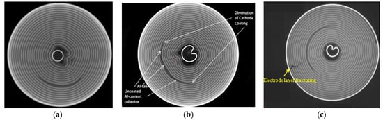
Figure 1.
The CT diagram of deformation of jellyroll: (a,b) wrinkling of inner jellyroll [3]. Reprinted with permission from Ref. [4]. 2018, Elsevier.; (c) fracture of outer jellyroll. Reprinted with permission from Ref. [5]. 2020, Elsevier.
In terms of experimental research, transmission electron microscope (TEM) and computed tomography (CT) are two powerful tools to investigate the battery inside. TEM usually was used to in situ observe the microstructure evolution and the electrochemical lithiation/delithiation behaviors of active material particles in the nanoscale [7,8], whereas CT was used to observe the interior of the battery in the microscale [3,4,5]. By then, the inner structure of the battery is exposed non-destructively.
A number of theoretical analyses have been seen in the effort to obtain the stress state inside the battery. Chen [9] looked at a partial molar volume of the electrode material to calculate diffusion-induced stresses caused by the volume change. Mei [10] applied a variation rule of the volume change rate of electrode material with the local state of charge (SOC). Zhang [11] used the lithiation expansion coefficient α of the electrode material to obtain diffusion-induced stresses. Christensen et al. [12] established a mathematical model that calculates volume changes and concentrations, and stress profiles of a spherical particle of the electrode material during intercalation and deintercalation of lithium-ion. Peng et al. [13,14] discussed the effects of the diffusion coefficient, Young’s modulus, and the partial molar volume on the stress field in a cylindrical electrode and established a mathematical model considering the expansion rate of the medium. These studies can provide the stress state of a single electrode or active material particles under different conditions well, but they cannot predict the stress state of the battery on a cell scale due to no case and steel core included in their mathematical models. As a result, these studies cannot explain the wrinkle and fracture of a battery cell.
This paper presents the stress analysis in the charging and discharging process of the whole cell of a cylindrical lithium-ion power battery. Firstly, the constitutive models of the battery cell under a plane strain state were established to analyze stresses in the radial and hoop directions, and displacements of the steel core, the jellyroll, and the case. Secondly, the effects of the cell size and lithium-ion concentration on the stresses and displacements were discussed. Finally, the hoop stress of every layer of the cathode, the separator, and the anode of jellyroll was obtained, providing a better understanding of the potential failures of lithium-ion power batteries.
2. Geometric Modeling
As shown in Figure 2, the cylindrical battery cell has three main components, i.e., the core, the jellyroll, and the case. The core and the case are typically made of steel shells with a certain wall thickness. The jellyroll is laminated and wound with four thin layers of components in the order of the separator, the anode, the separator again, and the cathode. Generally, the electrode is composed of metal substrates and active material particles. The anode consists of a copper current collector and active particles such as carbon, silicon, or others with adhesive composition, and the cathode is made of an aluminum current collector and active material particles, i.e., LMO, LFO, LCO, or others, with adhesive composition.
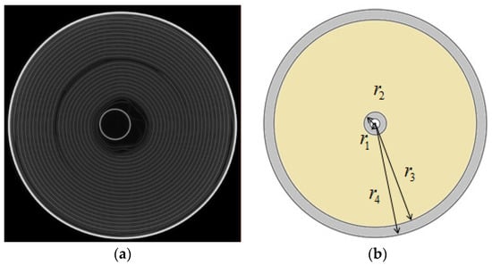
Figure 2.
(a) The CT image of cross-section of as-received battery; (b) the equivalent model of battery.
In our modeling, each layer of the jellyroll (including the anode and cathode) is assumed to be macroscopically isotropic. The basic components of the jellyroll (separator–anode–separator–cathode) are taken as a representative volume element. A cylindrical coordinate system is adopted, with the z-axis as the axial direction, the θ-axis as the hoop direction, and the r-axis as the radial direction.
3. Mechanical–Electrochemical Model
The loading capacity and the safety threshold of the whole battery structure can be determined by testing the mechanical properties of the battery at the macroscopic scale [15,16,17]. Meanwhile, the constitutive model of the battery needs to be established, as shown in the following sections, to study the deformation mechanism of the battery.
3.1. The Fundamental Equations of the Battery
Due to the strong constraint of the external case, the influence of the top and bottom ends of the battery cell can be ignored during the process of charging and discharging on the deformation of the jellyroll, and the analysis can thus be simplified as a plane strain (axisymmetric) problem. The radial displacement of the battery is denoted by u, and the radial and hoop stress by and , respectively. The subscripts I, J and O are used to denote the steel core, the jellyroll and the case, respectively. Only stresses and strains in the linear elastic stage are considered. Young’s modulus is denoted by , the Poisson’s ratio by , the molar volume by , and the lithium-ion concentration by . , , and are, respectively, the radius of the boundary of the steel core, the jellyroll block, and the case as shown in Figure 2.
3.1.1. The Fundamental Equations of the Steel Core and Case
For the steel core and the case, their constitutive equations, geometric equations, and equilibrium equations are identical, but with different dimensions.
The constitutive equations under the plane strain state are,
The stresses can be derived as,
Under the assumption of small deformation, the geometric equations are as follows:
Ignoring the body force, the equilibrium Equation [18] can be derived into Equation (4).
Combining the constitutive equations, the geometric equations and the equilibrium equation, the following closed form solutions can be deduced,
where and are undetermined coefficient.
3.1.2. The Fundamental Equations of the Jellyroll
The constitutive equations of the jellyroll under plane strain state are as follows,
The stresses are then expressed as,
The format of the geometric equations and equilibrium equations of the jellyroll are identical to those of the case and the steel core.
Combining the constitutive equations, geometric equations and equilibrium equation, the following equations can be deduced.
where , , , , and in the above Equations (5)–(7) and (10)–(12) are undetermined coefficient, and can be calculated with the introduction of the boundary conditions.
3.2. The Boundary Conditions
For the boundary conditions about , there are three possible cases.
- In the first case, the three components of the battery interact with each other. Then, the displacement and radial compressive stress on the steel core can be obtained, Therefore, the boundary conditions are as follows:
- In the second case, . In this case, the steel core is under tension in radial direction and the steel core expands radially. Physically, this situation can be regarded as nonexistence.
- The third case is . There is no interaction between the steel core and the jellyroll, namely the stress at the contact region is 0. Then, the boundary conditions are as follows:
3.3. Analysis of Hoop Stress, Radial Stress, and Displacement
In the first case, Equation (13) is taken into the radial displacement equations and radial stress equations of the steel core, jellyroll, and case of the battery. Then, relational expressions with unknown parameters of Ai and Bi, i = I, J, O, can be obtained in Equations (15)–(20).
where
In the third case, the boundary condition (14) is put into the radial displacement equations and the radial stress equations of the jellyroll and case. Then, Equations (21)–(24) are obtained as,
4. Stress Analysis and Calculation Cases
4.1. Computational Analysis of 18650 Battery
Taking 18,650 cylindrical lithium-ion power battery as an example, the battery dimension details are , , and . The materials of steel for the core and the case are identical, with the elastic modulus, yield strength, tensile strength, and Poisson’s ratio being , , , and . The steel core and the case are circular cylinders with a wall thickness of 0.2 mm. The jellyroll material data are shown in Table 1.

Table 1.
Material properties of components of jellyroll. Reprinted with permission from Ref. [19]. 2016, Elsevier [20,21].
The first boundary condition case can be obtained by using the data in Table 1, following Equation (13) in Section 3.3. The displacement, radial stress, and hoop stress of steel core, jellyroll, and case are obtained as follows:
It can be seen that displacements and stresses in the battery change linearly with the partial molar volume and the lithium-ion concentration during the charging and discharging process, but they are distributed nonlinearly over the radius.
During the process of charging, the anode expands due to lithiation, and the cathode contracts due to delithiation. Considering the effect of both anode and cathode on the deformation of the battery, the value of of the jellyroll needs the thickness of each component (separator(1)–anode(2)–separator(3)–cathode(4)) for the whole winding as shown in Figure 3. The set of the thickness of each component is as follows [19],
where the subscripts se, an, and ca refer to separator, anode, and cathode, respectively. Therefore, the anode and cathode volume ratio can be calculated as follows:
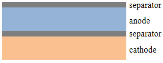
Figure 3.
The schematic diagram of representative volume element of jellyroll.
Note that for graphite and lithium manganate [22,23,24,25], the values of the parameters involved in the calculations are,
In order to obtain the value of of the jellyroll, the law of mixture of composite material should be considered. Consequently, the values of the parameters about expansion are obtained according to the formula as follows,
For the case of saturated concentration, the values of the displacement, the hoop stress, and the radial stress in a fully charged state are calculated and shown in Figure 4, Figure 5 and Figure 6, respectively.
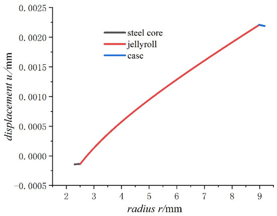
Figure 4.
Displacements of 18650 battery on a fully charged state.
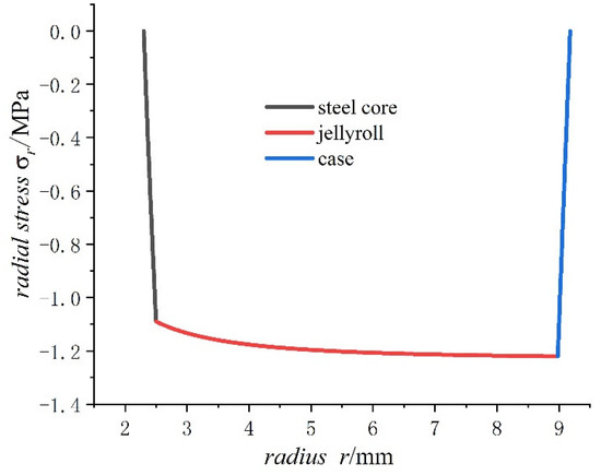
Figure 5.
Radial stresses of 18650 battery on a fully charged state.
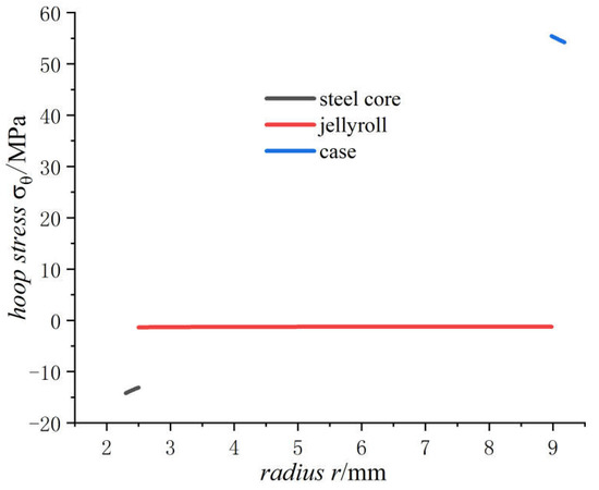
Figure 6.
Hoop stresses of 18650 battery on a fully charged state.
- The radial stress generated by charging is all compressive. As the radius increases from the inner radius to the outer radius, the radial compressive stress of the steel core and jellyroll increases gradually, while the radial compressive stress of the case decreases until it reaches zero.
- The hoop stress of the steel core and jellyroll under charging are all compressive, and its value decreases with the increase in the radius. Meanwhile the hoop stress of the case generated by charging is tensile, which decreases with the increase in radius. It should be noted that the stress distribution of the electrode in Figure 6 is not constant, and the magnitude decreases marginally.
- For the fully charged battery, the displacement of the steel core shows negative values for contraction inwards. The displacement of the case shows positive values for expansion outward. The displacement of the jellyroll is zero at The value near the steel core is negative and the value near the case is positive. Therefore, we can conclude that the jellyroll deforms both inward and outward and is constrained by the steel core and the case.
The above conclusions show that the jellyroll is subjected to compressive stresses. With excessive battery degradation, the deformation can reach to the extent until buckling occurs, and consequently wrinkle appears. These would have adverse effects on the health condition of the battery. The stress and displacement analyses developed can help to provide a detailed explanation for the damage phenomenon.
It is generally considered that the compressive hoop stress is the main reason for the failure of electrode materials [11,26,27,28,29,30]. The active material on the electrode has the smallest yield strength among battery component materials except the separator, so the failure of electrode materials is an important cause for battery aging and deterioration.
4.2. Stress Comparison of Batteries at Different Sizes after Charging
For lithium-ion power batteries of different models, only size and dimension details change in the stress analyses as shown in Table 2, with other data remaining the same. Figure 7, Figure 8 and Figure 9 show the displacement and stress curves of the core, the jellyroll, and the case in terms of the radius, respectively.
Table 2.
The geometric parameters of four types of batteries.
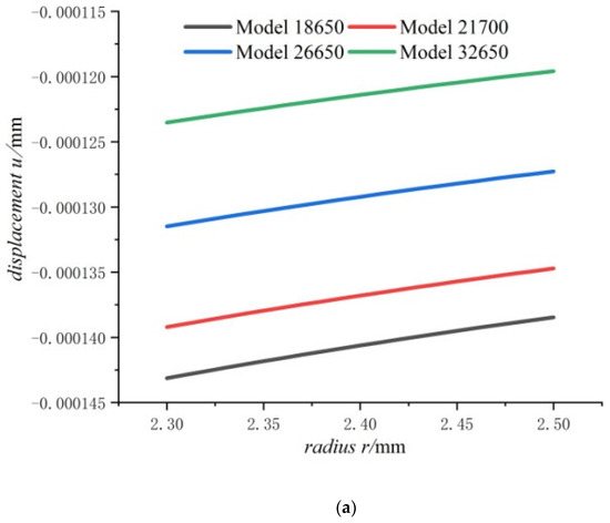
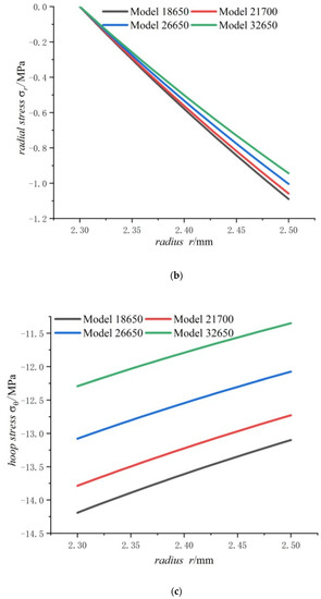
Figure 7.
Displacements and stresses of the steel core of four types of lithium-ion power batteries in a fully charged state: (a) displacements; (b) radial stresses; (c) hoop stresses.
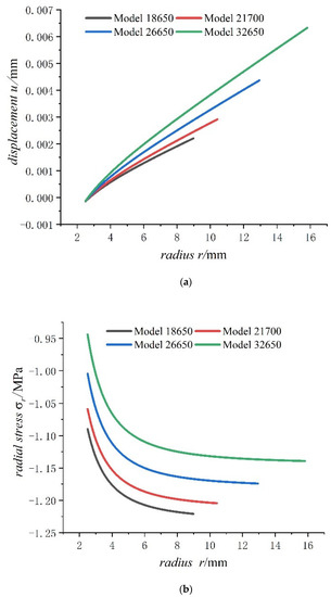
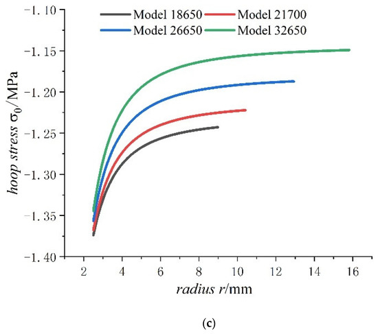
Figure 8.
Displacements and stresses of jellyroll of four types of lithium-ion power batteries on a fully charged state: (a) displacements; (b) radial stresses; (c) hoop stresses.
Figure 9.
Displacements and stresses of case of four types of lithium-ion power batteries on a fully charged state: (a) displacements; (b) radial stresses; (c) hoop stresses.
Figure 7 shows that the displacement, radial compressive stress, and hoop compressive stress at any point of the steel core decrease with the increase in the cell size. This means that the bigger the cell size, the smaller the displacement, the radial stress and the hoop stress of steel core. It also can be found that the displacement and the hoop stress of steel core are more sensitive to cell size than the radial stress. It also can be seen that for the steel core, the displacement is small, and stresses are far lower than strength of steel.
As can be seen from Figure 8, the radial displacement of jellyroll increases with the increase in cell size, and the displacement of jellyroll has both negative values and positive values, with negative values representing expanding inwards and positive values representing expanding outward. There is a position that the value of displacement is 0 in the jellyroll. Meanwhile as the external radius of the battery increases, the constant displacement of the jellyroll moves inwards, with the inward expansion displacement of jellyroll gradually decreasing and the outward expansion displacement of jellyroll gradually increasing. In addition, the jellyroll is subjected to radial compressive stress and hoop compressive stress anywhere, and the values of radial compressive stress decreases with the increase in battery size as well as hoop compressive stress. It also can be seen for batteries of all sizes that the hoop stresses of jellyroll decrease rapidly and then slowly, while radial stress increases rapidly and then slowly. The rapidly decreasing hoop stress means that the part of jellyroll close to the steel core is most prone to wrinkle. The hoop stress of the inner jellyroll next to steel core is not sensitive to size of the battery.
It can be seen from Figure 9 that the displacement of the case increases with the increase in the external radius of the battery. With the increase in external radius of battery, the radial compressive stress of the case decreases slowly while the hoop tensile stress increases. Due to small thickness of the case, the radial stresses, varying from certain value to zero, have very high stress gradient and keep almost same for batteries of all sizes. The displacement and hoop stress are more sensitive to cell size than radial stress like in Figure 7. The bigger the cell size, the more dangerous the case is. Although hoop stresses of case are growing fast, the rate of growth is slowing down with cell size, because the hoop stress is proportional to as shown in formula of in Section 4.1.
4.3. Effect of Lithium-Ion Concentration on Mechanical Properties of Battery
The intercalation [31,32] and deintercalation of lithium-ion can cause a volume change in the jellyroll. The lithium-ion battery expands and contracts under charging and discharging, respectively. The volume change is related to the movement of lithium-ion between the cathode and the anode in the process. The change varies with the amount of charging or the lithium-ion concentration. To understand the effect, lithium-ion saturation concentration in Model 18650 is taken at 0.5, 0.8, 1.5, 2 and 3 times of that of the jellyroll, with other parameters remaining unchanged. Among these values, 0.5 and 0.8 times can also be considered as corresponding to 50% and 80% of state of charge of the graphite anode and lithium manganate cathode, respectively. For ease of calculation, 1.5, 2 and 3 times can also be considered as corresponding to the values of the parameters involved in inflation of other anode materials. For example, silicon has highest theoretical specific capacity of 4200 mAh/g, which is about ten times that of the graphite anode materials. Different silicon content in anode could result in different saturation concentration.
Figure 10, Figure 11 and Figure 12 shows the trend of the displacement, the radial stress and the hoop stress in Model 18650 at different lithium-ion concentrations in terms of the radius. It can be seen that the larger the lithium-ion concentration, the larger the displacement as well as the radial and hoop stresses.
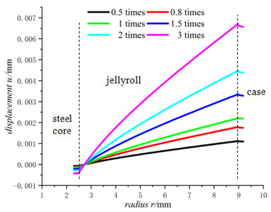
Figure 10.
Displacements of 18650 battery at different lithium-ion concentrations.
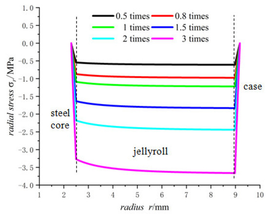
Figure 11.
Radial stresses of 18650 battery at different lithium-ion concentrations.
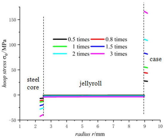
Figure 12.
Hoop stresses of 18650 battery at different lithium-ion concentrations.
There are constraints to the jellyroll by the steel core and the case, and the component materials of the jellyroll are different so the properties of these materials determine the maximum expansion degree that the battery can sustain. If the lithium-ion concentration of the battery is too high, the expansion may become large, resulting in crushed jellyroll near the steel core and the case, and even fracture of the case [33].
5. Layer Analyses of the Jellyroll
5.1. Calculation of the Hoop Stress of Each Jellyroll Component
For the purpose of obtaining stresses inside the jellyroll, the jellyroll is analyzed layer by layer by considering the four components of the jellyroll (separator(1)–anode(2)–separator(3)–cathode(4)) for the whole winding. The set of the thickness of each component is as follows [19],
where the subscripts se, an, and ca refer to separator, anode, and cathode, respectively.
It is assumed that the jellyroll has n layers of windings, each winding has a radial thickness of t and an axial length of h. As shown in Figure 2, the internal radius of the jellyroll is set as , and the external radius is set as ; hence, we have . Each winding is composed of a layer sequence of separator–anode–separator–cathode, and the radial thickness of the four layers is assumed to be , , , , respectively.
In the ith winding, the hoop forces of the four layers are , , , and , respectively. Denoting the whole hoop force of the ith winding as , we then have . Noting that the whole hoop force of the ith winding is equal to the sum of the hoop forces of the four layers (separator–anode–separator–cathode), we thus have,
where
It can be assumed that the four layers have the identical hoop strain, , where is the hoop strain of the winding, and , , , and are the hoop strains of the four individual layers in the winding, respectively.
By applying the parameters in Table 2 and the radial thickness of the four-layer winding, it can be obtained that . Based on Equation (25), we can obtain the following,
Hence,
Additionally,
After integration, it gives,
and
and are the hoop stress of the two separators in the ith winding, respectively. In addition, and are the hoop stress of the anode and the cathode in the same winding, respectively.
5.2. Hoop Stress Distribution in the Winding
With the hoop stress of each layer in the jellyroll winding, the distribution of the hoop stress in the jellyroll can be obtained as shown in Figure 13 for battery Model 18650.
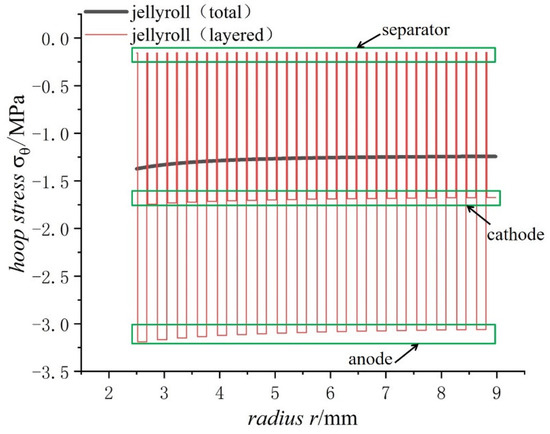
Figure 13.
Comparison of the total and layered hoop stresses in the jellyroll of 18650 battery on a fully charged state.
As can be seen from Figure 13, the hoop stress of each layer of the jellyroll changes in a stepped distribution due to the layered winding. The separator lies between the cathode and the anode, with the purpose of physical isolation between them to prevent the short circuit inside the battery. Since most lithium-ion power batteries are packaged with a steel case of a high strength, the strain caused by the expansion of electrode materials during the charging process of lithium-ion power batteries mostly acts on the jellyroll of the battery [34]. It should be mentioned that the radial stress of every layer varies continuously due to the balance requirement of radial forces even if jellyroll was taken as different layer structures.
Failures of the separator, which is weaker mechanically with a lower yield strength than that of the cathode and the anode, will cause damage to the battery with potential thermal runaway inside the battery. Therefore, the minimum stress critical value of the jellyroll in the process of charging and discharging depends on the separator. Lithiation and delithiation will cause volume changes with active materials expanding and shrinking alternately. The cyclic deformation may lead to crack initiation and fatigue failure of active materials, which will lead to attenuation of the battery capacity. In extreme cases, splintered anode and cathode materials can puncture the separator, resulting in local short-circuiting and thermal runaway of the battery.
6. Conclusions
- Displacement of the jellyroll near the steel core is negative and the value near the case is positive, which means the positive part of the jellyroll expands outward and the negative part contracts inward. There is a zero displacement point in the jellyroll and the point moves inwards towards the core with the increase in the size of the battery.
- The radial stress of the case, jellyroll, and steel core is compressive stress. The radial stress of the jellyroll and the steel core increase with respect to the radius, while the radial stress of the case decreases with the increase in radius. The hoop stresses in the steel core and the jellyroll are compressive, and decrease with the increase in the radius, while the case has tensile hoop stress, which also decreases gradually with the increase in radius. The hoop stress of each layer of winding changes in a stepped pattern.
- With the increase in battery size, the displacement, the radial compressive stress, and the hoop compressive stress of the steel core decrease, and the radial and the hoop stresses in the jellyroll decrease. The displacement of the case increases with the increase in the external radius of the battery. The case is subjected to radial compression stress, and the stress value decreases with the increase in the external radius. Meanwhile, it is subjected to hoop tension stress, the stress value increases with the increase in the cell size.
- The lithium-ion concentration has obvious effects on the mechanical properties of the battery, the larger the lithium-ion concentration, the larger the displacement as well as the radial and hoop stresses.
7. Discussions
In order to ensure effective insulation, several layers of separators are wound onto the steel core at the beginning of the winding, and the winding ends with several layers of separators. Because of the lower compression strength of the separator material compared to that of the steel core and the case, it means that a very thin and soft cushion exists between the electrode layer and the steel core and between the jellyroll and the case as well. This means the soft boundary condition exist there. The outermost of the jellyroll could bear hoop tensile stress, which could bring in fracture of the jellyroll as shown in Figure 1c.
Excessive lithium-ion concentration could result in the wrinkling of the inner jellyroll and fracture of the outer jellyroll, sometimes fracture of the case. Further study on this aspect is needed for better understanding of potential failure modes of lithium-ion batteries.
Charging rate is a very influential factor to stress distribution and safety of the battery. Faster charging will result in larger local stresses, which will bring a large stress gradient in the battery and cause the fracture of the electrode. This paper focus on the displacement and stresses of batteries under low charging rates or in the steady state. The effects of charging rate on displacement and stresses are not considered in this paper. The effect of charging rate should be taken into account to give a more complete picture of safety of battery under changing and discharging in further research.
Author Contributions
Conceptualization, G.W. (Genwei Wang), B.W. and H.S.; methodology, J.C., G.W. (Genwei Wang) and H.S.; software, J.C. and J.L.; validation, J.C. and G.W. (Genwei Wang); formal analysis, J.C.; investigation, J.C., G.W. (Genwei Wang), H.S., B.W., G.W. (Guiying Wu) and J.L.; resources, G.W. (Genwei Wang) and B.W.; data curation, J.C., G.W. (Genwei Wang), H.S. and B.W.; writing—original draft preparation, J.C. and G.W. (Genwei Wang); writing—review and editing, G.W. (Genwei Wang) and B.W.; supervision, G.W. (Guiying Wu) and H.S.; project administration, G.W. (Guiying Wu); funding acquisition, G.W. (Genwei Wang) and B.W. All authors have read and agreed to the published version of the manuscript.
Funding
This research was funded by the National Natural Science Foundation of China (Grant Number 11872265), the Central Guidance on Local Science and Technology Development Fund of Shanxi Province (YDZJSX2021A021) and the Fundamental Research Program of Shanxi Province (Grant Number 201901D111087).
Data Availability Statement
Not applicable.
Acknowledgments
Authors would also like to express gratefulness to the anonymous reviewers for comments which help to enhance the quality of the manuscript.
Conflicts of Interest
The authors declare no conflict of interest.
References
- Wang, Q.; Wang, S.; Zhang, J.; Zheng., J.; Yu, X.; Li, H. Overview of the failure analysis of lithium-ion batteries. Energy Storage Sci. Technol. 2017, 6, 1008–1025. [Google Scholar]
- Zhao, Y.; Stein, P.; Bai, Y.; Al-Siraj, M.; Yang, Y.; Xu, B.X. A review on modeling of electrochemo-mechanics in lithium-ion batteries. J. Power Sources 2019, 413, 259–283. [Google Scholar] [CrossRef]
- Willenberg, L.K.; Dechent, P.; Fuchs, G.; Sauer, D.U.; Figgemeier, E. High-Precision Monitoring of Volume Change of Commercial Lithium-Ion Batteries by Using Strain Gauges. Sustainability 2020, 12, 557. [Google Scholar] [CrossRef]
- Pfrang, A.; Kersys, A.; Kriston, A.; Sauer, D.U.; Rahe, C.; Kabitz, S.; Figgemeier, E. Long-term cycling induced jelly roll deformation in commercial 18650 cells. J. Power Sources 2018, 392, 168–175. [Google Scholar] [CrossRef]
- Diao, W.; Xu, B.; Pecht, M. Charging induced electrode layer fracturing of 18650 lithium-ion batteries. J. Power Sources 2021, 484, 229260. [Google Scholar] [CrossRef]
- Wang, Y.; Li, H.; Wang, Z.; Li, Q.; Lian, C.; He, X. Progress on Failure Mechanism of Lithium Ion Battery Caused by Diffusion Induced Stress. J. Inorg. Mater. 2020, 35, 1071–1087. [Google Scholar]
- Xia, W.; Zhang, Q.; Xu, F.; Sun, L. New Insights into Electrochemical Lithiation/Delithiation Mechanism of α-MoO3 Nanobelt by in Situ Transmission Electron Microscopy. ACS Appl. Mater. Interfaces 2016, 8, 9170–9177. [Google Scholar] [CrossRef]
- Xia, W.; Zhang, Q.; Xu, F.; Ma, H.; Chen, J.; Qasim, K.; Ge, B.; Zhu, C.; Sun, L. Visualizing the Electrochemical Lithiation/Delithiation Behaviors of Black Phosphorus by in Situ Transmission Electron Microscopy. J. Phys. Chem. C 2016, 120, 5861–5868. [Google Scholar] [CrossRef]
- Chen, B.B.; Zhou, J.Q.; Pang, X.M.; Wei, P.F.; Wu, Y.B.; Deng, K.J. Fracture damage of nanowire lithium-ion battery electrode affected by diffusion-induced stress and bending during lithiation. Rsc Adv. 2014, 4, 21072–21078. [Google Scholar] [CrossRef]
- Mei, W.; Duan, Q.; Qin, P.; Xu, J.; Wang, Q.; Sun, J. A Three-Dimensional Electrochemical-Mechanical Model at the Particle Level for Lithium-Ion Battery. J. Electrochem. Soc. 2019, 166, A3319–A3331. [Google Scholar] [CrossRef]
- Zhang, X.Y.; Chen, H.S.; Fang, D.N. Diffusion-induced stress of electrode particles with spherically isotropic elastic properties in lithium-ion batteries. J. Solid State Electrochem. 2016, 20, 2835–2845. [Google Scholar] [CrossRef]
- Christensen, J.; Newman, J. Stress generation and fracture in lithium insertion materials. J. Solid State Electrochem. 2007, 10, 293–319. [Google Scholar] [CrossRef]
- Peng, Y.Z.; Zhang, K.; Zheng, B.L.; Li, Y. Stress analysis of a cylindrical composition-gradient electrode of lithium-ion battery in generalized plane strain condition. Acta Phys. Sin. 2016, 65, 100201. [Google Scholar] [CrossRef]
- Peng, Y.Z.; Li, Y.; Zheng, B.L.; Zhang, K.; Xu, Y.C. Influence of local velocity on diffusion-induced stress and axial reaction force in a hollow cylindrical electrode of lithium-ion batteries with cosidering expasion rate of medium. Acta Phys. Sin. 2018, 67, 070203. [Google Scholar] [CrossRef]
- Wang, G.; Zhang, S.; Li, M.; Wu, J.; Wang, B.; Song, H. Deformation and Failure Properties of High-Ni Lithium-Ion Battery under Axial Loads. Materials 2021, 14, 7844. [Google Scholar] [CrossRef] [PubMed]
- Zhu, J.; Wierzbicki, T.; Li, W. A review of safety-focused mechanical modeling of commercial lithium-ion batteries. J. Power Sources 2018, 378, 153–168. [Google Scholar] [CrossRef]
- Kermani, G.; Sahraei, E. Review: Characterization and Modeling of the Mechanical Properties of Lithium-Ion Batteries. Energies 2017, 10, 1730. [Google Scholar] [CrossRef]
- Timoshenko, S.P.; Goodier, J.N. Theory of Elasticity, 3rd ed.; McGraw-Hill: New York, NY, USA, 1970. [Google Scholar]
- Liu, B.; Yin, S.; Xu, J. Integrated computation model of lithium-ion battery subject to nail penetration. Appl. Energy 2016, 183, 278–289. [Google Scholar] [CrossRef]
- Xu, J.; Liu, B.H.; Wang, X.Y.; Hu, D.Y. Computational model of 18650 lithium-ion battery with coupled strain rate and SOC dependencies. Appl. Energy 2016, 172, 180–189. [Google Scholar] [CrossRef]
- Wang, Y.; Li, Q.M.; Xing, Y. Porosity variation of lithium-ion battery separators under uniaxial tension. Int. J. Mech. Sci. 2020, 174, 105496. [Google Scholar] [CrossRef]
- Song, Y.; Shao, X.; Guo, Z.; Zhang, J. Role of material properties and mechanical constraint on stress-assisted diffusion in plate electrodes of lithium ion batteries. J. Phys. D Appl. Phys. 2013, 46, 105307. [Google Scholar] [CrossRef]
- Zhao, K.; Pharr, M.; Hartle, L.; Vlassak, J.; Suo, Z. Fracture and debonding in lithium-ion batteries with electrodes of hollow core-shell nanostructures. J. Power Sources 2012, 218, 6–14. [Google Scholar] [CrossRef]
- Zhang, X.C.; Shyy, W.; Sastry, A.M. Numerical simulation of intercalation-induced stress in Li-ion battery electrode particles. J. Electrochem. Soc. 2007, 154, A910–A916. [Google Scholar] [CrossRef]
- Qi, Y.; Guo, H.; Hector, L.G.; Timmons, A. Threefold Increase in the Young’s Modulus of Graphite Negative Electrode during Lithium Intercalation. J. Electrochem. Soc. 2010, 157, A558–A566. [Google Scholar] [CrossRef]
- Hu, Y.; Zhao, X.; Suo, Z. Averting cracks caused by insertion reaction in lithium-ion batteries. J. Mater. Res. 2010, 25, 1007–1010. [Google Scholar] [CrossRef]
- Huggins, R.A.; Nix, W.D. Decrepitation model for capacity loss during cycling of alloys in rechargeable electrochemical systems. Ionics 2000, 6, 57–63. [Google Scholar] [CrossRef]
- Bhandakkar, T.K.; Gao, H. Cohesive modeling of crack nucleation under diffusion induced stresses in a thin strip: Implications on the critical size for flaw tolerant battery electrodes. Int. J. Solids Struct. 2010, 47, 1424–1434. [Google Scholar] [CrossRef]
- Woodford, W.H.; Carter, W.C. “Electrochemical Shock” of Intercalation Electrodes: A Fracture Mechanics Analysis. J. Electrochem. Soc. 2010, 157, A1052–A1059. [Google Scholar] [CrossRef]
- Zhao, K.; Pharr, M.; Vlassak, J.J.; Suo, Z. Fracture of electrodes in lithium-ion batteries caused by fast charging. J. Appl. Phys. 2010, 108, 073517. [Google Scholar] [CrossRef]
- Divakaran, A.M.; Minakshi, M.; Bahri, P.A.; Paul, S.; Kumari, P.; Divakaran, A.M.; Manjunatha, K.N. Rational design on materials for developing next generation Lithium-ion secondary battery. Prog. Solid State Chem. 2020, 62, 100298. [Google Scholar] [CrossRef]
- Minakshi, M.; Singh, P.; Issa, T.B.; Thurgate, S.; De Marco, R. Lithium insertion into manganese dioxide electrode in MnO2/Zn aqueous battery. J. Power Sources 2004, 138, 319–322. [Google Scholar] [CrossRef]
- Wu, Y.; Zhu, S.; Wang, Z.; Zhou, P.; Xie, P.; Zhou, J.; Chen, H.S.; Song, W.L.; Fang, D.N. In-situ investigations of the inhomogeneous strain on the steel case of 18650 silicon/graphite lithium-ion cells. Electrochim. Acta 2021, 367, 137516. [Google Scholar] [CrossRef]
- Chen, J.C. Roles of Binder and Separator Mechanical Behavior in the Lithium-Ion Battery Ageing and Safety. Ph.D. Thesis, Harbin Institute of Technology, Harbin, China, 2014. [Google Scholar]
Publisher’s Note: MDPI stays neutral with regard to jurisdictional claims in published maps and institutional affiliations. |
© 2022 by the authors. Licensee MDPI, Basel, Switzerland. This article is an open access article distributed under the terms and conditions of the Creative Commons Attribution (CC BY) license (https://creativecommons.org/licenses/by/4.0/).