Article

Efficiency of a Twin-Two-Pump Hydraulic Power Pack with Pumps Equipped in Constant Pressure Regulators with Different Linear Performance Characteristics

by
Andrzej Banaszek
1,
Radovan Petrović
2,*,
Maja Andjelković
2 and
Milan Radosavljević
2
1
Maritime Research and Transport Faculty, West Pomeranian University of Technology, al. Piastow 41, 71-065 Szczecin, Poland
2
Faculty of Information Technology and Engineering, University “Union-Nikola Tesla”, Jurija Gagarina 149a, 11070 Belgrade, Serbia
*
Author to whom correspondence should be addressed.
Energies 2022, 15(21), 8100; https://doi.org/10.3390/en15218100
Submission received: 5 October 2022 / Revised: 23 October 2022 / Accepted: 24 October 2022 / Published: 31 October 2022

Abstract

:
The efficiency problem of hydraulic pump units with advanced double structures with constant pressure regulators with different linear characteristics in the case of work in an open supply system is presented in the paper. The main parts of the hydraulic power pack structure and pressure controller functions are described. The equation is given for the calculation of energy losses in particular pumps and the whole multi-pump power pack unit. The difference between the efficiency of particular pumps and the hydraulic pump unit was discussed.

1. Introduction

Higher-powered hydraulic systems are often used for the propulsion and control of onboard equipment and mechanisms on modern seagoing vessels and offshore oil platforms (Figure 1). This is because of the fact that, compared with electric systems, they are more safe and reliable, especially when operated in explosive hazardous spaces. A typical design problem in ship design offices is the situation where, on board a modern tanker, there is a lot of onboard equipment to be driven such as cargo pumps, ballast pumps, tank cleaning pumps, deck cranes, anchor and mooring winches, and thrusters [1,2,3,4,5]. To power them, hydraulic central power systems are often used as they are more safe and economical than individual type solutions [2]. An example is the product tanker m/t ‘Helix’ built by Stocznia Szczecińska SA for the world-renowned shipowner SHELL of Australia. On its deck, to power it, there are twenty-two (22) independent submersible cargo pumps installed directly in the cargo tanks and two submersible ballast pumps. For this purpose, a hydraulic central supply system was built with three main lines—the pressure magistral main line (P), return main line (R), and leakage line (L)—running along the entire ship’s deck. All hydraulic power consumers were connected to the hydraulic magistral lines in parallel [2]. The installed system allowed the simultaneous operation of six (6) submersible cargo pumps simultaneously. Owing to the large installed total power (2200 kW [3]), it is typical to build a single high-power hydraulic pumping unit with a multi-pump structure. This is because of the limited size of positive displacement hydraulic pumps produced in the world in terms of power and capacity [6]. The mentioned hydraulic power pack unit operated in a regime of constant pressure maintained in the pressure main line P of the hydraulic central supply system. Each of the hydraulic positive displacement pumps had an individual p = constant pressure regulator of the DP type made by Bosch Rexroth.
There are no studies in the literature on efficiency calculations of such multi-pump hydraulic power units. As a rule, researchers and hydraulic system designers, in their studies and calculations, assume the simplification of taking into consideration a single virtual hydraulic displacement pump with a capacity equal to the sum of all of the component pumps mounted in the power pack unit. This means that all the pumps operating in the power unit operate the same way, and the resulting flow and mechanical-drive characteristics are a simple multiplication of the benchmark single displacement pump [1,2,7]. All pumps in this case are equally loaded and have the same capacity. In fact, the performance characteristics of the constant pressure regulators of the hydraulic pumps settings differ. This results in the operation of individual pumps operating simultaneously as part of one large multi-pump supply unit, with different loads. This can have a significant impact not only on the efficiency of the entire supply unit, but also on the resulting efficiency of individual component pumps and the entire supply of the power pack unit. Such an assumption can lead to erroneous conclusions and results that are inconsistent with reality. The subject of power pack units with a multi-pump structure has been dealt with by a few researchers. Banaszek Petrovic [1,2,4,5] analyzed the performance of multi-pump supply assemblies equipped with constant-pressure regulators, taking into account the variable characteristic settings of individual DP constant-pressure regulators. They showed that the resulting flow of the entire power pack is not a simple multiplication of the performance flow of a single benchmark hydraulic unit included in the multi-pump power pack. Petrovic, in his PhD thesis [8], also analyzed the structure of a reciprocating-axial displacement pump, defined and modeled the basic physical processes in the pump including energy losses, and identified their basic technical parameters allowing their description. Nollau, in his work [7], described the principles of dynamic interaction of individual hydraulic consumers and hydraulic circuits with each other in a central power system with simultaneous supply and operation. In order to simplify considerations, the author assumed the operation of a large power unit with a one-pump structure, equipped with a single constant-pressure regulator. Halusiak [9] in his dissertation dealt with the analysis of constant-pressure hydraulic systems when supplying mechanisms in a constant-pressure central supply system. In his considerations, however, he adopted the simplification of assuming a single-pump supply unit equipped with a constant-pressure regulator for consideration. Here, too, a single-pump unit with a capacity same as a multiplication of several reference pumps, equipped with a single DP constant-pressure regulator, was adopted for the performed solutions. Analogous issues in their works with regard to the analysis of piston-axial pumps and the hydraulic systems powered by them were presented by Sliwinski and Sledziewski [10,11], Ivantysyn and Ivantysynova [12], Watton [13], and others [14,15]. Hydraulic systems powered by a single multi-piston pump are also presented in papers by Korpolenko and Bogdevicius [16] and Bury, Stosiak, et al. [17]. The subject of this article is the efficiency analysis of a hydraulic twin-two-pump power pack unit consisting of two twin axial-piston positive displacement pumps of the same type, equipped with DP-type constant-pressure regulators, but with different operating linear characteristics. This is a case often encountered in practice [3,5]. Therefore, the results of this article can be utilitarian in practice, focusing the attention of many designers on the problem of unequal loading of individual single hydraulic pumps operating as part of a large multi-pump power unit and their resulting different magnitudes of energy losses and efficiency.

2. Idea of a DP-Type Constant-Pressure Pump Regulator

Central power systems, often used in marine technology, as a rule, supply a hydraulic system with a constant pressure, controlled by the system operator. Therefore, hydraulic pumps, which are part of a common hydraulic central power pack unit, are variable displacement pumps equipped with constant pressure regulators [1,2,3,4,7,12,13,15]. The classic representative of this type of pump regulator is the Bosch Rexroth controller—the DP-type constant-pressure regulator [9]. The discussed regulator has the task of such control of the geometric working volume, and thus the current pump capacity in relation to the instantaneous oil demand in the constant-pressure hydraulic system, in order to maintain in the system a constant-pressure value set by the system operator. In the extreme case, the regulator reduces the pump capacity to a value that satisfies the system leakage requirements. The schematic diagram of the described DP-type constant-pressure regulator is shown in Figure 2. The pump swash plate disc swing mechanism controls the angle of swing of the thrust disc that determines the geometric size of the working volume and the current pump flow output. It consists of a control cylinder 1 with a piston rod, supported additionally by a mechanical spring 9 and pressure, generated by the main pump. The pistonless side of the actuator’s piston is acted on by the pressure of oil flowing in from the control system through the four-edge control distributor 2. The pressure on the inlet of the distributor is determined by means of an orifice assembly 3 and relief valve 5, which acts as a pressure setter. This pressure, acting on the spool piston in the distributor’s extreme space, together with the spring 6, override the control distributor 2 in such a way that the piston of the control actuator 1 will swing the pump’s swash plate until the pressure generated by the pump is equal to the value of the pressure setting on the bypass valve controlling the regulator’s setting. If the pump setting is too small and the output generated by the pump is less than the oil intake rate of the system, then the pressure in the system will drop and the controller slider will move towards the position connecting the channels (see—detail “A”—case 2), where the pistonless side of cylinder 1 will be connected to the drain, which will cause the piston to move towards the larger pump working volume setting.
If the oil intake from the system decreases and the pump capacity is too high compared with the needs, the pressure in the system will increase, causing the control distributor to be overdriven towards the position connecting the channels (see Figure 2—detail “A”—case 2). This will then override the actuator toward the smaller values of the pump operating volume setting, adjusting the pump output to the current demand, as dictated by the function of maintaining a constant operating pressure in the system. The equilibrium of the projection of forces acting on the valve slider on the horizontal axis (under steady-state conditions when the slider is stationary and its acceleration and velocity are equal to zero) is described by the following equation:
p p     A S R     c s 1 · ( x S R     x S R 0 ) ± F t S R ± F d S R     p s t r · A S R   =   0
where
  • p p —pump discharge pressure;
  • p str —the control pressure, set by the bypass valve of the pressure setter;
  • A SR = π · D SR 2 4 —the lateral surface area of the control distributor spool;
  • D SR —the diameter of the spool;
  • c S 1 —the constant of the valve spring;
  • x SR ,   x SR 0 —the final and initial lengths of the valve spring;
  • F tSR —the Coulomb friction force between the slider and the valve body;
  • F hdSR —the hydrodynamic reaction of il on the slider.
In order to analyze the effect of the phenomenon of disproportionate flow of individual positive displacement pumps on the energy efficiency of the entire hydraulic two-pump power unit, a power pack unit consisting of twin, previously described variable displacement piston-axial pumps of the PTOZ2-25R1 type produced by Hydral was assumed. The control characteristics of the DP constant-pressure controllers of pumps no. 1 and no. 2 were assumed to be—as standard—of linear type (according to Figure 3). The two twin positive displacement pumps were connected to the hydraulic pressure line in parallel. The pump regulators, according to the procedures, were set so that a common control setting was established at the pumping pressure of the pump unit: p p | α   =   15.5 °   =   15.0 [MPa] (see Figure 3).

3. Efficiency Calculation Model of the Axial Piston Hydraulic Pump with Variable Displacement

For this reason, to describe the energy phenomena in the analyzed positive displacement pumps and the entire two-pump supply unit, the author of this paper decided to use the method of numerical approximation of the data obtained from laboratory tests of pumps in the laboratory at the Faculty of Marine Technology and Transport of the West Pomeranian University of Technology in Szczecin/Poland, while using as an approximating polynomial the second-degree polynomial relation, which is a combination of independent variables, i.e., the function of the pressure difference between the inflow and outflow of the pump and the pump capacity setting.
In order to analyze the energy phenomena in positive displacement pumps, the following simplifying assumptions were made:
  • All physical processes occurring in the analyzed pump are of a fixed nature;
  • The hydraulic system and the analyzed positive displacement pump are vented (no air in hydraulic oil) and no cavitation phenomena occur during operation;
  • The working medium (hydraulic oil) meets the conditions of a Newtonian fluid;
  • The oil flow is isothermal and the kinematic viscosity value is fixed, equal to the nominal value recommended by the manufacturer of the hydraulic pump and does not change over time;
  • The positive displacement pump is a piston-axial type unit with a pivoting swash plate disk, with an adjustable geometric working volume;
  • Slots in the positive displacement pump were not deformed;
  • The drive motor of the analyzed pump is a three-phase electric asynchronous motor, (this type of motor is the most widely used in practice);
  • The pressure relief valve in the closed state is tight.
In order to generalize the derived relationships, the following dimensionless parameters were introduced:
  • the coefficient of pump relative load p ¯ p :
    p ¯ p = p p     p p 0 p p n o m   =   Δ p p p p n o m
    where
  • p pnom —the nominal pump working pressure.
  • the current geometrical volume adjustment of the working volume pump e p :
    e p = q p t q p t m a x     q p g e o m q p g e o m m a x     α p α p m a x
    where
  • q pt , q pgeom —the current theoretical and geometrical working volume of hydraulic pump, referring to 1 (one) turnover of the drive pump shaft;
  • q ptmax , q pgeommax —the maximum theoretical and geometrical working volume of hydraulic pump, referring to 1 (one) turnover of the drive pump shaft;
  • α p , α p m a x —the current and maximum swashplate angle of the axial-piston pump variable;
The relative pump flow Q ¯ p :
Q ¯ p   =   Q p Q p t m a x
where
  • Q ptmax —the theoretical pump flow at e p   =   1.0 and at the nominal speed of the electric motor at the zero-pressure drop between the pump inflow and the outflow:
    Q ptmax   =   q ptmax · n p | Δ p p   =   0 e p   =   1.0
    where
  • n p | Δ p p   =   0 e p   =   1.0   =   n p 0 —the rotational speed of the drive electric motor, at the zero-pressure drop between the pump inflow and the outflow and full adjustment of the working geometrical volume e p   =   1.0 .
The following efficiency factors were used to evaluate the energy properties of positive displacement pumps:
  • The total efficiency coefficient of a hydrostatic positive displacement pump η cp , defined in the literature [1,6,12,18,19] as the quotient of the power of the hydraulic oil flow generated by the pump and the mechanical power supplied to the pump, measured directly at its drive shaft:
    η cp   =   ( p p p p 0 ) · Q p M p · ω p   =   Δ p p · Q p M p · ω p
    where
  • p p —oil pressure measured at the discharge of the positive displacement pump;
  • p p 0 —oil pressure measured at the inflow to the pump;
  • Δ p p   =   p p p p 0 —the difference in oil pressure at the discharge and inflow to the pump;
  • Q p —the actual capacity of the pump, measured at the pump discharge;
  • M p —drive torque of the pump measured at the drive shaft;
  • ω p —the angular velocity of the pump’s drive shaft.
  • Volumetric efficiency ratio of the pump η cp as the ratio of the actual hydraulic pump capacity to the theoretical capacity, derived only from the geometric parameters of the pump and the speed of the pump drive shaft [1,6,12,18,19]:
    η pv   =   Q p Q pt   =   Q pt     Q pv Q pt   =   1     Q pv Q pt
    where
  • Q pt —the theoretical capacity of the positive displacement pump at a given pump setting ep;
    Q pt   =   e p q ptmax n p | Δ p p   =   0
  • Q pv —pump leakage flow;
  • q ptmax —the theoretical working volume related to one revolution of the positive displacement pump, at the maximum swing of the swashplate disc.
  • The mechanical-hydraulic efficiency ratio of the pump η pmh is defined as the ratio of the theoretical driving torque to the actual driving torque, measured directly on the drive shaft of the positive displacement pump [1,6,12,18,19]:
    η pmh   =   M pt M p   =   M pt M pt   +   M pmh   =   1 1   +   M pmh M pt
    where
  • M pt —the theoretical drive torque of the positive displacement pump at a given theoretical pump operating volume setting ep:
    M pt   =   q pt 2 π ( p p p po )   =   e p q ptmax 2 π Δ p p
    where
  • Mp—the actual driving torque of the pump;
  • Mpmh—the moment of mechanical-hydraulic losses in the pump.
The author’s adoption of the mechanical and hydraulic efficiency ratio η pmh for the analysis was because of the fact that the catalogs of all major manufacturers of positive displacement machinery provide data only in the form of mechanical-hydraulic efficiency. This is because of the easy verification of the aforementioned efficiency values in practice, because, for its determination, it is necessary to know only the actual driving torque on the drive shaft and the pressure difference measured at the pump’s inlet and outlet.
By substituting Equations (7)–(10) into Equation (6), it can be shown that the total efficiency of a hydraulic pump η pc is the product of its volumetric efficiency η pv and mechanical-hydraulic efficiency η pmh [1,6,12,18,19]:
η pc   =   η pv η pmh
The volumetric efficiency η pv coefficient of the analyzed pumps can be written as follows:
η pv   =   1     k pv 1 p ¯ p k pv 2 e p
where
  • kpv1, kpv2—coefficients of volume loss in the positive displacement pump, determined at a fixed value of the viscosity of the hydraulic oil in which the tests were performed.
For high-power axial-piston type positive displacement pumps of the highest performance class, Equation (12) is often quasi-linear, with a coefficient value kpv2 close to a vale of one (1) (kpv2 ≈ 1.0):
η pv   =   1     k pv 1 p ¯ p k pv 2 e p 1     k pv p ¯ p e p
where
  • kpv—the generalized coefficient of volume loss in the positive displacement pump.
An approximation polynomial of the following form was used to approximate the relative mechano-hydraulic loss moment in a positive displacement pump:
M pmh M pt ( p ¯ p , e p )   =   k pmh 1 e p + k pmh 2   +   k pmh 3 p ¯ p e p   +   k pmh 4 p ¯ p e p   +   k pmh 5 p ¯ p   +   k pmh 6 e p p ¯ p
where
  • kpmh1, kpmh2, kpmh3, kpmh4, kpmh5, kpmh6—the coefficients of mechanical-hydraulic losses in a displacement pump with variable geometric displacement, determined at a fixed value of drive shaft speed and hydraulic oil viscosity.

4. Axial Piston Pump Efficiency Experimental Test Results

In order to verify the proposed model of energy losses in an axial-piston type positive displacement pump, tests were carried out in the plant laboratory at the Faculty of Marine and Transport Technology, West Pomeranian University of Technology in Szczecin/Poland [1]. A variable displacement axial piston pump with a pivoting thrust disc of the PTOZ2-25-R1 type manufactured by PZL-Hydral in Wroclaw was tested (see Table 1). The tests were carried out at constant temperature and nominal kinematic viscosity of L-HL 46 oil (meeting the requirements of PN-91/C-96057.04) equal to ν n   =   35 ×   10 6 m 2 s 1 .
It should be mentioned here that the magnitude of the actual capacity of the positive displacement pump is also significantly affected by the value of the speed of the electric motor driving the pump shaft. As most asynchronous motors have linear drive characteristics in the operating area, the decrease in speed of the drive motor as a function of the increase in torque load can be written in the following form:
n p   =   n p 0 ( 1 k eln M p ) n p 0 ( 1     k pvn e p p ¯ p )
where
  • n p 0   = def   n p | M p   =   0 n p | M pt   =   0   =   n p | Δ p p   =   0 —the rotational speed of an asynchronous electric motor at zero load torque;
  • kpvn—the stiffness coefficient of the drive characteristic of the electric motor driving the positive displacement pump.
The coefficient kpvn, owing to the simplification assuming the proportionality of the decrease in drive engine speed as a function of relative load p ¯ p , is defined in the following form:
k pvn   =   Δ n p | Δ p p   =   p pnom n p | Δ p p   =   0   =   Δ n p | Δ p p   =   p pnom n po
where
  • Δ n p | Δ p p   =   p pnom —the speed drop of the drive motor of the positive displacement pump at the nominal relative load of the pump p ¯ p   =   1.0 .
In the result of the PTOZ2-25-R1 study, the value of the generalized coefficient of volume loss in the positive displacement pump was kpv = 0.055 and, for an electric motor of the Sg160M-4 type, the value of the stiffness coefficient was kvnp = 0.018.
It should be noted that the value of the actual pump capacity as a function of the relative load p ¯ p and the set value of the pump specific capacity ep, taking into account the stiffness of the drive characteristics of the drive motor, can be determined according to the following formula:
Q p   =   e p   ×   q pmax   ×   n 0 ( 1     k vp e p p ¯ p ) ( 1     k vnp e p p ¯ p )
To approximate the relative moment of loss in a positive displacement pump, an approximation polynomial in the form of Equation (17) was used.
Using the Levenberg–Marquordt approximation method [20,21], the following results were obtained through numerical calculations:
k pmh   =   { k pmh 1 k pmh 2 k pmh 3 k pmh 4 k pmh 5 k pmh 6 }   =   { 0.0062346 0.047674 0.0073205 0.0621746 0.0083922 0.0036507 }
Such a situation is encountered in design practice when a power unit (positive displacement pump) is selected that is too large in terms of nominal capacity in relation to the standard oil flow rate requirement on the part of the hydrostatic system being fed. As a result, the efficiency of a poorly designed power unit is significantly lower.
The results of the measurements were compared to theoretical calculations of total efficiency, based on the use of Equation (14) as an approximating function =. The value of the correlation coefficient R between the mathematical model and experimental measurements of the total efficiency of the pump PTOZ2-25R1 was higher than 0.997. It can be seen that, for the pump under study, the higher the pump settings ep, at fixed relative load conditions of the pump p ¯ p   , the higher the total efficiency of the pump. For the pump under consideration, the optimum operating point from an energy point of view is at the specific capacity set point ep=1.0 and relative load p ¯ p   =   p ¯ pnom   =   1.00 (see point A on Figure 4). Then, the total efficiency of the positive displacement pump reaches a maximum value equal to η pcmax   =   0.842 . Let us consider the case of improper sizing of the pump in relation to the demand, when the selected pump operates at the load conditions ( p ¯ p   =   0.73 ), but, instead of being operated at the full setting, e.g., ep = 1.0 (point B ), is operated at a reduced operating volume setting, ep = 0.16 (punkt C ). In such a case, the value of the pump’s total efficiency would be reduced from η pcmax   =   0.834 (point B ) to η pc   =   0.466 . Such a situation is encountered in design practice when a power unit (positive displacement pump) is selected that is too large in terms of nominal capacity in relation to the standard oil flow rate requirement on the part of the hydrostatic system being fed. As a result, the efficiency of a poorly designed power unit is significantly lower.

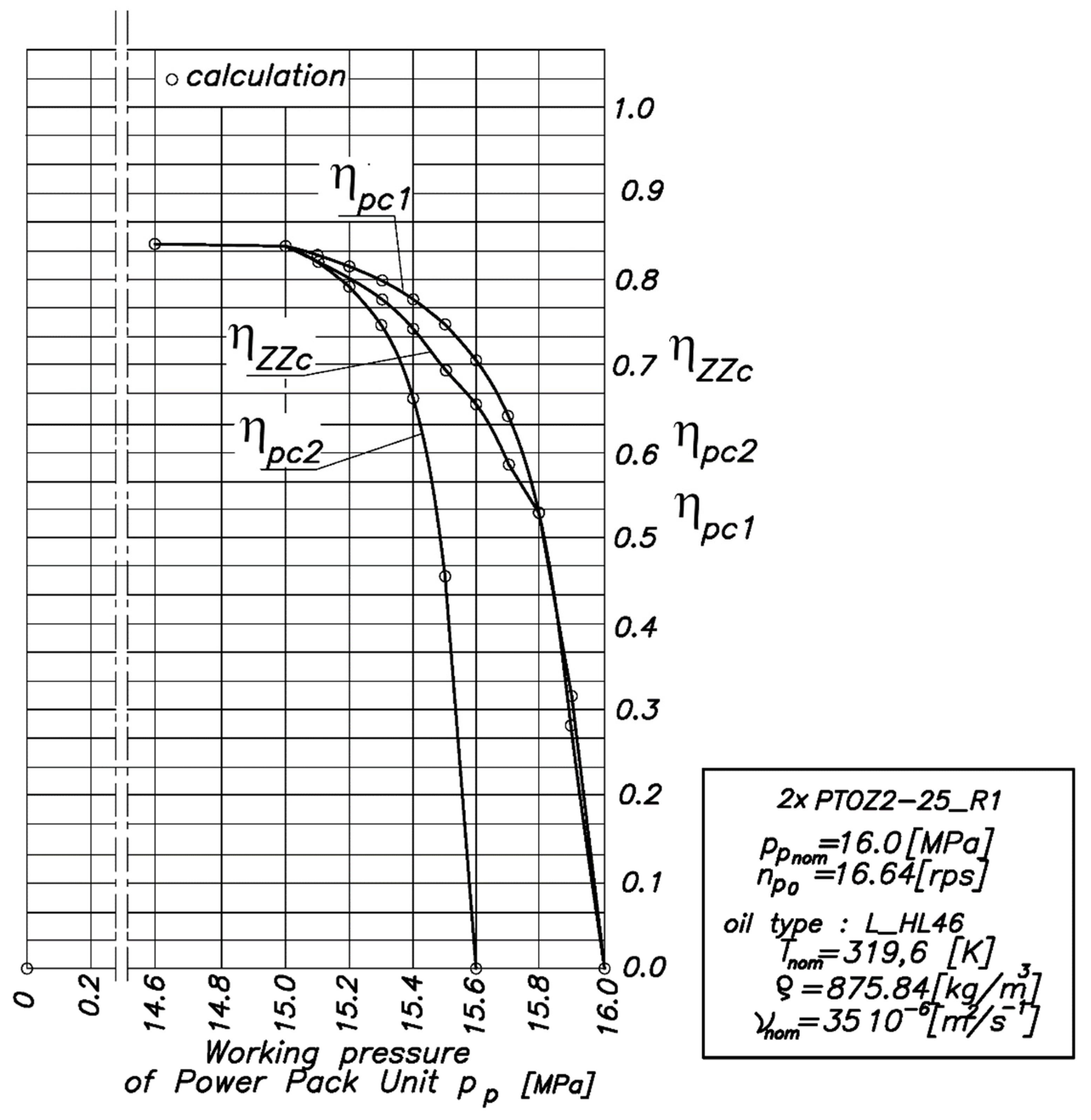
5. Efficiency of the Hydraulic Power Pack Unit with Twin-Two-Axial Piston Hydraulic Pumps in the Case of Simultaneous Work in an Open Circuit

In order to analyze the effect of the disproportionate capacity of individual positive displacement pumps on the total efficiency of a multi-pump power unit, a basic hydraulic system with two twin positive displacement pumps with variable specific capacities equipped with constant-pressure controllers was adopted (Figure 5). The analysis was carried out by means of a numerical experiment, assuming computational models of the individual pumps, presented in the previous subsections. Parallel operation of positive displacement pumps in an open system was assumed. Subsequently, the above steps were performed for a system consisting of two positive displacement pumps.
The total efficiency η ZZc of a power unit operating in an open system can be defined as the ratio of the useful power received from the entire power unit (the power of the hydraulic oil stream generated by all positive displacement pumps) to the total mechanical power supplied to the system (i.e., to the drive shafts of the pumps):
η ZZc   =   i = 1 2 N upi i   =   1 2 N pi   =   i   =   1 2 Q pi Δ p pi i   =   1 2 M pi ω pi   =   Q p 1 Δ p p   +   Q p 2 Δ p p M p 1 ω p 1   +   M p 2 ω p 2
where
Nupi—the useful power of the i-th pump of the power pack unit;
Npi—the driving power of the i-th pump of the power unit.
Using the block diagram of the two-pump power system (Figure 5b) and relation (6), one can write the following:
M p 1 ω p 1   =   Q p 1 Δ p p η pc 1 ;   M p 2 ω p 2   =   Q p 2 Δ p p η pc 2
After substituting relationship (20) into (19), it can be written as follows:
η ZZc   =   Q p 1 Δ p p   +   Q p 2 Δ p p Q p 1 Δ p p η pc 1   +   Q p 2 Δ p p η pc 2 = ( Q p 1   +   Q p 2 ) η pc 1 η pc 2 Q p 1 η pc 2   +   Q p 2 η pc 1
where
  • η pc 1 , η pc 2 —the total efficiency of the individual pumps of the power units.
For the purpose of carrying out a numerical analysis of the effect of the phenomenon of disproportionality of the performance of individual positive displacement pumps on the total efficiency of a multi-pump supply unit, it was first assumed that the supply unit consisted of two variable displacement piston-axial pumps of the PTOZ2-25R1 type produced by Hydral Wroclaw, analyzed earlier in Section 3 of this paper. It was assumed that the two pumps were characterized by linear control characteristics of constant-pressure controllers (pump no. 1 and no. 2). Both pump regulators were set so that a common control setting was established at the discharge pressure of all pumps: p p | α   =   15.5 °   =   15.0 [MPa]. This means that, at pressure pp = 15.0 [MPa], the deflection angles of all pumps’ swashplates were the same, as follows: α 1   =   α 2   =   15.5 ° (22).
According to Figure 6, for pump no. 1, the swing angle α 1 linearly decreases, obtaining a zero value at a nominal pressure pp = 16.0 MPa The control characteristics of the constant-pressure controller are similar for pump no. 2, with the difference that the zero setting of the pump’s working volume ( α 2   =   0 ° ) is obtained at a discharge pressure pp = 15.6 MPa, = at a pressure 0.4 MPa lower with respect to pump no. 1 (see Figure 3b). The diagram in Figure 5 shows the results of calculations of the cooperation of the two positive displacement pumps in one power pack unit. The total efficiency of the two pumps η pc 1 , η pc 2 and the entire power unit η ZZc is equal to each other, only for the pressure range:
p p     15.0   MPa
As the discharge pressure of the power unit pp increases, the difference between the total efficiency values of the two positive displacement pumps and the entire power unit increases. The maximum difference between the total efficiency η pc 1 of pump no. 1 and the total efficiency η ZZc of the power pack unit in the standard operation range of the power unit of 15.0 Mpa p p 16.0 MPa was 0.116 (11.6%). This proves that, described in the introduction, the frequent assumptions made by designers of multi-pump power systems, simplifying the model of the unit as a simple sum of identical component pumps, can lead to sizable errors in the calculation of the resulting total efficiency of the power unit. It should also be noted that, in the analyzed case, for pressure range,
15.6   MPa p p 16.0   MPa
Resulting from adjusting pump no. 2 to zero capacity, the value of the total efficiency η ZZc of the whole power pack unit is less than the efficiency η pc 1 of pump no.1 alone. The maximum difference between the resulting efficiency of the analyzed pumping unit and the other pump unit consisting of two identical positive displacement pumps of type no. 1 (the simplification often used in the scientific literature) was as high as 0.886 10 4 ( m 3 / s ) (5.3 (L/min)), which accounted for 38.1% of the total efficiency of the unit consisting of two hydraulic pumps of type no. 1. This was the result of differences in the control of the geometric volume settings of the component pumps owing to differences in the control characteristics of the regulators of the two analyzed hydraulic pumps.

6. Conclusions

The analysis of the performance of a hydraulic power unit consisting of two twin positive displacement pumps equipped in individual pressure regulators of the DP type, operating in an open system, carried out in this article allows the following conclusions.
The total efficiency of a twin-two-pump hydraulic power pack unit with pumps equipped in constant pressure regulators with different linear performance characteristics, operating in an open circuit system, is not equal to the total efficiency of the individual positive displacement pumps.
As a result of the different linear control characteristics of the p = constant regulators of the component positive displacement pumps included in the power pack unit, individual pumps can operate at the same pressure with different swash plate inclinations, that is, with different settings of the geometric value of the volume ep and with different resulting flow and energy efficiency.
Simplifying the assumptions often found in the literature that the component positive displacement in a twin-two-pump hydraulic power pack unit operating with the same capacity, load, and energy efficiency can lead to significant errors in assessing the actual efficiency of the entire supply unit and its individual component positive displacement pumps. Therefore, for improved accuracy, it is advisable not to make this type of simplification of replacing the operation of two positive displacement pumps with a single resultant pump when analyzing the energy efficiency of the power pack unit.

Author Contributions

Conceptualization, A.B. and R.P.; methodology, A.B. and R.P.; Software, A.B. and R.P.; Validation, A.B. and R.P.; Formal analysis, A.B. and R.P.; Investigation, A.B. and R.P.; Resources, A.B. and R.P.; Data curation, A.B. and R.P.; Writing—original draft preparation, A.B., R.P., M.A. and M.R.; Writing—review and editing, A.B., R.P., M.A. and M.R.; Visualization, A.B. and R.P.; Supervision, A.B. and R.P.; Funding acquisition, A.B. and R.P. All authors have read and agreed to the published version of the manuscript.

Funding

This paper is funded by the University “Union-NikolaTesla”, Faculty of Information Technology and Engineering.

Institutional Review Board Statement

Not applicable.

Informed Consent Statement

Not applicable.

Data Availability Statement

Data are contained within the article.

Acknowledgments

The authors would like to thank Editor-in-Chief, Editor, and anonymous reviewers for their valuable reviews.

Conflicts of Interest

The authors declare no conflict of interest.

References

  1. Banaszek, A.; Petrovic, R. Problem of Non Proportional Flow of Hydraulic Pumps Working with Constant Pressure Regulators in Big Power Multipump Power Pack Unit in Open System. Tech. Gaz. 2019, 2, 294–301. [Google Scholar]
  2. Banaszek, A. Identification of optimal efficiency exploatation conditions of axial piston hydraulic motor A2FM type using Artificial Neural Network algorithms. Elsevier Procedia Comput. Sci. 2021, 192, 1532–1540. [Google Scholar] [CrossRef]
  3. Stocznia Szczecinska Design Office SA. Technical Specification 40000 DWT Chemical Tanker Nr B578-I-PK/0050-1-“B”; Stocznia Szczecinska SA: Szczecin, Poland, 1997. [Google Scholar]
  4. Banaszek, A.; Petrovic, R. Calculation of the unloading operation in case of liquid cargo service with high density on modern product and chemical tankers equipped with hydraulic submerged cargo pumps. Stroj. Vestn. -J. Mech. Engin. 2010, 56, 186–194. [Google Scholar]
  5. Banaszek, A. The concept of powering of submerged ballast pumps from hydraulic central loading system on board product and chemical tankers. Mar. Technol. Trans. Pol. Acad. Sci. 2007, 18, 5–17. [Google Scholar]
  6. Bosch Rexroth Group. Catalogue RD 92050/09.21; Bosch Rexroth Group: Lohr am Main, Germany, 2021. [Google Scholar]
  7. Nollau, R. Interaction of circuits in the central power supply. Hydraul. Pneumatyka 1986, 1, 3–8. [Google Scholar]
  8. Petrovic, R. Mathematical Modeling and Identification of Multicylindrical Axial Piston Pump Parameters. Ph.D. Thesis, Faculty of Mechanical Engineering, Belgrade, Serbia, 1999. [Google Scholar]
  9. Halusiak, S. Dynamics of the Lifting Mechanism with Hydrostatic Drive from a Saturated Hydraulic Network with Automatic Control of the Absorption of the Secondary Motor. Ph.D. Thesis, Faculty of Mechanical Engineering KMRNiS, Technical University Lodz, Lodz, Poland, 2004. [Google Scholar]
  10. Śliwiński, P. Determination of the Theoretical and Actual Working Volume of a Hydraulic Motor—Part II (The Method Based on the Characteristics of Effective Absorbency of the Motor). Energies 2022, 14, 1648. [Google Scholar] [CrossRef]
  11. Sledziewski, P.; Śliwiński, P. The methodology of design of satellite working mechanism of positive displacement machine. Sci. Rep. 2022, 12, 13685. [Google Scholar] [CrossRef]
  12. Ivantysyn, J.; Ivantysynova, M. Hydrostatic Pumps and Motors. Principles, Design, Performance, Modelling, Analysis, Control and Testing, 1st ed.; Akademia Books International: New Delhi, India, 2001. (In English) [Google Scholar]
  13. Watton, J. Fluid Power Systems. Modelling, Simulation, Analog and Microcomputer Control; Longman Higher Education; Prentice Hall: New York, NY, USA; London, UK; Toronto, Canada; Sydney, Australia; Tokyo, Japan, 1989. [Google Scholar]
  14. Wu, X.; Chen, C.; Hong, C.; He, Y. Flow ripple analysis and structural parametric design of a piston pump. J. Mech. Sci. Technol. 2017, 31, 4245–4254. [Google Scholar] [CrossRef]
  15. Todić, N.; Savić, S.; Gordić, D.; Petrović, R. Experimental Research of the Hydrodynamic Processes of an Axial Piston Water Hydraulic Pump. Machines 2022, 10, 728. [Google Scholar] [CrossRef]
  16. Karpenko, M.; Bogdevcius, M. Investigation into the hydrodynamic processes of fitting connections for determining pressure losses of transport. Transport 2020, 35, 108–120. [Google Scholar] [CrossRef] [Green Version]
  17. Bury, P.; Stosiak, M.; Urbanowicz, K.; Kodura, A.; Kubrak, M.; Malesinska, A. A Case Study of Open- and Closed-Loop Control of Hydrostatic Transmission with Proportional Valve Start-Up Process. Energies 2022, 15, 1860. [Google Scholar] [CrossRef]
  18. Schlosser, W.M.J.; Hilbrands, J.W. Das theoretische Hubvolumen von Verdrangerpumpen. Olhydraulik Und Pneum. 1963, 7, 133–138. [Google Scholar]
  19. Schlosser, W.M.J.; Hilbrands, J.W. Das volumetrische Wirkungsgrad von Verdrangerpumpen. Olhydrauli Und Pneum. 1963, 7, 476–496. [Google Scholar]
  20. Williamson, D.P.; Shmays, D.B. The Design of Approximation Algorithms; Cambridge University Press: Cembridge, UK, 2011. [Google Scholar]
  21. Mathworks Inc. Matlab ver. R2020b Update 4 (9.9.0.15700001) 64-bit (win64). In Tutorial Book; Mathworks Inc.: Natick, MA, USA, 2020. [Google Scholar]
Figure 1. Typical view on the hydraulic twin-two-pump power pack unit on board of the sea ship. Source: shipyard’s own documentation.
Energies 15 08100 g001
Figure 2. Idea diagram of a pressure constant pump regulator DP. Source: own preparation based on Bosch Rexroth catalogue [6].
Energies 15 08100 g002
Figure 3. (a,b) Linear control characteristics of the DP-type constant-pressure pump regulator for both positive displacement pumps. Source: own preparation.
Energies 15 08100 g003
Figure 4. Universal diagram of the dependence of the total efficiency coefficient in the coordinates of the relative load coefficient and the geometric setting of the working volume for the piston-axial pump with a pivoting thrust disc of the PTOZ2-25-R1 type, produced by PZL HYDRAL Wroclaw. Source: own preparation.
Energies 15 08100 g004
Figure 5. Diagram of a hydraulic supply system with two pumps of variable specific capacity operating in an open circuit. P—pressure connection to the supply unit, R—connection of the supply unit to the return system. (a) Simplified hydraulic diagram and (b) block diagram. Source: own preparation.
Energies 15 08100 g005
Figure 6. Results of numerical calculations of the dependence of the total efficiency of a twin-two-pump power pack unit, operating in an open system, consisting of two pumps of the PTOZ2-25-R1 type, with assumed linear characteristics of the pump constant-pressure regulators in the function of the power pack unit working pressure ratio pp. Source: own preparation.
Energies 15 08100 g006
Table 1. The main technical parameters of the experimental tested piston pump PTOZ2-25-R1 produced by PZL-Hydral Wrocław Poland.
Piston Pump TypeElectric Motor Typeqptmaxppnomnp0Qptmax = qptmax• np0Mptnom = qptmax• ppnom/2π
•10−3 m3/rotMParps•10−3 m3/sNm
PTOZ2-25-R1Sg160M-40.0164916.016.640.274441.99
Publisher’s Note: MDPI stays neutral with regard to jurisdictional claims in published maps and institutional affiliations.

