Abstract
The main advantages of multi-winding (multiphase) induction machines include reducing torque ripple, decreasing rotor harmonics losses, reducing the current per phase without increasing the voltage per phase, reducing the current harmonics of the DC voltage source, and high fault tolerance. The authors propose a theoretical description for the harmonic content of the DC-link current, magnetomotive force, and electromagnetic torque of a multi-winding induction machine (IM), and an account of the interaction of the time harmonics for the power supply and the spatial harmonics for winding functions is presented. The proposed theoretical analysis has made it possible to substantiate supply-winding schemes for the compensation of higher harmonics (6th and 12th in the DC-link current and the IM’s electromagnetic torque) and the improvement of the electromagnetic and electromechanical compatibility of the multi-winding machine, which are justified according to the proposed theoretical description. Further, a schematic solution for the multi-winding induction motor with electronic changing of the pole number is proposed to provide a reduction in speed ripples at low rotation speeds. This decrease is ensured by increasing the number of pole pairs and increasing the frequency of the supply voltage. Mathematical models of multi-winding switch control-based induction machines are developed using the method of average voltages in the integration step for an investigation of electromagnetic and electromechanical processes. It is shown that the developed models are distinguished by high speed of response and accuracy. This is confirmed by the comparative analysis using known methods and models in the Matlab environment, as well as a comparison of the simulation results with the known results of physical experiments. The results of mathematical modeling show that the use of a multi-winding IM with appropriate supply-winding schemes stands to significantly reduce the ripples of the IM’s electromagnetic torque and DC-link current in the case of using six-step voltage source inverters. This makes this type of inverter suitable for use in a frequency-controlled electric drive as an alternative to using a PWM inverter, which has a negative influence on the IM’s state.
1. Introduction
Different types of multi-winding (multiphase) machines include multiphase induction machines, multiphase synchronous permanent magnets, and synchronous reluctance machines [1,2,3]. According to the phase number of multiphase machines, there are five-phase, six-phase, nine-phase, and fifteen-phase electric machines [3,4,5].
The main advantages of multiphase induction machines over three-phase inductions machines include reducing torque ripple, decreasing rotor harmonics losses, reducing the power/current per phase without increasing the voltage per phase, reducing the current harmonics of the DC voltage source, and high fault tolerance [6,7,8]. The reduced torque ripple and rotor harmonics losses are inherent for the multiphase induction machine that is supplied by six-step Voltage Source Inverters (VSIs) with limited switching frequency capability [1,9]. These advantages are still valid nowadays for very high-power applications. In the case of using the pulse-width modulation (PWM) of VSIs, control of the VSI output-current harmonic content is enabled [10].
Multi-phase induction motor drive allows for dividing the controlled power on more inverter legs, reducing the rated current of power electronic switches in high-power applications such as electric ship propulsion, high-power pumps, and aerospace applications [11].
In the multi-phase induction motor drive, it is possible to reduce the current harmonics of the DC-link capacitor filter and the capacitor size and cost, respectively, especially for a six-step VSI [8]. In the case of PWM operation of a VSI, a multi-phase machine solution allows for a reduction in the DC-link current harmonics [12,13].
Another important advantage of multi-phase induction machines is a high fault tolerance, which means that the multi-phase machine can start and run with one or more phase faults (open-phase or short-circuit fault) [14,15,16,17]. There are different strategies for multi-phase machine operation in the fault mode, such as minimum copper loss, maximum torque, predictive current control, and proportional resonant control [16,17,18].
One type of multi-winding induction machine is the six-phase induction machine (6PIM). A 6PIM with two three-phase windings is considered in this paper. These machines have different names, including dual three-phase, 6PIM, split-phase, dual-star, or asymmetrical 6PIM [6,9,10].
The 6PIM has two sets of three-phase windings (ABC and XYZ), spatially shifted by angle β. There are three types of three-phase winding connections in the 6PIM (Figure 1) according to [15]:
- D3: dual three-phase machine (β = 0°);
- A6: asymmetrical 6PIM (β = 30°);
- S6: symmetrical 6PIM (β = 60°).
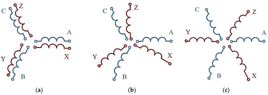
Figure 1.
Dual three-phase induction machine D3 for β = 0° (a); asymmetrical six-phase induction machine A6 for β = 30° (b); symmetrical six-phase induction machine S6 for β = 60° (c).
The main advantages of multiphase machines according to [7,8] are the following: reduced torque ripple frequency, reduced power/torque per phase, reduced spatial mmf harmonics, and continued operation after an open-phase fault.
Improvement of the electromagnetic capability is very important for electric vehicles. Namely, the DC-link harmonic currents cause an increase in battery temperature and a decrease in battery lifetime [19]. In [20], a six-phase inverter with a new sinusoidal PWM strategy is proposed to decrease DC-link harmonics and, consequently, to improve the electromagnetic capability of the IM.
In [21], a six-phase pole-change induction motor is proposed to provide a high torque at low speed ranges and a wide range of constant power operation for electric vehicles. Such a decision provides a reduction in torque fluctuation in the case of pole change. It is achieved by changing (increasing/decreasing) the current of each pole with an exponential function.
The work in [22] shows that a six-phase pole-change machine offers a wide-speed flux-weakening region with a low pole number and a high peak torque capability when operated with a high number of poles. It provides improved torque capability for the induction motor.
The paper in [23] shows that when operating with a lower number of poles, due to the reduction in the spatial angular separation between the three-phase winding of the six-phase electronic pole-changing winding induction machine, a third harmonic current injection is possible and results in enhanced torque capability and an increased flux-weakening region of operation.
The purpose of this research is to develop (a) a theoretical analysis of the harmonic content for the DC-link current, magnetomotive force (MMF), and electromagnetic torque of a multi-winding induction machine while taking into account the interaction of the time harmonics for the power supply and the spatial harmonics for winding functions; (b) an analytical justification based on winding power schemes for the compensation of higher harmonics and the improvement of electromagnetic and electromechanical compatibility of the multi-winding machine; and (c) a mathematical model for the investigation of electromagnetic and electromechanical processes in switch-controlled multi-winding IMs.
To achieve this purpose, a theoretical analysis of the harmonic content for the DC-link current of a switch-controlled induction machine is presented in Section 2. A theoretical analysis and an analytical description of the interaction between the time harmonics of the power supply and the spatial harmonics of the winding function and the latter’s influence on the forming of the MMF and the electromagnetic torque is presented in Section 3. The proposed analysis is based on the general ideas and approaches of Professor Omelyan Plakhtyna (1950–2021). These approaches are described in [24] and are developed in this research. The analytical description of the high harmonic compensation of the DC-link current, the MMF, and the electromagnetic torque of the multi-winding IM based on the theoretical analysis, as well as a justification for corresponding scheme solutions and their parameters are given in Section 4. A scheme for a four-winding IM with a reduced spatial harmonic content and high harmonics of the DC-link current is proposed, in which, in addition, electronic pole-pair change provides for a reduction in speed ripples. Mathematical models of switch-controlled multi-winding IMs based on the average-voltage-in-integration-step (AVIS) method are described in Section 5. The efficiency of the AVIS method is demonstrated in comparison with other known methods in Matlab. The adequacy of the models is proved by comparing the simulation results with results obtained using existing Matlab/Simulink models, as well as by comparing the simulation results with known results of physical experiments (for single-winding and double-winding IMs). Section 6 presents the simulation results, which are illustrated processes for the electromagnetic and electromechanical capabilities of double-winding and four-winding IMs.
The contributions of the paper are the following: a proposed theoretical description of the harmonic content for the DC-link current and the electromagnetic torque of a switch-controlled IM based on the interaction between the time harmonics of the power supply and the spatial harmonics of the winding function; a theoretical substantiation (based on the proposed theoretical description) of scheme solutions for high harmonic compensation of the DC-link current, the MMF, and the electromagnetic torque of the multi-winding IM, as well as an increase the electromagnetic and electromechanical compatibilities; and a new mathematical model of a switch-controlled multi-winding IM based on the AVIS method. The advantages of this method for the modeling of an IM in the sense of high speed of response and accuracy are shown.
2. Time Harmonics Interaction
The switch converter (inverter), which supplies a single winding three-phase IM (3PIM) (Figure 2), is described by conduction functions. The conduction function for each phase , , is equal to “1” when the semiconductor switch of the upper group is in the “ON”-state; is equal to “−1” when the semiconductor switch of the lower group is in the “ON”-state; and is equal to zero when the switches of this phase are “OFF”. This functions for the six-step VSI with a switch conduction of 120 electrical degrees is shown in Figure 3. It should be noted that a six-step VSI can operate with a switch conduction of 180 electrical degrees.
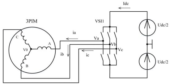
Figure 2.
Block diagram of switch control-based IM.

Figure 3.
Conduction functions of VSI phases.
Taking this into account, the potential of the corresponding phases of the VSI are determined as follows:
The input power of the switch control-based IM is determined according to the next formula (neglecting losses in the inverter):
where uA, uB, uC, iA, iB iC—voltages and currents of the IM’s phases.
The expression (2) for the input power, taking into account Formula (1), is written:
After performing the transformation, and taking into account that the sum of currents for winding connected in star without neutral wire is equal to zero, the expression for the input power is written:
The DC-link current is determined by currents of the IM’s stator windings and conduction functions:
Taking into account , , , the expression for phase currents of the IM’s windings are written similarly:
Inverter conduction functions are periodic and can be decomposed into a Fourier series. A similar distribution can be made for phase currents of the windings. Then, the expression for the DC-link current is written:
It is known that there are no harmonics multiplied by three by a star-winding connection. Further, there are even no harmonics. To derive the expression describing the harmonic content of the DC-link current, we take into account the first, fifth, and seventh harmonics for the functions of conduction and the winding currents. Then, the functions of conduction are written as:
where .
The expressions for the phase currents are similar. Taking this into account, the formula for the DC-link current is written:
It follows from trigonometric transformations for any angles and :
Let us assume that the harmonic amplitudes are the same for all phases. Then, taking into account the formula for (9), the expression for the DC-link current is written:
Note that the harmonic content for the input power, the shaft power, and the electromagnetic torque of the 3PIM is similar to the DC-link current.
According to the analysis of the expression (11), we can draw the following conclusions regarding the interaction between the time harmonics of the current and the inverter conduction functions.
1. The interaction of same-order harmonics provides a constant component for the DC-link current, the input power, the shaft power, and the electromagnetic torque. Such a case will take place by sinusoidal currents of 3PIM windings and sinusoidal conduction functions (inverter with PWM).
2. The interaction between the first harmonic of the current and fifth and seventh harmonics of the conduction functions leads to the appearance of the sixth harmonic of the DC-link current, the input power, the shaft power, and the electromagnetic torque. The interaction between the first harmonic of the conduction functions and the fifth and seventh harmonics of the currents provides the same results.
3. The interaction of the fifth and seventh harmonics of the conduction functions and currents leads to the appearance of the 12th harmonic of the DC-link current, the input power, the shaft power, and the electromagnetic torque.
By means of similar mathematical expressions, it is possible to show that:
4. The interaction between the 1st harmonic of the current and 11th and 13th harmonics of the conduction functions leads to the appearance of the 12th harmonic of the DC-link current, the input power, the shaft power, and the electromagnetic torque. The interaction between the 1st harmonic of the conduction functions and the 11th and 13th harmonics of the currents provides the same results.
5. The interaction of the 11th and 13th harmonics of the conduction functions and currents leads to the appearance of the 24th harmonic of the DC-link current, the input power, the shaft power, and the electromagnetic torque.
6. The interaction of the harmonics higher than the 13th harmonic can be ignored due to the value of the amplitude product being too small.
3. Time and Spatial Harmonics Interaction
The MMF of the 3PIM in the air gap is created by the current, which follows through the winding. Winding coils are generally distributed non-sinusoidally in space. In this case, the winding current is determined by the DC-link current and the conduction functions of the inverter. The function of the coil distribution in space w(η) for the diametric winding has an addition to the first harmonics and also higher odd harmonics that are no multiplex of three. In this case, the MMF is determined by the interaction between the time harmonics of the current (conduction functions of inverter) and the spatial harmonics of the winding function.
Taking into account the first, fifth, and seventh spatial harmonics of the winding function and the relevant time harmonics of the 3PIM current, the MMFs for the ABC-phases of the IM are written:
where η—spatial angle in electric degrees; w1, w5, w7—magnitude of the winding function’s harmonics (w1 = 4w/π, w—number of coils).
The resultant MMF of the 3PIM in the air gap is written:
Taking into account the Formula (10), the MMF of the ABC three-phase winding is equal to:
The MMF of the 3PIM has time and spatial harmonics according to expression (14).
In the case of a sinusoidal disturbance of the winding coils in space and the sinusoidal conduction functions of the inverter (using PWM), the MMF in the air gap is equal to:
The MMF amplitude (in the case of ) is constant and is determined by the value of the DC-link current and the number of winding coils.
In the general case, the MMF amplitude in the air gap is written:
The following conclusions can be drawn from Equation (16):
1. The interaction of the time and spatial harmonics of unequal order leads to ripples in the MMF amplitude. In this case, the interaction between the first time harmonic of the inverter conduction functions (IM current) and the fifth and seventh spatial harmonics of the winding functions leads to the appearance of the sixth harmonic of the MMF amplitude.
2. The interaction between the fifth and seventh spatial harmonics of the winding functions and the fifth and seventh time harmonic of the conduction functions (IM current) leads to the appearance of the 12th harmonic of the MMF amplitude.
By means of similar mathematical expressions, it is possible to show that:
3. The interaction between the 1st time harmonic of the inverter functions of conduction (IM current) and the 11th and 13th spatial harmonics of the winding functions leads to the appearance of the 12th harmonic of the MMF amplitude. The interaction between the first harmonic of the winding functions and the fifth and seventh harmonics of the inverter functions of conduction (IM current) provides the same results.
4. The interaction between the 11th and 13th spatial harmonics of the winding functions and the 11th and 13th time harmonics of the inverter functions of conduction (IM current) leads to the appearance of the 24th harmonic of the MMF amplitude.
5. The interaction of the time and spatial harmonics higher than the 13th harmonic can be ignored due to the value of the amplitude product being too small.
Note that ripples in the MMF amplitude lead to ripples in the IM’s magnetic flux and the electromagnetic torque. In the case of sinusoidal supply currents of the IM, the electromagnetic torque has, in addition, the 6th and 12th time harmonics due to the 5th, 7th, 11th, and 13th spatial harmonics of the MMF winding.
4. Methods of Electromagnetic Compatibility Improvement
4.1. Time Harmonics Compensation
To eliminate the high harmonics of the MMF and the input power, multi-winding and multiphase IMs are used.
The dual-winding IM (6PIM) has two sets of three-phase windings shifted by angle β (Figure 4). Each three-phase winding of the 6PIM is supplied by an individual inverter. The DC-link current is determined as the sum of the input currents of VSI1 and VSI2.
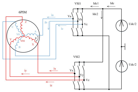
Figure 4.
Block diagram of switch control-based dual-winding IM.
Let VSI2 conduction functions be shifted relative to VSI1 conduction functions by angle α in this scheme; then, taking into account the first, fifth, and seventh harmonics, the expressions for VSI2 conduction functions are written:
The phase currents for the XYZ-winding of the 6PIM are determined as:
Accordingly, the input current of VSI2, similar to expression (9), is written:
Taking into account Formula (10), the expression for the input current of VS2 is written:
Taking into account Formulas (11) and (20), the DC-link current is determined as:
To compensate for the sixth harmonic of the DC-link current and, accordingly, the input power, the following conditions must be met:
To fulfill the conditions of Formula (22), it is necessary that the displacement of the XYZ-winding currents relative to the ABC-winding currents and conduction functions of VSI1 and VSI2 is equal to 30 electrical degrees (). Then, the nearest higher harmonic of the DC-link current will be the 12th, according to the expression:
Thus, the displacement of the XYZ-winding currents and the inverter conduction functions by 30 electrical degrees provides the compensation for the sixth harmonic of the DC-link current and the IM’s input power. There is the 12th harmonic of the DC-link current and the IM input power, which is the result of the interaction of the 1st harmonic of the conduction functions with the 11th and 13th harmonics of the current, the 1st harmonic of the current with the 11th and 13th harmonics of the conduction functions, as well as the 5th and 7th harmonics among themselves. This is explained by the appearance of the components (24) in the current expression.
The four-winding IM (12-phase IM) is used for compensation of the 12th harmonic (Figure 5). Let us demonstrate this using an example of the interaction of the 1st, 5th, 7th, 11th, and 13th harmonics of the conduction functions with the 1st harmonic of the currents. The interaction of the 1st, 5th, 7th, 11th, and 13th harmonics of the currents with the 1st harmonics of the conduction functions will give a similar result.
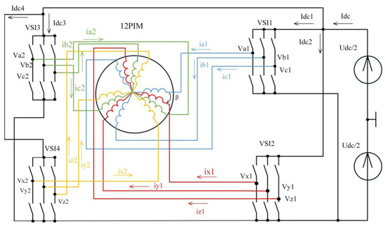
Figure 5.
Block diagram of switch control-based four-winding IM.
The input currents of VSI1, VSI2, VSI3, and VSI4 are determined according to expression (25):
where α1—the phase shift between VS2 conduction functions and VS1 conduction functions, α2—the phase shift between VS3 conduction functions and VS1 conduction functions, α3—the phase shift between VS4 conduction functions and VS1 conduction functions.
In order to eliminate the sixth harmonic of the DC-link current and, accordingly, the input power, the following conditions must be met:
To fulfill the conditions of Formula (26), taking into account that for any α, it is necessary that the displacement for the currents of the 12PIM’s corresponding windings and the VSI1, VSI2, VSI3, and VSI4 functions of conduction be equal to 15 electrical degrees ( ).
In order to eliminate the 12th harmonic of the DC-link current and, accordingly, the input power, the following conditions must be met:
To fulfill the conditions of Formula (27), taking into account that for any α, it is necessary that the displacement for the currents of the 12PIM’s corresponding windings and the VSI1, VSI2, VSI3, and VSI4 functions of conduction be equal to 15 electrical degrees ( ).
Thus, the displacement of the windings in the 12PIM by an angle of 15 electrical degrees provides the elimination for 6th and 12th harmonics of the input power (current).
4.2. Spatial Harmonics Inclunding
Next, the process of MMF formation in a multi-winding IM is considered, taking into account the interaction of the time and spatial harmonics.
Consider the dual-winding IM with a displacement of the ABC three-phase windings and the XYZ three-phase windings by the angle β in space (Figure 4). The MMF for the XYZ three-phase windings of the 6PIM supplied from an inverter with a displacement of conduction functions by phase angle α are determined similar to expression (13):
Taking into account the trigonometric Formula (10), the expression of the MMF for the XYZ three-phase windings of the 6PIM is written:
Taking into account , the MMF for the ABC and XYZ three-phase windings, which are shifted in space by β electric degrees, according to the Formula (14) is equal to:
In order to eliminate the harmonic content due to interaction of the fifth and seventh spatial harmonics of the winding function with the first time harmonic of the conduction functions (currents), the following conditions must be met:
Taking into account that and , we obtain from expression (31):
As a result, it is written: , .
In order to eliminate the harmonic content due to interaction of the fifth and seventh time harmonics of the currents with the first spatial harmonic of the winding function, the following conditions must be met:
Taking into account that and , we obtain from (33):
As a result, it is written: , .
Substituting in expression (30) , , we will get:
According to expression (35), there are no high harmonics of the MMF due to the interaction of the first spatial harmonic with the fifth and seventh time harmonics and the first time harmonic with the fifth and seventh spatial harmonics (these harmonics have the largest amplitude and influence) in the case of the winding displacement of and the supply-voltage phase shift of . There are high harmonics due to the interaction of the fifth and seventh spatial and time harmonics, but their amplitudes are significantly smaller (determined by the product of the corresponding amplitudes of the fifth and seventh harmonics).
The amplitude of the MMF in this case is equal to:
According to expression (36), there is no 6th harmonic of the MMF amplitude; the nearest higher harmonic is the 12th. The corresponding harmonic content of the the IM’s electromagnetic torque is similar to the MMF amplitude.
4.3. Pole Changing of Multi-Winding IM
The reduction in the IM’s speed ripples in the case of the same ripples of electromagnetic torque is achieved by increasing the voltage frequency and the pole pairs.
The increasing of pole pairs p in a multi-winding IM for low rotation speeds allows for increasing the supply voltage frequency f for these speeds according to formula:
where Ω—rotation speed of the IM.
Assuming that the load torque of the IM is constant, the expression for the kth harmonic of the rotation speed is written:
In the general case, the amplitude of rotation-speed ripples caused by pulsations of the kth harmonic of the electromagnetic torque (k = 6, 12, 24) depends inversely proportionally on the frequency of the supply voltage according to expression (39).
where Ωkm—ripple amplitude of the kth rotation-speed harmonic, Tkm—ripple amplitude of the kth electromagnetic-torque harmonic.
It is proposed to use the schematic solution of the multi-winding IM with electronic changing of the pole number (Figure 6).
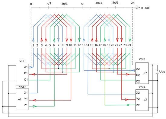
Figure 6.
Block diagram of switch control-based pole-changing multi-winding IM.
Such a multi-winding IM consists of two three-phase windings. Each winding consists of two sections shifted in space by 30 electric degrees, which are supplied from the VSI1, VSI2, VSI3, and VSI4 inverters.
The reduction in the IM’s speed ripples at low rotation speeds is ensured by increasing the number of pole pairs and increasing the frequency of the supply voltage. Pole-pair changing is realized by shifting, in time, the switch-conduction intervals of the VSI3 and VSI4 inverters relative to the VSI1 and VSI4 inverters by 180 electric degrees for one pole pair and without shifting for two pole pairs.
The MMF distribution of a multi-winding IM in space for one and two pole pairs is shown in Figure 7.
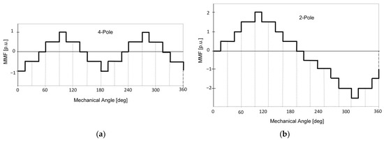
Figure 7.
MMF distribution of multi-winding IM in space for two pole pairs p = 4 (a) and for one pole pair p = 2 (b).
That is, rotation speed ripples caused by the kth harmonic of the electromagnetic torque are inversely proportional to the frequency of the supply voltages, namely, increasing the frequency reduces the amplitude of the velocity pulsations. Therefore, it is advisable to increase the pole number and frequency at a low rotation speed. This ensures the smooth movement of the IM at a low rotation speed.
5. Mathematical Model of Multi-Winding IM
A feature of the proposed mathematical model of the switch control-based multi-winding IM is using the method of the average voltages in the integration step (AVIS) [25,26,27]. This method has repeatedly been used by authors, and its high efficiency was demonstrated during a simulation of power schemes with synchronous machines and induction machines, as well as power systems with nonlinearities [26,28,29,30]. The advantages of the method are high calculation speed and numerical stability, which make it suitable for creating real-time models. These real-time models are able to work for a long time in interaction with physical objects (hardware-in-the-loop technology) [29,31,32].
The universal equation for an electrical branch, which contains active resistance R, inductance L, capacitance C, and source of the electromotive force (emf), is written according to the AVIS method [25] as:
where i0—branch current at the beginning of the integration step; m—order of the polynomial that describes the current curve in the integration step (order of the method); , —average values in the integration step of the branch voltage and electromotive force, uR0—voltage on the active resistance at the beginning of the integration step, uC0—voltage on the capacitor at the beginning of the integration step, ψ0, ψ 1—flux linkages at the beginning and at the end of the integration step, Δt—integration step.
The equation for a branch without capacity by the AVIS method of the first order according to expression (40) is written:
The equation for a branch without capacity by the AVIS method of the second order is written:
Equations (41) and (42) are the basis for forming the IM mathematical model.
5.1. Mathematical Model of IM Electric Cicuits by AVIS Method of the 1st Order
Taking into account that an increase in flux linkages in the integration step is determined as , according to expression (41), the vector equation for the stator and rotor windings is written:
where —vector of the average in the integration step values of applied voltages; —instantaneous values of applied voltages;, —vectors of currents at the beginning and the end of the integration step; —matrix of active resistances; , —matrix of inductances at the beginning and the end of the integration step, γR0, γR1—rotation angle at the beginning and the end of the integration step; —matrix of inductances, which for a 3PIM is equal to:
where —magnetizing inductance, which is a function of the magnetizing current in a case taking into account the IM’s nonlinearity, —stator leakage inductance, —rotor leakage inductance.
The equivalent circuit of the IM based on Equation (43) is shown in Figure 8.
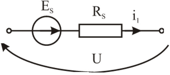
Figure 8.
Equivalent circuit of IM.
It is marked in Figure 8: —step electromotive force (determined by the value of the current and the electromagnetic parameters at the beginning of the integration step), —step resistance.
The vector of the IM currents at the end of the integration step according to the equivalent circuit of the IM (Figure 8) is determined as:
5.2. Mathematical Model of IM by AVIS Method of the Second Order
Taking into account that an increase in the flux linkages in the integration step is determined as , according to expression (42), the vector equation for the the stator and rotor windings is written:
In this case, the parameters of the IM’s equivalent circuit (Figure 8) are determined as: —step electromotive force (determined by the value of currents, their derivatives, and electromagnetic parameters at the beginning of the integration step), —step resistance.
The vector of the IM currents at the end of the integration step according to the equivalent circuit of the IM is determined similarly to the AVIS of the first order:
In order to determine the IM’s currents by the AVIS of the second order, the time derivatives of the currents are necessary (they are included in the expression for the step electromotive force). These derivatives are found from the equation:
Taking into account that the flux linkage in expression (48) is a function of the currents and the rotation angle, the time derivative of the flux linkage is determined as:
where p—number of the pole pair, Ω—rotation speed, —the electromotive force of transformation and the electromotive force of rotation (components of stator emf).
According to Formulas (48) and (49), the expression for the derivatives of currents is .
The matrix for the rotation-angle derivatives of inductances is equal to:
The expression for the rotation angle and rotation speed is written:
where TL—load torque, Te—electromagnetic torque of the IM, J—inertia.
The mathematical model of the multi-winding IM differs by the matrix of inductances , the dimensions of the currents, the voltages, and the flux-linkage vectors.
The matrix of inductances for the 6PIM is written:
where the matrix of the self and mutual inductances for the stator (s1 and s2) and the rotor (r) windings are:
The matrix of the mutual inductances between the stator windings is:
The matrix of the mutual inductances between the stator and the rotor windings is:
The matrix of inductance for the 12PIM is written:
Their components are the self and mutual inductances between the windings, which are determined similarly to the 6PIM.
5.3. An Effiency Analysis of AVIS Method for IM Modelling
To evaluate the efficiency of the AVIS method, a comparative analysis was conducted with other well-known numerical integration methods implemented using the Matlab function. The comparison was carried out for the starting mode of the induction motor, which is characterized by a significant range of coordinate changes. The IM parameters, which are used for modeling, are: motor type 2SIE315S2, PN = 110 kW, UN = 380 V, IN = 192 A, Lσ1 = L’σ2 = 0.00026 H, Lm = 0.012 H, R1 = 0.03 Ohm, R’2 = 0.03 Ohm, J = 1.5 kgm2.
The simulation result was taken as the etalon using a typical block of the IM from the Matlab/Simulink library (such a result is obtained using various Matlab fixed-step integration methods in the case of a small integration step corresponding to more than 100 points per period).
Simulation results for the IM’s starting mode using the etalon method (red waveform) and the AVIS method of the first and second order (blue waveform) are shown in Figure 9 and Figure 10. The AVIS methods of the first and second order provide the same result as the etalon method in the case of the integration step, i.e., 0.00028 s (70 points per period).
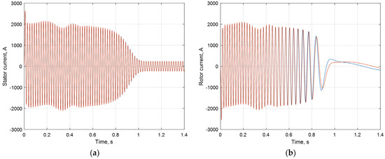
Figure 9.
Simulation results of the IM’s starting mode: stator current (a), rotor current (b)—etalon results (red), AVIS method of the 1st and 2nd order (blue).
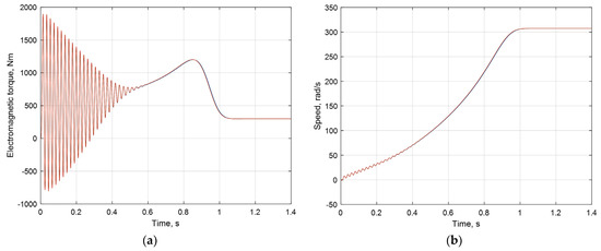
Figure 10.
Simulation results of the IM’s starting mode: electromagnetic torque (a), rotation speed (b)—etalon results (red), AVIS method of the 1st and 2nd order (blue).
The AVIS methods of the first and second order provide slightly different results in the case of an integration step of 0.0007 s (28 points per period). The AVIS method of the second order has a high accuracy (Figure 11).
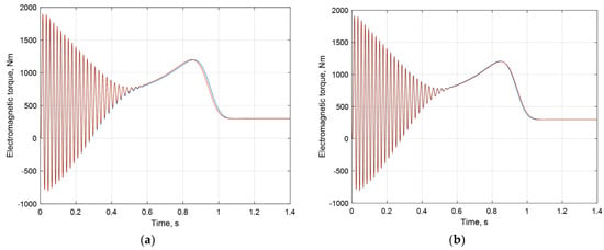
Figure 11.
Calculated electromagnetic torque of IM: AVIS method of the 1st order (blue) (a), AVIS method of the 2nd order (blue) (b), and etalon result (red).
A comparison of the IM’s electromagnetic torque for various Matlab integration methods in the case of an integration step equal to 0.0007 s is shown in Figure 12 and Figure 13.
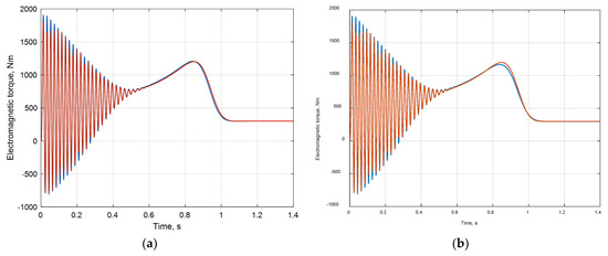
Figure 12.
Calculated electromagnetic torque of IM: Runge–Kutte method of the 5th order (ode5, blue) (a), Runge–Kutte method of the 4th order (ode4, blue) (b), and etalon result (red).
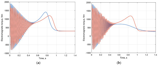
Figure 13.
Calculated electromagnetic torque of IM: Runge–Kutte method of the 3rd order (ode3, blue) (a), the improved Euler method (ode2, blue) (b), and etalon result (red).
According to the simulation results, the AVIS method of the second order provides the same result as the Runge–Kutte method of the fifth order, but it should be note that Runge–Kutte method requires more calculation in the integration step. All the other methods lose in accuracy.
The second indicator for the model efficiency is the calculation speed (performance). The calculation speed is compared for models implemented in the Matlab environment (for the AVIS 1, AVIS 2, Ode2, Ode3, Ode4, and Ode5 methods), as well as for models in Simulink (the Simulink model consisted of typical blocks—“Three-Phase Programmable Voltage Source” and “Asynchronous machine”—and used the Dormand–Prince (Ode45) method with the default precision setting). The comparison was carried out for a small step corresponding to 500,000 points per 1.4 s; in this case, all methods provide an equally accurate result. The results are presented in Table 1.

Table 1.
Speed of response for calculation time of 1.4 s corresponding to 500,000 points.
According to Table 1, the AVIS methods of the first and second order provide the highest calculation speed in comparison with all the analyzed methods with a fixed step, as well as the Dormand–Prince (Ode45) method with a variable step (the default precision setting are used).
Simulation results for the IM supplied from VSIs are compared with experimental data from [1]. Simulation and experimental results for stator current waveforms are shown in Figure 14 for the 3PIM and in Figure 15 for the 6PIM. The comparison of results allows us to claim an almost identical waveform, which means the identical harmonic content of stator-currents for the 3PIM and 6PIM in the case of the VSI’s supply. It confirms the adequacy of the description of electromagnetic intercoupling in the presented IM model.
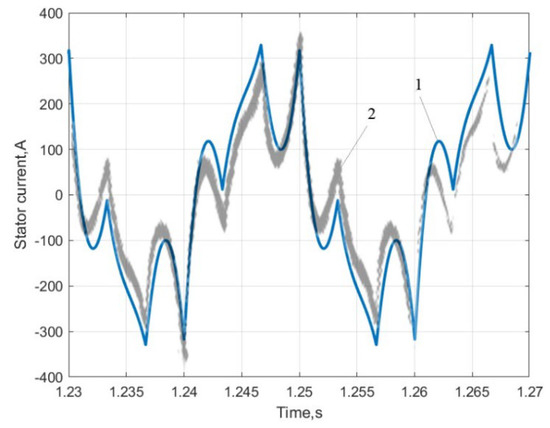
Figure 14.
Stator current of 3PIM in steady-state mode for the 6-step VSI supplying: 1—simulation, 2—experimental data adapted from [1].
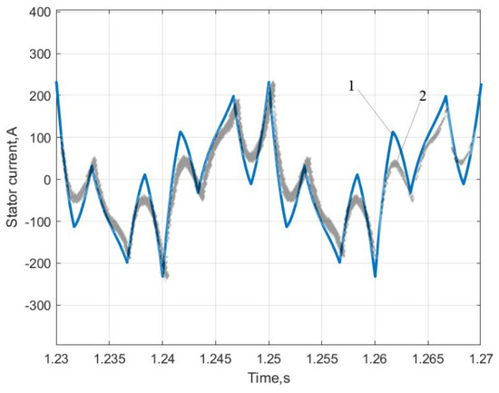
Figure 15.
Stator current of asymmetric 6PIM in steady-state mode for the 6-step VSI supplying: 1—simulation, 2—experimental data adapted from [1].
6. Simulation Results
The obtained results using the developed models illustrate a higher harmonic compensation of the DC-link current and the electromagnetic torque of the switch control-based IM in the considered schemes and confirm the theoretical conclusions. The waveforms of the stator and rotor currents are also given.
The DC-link current and the electromagnetic torque of the 3PIM supplied by the six-step VSI has the 6th and 12th harmonics (Figure 16).
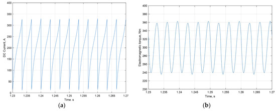
Figure 16.
DC-link current (a), electromagnetic torque (b) of 3PIM supplied by 6-step VSI in steady-state mode.
Using the 6PIM with a displacement of the three-phase windings in space by angle and the phase shift of the windings’ currents by angle provides the sixth harmonic elimination of the DC-link current (Figure 17a), the electromagnetic torque (Figure 17b), and the rotor currents (Figure 18b). In this case, there is 12th harmonic in their composition. The ripple amplitude of the DC-link current for the 6PIM is 1.18 times smaller compared to the 3PIM. The ripple amplitude of the electromagnetic torque for the 6PIM is six times smaller compared to the 3PIM.
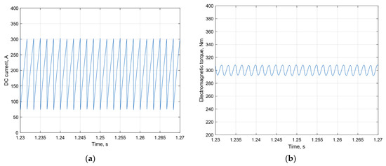
Figure 17.
DC-link current (a), electromagnetic torque (b) of 6PIM in steady-state mode.
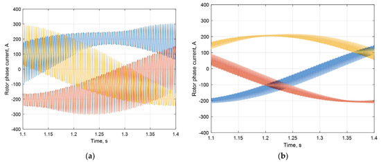
Figure 18.
Rotor currents of 3PIM (a), rotor currents of 6PIM (b) in steady-state mode: ph. A—blue, ph. B—red, ph. C—yellow.
Using the 12PIM with a displacement of the three-phase windings in space by angle and a phase shift of the windings’ currents by angle (Figure 19a) provides the 6th and 12th harmonic elimination in the DC-link current (Figure 20a), the electromagnetic torque (Figure 20b), and the rotor currents (Figure 19b).
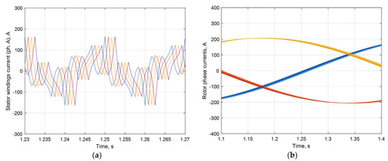
Figure 19.
Stator currents (a), rotor currents (b) of 12PIM in steady-state mode: ph. A—blue, ph. B—red, ph. C—yellow.
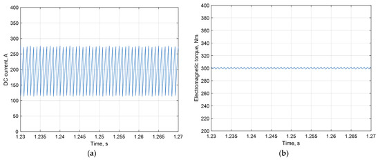
Figure 20.
DC-link current (a), electromagnetic torque (b) of 12PIM in steady-state mode.
The ripple amplitude of the DC-link current for the 12PIM is two times smaller compared to the 3PIM. The ripple amplitude of the electromagnetic torque for the 12PIM is 30 times smaller compared to the 3PIM.
7. Conclusions
The proposed theoretical description establishes the analytical dependencies of the harmonic composition for the DC-link current (input power), the MMF, and the electromagnetic torque on the interaction of the time harmonics for the power supply and the spatial harmonics for the winding functions. It allows us to theoretically substantiate scheme solutions for improving the electromagnetic and electromechanical compatibility of the multi-winding switch control-based IM by the elimination of high harmonics (6th and 12th) in the DC-link current and the IM electromagnetic torque. The decrease in the high harmonic content for the input power and the DC-link current improves the electromagnetic compatibility with the power source, and the reduction in ripples of the electromagnetic torque and the rotation speed improves the electromechanical compatibility of the IM with the load.
Mathematical models of multi-winding switch control-based IMs developed using the AVIS method are characterized by high speed of response and accuracy. This is confirmed by the comparative analysis using known methods and models in the Matlab environment, as well as the comparison of simulation results with the known results of physical experiments.
The use of a multi-winding IM with the appropriate supply-winding schemes provides for significantly reducing the ripples of the IM’s electromagnetic torque (6 times for the 6PIM and 60 times for the 12PIM) and the DC-link current (1.5 times for 6PIM and 2 times for 12PIM) in the case of using the six-step VSI. This increases electromagnetic and electromechanical compatibility and makes this type of inverter suitable for use in frequency-controlled electric drive as an alternative to using a PWM inverter, which has a negative influence on the IM’s state.
The increase in the IM’s pole pair at low rotation speeds by changing the switch-winding supply allows for reducing speed ripples in the case of the same ripples of electromagnetic toque and increasing the range of the speed regulation. The amplitude of the speed ripples is inversely proportional to the frequency of the supply voltage.
Author Contributions
Conceptualization, A.K., M.K. and M.S.; methodology, M.S. and P.B.; software, M.S. and J.K.; validation, M.K., A.L. and Z.Ł.; formal analysis, M.S.; investigation, A.K. and M.S.; resources, P.B. and J.K.; data curation, M.S. and A.L.; writing—original draft preparation, M.S.; writing—review and editing, A.K., A.L. and M.K.; visualization, M.S.; supervision, M.K.; project administration, P.B.; funding acquisition, M.K. All authors have read and agreed to the published version of the manuscript.
Funding
This research received no external funding.
Data Availability Statement
Not applicable.
Conflicts of Interest
The authors declare no conflict of interest.
References
- Abbas, M.A.; Christen, R.; Jahns, T.M. Six-Phase Voltage Source Inverter Driven Induction Motor. IEEE Trans. Ind. Appl. 1984, IA-20, 1251–1259. [Google Scholar] [CrossRef]
- Levi, E. Editorial—Special Issue on Multi-Phase Motor Drives. EPE J. 2004, 14, 4. [Google Scholar]
- Shchur, I.; Jancarczyk, D. Electromagnetic Torque Ripple in Multiple Three-Phase Brushless DC Motors for Electric Vehicles. Electronics 2021, 10, 3097. [Google Scholar] [CrossRef]
- Levi, E. Advances in converter control and innovative exploitation of additional degrees of freedom for multiphase machines. IEEE Trans. Ind. Electron. 2016, 63, 433–448. [Google Scholar] [CrossRef]
- Barrero, F.; Duran, M.J. Recent advances in the design, modeling and control of multiphase machines—Part 1. IEEE Trans. Ind. Electron. 2016, 63, 449–458. [Google Scholar] [CrossRef]
- Bojoi, R.; Farina, F.; Profumo, F.; Tenconi, A. Dual-Three Phase Induction Machine Drives Control—A Survey. IEEJ Trans. Ind. Appl. 2006, 126, 420–429. [Google Scholar] [CrossRef]
- Levi, E.; Barrero, F.; Duran, M.J. Multiphase machines and drives—Revisited. IEEE Trans. Ind. Electron. 2016, 63, 429–432. [Google Scholar] [CrossRef]
- Levi, E. Multiphase Electric Machines for Variable-Speed Applications. IEEE Trans. Ind. Electron. 2008, 55, 1893–1909. [Google Scholar] [CrossRef]
- Płachtyna, O.; Żarnowski, R.; Kłosowski, Z. Drive systems with an induction motor and an inverter, controlled without PWM supplied by tracking network. Kwart. Pojazdy Szyn. 2012, 2, 1–5. (In Polish) [Google Scholar]
- Boglietti, A.; Bojoi, R.; Cavagnino, A.; Tenconi, A. Efficiency Analysis of PWM Inverter Fed Three-Phase and Dual Three-Phase High Frequency Induction Machines for Low/Medium Power Applications. IEEE Trans. Ind. Electron. 2008, 55, 2015–2023. [Google Scholar] [CrossRef]
- Sun, C.; Ai, S.; Hu, L.D.; Chen, Y. The development of a 20MW PWM driver for advanced fifteen-phase propulsion induction motors. J. Power Electron. 2015, 15, 146–159. [Google Scholar] [CrossRef]
- Weisgerber, V. Double-pulse inverter feeds 6-phase asynchronous motor for harmonic loss reduction. In Proceedings of the Fifth European Conference on Power Electronics and Applications, Brighton, UK, 13–16 September 1993; pp. 39–44. [Google Scholar]
- Bojoi, R.; Caponet, M.C.; Grieco, G.; Lazzari, M.; Tenconi, A.; Profumo, F. Computation and measurements of the DC link current in six-phase voltage source PWM inverters for AC motor drives. In Proceedings of the Power Conversion Conference-Osaka 2002 (Cat. No.02TH8579), Osaka, Japan, 2–5 April 2002; IEEE: New York, NY, USA, 2002; pp. 953–958. [Google Scholar] [CrossRef]
- Guzman, H.; Gonzalez, I.; Barrero, F.; Durán, M. Open-Phase Fault Operation on Multiphase Induction Motor Drives. In Induction Motors—Applications, Control and Fault Diagnostics; IntechOpen: London, UK, 2015. [Google Scholar] [CrossRef]
- Munim, W.N.W.A.; Duran, M.J.; Che, H.S.; Bermúdez, M.; González-Prieto, I.; Rahim, N.A. A Unified Analysis of the Fault Tolerance Capability in Six-Phase Induction Motor Drives. IEEE Trans. Power Electron. 2017, 32, 7824–7836. [Google Scholar] [CrossRef]
- Parsa, L.; Toliyat, H.A. Fault-Tolerant Interior-Permanent-Magnet Machines for Hybrid Electric Vehicle Applications. IEEE Trans. Veh. Technol. 2007, 56, 1546–1552. [Google Scholar] [CrossRef]
- Guzman, H.; Duran, M.J.; Barrero, F. A Comprehensive Fault Analysis in a Five-Phase Induction Motor Drive with an Open Phase. In Proceedings of the 15th International Power Electronics and Motion Control Conference (EPE/PEMC), Novi Sad, Serbia, 4–6 September 2012; IEEE: New York, NY, USA, 2013; pp. 5–6. [Google Scholar] [CrossRef]
- Benbouzid, M.E.H.; Diallo, D.; Zeraoulia, M. Advanced Fault-Tolerant Control of Induction-Motor Drive for EV/HEV Traction Applications: From Conventional to Modern and Intelligent Control Techniques. IEEE Trans. Veh. Technol. 2007, 56, 519–528. [Google Scholar] [CrossRef]
- Mori, M.; Mizuno, T.; Ashikaga, T.; Matsuda, I. A control method of an inverter-fed six-phase pole change induction motor for electric vehicles. In Proceedings of the Power Conversion Conference—PCC ’97, Nagaoka, Japan, 6 August 1997; IEEE: New York, NY, USA, 2002; Volume 1, pp. 25–32. [Google Scholar] [CrossRef]
- Jiang, S.Z.; Chau, K.T.; Chan, C.C. Spectral analysis of a new six-phase pole-changing induction motor drive for electric vehicles. IEEE Trans. Ind. Electron. 2003, 50, 123–131. [Google Scholar] [CrossRef]
- Mantero, S.; De Paola, E.; Marina, G. An optimised control strategy for double star motors configuration in redundancy operation mode. In Proceedings of the European Conference on Power Electronics and Applications (EPE), Lausanne, Switzerland, 7–9 September 1999; p. 013. [Google Scholar]
- Mallampalli, S.; Zhu, Z.Q.; Mipo, J.C.; Personnaz, S. Six-Phase Pole-Changing Winding Induction Machines With Improved Performance. IEEE Trans. Energy Convers. 2021, 36, 534–546. [Google Scholar] [CrossRef]
- Mallampalli, S.; Zhu, Z.Q.; Mipo, J.C.; Personnaz, S. Six-phase Pole Changing Winding Induction Machine with 3rd Harmonic Injection. In Proceedings of the 2021 Sixteenth International Conference on Ecological Vehicles and Renewable Energies (EVER), Monte-Carlo, Monaco, 5–7 May 2021; IEEE: New York, NY, USA, 2021; pp. 1–7. [Google Scholar] [CrossRef]
- Plakhtyna, O. Mathematical Modeling of Electromechanical Systems with Semiconductor Converters; Vyshcha Shkola: Kyiv, Ukraine, 1986; p. 161. (In Russian) [Google Scholar]
- Plakhtyna O: Kutsyk A: Lozynskyy, A. Method of average voltages in integration step: Theory and application. Electr. Eng. 2020, 102, 2413–2422. [Google Scholar] [CrossRef]
- Plakhtyna, O.; Kutsyk, A.; Semeniuk, M. Real-Time Models of Electromechanical Power Systems, Based on the Method of Average Voltages in Integration Step and Their Computer Application. Energies 2020, 13, 2263. [Google Scholar] [CrossRef]
- Plakhtyna, O.; Kutsyk, A.; Semeniuk, M.; Kuznyetsov, O. Object-oriented program environment for electromechanical systems analysis based on the method of average voltages on integration step. In Proceedings of the 18th International Conference on Computational Problems of Electrical Engineering, Kutna Hora, Czech Republic, 11–13 September 2017; IEEE: New York, NY, USA, 2017; pp. 1–4. [Google Scholar]
- Kutsyk, A.; Lozynskyy, A.; Vantsevitch, V.; Plakhtyna, O.; Demkiv, L. A Real-Time Model of Locomotion Module DTC Drive for Hardware-In-The-Loop Implementation. Przegląd Elektrotechniczny 2021, 97, 60–65. [Google Scholar] [CrossRef]
- Kutsyk, A.; Semeniuk, M.; Korkosz, M.; Podskarbi, G. Diagnosis of the Static Excitation Systems of Synchronous Generators with the Use of Hardware-In-the-Loop Technologies. Energies 2021, 14, 6937. [Google Scholar] [CrossRef]
- Kozyra, J.; Lozynskyy, A.; Łukasik, Z.; Kuśmińska-Fijałkowska, A.; Kutsyk, A.; Podskarbi, G.; Paranchuk, Y.; Kasha, L. Combined Control System for the Coordinates of the Electric Mode in the Electrotechnological Complex “Arc Steel Furnace-Power-Supply Network”. Energies 2022, 15, 5254. [Google Scholar] [CrossRef]
- Cieślik, S. Mathematical Modeling of the Dynamics of Linear Electrical Systems with Parallel Calculations. Energies 2021, 14, 2930. [Google Scholar] [CrossRef]
- Kłosowski, Z.; Fajfer, M.; Ludwikowski, Z. Reduction of the Electromagnetic Torque Oscillation during the Direct on Line (DOL) Starting of a 6 kV Motor by Means of a Controlled Vacuum Circuit-Breaker. Energies 2022, 15, 4246. [Google Scholar] [CrossRef]
Publisher’s Note: MDPI stays neutral with regard to jurisdictional claims in published maps and institutional affiliations. |
© 2022 by the authors. Licensee MDPI, Basel, Switzerland. This article is an open access article distributed under the terms and conditions of the Creative Commons Attribution (CC BY) license (https://creativecommons.org/licenses/by/4.0/).