Abstract
Although brushless direct current motor (BLDCM) drives are becoming more popular in industrial and commercial applications, there are still significant difficulties and unresolved research issues that must be addressed. In BLDCM drives, commutation current ripple (CCR) and diode freewheeling during non-commutation zone (NCZ) are the major challenges. To overcome these limitations, this paper proposes a novel PWM-Model Antiseptic Control (PWM-MAC) technique to alleviate the freewheeling of the diode. The proposed PWM technique is used to alleviate the diode freewheeling in the NCZ, whereas the DCLV circuit is utilized to obtain variable DC-link voltage to address the CCR in the CZ. The MATLAB/Simulink results are included along with experimental results obtained from a laboratory prototype of 325 W. The proposed module reduces the current ripple by 31.7% and corresponding torque ripples are suppressed by approximately 32.5%. This evidences the performance of the proposed control technique.
1. Introduction
In recent years, advancement in power electronics devices, speed/current control techniques, and quality of permanent magnet has led to improvements in the performance of brushless direct current motor (BLDCM) drives [1,2]. Therefore, BLDCM drives are used in applications such as refrigerators, air conditioners, robotics, textiles, aviation, medical devices, solar energy, and fuel cells [3]. In addition, modern industrial applications based on renewable energy sources are adopting the BLDCM drive to reduce fossil fuel emissions [4,5]. In the present scenario, BLDCM drives play vital role in hybrid electric vehicles (HEVs). The motor generates trapezoidal back electromotive force (EMF), which is widely preferred in these applications. There are six synchronized phase sequences (commutations) needed to complete the successful operation of the motor [6]. The commutation is obtained by using a voltage source inverter (VSI) and control technique [7].
Ideally, rectangular-shaped phase current is required to obtain smooth electromagnetic torque. However, it is not possible to realize an ideal rectangular phase current due to the armature winding inductance. Different slew rates for two incoming and outgoing phases arise due to the inductance, which leads to current ripples during the CZ, as shown in Figure 1.
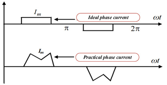
Figure 1.
Waveforms of practical and ideal phase current.
The electromagnetic torque is harmed by the current ripples, which also cause mechanical vibration and auditory noise [8,9,10]. To overcome these limitations, different types of pulse width modulation (PWM) techniques have been proposed which are quite complex and not cost-effective [11]. The conventional PWM scheme is combined with digital PWM methods to limit the speed regulation [12]. However, this technique cannot be used for high-speed applications. A four switch three-phase VSI-based BLDCM drive was proposed to reduce the cost for commercial application [13]. In this topology, one leg consists of two capacitors, which result in uncontrolled flow of current throughout the operation. The grid interleave photovoltaic (PV)-based water pumping system is presented in [14,15]. This scheme mainly focuses on the minimization of current harmonics in the grid. However, the performance of the BLDCM drive is still unaddressed. The chaotic adaptive tuning method was developed to optimize speed control of the motor drive [16]. Therefore, for a wide speed range of BLDCM drives, a field programmable gate array (FPGA)-based digital PWM control technique was developed [17]. In this control scheme, current ripple is partially eliminated. The FPGA technique is cheaper but the closed-loop control is quite complex [18]. Furthermore, a digital PWM scheme was proposed to analyze the stability of the BLDCM drive for electric vehicle applications [19]. The Lyapunov stability method (LSM) and back-EMF zero crossing sensor technique are used to show the stability of the motor drive.
The DC-controlled PWM was applied to investigate the static and dynamic performance of the torque-speed characteristic [20]. However, this method was not considered due to its complexity. Lee Byoung-Kuk et al. implemented a PWM control scheme for low-cost application [21]. In this method, a minimum number of circuit parameters is required and the commutation interval can be estimated by the phase voltage approach. Nevertheless, this method is insensitive to motor parameters. Furthermore, the effect of the NCZ and diode freewheeling interval was not considered throughout the operation. Unipolar and bipolar PWM techniques are reported to reduce the harmonics and switching losses [22]. Unipolar PWM is employed for low-cost applications whereas bipolar PWM can be used for high-cost applications [23]. The current pulsation during the commutation can be reduced with the help of unipolar PWM [24]. Furthermore, a modified bipolar PWM was employed to achieve fast deceleration and acceleration rates during the braking process [23]. S. Mansouri et al. presented a hybrid resonant PWM method to assist classical BLDCM drive for power factor correction (PFC) [25]. In this method, the PWM was only applied in the DC-DC converter kept in front of the VSI unit. Therefore, diode freewheeling and CCR still remained unaddressed throughout the operation. A topology based on a Luo converter placed before the classical BLDCM drive using conventional PWM was developed for the PFC [26]. The major concern with this topology is that the occurrence of current ripples due to the commutation, in addition to diode freewheeling, is not discussed.
The phase lock loop (PLL)-dependent commutation rectification strategy was proposed for a high-speed BLDCM drive [27]. In this process, torque ripple is greatly reduced and the power factor is improved. A PWM system was used in a neutral point clamped (NPC) inverter [28]. In this topology, with the aid of an NPC inverter, a large amount of current ripple is successfully extracted. However, twelve gate pulses and two proportional integral (PI) controllers are separately required for speed, and current control and a dead band circuit are used to complete the closed-loop operation. A large number of switch counts consist of the neutral point clamp (NPC) inverter which increases the overall device expense [29]. Therefore, this technique cannot be used for low-power applications. The ON-PWM technique was introduced to address the current and torque ripples in BLDCM drives [30]. It was observed that the current and torque ripple is alleviated during the commutation period. The ON-PWM technique only prevents diode freewheeling during the starting 30° of electrical cycles of commutation. However, diode freewheeling current remains unaddressed in the inactive phase for a duration of 30° of electrical cycles of commutation at the end. In order to decrease the diode freewheeling at the last 30° of the electrical cycle in the commutation interval, the PWM-ON control technique was suggested [31]. Using this technique, the diode freewheeling during the last 30° of the electrical cycle of the commutation can be efficiently suppressed. Nevertheless, the freewheeling current occurs in the former 30° of the electrical cycle in commutation. The classical BLDCM drive system based on the PWM-MAC method was used to analyze the effect of freewheeling diodes during the NCZ [32]. It should be noted that the torque ripple is efficiently decreased at around 28%. The dq-Transformation is used to partially reduce copper losses and torque pulsations [33,34,35]. Vectorial control greatly enhances motor performance. Therefore, it is not necessary to measure the machine’s dynamic parameters, which are stator resistance, inductance, mutual inductance, and current.
Furthermore, the DC-DC converter-assisted BLDCM drive topology is widely preferred to mitigate the CCR. The DC-DC converter is used to draw regulated DC-link voltage across the VSI unit during the commutation period. To eliminate the current ripple, the three-phase multi-level inverter topology has been utilized [36]. To mitigate the current ripple, a buck converter-based BLDCM drive was reported [37]. In order to address current ripple for high-speed application, a super-lift Luo converter was used before the classical BLDCM drive [38]. A classical SEPIC converter-based BLDCM drive was implemented to suppress the CCR [39]. Two similar classical single-ended primary inductor converters (SEPICs) are placed prior to a three-level VSI with a DC-link voltage (DCLV) network to diminish the CCR [40]. Due to the large switch count, the size, switching losses, and complexity increase and system efficiency decreases. Therefore, a single classical SEPIC converter was used to overcome these limitations [41].
All of the aforementioned DC-DC converter-based topologies have been analyzed to mitigate current/torque ripples in the CZ. In addition, regulated DC-link voltage from the DC-DC converter has only been applied for the CZ. However, information regarding the NCZ and diode freewheeling are not discussed in these topologies. Hence, this paper proposes a PWM-MAC control scheme which is applied for a modified SEPIC (MSEPIC) converter-based BLDCM drive to analyze the effect of the NCZ and freewheeling diodes. The PWM-MAC strategy was designed by taking key merits of both ON-PWM and PWM-ON techniques.
The BLDCM drive still suffers from commutation current ripple (CCR) and diode freewheeling during the non-commutation zone (NCZ), which leads to undesired speed regulation, mechanical vibration, and audible noise. The CCR mainly results from the stator inductance, which causes unequal slew rates for the phase currents at the interim of the CZ. Moreover, undesired current flows through the freewheeling diode of inactive phases, which introduces an additional current ripple in the BLDCM drive. In this study, the PWM-MAC approach was employed to simultaneously minimize the diode freewheeling current during the initial 30° of the electrical cycle and the final 30° of the electrical cycle in the NCZ, enabling the examination of the impact of diode freewheeling during the NCZ. It is known that the torque ripple becomes zero if the applied voltage is nearly equal to four times the back-EMF. Hence, the regulated DC-link voltage is required to reduce the CCR during the CZ [26]. Therefore, the MSEPIC converter can be used to maintain a high DC-link voltage across the VSI unit of the BLDCM drive. Regulated DC-link voltage is delivered to the VSI unit both before and after the commutation intervals via the DCLV selecting circuit. In this process, the rates of incoming and outgoing phase currents are similar, which results in minimum current and torque ripples. During the CZ and NCZ, the suggested system can be used to reduce the CCR and diode freewheeling, respectively. The validity of the proposed control strategy was tested using MATLAB/Simulink and an experimental prototype. The major contributions of this paper are outlined as follows:
- The current study placed a strong emphasis on reducing the current and torque ripples during the CZ. More particularly, many modes of operation for mathematical modeling of torque ripple are provided. In order to determine the duty cycle, commutation time span, and phase current during the turn ON and turn OFF procedures, the impact of PWM on electromagnetic torque was also analyzed.
- The controlled DC-link voltage is provided to the VSI unit using the MSEPIC converter and DCLV circuit. The performance of the BLDCM is enhanced by this setup, which successfully reduces the CCR during the CZ.
- Analysis was conducted on the impact of the freewheeling diode in the NCZ. Additionally, a PWM-MAC control strategy is used to prevent diode freewheeling during the NCZ.
- The PWM-MAC control approach was primarily designed to solve the shortcomings of traditional PWM-ON and ON-PWM topologies. This prevents the negative impact caused by diode freewheeling. The proposed PWM-MAC method has a feature that ensures minimal current and torque ripples.
The paper is divided into six sections. Section 2 discusses the commutation process without the effect of PWM. The torque ripple analysis in PWM mode is presented in Section 3. The analytical method to determine the duty ratio for the DC-DC converter is covered under Section 4. Section 5 discusses the theoretical and experimental findings of the BLDC motor drive. Finally, a concluding remark and future scope are presented in Section 6.
2. Commutation Mechanism without PWM
The three-phase star connected-type stator is mostly preferred in BLDCM drives [4,5,6]. A typical equivalent winding structure of the BLDCM drive is depicted in Figure 2. The rotor is covered by permanent magnets, which provide field flux.
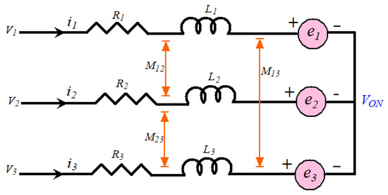
Figure 2.
Equivalent winding structure of the BLDCM.
In this figure, V0N is the voltage between ground and neutral point; V1, V2, and V3 are the phase voltages (i.e., VSI pole voltage); i1, i2, and i3 are the stator phase currents; R1, R2, and R3 are phase winding resistances; e1, e2, and e3 are the back-EMFs; L1, L2, and L3 are the phase winding inductances; and M12, M23, and M13 are mutual inductances.
From Figure 2, the voltage balance equation of the BLDCM drive is derived as:
The electromagnetic torque can be estimated as:
The classical BLDCM drive has six commutation sequences, each having a time span of 60° electrical. Hence, only two legs of the VSI operate at the same time and the remaining leg is inactive. Further, Equation (2) can be expressed as:
where Im = i1 = i2 = i3.
Electromagnetic torque of the BLDCM is estimated from Equation (4):
where Kte = motor torque constant in N-m/Ampere.
It is presumed that the commutation takes place from active phase ‘a’ to inactive phase ‘b’ for the torque ripple examination, whereas phase ‘c’ stays in active mode.
Since the transition takes place for a short period within the flat-top region of the back-EMF, Em is equal to the peak value of the back-EMF. Then, the initial voltage at the beginning of commutation can be calculated as V1 = 0 = V3; V2 = VS; e1 = e2 = Em and e3 = −Em.
From Equation (2), the BLDCM’s torque (before commutation) can be determined as:
From Figure 3, current i1 approaches zero from its peak value Im within a time interval called the fall time (tf), and can be drawn as follows:
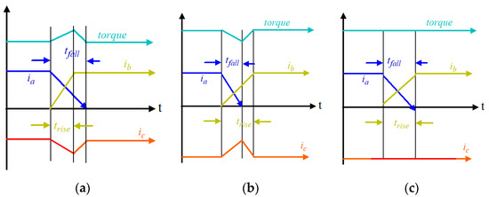
Figure 3.
Characteristic of phase current during the commutation: (a) positive torque ripple (i.e., tfall > trise); (b) negative torque ripple (i.e., tfall < trise); and (c) zero torque ripple (i.e., tfall = trise).
Similarly, current i2 approaches the peak value Im from zero within a time interval known as the rise time (tr), and can be estimated by Equation (7):
From Equation (8), effective phase ‘c’ current can be obtained by:
Using Equations (3) and (8), the electromagnetic torque is drawn as follows:
Finally, the torque ripple is estimated as:
As per Equations (8)–(10), the outcomes are illustrated below:
- If VS > 4Em, then the motor speed is less than the actual value which means that the i2 current reaches a steady-state position before i1 dives to zero, as presented in Figure 3a. Hence, the commutation never finishes at the same time, which causes a positive increment in torque ripple [5].
- If VS < 4Em, then the motor speed is greater than the actual value which means that the i2 current cannot gain a steady-state position when i1 falls to zero, as presented in Figure 3b. Hence, the commutation never occurs at the same time, which causes negative torque ripple.
- If VS = 4Em, then the motor speed is equal to the actual value which means that the i2 current gains a steady-state position when i1 decreases to zero, as presented in Figure 3c. Hence, the commutation finishes at the same time, which causes zero torque ripple [8].
3. Torque Ripple Analysis in PWM Mode
The major conclusions drawn from the previous section are that the current and torque ripple can be significantly decreased by the following methods:
- In the non-commutation span, where the motor speed is lower than the pre-set value, the rate of rise of the growing current at the turn-on process decreased. Using PWM in the outgoing phase switches removes the pulsation of the switch current [15,16,17].
- In the non-commutation process, where the motor speed is greater than the pre-set value, the rate of decline in the diminishing current at the turn-off mechanism decreased. To prevent the pulsation of the current, PWM is used in the incoming phase switches [15,16,17,18].
- Maintain the VS = 4Em to remove the torque ripple with the employment of the DC-DC converter used before the BLDCM drive.
When the pole voltage is above the input voltage or under the null voltage, the CCR arises in the inactive phase during Δt1 and Δt2, as shown in Figure 4. The amplitude of V0N is significantly reduced by adopting different PWM control schemes. λφ is named the electrical voltage level state of motor phase φ (φ = 1, 2, 3); λφ = 1 means that the pole voltage is equal to the applied voltage, indicating that the related power switch or diode in the VSI upper arm is in the ON position.
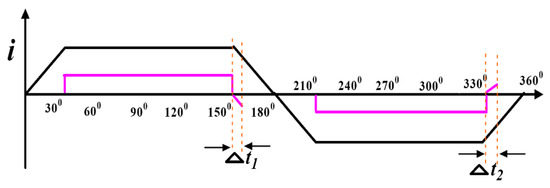
Figure 4.
Freewheeling phase current after the commutation.
Although λφ = 0 means that the pole voltage is zero, the subsequent power switch or diode in the lower arm of the VSI is in the ON state. The phase φ pole voltage equation can now be written as:
In this analysis, it is considered that phase φ1 and phase φ3 are active and phase φ2 is inactive. The following set of equations are derived from Equation (11):
In this situation, iφ1 = iφ3 = Im; eφ1 = −eφ3 = Em. From Equation (12):
In steady-state condition when λφ = 0 and λφ = 1, Equation (12) will be as follows:
Since then, according to Equation (13), back-EMF is represented as:
The pole voltage equation for inactive phase can be determined from Equation (11) with substituting iφ2 = 0, giving:
The following conclusion is deduced from Equation (12):
Ideally, zero current flows in phase φ2 if the pole voltage of the corresponding phase is above the input voltage or below the zero voltage. Nevertheless, the freewheeling diode of the same branch is turned-on and freewheeling current appears in the phase φ2. There is no freewheeling current in the phase φ2 if:
Substituting Equation (16) into Equation (18) we obtain:
From Figure 5, some important discussions are presented as follows:
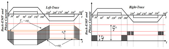
Figure 5.
Waveforms of neutral point potential and back-EMF voltage (red lines indicate different voltage levels).
As per Equation (19), the corresponding value of V0N is presented in the shadow portion of Figure 5. If the rotor angle position is in the range of 0–30° or 150–180°, the amplitude of eφ3 must be positive. Based on Equations (17) and (19), V0N = 0, (if λφ1 = λφ3 = 0) or V0N = VS/2, (if λφ1 = 1, λφ3 = 0 or λφ1 = 0, λφ3 = 1) as per Figure 5 (refer left-trace). The above discussion indicates that the power switch of the negative group of the VSI unit is turned on and the diode in the lower arm remain in the ON state (i.e., freewheeling mode). Hence, the suitable PWM control is implemented in the corresponding upper legs of the VSI and the power switches on the negative group are kept in the ON state continuously.
A similar procedure can be applied if the rotor angle position is in the range of 180–210° or 330–360°. The amplitude of eφ3 must be negative. Based on Equations (17) and (19), V0N = VS, (if λφ1 = λφ3 = 1) or V0N = VS/2, (if λφ1 = 1, λφ3 = 0 or λφ1 = 0, λφ3 = 1) as per Figure 5 (refer right-trace). The above discussion indicates that the power switch of the positive group of the VSI is turned-on and the diode in the upper arm remain in the ON state, i.e., freewheeling mode. Hence, the suitable PWM control is implemented in the corresponding lower legs of the VSI and the power switches on the positive group are kept in the ON state continuously.
3.1. Case–1
As the BLDCM runs at lower speed, PWM is applied to incoming phase ‘b’ while phase ‘a’ is turned-off to slow down the rate of phase ‘b’ current during the commutation in order to suppress the current pulsation. The system mathematical model during the commutation can be represented as follows:
In steady-state, condition Equation (20) can be expressed as:
Non-commutation (phase ‘c’) current is derived from Equation (21):
where δ22 is the gate pulse duty ratio of the turn-on phase at the commutation. From Equations (20) and (21):
Now turn-off phase current can be drawn as:
The approximate time taken to turn-off the phase (i.e., phase ‘a’ current must fall to zero) can be calculated as:
During the commutation process, the magnitude of the non-commutation phase current (phase ‘c’ current) must be constant. This situation can be estimated from Equation (22) as follows:
It is known that 0 ≤ δ22 ≤ 1 during the commutation interval. This situation occurs if
4Em + 3RIm ≤ VS, i.e., the BLDCM operates in the low-speed area. The following results are obtained from Equation (26):
- If , the non-commutation phase current goes down in the CZ as per Equation (22).
- If , the non-commutation phase current goes up in the CZ as per Equation (22).
Equation (26) can be used in Equation (25) to derive the required commutation time span (tcs). The magnitude of the non-commutation current can be maintained constant for a duration of tcs.
3.2. Case–2
If the BLDCM runs at high speed, PWM is implemented on incoming phase ‘a’ while phase ‘b’ is turned OFF to slow down the rate of phase ‘a’ current during the commutation in order to mitigate the current pulsation. The mathematical model of system can be represented as:
In steady-state condition, Equation (28) can be expressed as:
Non-commutation (phase ‘c’) current is derived from Equation (29):
where δ11 is the duty ratio. From Equations (28) and (29):
From Equation (31), i2 can be derived as:
The approximate time is taken to turn ON the phase (i.e., phase ‘a’ current must fall to zero) and ton can be calculated as:
At the CZ, the magnitude of the non-commutation phase current must be constant. This situation can be estimated from Equation (30) as follows:
It is known that 0 ≤ δ11 ≤ 1 during the commutation interval. This situation occurs if
4Em + 3RIm ≤ VS, i.e., the BLDCM operates in the low-speed area. The following results are obtained from Equation (34):
- If , the non-commutation phase current goes down in the CZ as per Equation (30).
- If ,the non-commutation phase current goes up in the CZ as per Equation (30).
Substituting Equation (34) into Equation (33) gives the required commutation time span (tcs). The magnitude of the non-commutation current can be maintained invariably for a duration of tcs:
Similar results can be obtained when the same mathematical analysis is undertaken for the negative groups (lower arms of the VSI).
The PWM-ON control technique can effectively reduce diode freewheeling at the conclusion of the commutation period for a duration of 30° of the electrical cycle. However, at 30° electrical, the diode freewheeling still happens at the start of commutation. Similar to this, the ON-PWM can prevent diode freewheeling for a span of 30° electrical at the start of the commutation interval. However, in the later 30° electrical zones, freewheeling diodes are still present. The simultaneous execution of both tasks is proposed using the PWM-MAC control approach. Therefore, for a length of 30° electrical, the suggested PWM approach can reduce freewheeling diode current in the earlier and later commutation intervals.
4. Estimation of Duty Cycle for the MSEPIC Converter
Figure 6 shows the circuit diagram of the MSEPIC converter while various modes of operations are shown in Figure 7. The converter provides a high DC voltage. Because of the large voltage range, the static gain of the converter enhances the output characteristic [39,41]. In addition, the ripple of the input current is naturally minimized, leading to lower losses. Thus, the performance of the converter increases significantly. The converter can potentially be used to alleviate the BLDCM drive’s CCR.
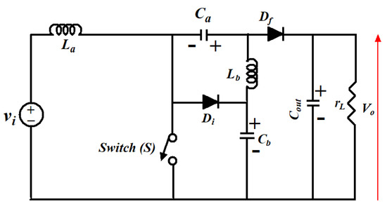
Figure 6.
Circuit layout of MSEPIC converter.
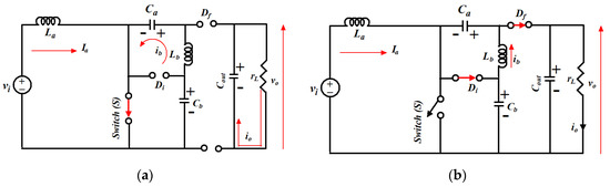
Figure 7.
Switching operations of MSEPIC converter: (a) during DT; (b) during (1-D)T.
The gain for the converter is obtained from Equation (36):
Equation (8) shows that the slew rate of i1 and i2 relies on VS as well as back-EMF during the CZ. The VS is normally irreducible, while Em relies on the speed of the motor. The torque ripple is shown in Equation (10) to be equivalent to the VS−4Em. Therefore, if VS during the commutation is retained closer to 4Em, the torque ripple essentially disappears. In order to achieve controlled DC voltage during the CZ, various DC-DC converter-based topologies have been suggested.
A MSEPIC converter was used in this study to obtain flexible DC-link voltage to establish VS = 4Em for successful torque ripple reduction during the CZ. In Equations (9) and (10), if VS = 4Em, the rising and falling current slew rate is identical (i.e., tf = tr), resulting in zero ripples during the commutation.
MOSFETs are used to design the MSEPIC converter and the DCLV circuits. To obtain the regulated DC-link voltage, the duty cycle of the ‘S’ varies. The inverter input DC-link voltage can be adjusted using switches K1 and K2. Switch K2 is closed during CZ, so the output voltage (Vo) of the MSEPIC converter is chosen as the inverter input. The PWM-ON control technique can effectively reduce diode freewheeling at the end of the commutation interval for a span of 30° electrical. However, the diode freewheeling still occurs in the beginning of commutation for 30° electrical. Similarly, the ON-PWM can suppress the diode freewheeling at the beginning of the commutation interval for a span of 30° electrical.
Using Equation (4), Equation (19) can be rewritten as:
D can be derived from Equation (38) to achieve Vo = 4Em:
To control the DC-link voltage, the duty cycle can be determined using Equation (39). If the speed changes, the duty cycle can alter. During the commutation period, the voltage obtained by conversion according to the duty cycle specified in Equation (39) can be employed. It should be observed that the converter’s voltage exactly matches four times the back-EMF, producing no torque ripple according to Equation (10).
5. Simulation and Experimental Results
It is clear that the current flows in the inactive phase in the two zones of either PWM-ON mode or ON-PWM mode due to the freewheeling diode. The PWM-MAC scheme is proposed to encounter the CCR in the CZ and the freewheeling diode during the NCZ. The phase currents and corresponding back-EMFs are shown in Figure 8. There are four inactive states: 0−π/6 zone, 5π/6−π zone, π−7π/6 zone, and 11π/6−2π zone (refer phase ‘a’ current and back-EMF).
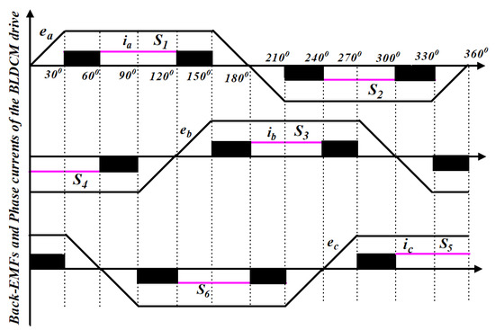
Figure 8.
Performance characteristic of the proposed PWM-MAC control techniques.
Various freewheeling actions are summarized in Table 1. It is noted that the back-EMF (e1) is positive during the 0−π/6 zone and 5π/6−π zone. The switch S4 is continuously turned ON and PWM-ON is applied for switch S5 during the 0−π/6 zone. However, ON-PWM is used in switch S3 and switch S6 is turned ON continuously in 5π/6−π zone. A similar analysis can be carried out in the π−7π/6 and 11π/6−2π zones, in which the value of back-EMF (e1) is negative. The upper group switch S3 is in active mode and PWM-ON is applied in lower group switch S6 during the π−7π/6 zone, whereas ON-PWM is employed for switch S4 and switch S5 is the active switch in the 11π/6−2π zone.

Table 1.
Switching pattern before and after the commutation zone.
After the simulation of PWM-MAC strategy is completed, a hardware setup was established in the laboratory and experimental outcomes were compared with the simulation results. The framework of the proposed PWM scheme is illustrated in Figure 9. Numerous parameters mentioned on the motor nameplate are mentioned in the Appendix A.
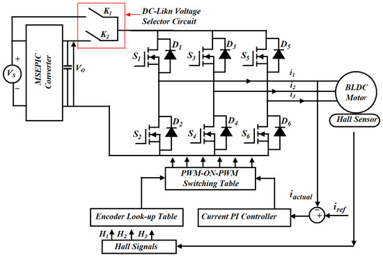
Figure 9.
Framework for MATLAB/Simulink and experimental setup of the proposed control strategy for the BLDCM drive.
In Figure 9, switch K1 is turned ON during the NCZ and the BLDCM is fed from voltage VS. In the CZ, switch K2 is on to provide VS = 4Em and the BLDCM drive is powered from the output voltage of the MSEPIC converter (i.e., VO = 4Em). The simulation phase current waveforms of the classical BLDCM drive and traditional PWM scheme-based drives are presented in Figure 10 and Figure 11. It is observed that the shape of the current is almost similar to that of the conventional BLDCM drive but in the pulse form.
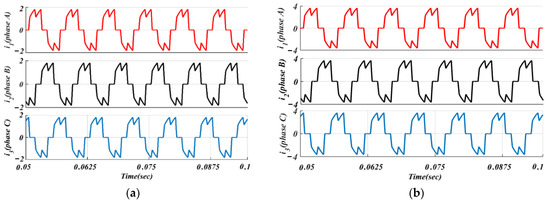
Figure 10.
Simulated phase currents of the classical BLDCM drive: (a) lightly loaded or partially loaded (40% of maximum load); and (b) full load (85% of maximum load).
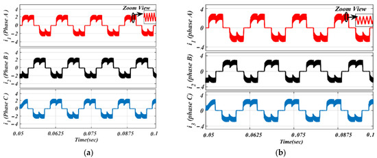
Figure 11.
Simulated waveforms of the phase current based on traditional PWM scheme: (a) lightly loaded or partially loaded (40% of maximum load); and (b) full load (85% of maximum load).
Moreover, using the same parameters, phase current results of the BLDC motor based on the traditional ON-PWM technique and MSEPIC converter placed before the VSI unit are depicted in Figure 12. The same circuit topology was then tested on the PWM-ON control scheme and its current outcomes are presented in Figure 13 for the same loading effects.
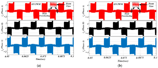
Figure 12.
Simulated waveforms of the phase current based on ON-PWM scheme: (a) lightly loaded or partially loaded (40% of maximum load); and (b) full load (85% of maximum load).
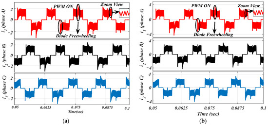
Figure 13.
Simulated waveforms of the phase current based on PWM-ON scheme: (a) lightly loaded or partially loaded (40% of maximum load); and (b) full load (85% of maximum load).
The ON-PWM technique can be applied at the starting 30°. Hence, it can suppress the freewheeling diode in the starting of commutation for a 30° span but, for the last 30° of the commutation interval, the issue of the freewheeling diode remains unaddressed. To alleviate this issue, the PWM-ON technique is employed, which can suppress the freewheeling diode at the beginning of commutation for a duration of 30°. Its simulation results are shown in Figure 13 under the same environment.
It is worth noting from Figure 13 that the freewheeling diode comes into the picture at the initial 30° of commutation. Due to the diode freewheeling in both ON-PWM and PWM-ON techniques, the current ripple is still superimposed with the phase current in the NCZ. Therefore, a novel hybrid PWM technique was developed which is a combination of both ON-PWM and PWM-ON techniques, and named the PWM-MAC technique. Based on the proposed PWM technique, the stator current waveforms are illustrated in Figure 14 at the same load. From Figure 14, it is seen that the proposed PWM-MAC control scheme can eliminate the freewheeling diode in both the initial and final 30° of the commutation. Hence, the freewheeling diode action is completely eliminated and ripple-free stator current is obtained. The above results were analyzed at the switching frequency of 20 kHz.
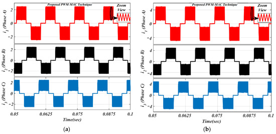
Figure 14.
Simulated waveforms of the phase current based on proposed PWM scheme: (a) lightly loaded or partially loaded (40% of maximum load); and (b) full load (85% of maximum load).
To validate the simulation results, an experimental prototype of the BLDCM drive based on an MSEPIC converter using the PWM-MAC method was developed and tested under lightly loaded and fully loaded conditions. The experimental setup for the proposed PWM control strategy-based BLDCM drive is presented in Figure 15.
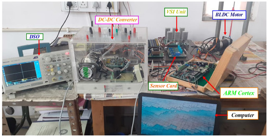
Figure 15.
Experimental setup for BLDCM drive using an MSEPIC converter based on PWM-MAC.
The gate signal given to the switch ‘S’ of the converter is depicted in Figure 16a. Additionally, the applied DC-link voltage across the VSI unit before commutation is illustrated in Figure 16b. Figure 16c clearly shows that the DC-link voltage is equal to four times the back-EMF during the commutation interval. The classical BLDCM drive was tested on traditional PWM technique at the switching frequency of 20 kHz and its current waveforms are shown in Figure 17.
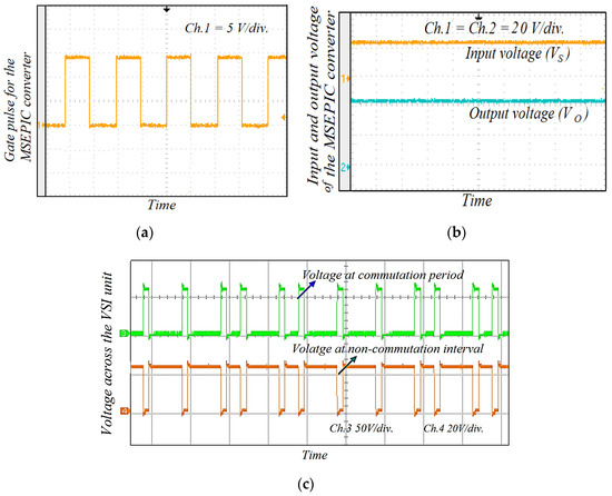
Figure 16.
(a) Gate pulse of the switch ‘S’ in the MSEPIC converter; (b) input and output voltage across the MSEPIC converter; and (c) input voltage applied across the VSI of the proposed control strategy.
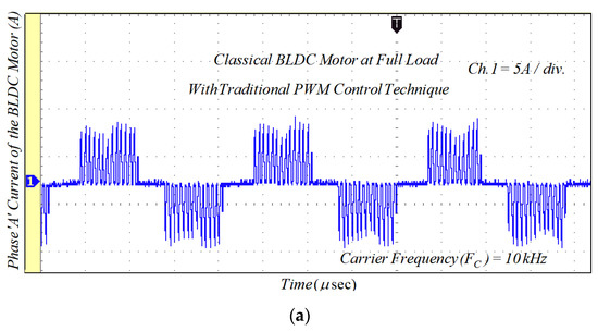
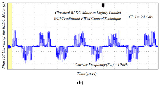
Figure 17.
Experimental results of the phase current for classical BLDCM drive with traditional PWM technique: (a) lightly loaded condition, 2 A/div.; and (b) full load, 5 A/div.
Due to the phase winding inductances and freewheeling diode in the NCZ and CZ, the rectangular-shaped phase current cannot be obtained. Therefore, the MSEPIC converter is used to encounter the CCR in the CZ and the freewheeling diode is eliminated using the ON-PWM, PWM-ON, and PWM-MAC control scheme. Furthermore, the MSEPIC converter applied before the traditional BLDCM drive was tested on the ON-PWM control and its experimental result is depicted in Figure 18. The experimental results of the BLDCM drive for the PWM-ON technique are shown in Figure 19. It is noted from Figure 18 and Figure 19 that the freewheeling diode during the initial 30° and the final 30° has appeared. Therefore, the PWM-MAC technique is employed to mitigate the effect of freewheeling current. The experimental results for the proposed controller are illustrated in Figure 20. From Figure 14 and Figure 20, it can be clearly observed that the software and hardware results match each other. Furthermore, both results show rectangular waveforms, consistent with the major objective of the paper of producing smooth torque. The performance of the proposed system was also tested under various dynamic cases such as a sudden change in loading and modulation index (MI).
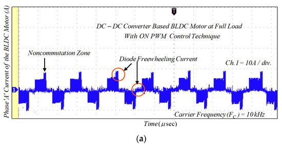
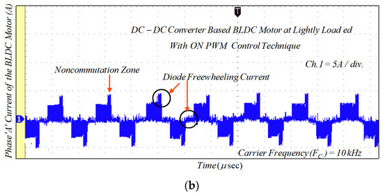
Figure 18.
Experimental results of motor current with ON-PWM technique: (a) lightly loaded condition, 2 A/div.; and (b) full load, 5 A/div.
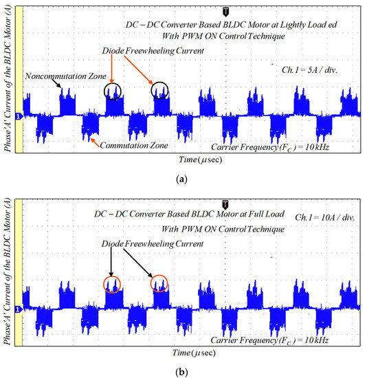
Figure 19.
Experimental results of motor current with PWM-ON technique: (a) lightly loaded condition, 2 A/div.; and (b) full load, 5 A/div.
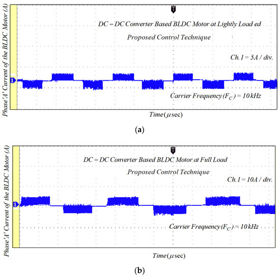
Figure 20.
Experimental results of motor current with PWM-MAC technique: (a) lightly loaded condition, 2 A/div.; and (b) full load, 5 A/div.
Figure 21 illustrates the experimental results of the phase voltage and current through the BLDCM drive when modulation MI is suddenly changed. If MI decreases, then the pole voltage of the VSI unit decreases and the corresponding phase current also goes down. Similarly, the voltage and current increase when MI is increased. The experimental waveform of the motor phase current and MSEPIC converter current during the load change is presented in Figure 22. The motor draws more current when the load is increased, whereas the phase current decreases if load decreases. Finally, a comparative study is presented in Figure 23, which indicates with the validity and effectiveness of the proposed control technique.
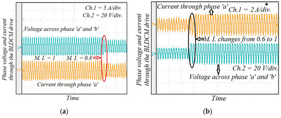
Figure 21.
Experimental results of phase current and output voltage across the VSI unit during the dynamic conditions: (a) MI changes from 1.0 to 0.8; and (b) MI increases from 0.6 to 1.0.
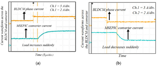
Figure 22.
Experimental results of motor phase current and MSEPIC converter current during the dynamic conditions: (a) load increases; and (b) load decreases suddenly.
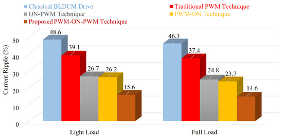
Figure 23.
Comparative study of different techniques with proposed method.
It should be mentioned that the simulated results and the experimental results match. Unlike the PWM-ON technique, which mitigates the freewheeling diode effect during the final 30°, ON-PWM can only lessen the freewheeling diode effect during the first 30°. The proposed PWM-MAC control method, however, can remove the freewheeling diode at the initial and final 30°.
Table 2 provides a comparison of the major existing ripple reduction strategies for BLDCM drives. A key conclusion from Table 2 is that the PWM-MAC scheme is essential for resolving the current ripple that results from a freewheeling diode during the NCZ.
Table 2.
Comparative analysis of the BLDCM drives.
6. Conclusions
In this study, the effect of freewheeling diodes during the non-commutation zone due to traditional PWM was investigated. Additionally, the current/torque ripples were theoretically estimated in the commutation interval. A novel PWM-MAC scheme was proposed to alleviate the diode freewheeling. An MSEPIC converter was utilized to draw the regulated DC-link supply to suppress the CCR. The converter provides a high voltage in a low duty cycle and minimum losses. A comparative study is presented. It is observed that the classical BLDCM offers approximately 46.3% of the current ripples and 41.1% of the corresponding torque ripples, whereas the proposed method provides approximately 14.6% of the current ripples and 8.6% of the corresponding torque ripples. The PWM-MAC method is able to reduce the current ripples by 31.7% and the torque ripples by 32.5%. The effectiveness of the proposed techniques was verified by simulation and hardware results. The simulation and experimental waveforms based on classical PWM and proposed PWM-MAC are presented in different modes. The suggested control technique can be further used in the solar photovoltaic-based BLDCM drive for water pumping systems. The proposed control technique can be used in different industrial and household applications, such as refrigerators, air conditioners, textiles, aviation, medical devices, electric vehicles, solar energy, fuel cells, and modern industrial applications based on renewable energy sources where current ripple or torque ripple mitigation is of great importance.
Author Contributions
Conceptualization, D.K.; methodology, D.K.; validation, D.K. and S.D.C.; formal analysis, D.K.; investigation, D.K., S.D.C.; resources, S.D.C. and M.T.; data curation, D.K.; writing—original draft preparation, D.K.; writing—review and editing, S.D.C., M.T, M.S.H.L. and A.A.; project administration, A.A.; funding acquisition, A.A. All authors have read and agreed to the published version of the manuscript.
Funding
This work is supported by Universiti Kebangsaan Malaysia under Grant Number DIP 2021-003.
Data Availability Statement
Raw data is available from corresponding authors upon reasonable request. Derived data is available within the manuscript.
Conflicts of Interest
The authors declare no conflict of interest.
Appendix A
Three-phase star connected BLDC motor type, rated power = 325 W, number of poles = 4, rated torque = 0.5 Nm, R = 0.28 Ω per phase, L = 0.21 mH per phase, rated speed = 4500 rpm, rated current = 4.5 A, input voltage = 36 V, PWM carrier frequency = 20 kHz and torque constant = 0.11 Nm/A-peak.
References
- Mishra, P.; Banerjee, A.; Ghosh, M. FPGA-Based Real-Time Implementation of Quadral-Duty Digital-PWM-Controlled Permanent Magnet BLDC Drive. IEEE/ASME Trans. Mechatron. 2020, 25, 1456–1467. [Google Scholar] [CrossRef]
- Krznar, M.; Pavković, D.; Cipek, M.; Benić, J. Modeling, Controller Design and Simulation Groundwork on Multirotor Unmanned Aerial Vehicle Hybrid Power Unit. Energies 2021, 14, 7125. [Google Scholar] [CrossRef]
- Abd. Ali, J.; Hannan, M.A.; Mohamed, A.; Pin Jern, K.; Abdolrasol, M.G. Implementation of DSP-Based Optimal Fuzzy Logic Speed Controller for IM Drive Using Quantum Lightning Search Algorithm. Measurement 2020, 153, 107372. [Google Scholar] [CrossRef]
- Milivojevic, N.; Krishnamurthy, M.; Gurkaynak, Y.; Sathyan, A.; Lee, Y.J.; Emadi, A. Stability Analysis of FPGA-Based Control of Brushless DC Motors and Generators Using Digital PWM Technique. IEEE Trans. Ind. Electron. 2012, 59, 343–351. [Google Scholar] [CrossRef]
- Xia, K.; Ye, Y.; Ni, J.; Wang, Y.; Xu, P. Model Predictive Control Method of Torque Ripple Reduction for BLDC Motor. IEEE Trans. Magn. 2020, 56, 1–6. [Google Scholar] [CrossRef]
- Ali, J.A.; Hannan, M.A.; Mohamed, A.; Abdolrasol, M.G.M. Fuzzy Logic Speed Controller Optimization Approach for Induction Motor Drive Using Backtracking Search Algorithm. Measurement 2016, 78, 49–62. [Google Scholar] [CrossRef]
- Glowacz, A. Thermographic Fault Diagnosis of Ventilation in BLDC Motors. Sensors 2021, 21, 7245. [Google Scholar] [CrossRef] [PubMed]
- Park, Y.W.; Ko, J.S.; Kim, D.K. Optimal Design of Step-Sloping Notches for Cogging Torque Minimization of Single-Phase BLDC Motors. Energies 2021, 14, 7104. [Google Scholar] [CrossRef]
- Maroti, P.K.; Padmanaban, S.; Holm-Nielsen, J.B.; Sagar Bhaskar, M.; Meraj, M.; Iqbal, A. A New Structure of High Voltage Gain SEPIC Converter for Renewable Energy Applications. IEEE Access 2019, 7, 89857–89868. [Google Scholar] [CrossRef]
- Shawky, A.; Takeshita, T.; Sayed, M.A.; Aly, M.; Ahmed, E.M. Improved Controller and Design Method for Grid-Connected Three-Phase Differential SEPIC Inverter. IEEE Access 2021, 9, 58689–58705. [Google Scholar] [CrossRef]
- Ali, J.A.; Hannan, M.A.; Mohamed, A. A Novel Quantum-Behaved Lightning Search Algorithm Approach to Improve the Fuzzy Logic Speed Controller for an Induction Motor Drive. Energies 2015, 8, 13112–13136. [Google Scholar] [CrossRef]
- Hannan, M.A.; Ali, J.A.; Mohamed, A.; Uddin, M.N. A Random Forest Regression Based Space Vector PWM Inverter Controller for the Induction Motor Drive. IEEE Trans. Ind. Electron. 2017, 64, 2689–2699. [Google Scholar] [CrossRef]
- Lee, B.K.; Kim, T.H.; Ehsani, M. On the Feasibility of Four-Switch Three-Phase BLDC Motor Drives for Low Cost Commercial Applications: Topology and Control. IEEE Trans. Power Electron. 2003, 18, 164–172. [Google Scholar] [CrossRef]
- Oliver, J.S.; David, P.W.; Balachandran, P.K.; Mihet-Popa, L. Analysis of Grid-Interactive PV-Fed BLDC Pump Using Optimized MPPT in DC–DC Converters. Sustainability 2022, 14, 7205. [Google Scholar] [CrossRef]
- Ammar, A.; Hamraoui, K.; Belguellaoui, M.; Kheldoun, A. Performance Enhancement of Photovoltaic Water Pumping System Based on BLDC Motor under Partial Shading Condition. Eng. Proc. 2022, 14, 22. [Google Scholar] [CrossRef]
- Rodríguez-Molina, A.; Villarreal-Cervantes, M.G.; Serrano-Pérez, O.; Solís-Romero, J.; Silva-Ortigoza, R. Optimal Tuning of the Speed Control for Brushless DC Motor Based on Chaotic Online Differential Evolution. Mathematics 2022, 10, 1977. [Google Scholar] [CrossRef]
- Lin, Y.K.; Lai, Y.S. Pulse-Width Modulation Technique for BLDCM Drives to Reduce Commutation Torque Ripple without Calculation of Commutation Time. In Proceedings of the 2010 IEEE Energy Conversion Congress and Exposition, Atlanta, GA, USA, 12–16 September 2010; pp. 4398–4404. [Google Scholar]
- Hannan, M.A.; Ali, J.A.; Hossain Lipu, M.S.; Mohamed, A.; Ker, P.J.; Indra Mahlia, T.M.; Mansor, M.; Hussain, A.; Muttaqi, K.M.; Dong, Z.Y. Role of Optimization Algorithms Based Fuzzy Controller in Achieving Induction Motor Performance Enhancement. Nat. Commun. 2020, 11, 3792. [Google Scholar] [CrossRef] [PubMed]
- Zhang, Z.; Lin, J.; Zhou, Y.; Ren, X. Analysis and Decoupling Design of a 30 MHz Resonant SEPIC Converter. IEEE Trans. Power Electron. 2016, 31, 4536–4548. [Google Scholar] [CrossRef]
- Kim, D.K.; Lee, K.W.; Kwon, B. Il Commutation Torque Ripple Reduction in a Position Sensorless Brushless Dc Motor Drive. IEEE Trans. Power Electron. 2006, 21, 1762–1768. [Google Scholar] [CrossRef]
- Park, Y.; Kim, H.; Jang, H.; Ham, S.H.; Lee, J.; Jung, D.H. Efficiency Improvement of Permanent Magnet BLDC with Halbach Magnet Array for Drone. IEEE Trans. Appl. Supercond. 2020, 30, 1–5. [Google Scholar] [CrossRef]
- Huang, C.L.; Wu, C.J.; Yang, S.C. Full-Region Sensorless BLDC Drive for Permanent Magnet Motor Using Pulse Amplitude Modulation with DC Current Sensing. IEEE Trans. Ind. Electron. 2021, 68, 11234–11244. [Google Scholar] [CrossRef]
- Kim, H.W.; Shin, H.K.; Mok, H.S.; Lee, Y.K.; Cho, K.Y. Novel PWM Method with Low Ripple Current for Position Control Applications of BLDC Motors. J. Power Electron. 2011, 11, 726–733. [Google Scholar] [CrossRef]
- Valle, R.L.; de Almeida, P.M.; Ferreira, A.A.; Barbosa, P.G. Unipolar PWM Predictive Current-Mode Control of a Variable-Speed Low Inductance BLDC Motor Drive. IET Electr. Power Appl. 2017, 11, 688–696. [Google Scholar] [CrossRef]
- Bist, V.; Singh, B. An Adjustable-Speed PFC Bridgeless Buck-Boost Converter-Fed BLDC Motor Drive. IEEE Trans. Ind. Electron. 2014, 61, 2665–2677. [Google Scholar] [CrossRef]
- Shchur, I.; Lis, M.; Biletskyi, Y. Passivity-Based Control of Water Pumping System Using Bldc Motor Drive Fed by Solar Pv Array with Battery Storage System. Energies 2021, 14, 8184. [Google Scholar] [CrossRef]
- Xie, S.; Wang, X.; Qu, C.; Wang, X.; Guo, J. Impacts of Different Wind Speed Simulation Methods on Conditional Reliability Indices. Int. Trans. Electr. Energy Syst. 2013, 20, 1–6. [Google Scholar] [CrossRef]
- Pullaguram, D.; Mishra, S.; Banerjee, S. Standalone BLDC Based Solar Air Cooler with MPPT Tracking for Improved Efficiency. In Proceedings of the 2016 IEEE 7th Power India International Conference, Bikaner, India, 25–27 November 2017; pp. 1–9. [Google Scholar] [CrossRef]
- Leitner, S.; Gruebler, H.; Muetze, A. Cogging Torque Minimization and Performance of the Sub-Fractional HP BLDC Claw-Pole Motor. IEEE Trans. Ind. Appl. 2019, 55, 4653–4664. [Google Scholar] [CrossRef]
- Gu, C.; Wang, X.; Shi, X.; Deng, Z. A PLL-Based Novel Commutation Correction Strategy for a High-Speed Brushless DC Motor Sensorless Drive System. IEEE Trans. Ind. Electron. 2018, 65, 3752–3762. [Google Scholar] [CrossRef]
- Shchur, I.; Jancarczyk, D. Electromagnetic Torque Ripple in Multiple Three-Phase Brushless Dc Motors for Electric Vehicles. Electronics 2021, 10, 3097. [Google Scholar] [CrossRef]
- De, S.; Rajne, M.; Poosapati, S.; Patel, C.; Gopakumar, K. Low-Inductance Axial Flux BLDC Motor Drive for More Electric Aircraft. IET Power Electron. 2012, 5, 124–133. [Google Scholar] [CrossRef]
- Khazaee, A.; Zarchi, H.A.; Markadeh, G.A.; Mosaddegh Hesar, H. MTPA Strategy for Direct Torque Control of Brushless DC Motor Drive. IEEE Trans. Ind. Electron. 2021, 68, 6692–6700. [Google Scholar] [CrossRef]
- Azab, M. Comparative Study of BLDC Motor Drives with Different Approaches: FCS-Model Predictive Control and Hysteresis Current Control. World Electr. Veh. J. 2022, 13, 112. [Google Scholar] [CrossRef]
- Khazaee, A.; Zarchi, H.A.; Markadeh, G.R.A. Real-Time Maximum Torque per Ampere Control of Brushless DC Motor Drive with Minimum Torque Ripple. IEEE Trans. Power Electron. 2020, 35, 1194–1199. [Google Scholar] [CrossRef]
- Wei, J.; Liu, P.; Tao, W. An Incorporated Control Strategy of Commutation and Conduction Torque Ripples Mitigation for BLDCM Drives in Household Appliances. IEEE Access 2019, 7, 108137–108151. [Google Scholar] [CrossRef]
- De Castro, A.G.; De Andrade Pereira, W.C.; De Oliveira, C.M.R.; De Almeida, T.E.P.; Guazzelli, P.R.U.; De Almeida Monteiro, J.R.B.; De Oliveira, A.A. Finite Control-Set Predictive Power Control of BLDC Drive for Torque Ripple Reduction. IEEE Lat. Am. Trans. 2018, 16, 1128–1135. [Google Scholar] [CrossRef]
- Viswanathan, V.; Jeevananthan, S. Approach for Torque Ripple Reduction for Brushless DC Motor Based on Three-Level Neutral-Point-Clamped Inverter with DC-DC Converter. IET Power Electron. 2015, 8, 47–55. [Google Scholar] [CrossRef]
- Viswanathan, V.; Seenithangom, J. Commutation Torque Ripple Reduction in the BLDC Motor Using Modified SEPIC and Three-Level NPC Inverter. IEEE Trans. Power Electron. 2018, 33, 535–546. [Google Scholar] [CrossRef]
- Kumar, D.; Gupta, R.A.; Tiwari, H. Front-End Zeta Converter Based BLDCM Drive for Efficient Reduction of Commutation Current Ripple Using Notch-Filter. Int. Trans. Electr. Energy Syst. 2020, 30, 1–21. [Google Scholar] [CrossRef]
- Kumar, D.; Gupta, R.A.; Tiwari, H. A Novel High Voltage Gain SEPIC Converter Based on Hybrid Split-Inductor for Renewable Application. IETE J. Res. 2020, 30, 1–17. [Google Scholar] [CrossRef]


Publisher’s Note: MDPI stays neutral with regard to jurisdictional claims in published maps and institutional affiliations. |
© 2022 by the authors. Licensee MDPI, Basel, Switzerland. This article is an open access article distributed under the terms and conditions of the Creative Commons Attribution (CC BY) license (https://creativecommons.org/licenses/by/4.0/).