Article

Calculation Method for Assessing the Storage Capacity of Nitrogen Compounds in LNT Reactors

Department of Combustion Engines, Institute of Vehicles and Duty Machines, Faculty of Automotive and Construction Machinery Engineering, Warsaw University of Technology, Narbutta 84, 02-524 Warsaw, Poland
*
Author to whom correspondence should be addressed.
Died on 11 April 2020.
Energies 2022, 15(20), 7819; https://doi.org/10.3390/en15207819
Submission received: 25 September 2022 / Revised: 13 October 2022 / Accepted: 20 October 2022 / Published: 21 October 2022

Abstract

:
The presented study describes proprietary calculation methods that simulate the process of storing nitrogen dioxide elevation in a catalytic LNT reactor. The first section’s points of reference are the achievements of the article’s authors and the possibility of modeling NO2 adsorption processes in LNT reactors. The rest of the article presents model calculations (proposed by the authors) of the course of the NO2 storage process in LNT reactors. It considers one in its transition period, affecting the improvement and duration of the adsorption process. The conclusion presents selected results of simulation calculations obtained with the help of the equations’ authors and an evaluation of the results. A review of theoretical considerations is consistent with the experimental data, suggesting that the proposed computational solution may be used in future analytical validity assessments of LNT reactor tools under operating conditions.

1. Introduction

Nowadays, the reduction of toxic emissions in vehicles equipped with internal combustion engines a critical problem. Particularly crucial is removing nitrogen oxide emissions [1,2,3]. This is a problem because, simultaneously, there is a tendency to significantly reduce fuel consumption in spark-ignition engines [4]. One solution enabling the supply of spark-ignition engines with lean mixtures is direct fuel injection into the combustion chamber. For several years, engines of this type have been produced and installed in vehicles (particularly passenger cars). Using spark-ignition engines which burn lean mixtures [5] has consequently necessitated the development of new catalytic reactors that reduce the concentration of nitrogen oxides in the exhaust gas when the engine is fed with a lean mixture. Under these conditions, due to the high oxygen content in the exhaust gas, a three-way catalyst (TWC) reactor cannot effectively reduce nitrogen oxides [6]. One solution is using nitrogen oxide trap reactors, often called LNT (Lean NOX Trap) reactors. LNT reactors store nitrogen oxides when the engine is fed with a lean mixture (storage period), whereas when the engine is running on a rich blend (short reduction period) accumulated in the NOX reactor, they are released and reduced [7,8,9]. In this way, cyclic changes in the combustible mixture from rich to lean effectively mitigate the NOX concentration of engines equipped with this type of reactor [9,10].
The NOX storage phenomenon in LNT reactors is one of the layers of active connections capable of storing NO2 on its surface [10]. It is assumed that nitric oxide is oxidized to NO2 after the catalyst in LNT reactors, so this toxic compound represents the total level of nitrogen concentration in the reactor. Figure 1 presents the NO2 storage process in an example reactor with a barium oxide layer base.
The process of storing nitrogen oxides in a reactor occurs in two stages. First, nitrogen oxides are oxidized via platinum to NO2 as per the following reaction [10]:
2 NO + O 2 2 NO 2
In the second stage, nitrogen dioxide reacts with barium oxide, as a result of which thermally stable barium nitrate (Ba(NO3)2) is obtained, as follows [10]:
2 NO 2 + 1 2 O 2 + MO M ( NO 3 ) 2
where M represents elements of an alkali metal group.
Research on the phenomena of nitrogen oxide storage has shown that alkali metal oxides are the best compounds to use as storage media in catalytic reactors. Figure 2 presents changes in NOX adsorption efficiency on selected alkali metals depending on the temperature of the catalytic process [11,12].
Analyzing the data shown in Figure 2, it can be observed that all alkali metals show an increase in the efficiency of nitrogen oxide adsorption with a rise in the temperature of the catalytic process to a specific maximum temperature. Each compound’s adsorption efficiency gradually decreases after exceeding its maximum NOX adsorption temperature. Moreover, it can be observed that different alkali metals obtain different maximum values of nitrogen oxides adsorption at different catalytic conversion temperatures. These properties of nitrogen oxide storage media allow new LNT reactors to achieve highly efficient NOX conversion at selected reactor operating temperatures.

2. Mathematical Model of the NO2 Storage Process

Before developing a mathematical model of the nitrogen oxides storage process in an LNT reactor, the following assumptions were made:
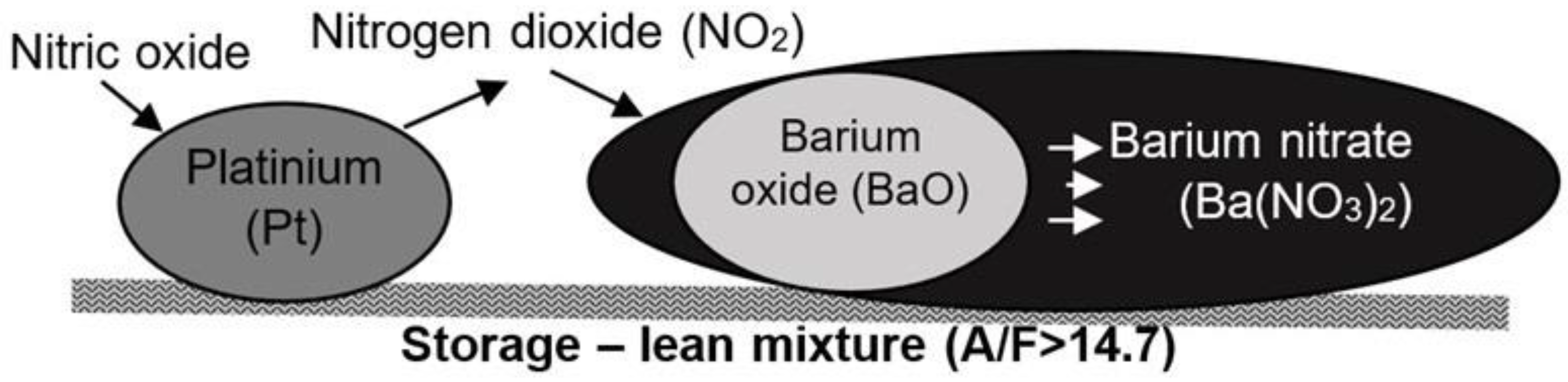
  • Nitrogen oxides will be stored only on the surface of the storage substrate, and will not penetrate the internal structure of this substrate. It was assumed that nitrogen compounds would be stored only on the surface of the storage medium in the adsorption process, and that there would be no process of penetration into the internal structure of this medium as an absorbed compound.
  • The storage process will depend only on the temperature of the catalytic process, the concentration of the stored compound, and the availability of the storage medium for newly inflowing nitrogen oxides.
  • When the storage process begins, the entire storage area will be available for newly inflowing nitrogen oxides.
  • For the developed model to be fully functional, it must allow modification of all parameters responsible for the storage of nitrogen oxides.
  • Only the adsorption of nitrogen dioxide on the storage medium in the form of barium carbonate (BaCO3) according to the following reaction will be responsible for the storage process:
BaCO 3 + 2 NO 2 + 1 2 O 2 Ba ( NO 3 ) 2 + CO 2
Barium carbonate was chosen as the storage medium because barium compounds are used as the NO2 storage compound in most real LNT reactors, [10,12].
For Equation (3), the rate of nitrogen dioxide storage reaction on barium carbonate, according to the general notation of the rate of chemical reactions, was represented by the following equation:
r = k · ( s NO 2 ) 2
where k represents the reaction constant (1 /s) and sNO2 represents the mass concentration of nitrogen dioxide at the reactor inlet (g /m3).
It is known that in the reactors of nitrogen oxide traps, as the duration of the storage process decreases, the amount of storage space capable of binding the newly incoming nitrogen oxides decreases. Therefore, the rate of storage reaction decreases as the reactor storage capacity decreases. For this reason, an additional parameter was introduced into Equation (4) called the reactor storage capacity loss factor Ψ. This parameter varies from 0 for a storage surface fully available for incoming nitrogen oxides to a value of 1 for the case where the storage surface is completely bound in the form of nitrates and is unable to store any more nitrogen oxides. With this assumption, Equation (4) took the following form:
r = k · ( s NO 2 ) 2 · ( 1 Ψ )
As mentioned above, the NO2 storage reaction rate depends on the degree of filling of the reactor with nitrogen oxides previously bound in it, which increases with the duration of this process. This rate is, therefore, dependent on the instantaneous state of the reactor’s storage surface. In this case, the general formula of the presented reaction mechanism describing the state of the storage surface of an LNT reactor was defined as follows:
Ψ i t i · ( σ · P mag ) = r i           for   i = 1 t max
Ψ t · ( σ · P mag ) = K m · s NO 2 · ( 1 Ψ )
where Km represents the storage reaction constant (1/s), Pmag represents the coefficient describing the amount of the total surface of channels available in the reactor per its volume (m2/m3), σ represents the coefficient describing the maximum possible degree of coverage of the reactor surface with nitrogen oxides (g/m2), and (σ∙Pmag) represents the total NO2 storage capacity in the reactor (g/m3).
After ordering and solving Equation (7), the final formula was obtained, which shows the dependence of the change in the coefficient of the loss of the reactor storage capacity on the duration of the storage process, the total storage capacity of the reactor, and the concentration of nitrogen oxides supplied to its inlet:
Ψ = e ( K m · s NO 2 · t P mag · σ ) + 1
In Equation (8), the t-factor represents the duration of the storage process in seconds. During the process, the remaining parameters influencing the value of coefficient Ψ are constant; therefore, in the above equation, the coefficient value for the loss of reactor storage capacity is only a function of time.
In the developed model, which describes the momentary state of filling the reactor’s storage surface with nitrogen oxides, there is no link between the NOX storage process and the temperature at which this process occurs. As shown in Figure 2, the temperature of the catalytic process affects the course of the efficiency of nitrogen oxides adsorption on the storage medium. To consider a reactor’s operating temperature in the model calculations, the Km parameter (storage reaction constant) was modelled based on the Arrhenius equation [13], which describes the dependence of the chemical reaction rate on the temperature of its occurrence. As a result, the constant reaction Km takes the following form:
K m = | k 1 · e ( T 1 T R )   k 2 · e ( T 2 T R ) | +   w k
where k1 and k2 represent calibration coefficients (1/s), T1, and T2 represent activation and deactivation temperatures for the storage of nitrogen oxides (K), respectively, TR represents the reactor’s operating temperature (K), and wk is a correction factor.
The coefficient wk allows the introduction of a correction related to the external conditions of the reactor’s operation. It is determined experimentally for each specific reactor model. It assumes the value of 0 for normal conditions.
The values of the k1 and k2 constants were determined experimentally by comparing computational data regarding the concentration of nitrogen oxides downstream of the reactor with experimental data.
The mathematical model of the loss of storage capacity presented in this paper is the authors’ model; it may, at a later stage (after its calibration and verification based on empirical research), be used to calculate instantaneous values of the concentration of nitrogen oxides at a reactor outlet. It is based on generally accepted mathematical and physical dependencies, particularly the Arrhenius equation. Still, the solution proposed by the authors of this paper allows us to relate most of the factors influencing the course of the NO2 storage process in an LNT reactor using simple mathematical equations. Using these mathematical equations, simulation calculations of the NO2 storage process can be carried out for selected temperatures of the catalytic process, nitrogen oxide concentrations at a reactor’s inlet, and various total NO2 storage capacities. Additionally, the change in a reactor’s storage efficiency as a function of its operating temperature can be shaped by modifying the Km coefficient. To date, there are no similar solutions in scientific studies that use several mathematical equations to calculate the NO2 storage capacity of an LNT reactor while taking into account so many influencing factors.

3. Simulation Calculations of the Nitrogen Oxide Storage Process

To perform simulation calculations of the NO2 storage process in the reactor it was necessary to determine the activation and deactivation temperatures of the NO2 storage process (T1 and T2, respectively). As previously mentioned, in LNT reactors NO2, the stored compound, is formed due to NO oxidation via a catalyst (one of the reactor’s active layers). Research has shown that the oxidation process of NO to NO2 via platinum begins at temperatures of approximately 200 °C [14], which in the case of simulation calculations corresponds to the temperature of T1. NO2 formation in a reactor disappears at approximately 350 °C, corresponding to temperature T2 [15]. The second important parameter necessary to perform the calculations was the total storage capacity of a reactor (σ·Pmag), which was determined based on estimates of the theoretical maximum storage capacity of an LNT reactor and the results of physicochemical studies of the active surface of an actual reactor. These calculations indicated that a reactor with a 1 dm3 volume contains 30 g/dm3 of storage compounds, which could possibly accumulate approximately 0.38 g/dm3 of NO2. However, a reactor containing 15 g/dm3 of storage compound can accumulate approximately 0.19 g/dm3 of NO2 [16].
Taking into account the calculations presented earlier, simulations were carried out for two reactor storage volumes and two NO2 concentrations at their inlet, according to the following values:
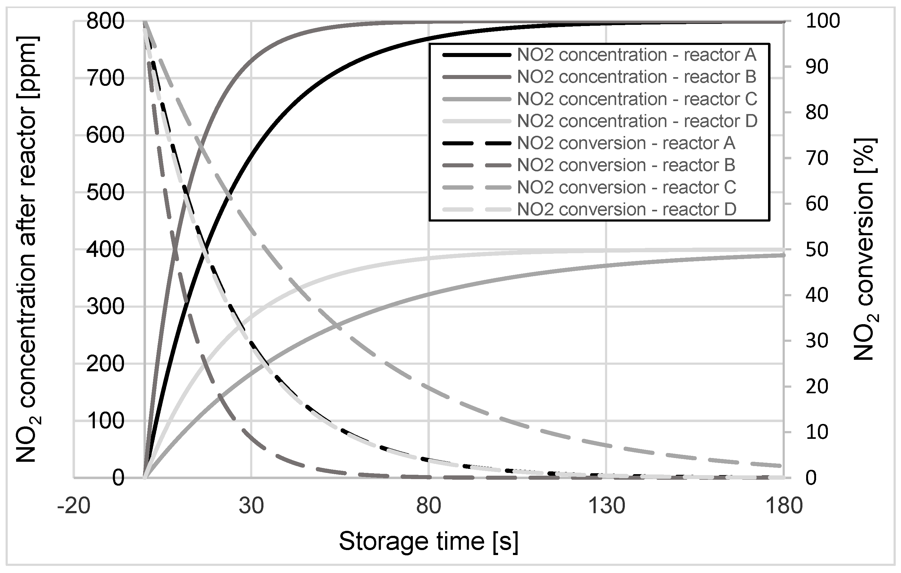
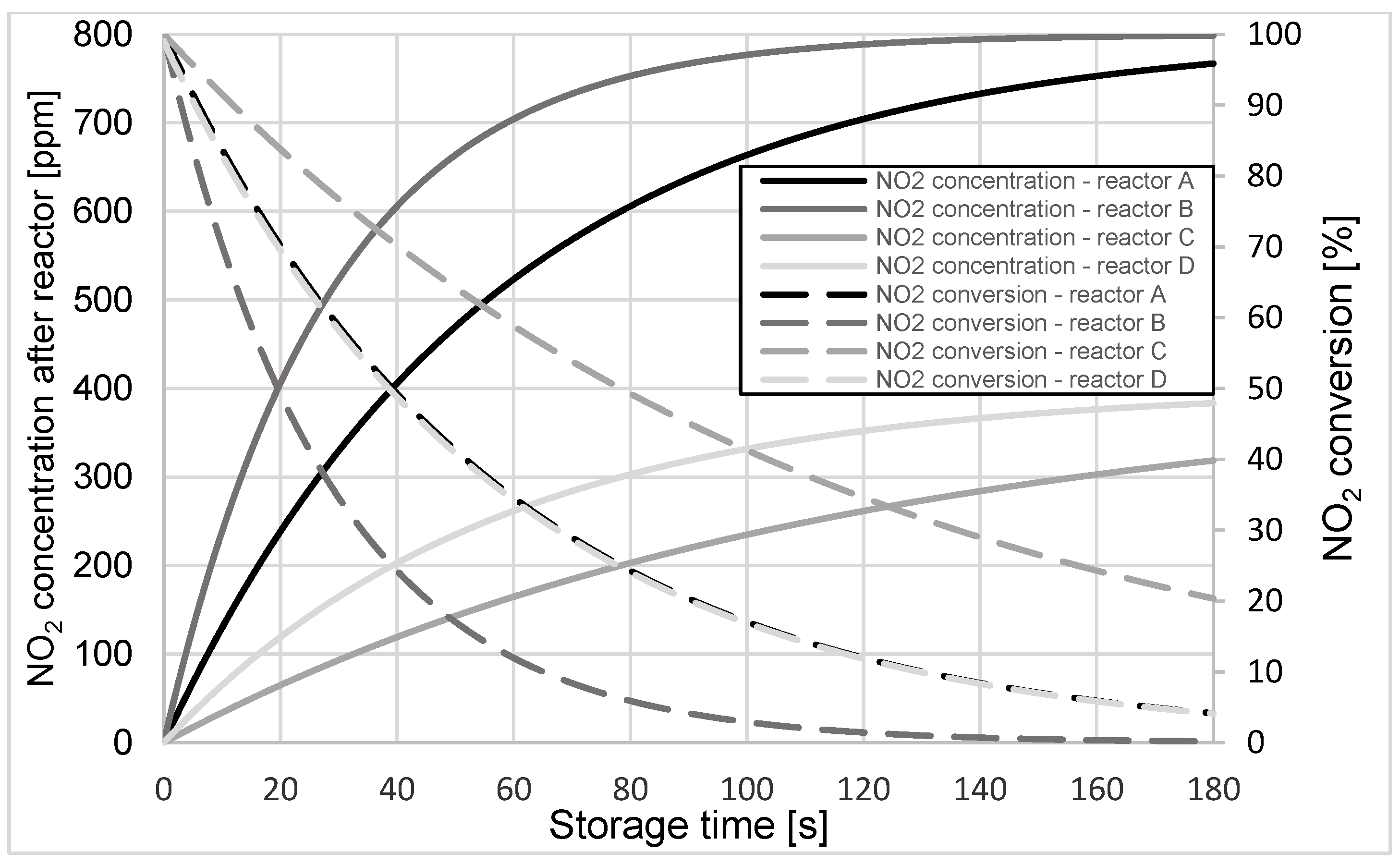
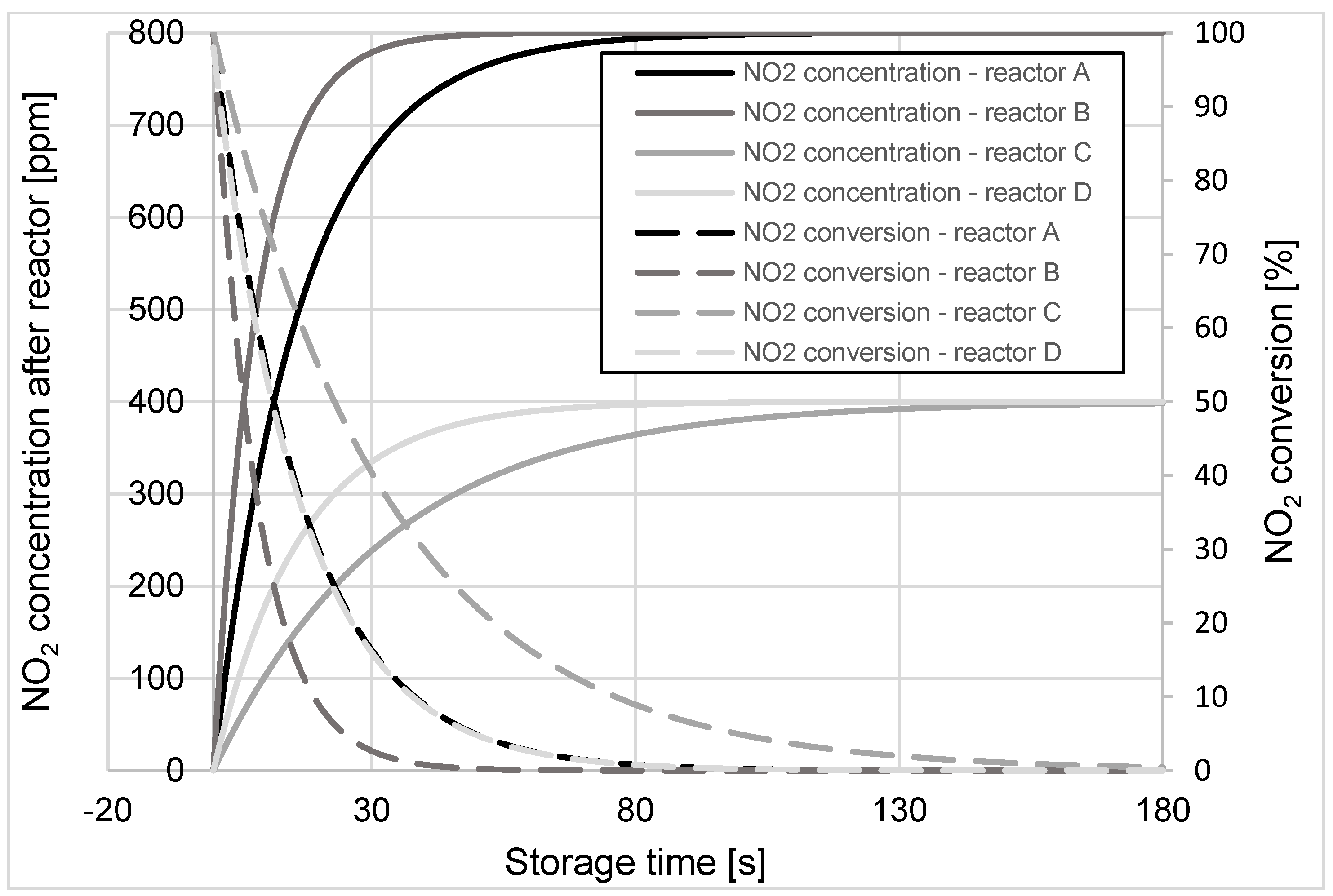
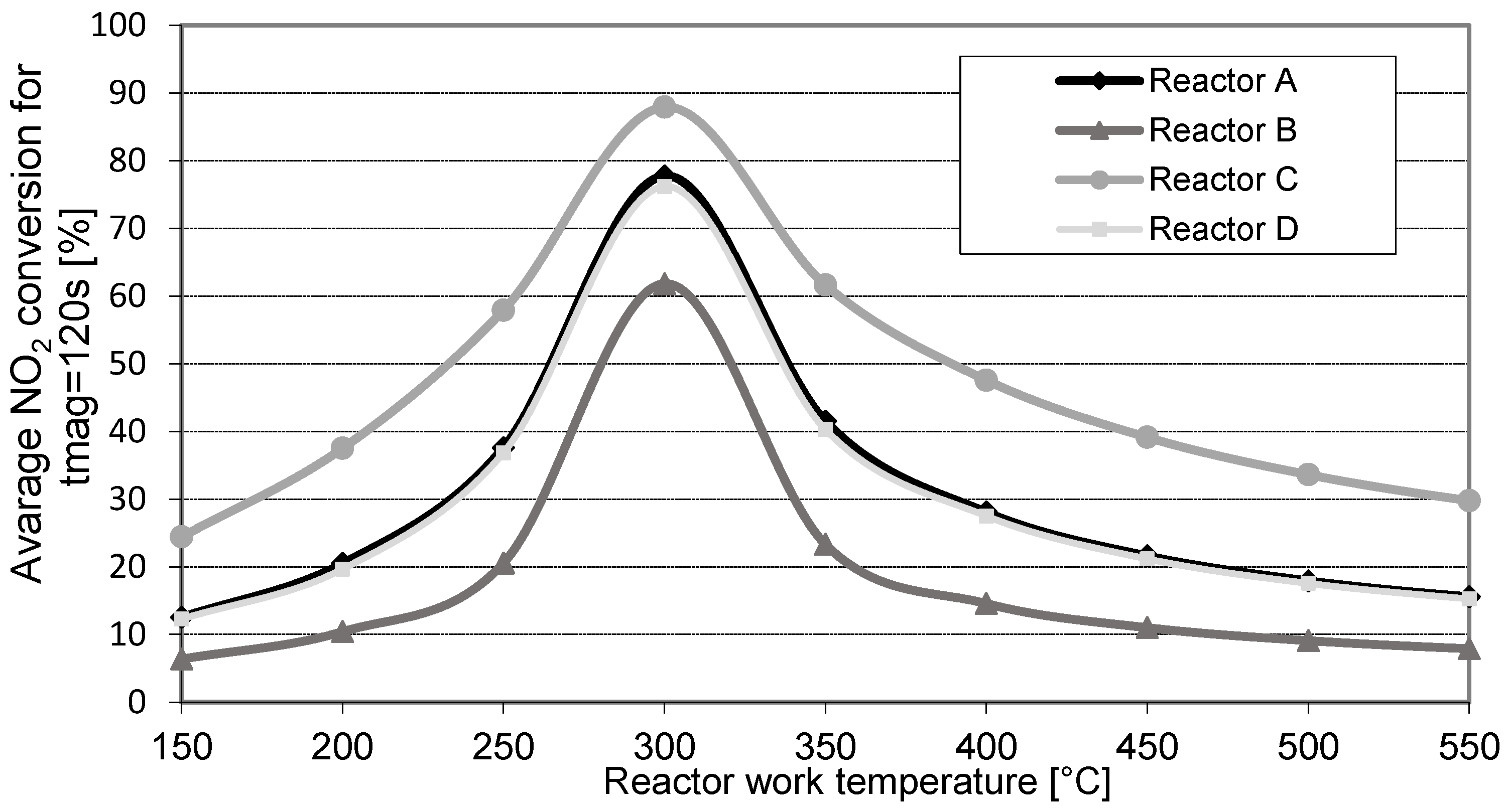
  • Reactor A, with a NO2 storage capacity of 380 g/m3, which corresponds to a reactor containing 30 g/dm3 of storage compound, and a simulated NO2 concentration at its inlet of 800 ppm;
  • Reactor B, with a NO2 storage capacity of 190 g/m3, which corresponds to a reactor containing 15 g/dm3 of storage compound, and a simulated NO2 concentration at its inlet of 800 ppm;
  • Reactor C, with a NO2 storage capacity of 380 g/m3, which corresponds to a reactor containing 30 g/dm3 of storage compound, and a NO2 concentration at its inlet of 400 ppm;
  • Reactor D, with a NO2 storage capacity of 190 g/m3, which corresponds to a reactor containing 15 g/dm3 of storage compound, and a NO2 concentration at its inlet of 400 ppm.
Simulation calculations of changes in NO2 concentration at the reactors’ outlets were carried out for the cases mentioned above. The instantaneous values of NO2 conversion in these reactors were determined for selected operating temperatures from 150 ÷ 600 °C in increments of 50 °C. Figure 3, Figure 4 and Figure 5 compare the results of simulation calculations of changes in NO2 concentration and the obtained conversion values of this compound during the storage process for reactor operating temperatures of 200, 350, and 600 °C, respectively.
Analogous calculations of the instantaneous values of NO2 concentration and its conversion for the four test cases were performed for the remaining temperature values (150 ÷ 600 °C). Based on these calculation results, the importance of the average NO2 conversion levels in the reactor during 120 s of the storage process was determined. Estimates were made at 120 s because under real operating conditions (actual reactors mounted in the exhaust system of the vehicle) LNT reactors are filled with NO2 (end of storage period), after approximately 120 s of engine operation on a lean mixture (NO2 storage). The results obtained during these calculations are shown in Figure 6.
Given analysis of the results presented in Figure 6, it can be concluded that the proposed mathematical model of the NO2 storage process is consistent with the theoretical basis of the operation of LNT reactors. For clarification:
  • Based on the calculation results obtained for reactor A, reducing the total storage capacity of the reactor by half (reactor B) significantly reduced its ability to convert NO2.
  • Reducing the amount of NO2 flowing into the reactor by half while maintaining its original storage capacity (reactor C) significantly improved the conversion properties of this toxic compound with regard to the base reactor (reactor A).
  • The calculations also showed that the NO2 storage capacity of the reactor with twice the capacity (reactor D) was identical to the concentration of nitrogen oxides at its inlet; i.e., twice as low as for the reactor with double the storage capacity but twofold the concentration of NO2 at its inlet (reactor A).

4. Conclusions

Based on the results of simulation calculations for the modeled operating conditions of the reactor, the following conclusions can be made:
  • The mathematical model of the NO2 storage process developed and proposed by this paper’s authors is innovative. It considers the impact of a reactor’s storage capacity, the NO2 concentration at its inlet, and its operating temperature on changes in the instant NO2 concentration at its outlet.
  • This paper’s content is essential because it relates directly to NO2 storage reactors operating with a lean mixture in the engine. This is crucial because lean mixtures currently power most modern internal combustion engines. Additionally, one of the main problems is the reduction of nitrogen oxides in lean exhaust gases.
  • The results presented herein were developed based on the authors’ knowledge regarding the NO2 storage capacity of alkaline earth metal oxides and research data on the influence of external factors (such as temperature or the active surface of the reactor) on the course of the NO2 storage process in LNT reactors. The results appeared consistent with data presented in the relevant literature [7,8,10,17,18].
  • The simulation calculations presented in this paper are innovative. They are based on the theoretical calculation model previously proposed by the authors, and the maximum storage capacity of an LNT reactor, based on actual physicochemical studies of its active surface.
  • It can initially be stated that the developed mathematical model of the storage process allows accurate reproduction of the substantial loss of NO2 storage capacity in LNT reactors. In the future, it can be used to simulate calculations allowing a preliminary estimation of the storage process of this type of reactor under various operating conditions.
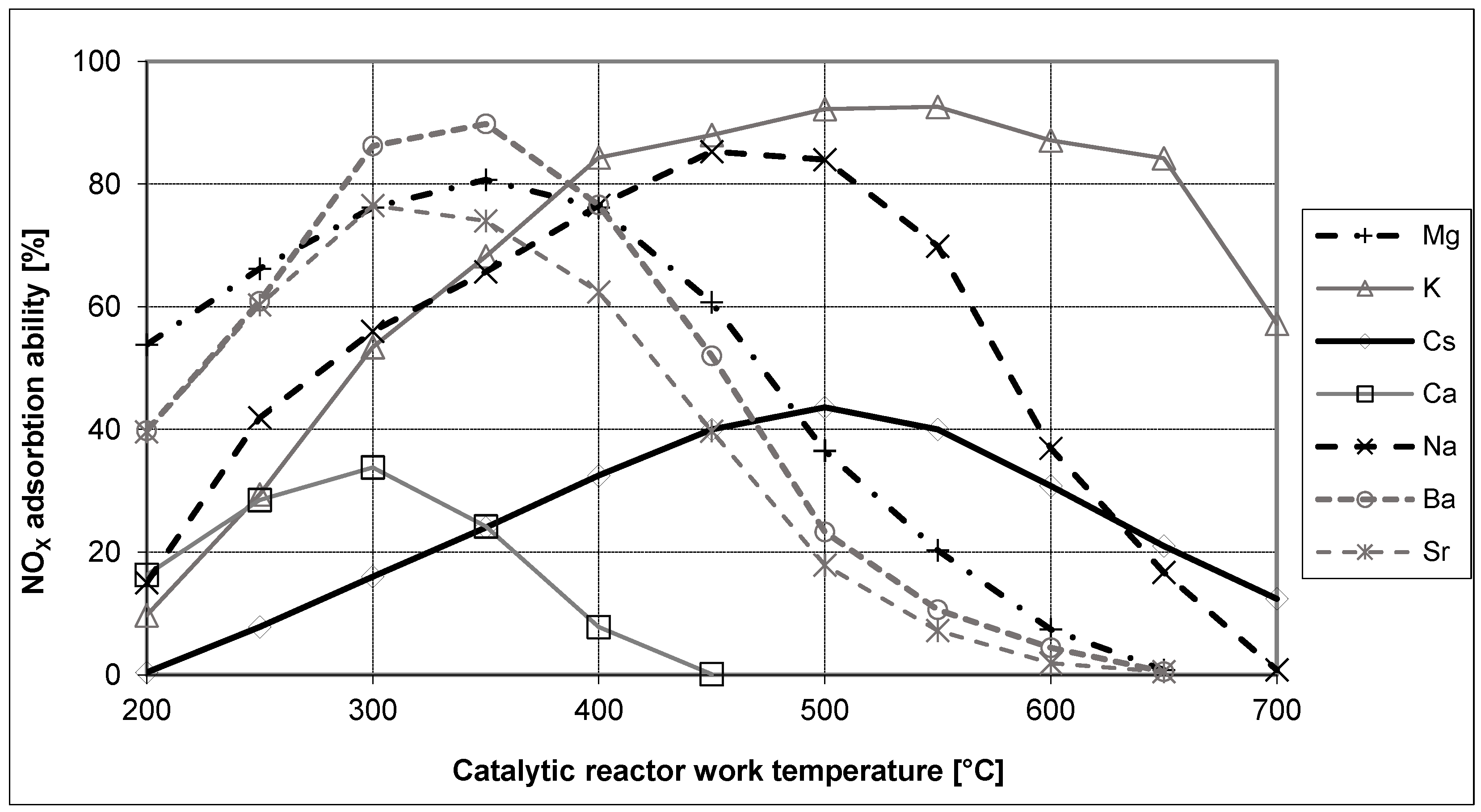
  • Research identifying the value of the Km coefficient as a parameter responsible for changes in the reactor storage efficiency as a function of its operating temperature will allow it to be used as a parameter that determines the type of storage substrate used in a reactor (e.g., Ca, Na, Cs, Ba, Mg, etc.).
  • To verify the proposed model of NO2 storage in an LNT reactor thoroughly, results of simulation calculations should be compared with experimental results carried out on real LNT reactors.
  • Ultimately, identification and calibration of the developed model will create the possibility of obtaining a tool that initially assesses the NO2 storage process in LNT reactors under various operating conditions without conducting costly and long-term experimental studies. This tool will allow initial rejection of unfavorable solutions. As a result, it will reduce the costs and time associated with research regarding solutions that do not bring prospects in a later actual application.
  • Further work on this model should focus on an extended study of the influence of external factors (ambient temperature and pressure) on the operation of the catalytic converter, taking into account other elements of alkali metal group.

Author Contributions

Conceptualization, W.K. and M.K.W.; methodology, W.K.; software, W.K. and M.K.W.; validation, W.K. and M.K.W.; formal analysis, W.K. and P.O.; investigation, W.K. and M.K.W.; resources, P.O.; data curation, M.K.W.; writing—original draft preparation, W.K.; writing—review and editing, M.K.W.; visualization, W.K.; supervision, P.O.; project administration, P.O.; funding acquisition, M.K.W. All authors have read and agreed to the published version of the manuscript.

Funding

This research received no external funding.

Data Availability Statement

The group data presented in this study are available on request from the corresponding author. The individual data are not publicly available due to privacy and confidentially.

Conflicts of Interest

The authors declare no conflict of interest.

References

  1. Pielecha, J.; Magdziak, A.; Brzeziński, L. Nitrogen oxides emission evaluation for Euro 6 category vehicles equipped with combustion engines of different displacement volume. IOP Conf. Ser. Earth Environ. Sci. 2019, 214, 01201. [Google Scholar] [CrossRef]
  2. Kruczyński, P.; Orliński, P.; Kamela, W.; Ślęzak, M. Analysis of selected toxic components in the exhaust gases of a CI engine supplied with water-fuel emulsion. Pol. J. Environ. Stud. 2018, 27, 129–136. [Google Scholar] [CrossRef]
  3. Ambrozik, A.; Ambrozik, T.; Łagowski, P. Fuel impact on emissions of harmful components of the exhaust gas from the CI engine during cold start-up. Maint. Reliab. 2015, 17, 95–99. [Google Scholar] [CrossRef]
  4. Hilliard, J.C.; Springer, G.S. (Eds.) Fuel Economy. In Road Vehicles Powered by Spark Ignition Engines; Springer Science & Business Media: Berlin/Heidelberg, Germany, 2013. [Google Scholar]
  5. Doǧan, H.E.; Kutlar, O.A.; Javadzadehkalkhoran, M.; Demirci, A. Investigation of burn duration and NO emission in lean mixture with CNG and gasoline. Energies 2019, 12, 4432. [Google Scholar] [CrossRef] [Green Version]
  6. Heck, R.M.; Farrauto, R.J. Automobile exhaust catalysts. Appl. Catal. A Gen. 2001, 221, 443–457. [Google Scholar] [CrossRef]
  7. Mahzoul, H.; Brilhac, J.F.; Gilot, P. Experimental and mechanistic study of NOx adsorption over NOx trap catalysts. Appl. Catal. B Environ. 1999, 20, 47–55. [Google Scholar] [CrossRef]
  8. Forzatti, P.; Castoldi, L.; Lietti, L.; Nova, I.; Tronconi, E. Identification of the reaction networks of the NOx storage/reduction in lean NOx trap systems. Stud. Surf. Sci. Catal. 2007, 171, 175–208. [Google Scholar] [CrossRef]
  9. Aaron Michael, W. Lean NOx Trap Catalysis for Lean Burn Natural Gas Engines. Master’s Thesis, University of Tennessee, Knoxville, TN, USA, 2004. [Google Scholar]
  10. Lietti, L.; Castoldi, L. (Eds.) NOx trap catalysts and technologies: Fundamentals and industrial applications. R. Soc. Chem. 2018, 33. [Google Scholar] [CrossRef]
  11. Isermann, R. Engine Modeling and Control; Springer: Berlin/Heidelberg, Germany, 2014. [Google Scholar] [CrossRef]
  12. Hepburn, J.S.; Thanasiu, E.; Dobson, D.A.; Watkins, W.L. Experimental and modeling investigations of NOx trap performance. SAE Tech. Pap. 1996. [Google Scholar] [CrossRef]
  13. Laidler, K.J. The development of the arrhenius equation. J. Chem. Educ. 1984, 61, 494. [Google Scholar] [CrossRef]
  14. Gieshoff, J.; Schäfer-Sindlinger, A.; Spurk, P.C.; Van Den Tillaart, J.A.A.; Garr, G. Improved SCR systems for heavy duty applications. SAE Tech. Pap. 2000. [Google Scholar] [CrossRef]
  15. Kamela, W.; Kruczyński, S.W.; Orliński, P.; Wojs, M.K. Ocena wpływu ładunku platyny na redukcję NOX w reaktorze Pt/Al2O3. Zeszyty Naukowe IP 2012, 1, 197–204. [Google Scholar]
  16. Kamela, W. Analiza Możliwości Zastosowania Tlenków Metali Alkalicznych Jako Składników Magazynujących NOX w Reaktorach Katalitycznych. Master’s Thesis, Warsaw University of Technology, Warsaw, Poland, 2007. [Google Scholar]
  17. Pereda-Ayo, B.; González-Velasco, J.R.; Burch, R.; Hardacre, C.; Chansai, S. Regeneration mechanism of a Lean NOx Trap (LNT) catalyst in the presence of NO investigated using isotope labelling techniques. J. Catal. 2012, 285, 177–186. [Google Scholar] [CrossRef]
  18. Lv, L.; Wang, X.; Shen, M.; Zhang, Q.; Wang, J. The lean NOx traps behavior of (1–5%) BaO/CeO2 mixed with Pt/Al2O3 at low temperature (100–300 °C): The effect of barium dispersion. Chem. Eng. J. 2013, 222, 401–410. [Google Scholar] [CrossRef]
Figure 1. Diagram of the nitrogen oxide storage process in an LNT reactor.
Energies 15 07819 g001
Figure 2. Nitrogen oxide adsorption efficiency for selected alkali metals [12].
Energies 15 07819 g002
Figure 3. Changes in NO2 concentration and its conversion during the storage process in A, B, C, and D reactors at the operating temperature of 200 °C.
Energies 15 07819 g003
Figure 4. Changes in NO2 concentration and its conversion during the storage process in A, B, C, and D reactors at the operating temperature of 350 °C.
Energies 15 07819 g004
Figure 5. Changes in NO2 concentration and its conversion during the storage process in A, B, C, and D reactors at the operating temperature of 600 °C.
Energies 15 07819 g005
Figure 6. Changes in the average NO2 conversion as a function of the operating temperature of reactors A, B, C, and D for the storage process of 120 s.
Energies 15 07819 g006
Publisher’s Note: MDPI stays neutral with regard to jurisdictional claims in published maps and institutional affiliations.

