Article

Frequency of Damage of Low Voltage Apparatus Due to Lightning Flashes to Ground Nearby HV Overhead Lines

by
Tomasz Kisielewicz
1,*,
Giovanni Battista Lo Piparo
2 and
Carlo Mazzetti
3
1
Electrical Department, Warsaw University of Technology, 00-661 Warsaw, Poland
2
TC 81, IEC, 1211 Genève, Switzerland
3
Department of Astronautical, Electrical and Energy Engineering, University of Rome “La Sapienza”, 00-184 Rome, Italy
*
Author to whom correspondence should be addressed.
Energies 2022, 15(20), 7809; https://doi.org/10.3390/en15207809
Submission received: 16 September 2022 / Revised: 6 October 2022 / Accepted: 17 October 2022 / Published: 21 October 2022

Abstract

:
The paper deals with a simplified approach to evaluate the frequency of damage of low voltage apparatus powered by a in housing HV/LV transformer against overvoltages due to nearby lightning flashes (source of damage S4 according to IEC 62,305 standard). The approach is based on computer simulations with validated models according to the current state of the art. The paper evaluates: the overvoltages stressing the HV/LV transformer due to lightning-induced over-voltages on the supplying HV overhead line; the voltage transferred to low voltage circuit through the power transformer and the influence of the transformer characteristics and of the LV circuits feeding the apparatus; the influence of the characteristics and the number of LV circuits on the frequency of damage of the apparatus. The different contributions to the voltage at the apparatus terminals, namely, the voltage transferred by the HV/LV transformer and the voltage induced by lightning current in the circuit downstream the transformer, are recognized. The voltage drop along the earthing system between the points where the transformer and the apparatus are earthed is, in the case considered, not effective because the apparatus and the transformer are bonded at the same point to the earthing system of the electrical installation. Even if these voltage components exhibit different shape and time at peak, for safety, they are added. When the resulting voltage is higher than the rated impulse voltage of apparatus insulation, damage of apparatus occurs. The evaluation allows to conclude that the frequency of damage of the LV apparatus supplied by circuits in a multipolar cable is about a thousand times lower than the one relevant to circuits in plastic conduit. If the tolerable frequency of damage of the LV apparatus is kept in the range of 0.01 damage/year, the adoption of protection measures against overvoltages caused by the source S4 is practically not necessary, except for the case of long circuits in conduit, powered by long HV overhead lines in areas with high values of lightning flash density. As this matter has not yet been considered in the IEC 62305 standard series, the results presented in this paper will be useful in the light of the revision of requirements of this standard.

1. Introduction

Overvoltages caused by lightning strikes can interrupt regular operations of electronic and electrical devices. The lightning influence on the apparatus operations depends on many factors. Overall, the type of natural overvoltage is decisive in selecting protection systems, but the internal and installation characteristics of these systems should also be carefully considered. From a protective point of view, it is possible to distinguish between lightning flashes to the structure, lightning flashes near the structure, and flashes to or near the lines. In principle, the apparatus can be classified by impulse withstand voltage (Uw). It is important to mention that if Uw is exceeded, the apparatus connected to the system is damaged, and consequently, interruption of service continuity appears.
In order to ascertain if protection against lightning overvoltages is needed or not, in the IEC standard [1], the concept of frequency of damage that may impair the availability of the internal systems within the structure has been introduced.
Protection against lightning is needed if the frequency of damage is higher than the tolerable level. In this case, protection measures shall be adopted in order to reduce the frequency of damage of the apparatus to no more than the tolerable level.
A method is given in the standard [1,2] to evaluate such frequency of damage by distinguishing the contribution of flash to the structure where the apparatus is installed, flash to the supplying line, and flash to ground, but only the case of apparatus directly connected to LV lines is considered.
In contributions [3,4], another type of damage of apparatus connected to an overhead LV power line is considered where particular attention is paid to the SPD system dimensioning. The proposed methodology can be useful to properly select and install an SPD system with a given probability.
However, in most facilities such as factories, commercial buildings, office buildings, service buildings, etc., internal power system includes an HV/LV transformer. Consequently, protective features changed under such conditions. It is important to mention that the overvoltages transmitted by the transformer winding may exceed the rated surge voltage withstand by the apparatus, especially in the case of the HV overhead line. Moreover, in such conditions, induced overvoltages shall be carefully considered. The acronym HV is used in standards to indicate an AC voltage which exceeds 1000 V; in current technical language, it is often replaced by MV (medium voltage) for voltages no higher than 60 kV.
In recent papers [5,6], a simplified approach to evaluate the damage probability of apparatus powered by an HV/LV transformer due to lightning strokes to the structure where the apparatus is installed as well as due to lightning to the overhead line supplying the apparatus is presented and discussed.
The aim of the present paper is to give a practical approach to evaluate the frequency of damage of apparatus within a structure in case of lightning flashes to ground and, consequently, ascertain the need to provide or not appropriate protection measures and, among these, the SPD system.
The approach is based on the modelling of electrical system and on the computation of:
  • The voltage induced by lightning on HV power line, already extensively studied by using the LIOV-EMTP code [3,6,7,8,9,10];
  • The transfer of overvoltages across the HV-LV transformer and the voltage induced by lightning current in the LV circuit, by using the EMTP-RV transient software.
Different parameters influencing the values and the shapes of the voltages have been considered, such as the characteristics of the HV line and of HV/LV transformer, the number and characteristics of LV circuits, the value and shape of inducing stroke current, and soil conductivity.
As a result, analytical expressions and graphs are provided which allow a simplified assessment of the damage frequency of the LV apparatus.
The paper is organized as follows: Section 2 gives a schematic representation of the system under consideration and the basic information on the models used in the computer simulation; in Section 3, the overvoltages stressing the primary of the HV/LV transformer are calculated and analyzed; in Section 4, the transfer of voltage from the primary to the secondary of the transformer is considered; in Section 5 and Section 6, the voltage induced by lightning current in the low voltage circuit and the voltage on the apparatus terminal are calculated and the results discussed; Section 7 is focused on the frequency of damage of the low voltage apparatus; in Section 8, the main conclusions of the results presented in this paper are summarized.
As this matter has not yet been considered in the IEC 62,305 standard series, the results presented in this paper will be useful in the light of the revision of requirements of this standard.

2. Case Study under Consideration

In the paper, the induced effect of lightning is considered. A schematic representation of the analyzed system is shown in Figure 1.
The simulation aspects, namely, modeling of the electrical system and calculation methods of induced overvoltages caused by lightning discharges, have been widely studied [3,4,5,6,7,8,9,10,11,12,13,14,15,16,17,18,19,20]. It is important to stress that analysis reported contains various parameters influencing the shape of induced overvoltages, namely, peak values and shapes. The surge conditions are determined by the system configuration and, consequently, by the line length, line terminations, soil conductivity, and lightning parameters.
In addition, the simulation models and number of calculated distributions of induced overvoltages with amplitude exceeding a certain value UH [kV] referred to a determined case are in line with comparable results obtained by other investigators [7,8,9].
A typical HV supply overhead line 1000 m long with 100 m span is analyzed [21]. The high of the poles is 10 m, the conventional earth impedance Zp = 50 Ω is considered. The overhead line terminations consist of HV/LV transformer and a matched HV overhead line. In principle, the surge parameters, namely, wave shape of the overvoltage UH, and a large variety of waveforms can be found in the literature depending on the type of the line and the other influencing parameters. In the current analysis according to the experimental and theoretical investigations, the typical wave shape 5/20 µs is assumed as representative of the first stroke of negative flashes [10]. This wave shape is reproduced and simulated by means of the so called Heidler function, applicable to the lightning current simulations [1].
For the sake of safety, the effect of flashovers at the pole insulators is neglected.
The HV/LV transformer characteristics under transient conditions are adopted from [22]. The circuit configuration and relative components and their values are reproduced in line with [22], taking into account 75 kVA transformer features.
The analyses reported in the current paper were obtained using EMTP-RV transient software. The models used refer to the current achievements in the field of power system protection. In particular the analysis consists of evaluation of voltage UA at apparatus terminals. It is important to stress that the models used are validated mathematically or through laboratory comparative studies/tests [23,24,25,26,27,28,29,30,31,32,33,34,35,36,37,38,39]. The simulations take into account necessities of simulation and experimental results comparison.
In the present work, only overvoltages in common mode are considered.

3. Overvoltages Induced in the HV Line

The voltage UH induced by a lightning strike to earth on a conductor of a line depends on the height h of the conductor, the distance d between the lightning and the line, the soil resistivity ρ, and the waveform of the lightning current [14,15,16,17,18].
The number NI that a lightning striking the ground and inducing a given voltage equal to the rated impulse voltage of the transformer HV winding insulation UH = UWH depends not only on the aforementioned parameters but also on the length L of the line; for a line of high h and length L, it is generally accepted that NI can be calculated by the following simplified equation [12]:
NI = NGLa/UHb (events/year)
and then
UH = (NGLa/NI)1/b (kV)
where NG is the ground flash density of the region where the line is installed; L is expressed in km and h in meters. These formulas assume UH Ո h.
For evaluation of NI in a finite length line, values of coefficients a and b depend on the line length, due to the boundary effect at open line end, which considers the induced surges due to flashes to ground in front of the end of the line.
In Figure 2, the values of the coefficients a and b are shown, derived from simulations carried out with the LIOV—EMTP method for a LV line without line flashover, L = 500 m long, closed on MV/LV transformer at one end and open at the other; the line conductor height was h = 6 m.
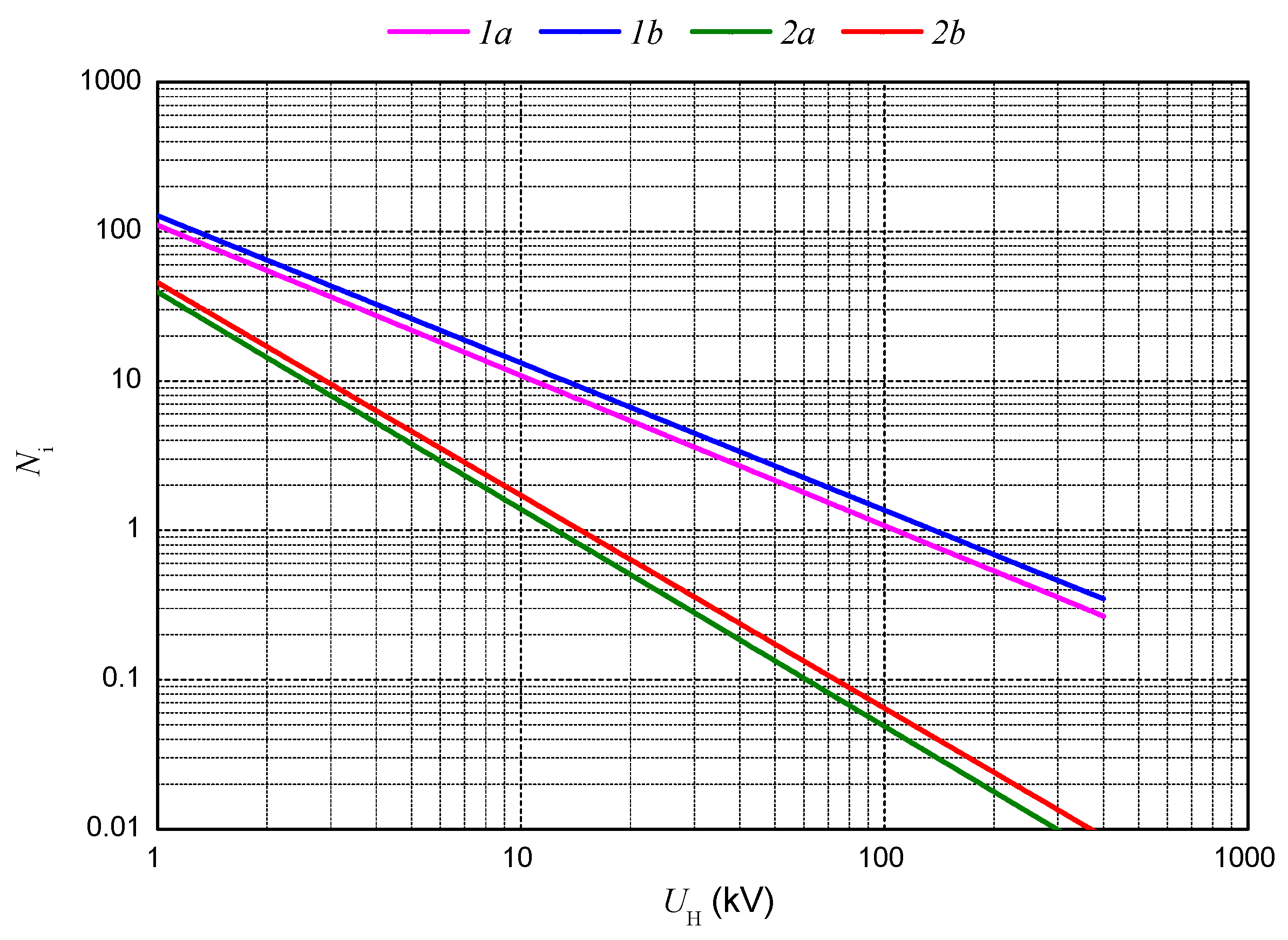
The number NI of lightning events per year and per NG = 1 strokes/km2·year, inducing in a HV line (h = 10 m; no ground wire) voltages to ground UH, is reported in Figure 3 for some values of soil resistivity ρ and line length L.

4. Overvoltages Transfer through HV/LV Transformer

The value of coefficient CT consists of the ratio between the peak values of the voltage UL at the secondary and that UH at the primary (CT = UL/UH) of overvoltages appearing an HV/LV transformer [40,41,42]. In principle, the CT value increases with the slope of the wave front of the HV voltage and decreases as the capacitance of the connected LV circuits increases. The impact of the LV circuits connected to the HV/LV transformer on the coefficient CT value is shown in Figure 4. The CT value as function of the length LC of the circuits is reported. Moreover, Figure 5 illustrates reduction factor kCT of coefficient CT as function of number nc of the connected unshielded LV circuits [2].

5. Overvoltages Induced in the LV Circuits

The voltage Uind induced by a lightning strike to earth on a LV circuit essentially depends on the area S of the loop formed by the conductors of the circuit, on the orientation of the loop with respect to the path of the lightning current, on the distance d between the lightning and the loop, and on the waveform of the inducing lightning current and its probability distribution.
For a random oriented loop, the number of times NI that a lightning strike on the ground induces a given voltage Uind can be calculated by the following simplified formulas [3]:
NI = NGAeq = NGπreq2 ∙ 10−6 (events/year)
where req = 7.07 ∙ S/Uind (m) with S in m2 and Uind in kV, and then
Uind = S ∙ (157 ∙ NG/NI)0.5 ∙ 10−3 (kV)

6. Apparatus Voltage UA

As discussed in papers [4,5], in case of direct flashes to the structure (S1 according to the standard nomenclature), the voltage UA at apparatus terminals is determined by:
  • The voltage UTR, namely, voltage transferred by the winding of HV/LV transformer which propagates along the LV circuit and is reflected on the terminals of the apparatus, where the condition of open circuit is assumed;
  • The voltage drop ΔU along the earthing system between the points where the transformer and the apparatus are earthed;
  • The voltage Uind induced by lightning current in the LV circuit downstream the transformer.
As already noted in [5], the three voltage components exhibit different shape and different time to peak; for the sake of safety, it may be assumed:
UA = UTR + ΔU + Uind
The voltage UTR depends on the transfer coefficient CT and on the reflection coefficient of the LV circuit kr = UTR/UL [4,24,42]
UTR = kr*CT*UH
The maximum value of UTR occurs at the HV transformer winding withstand voltage UH = UWH:
UTRmax = kr*CT*UWH
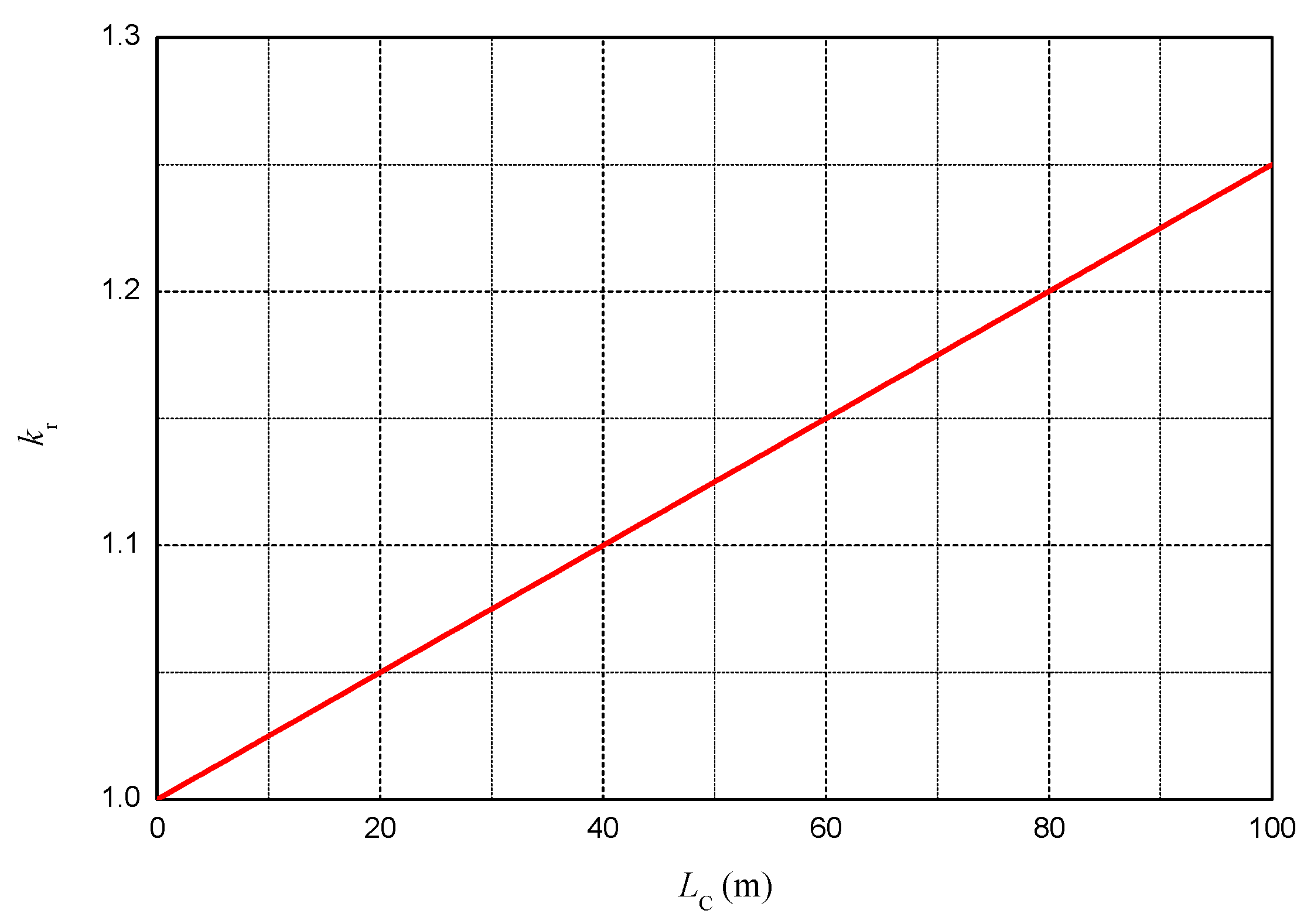
The reflection coefficient kr of the LV circuit depends on the risetime of the overvoltage wave UL and on the time it takes to travel the circuit from the HV/LV transformer to apparatus, and then, it depends on the length Lc of the LV circuit.
Values of the reflection coefficient kr are reported in Figure 6 as a function of the length Lc of the LV circuit.
The potential difference ΔU depends on the relative position of the points where the transformer and the apparatus are bonded to the earthing system and on the soil resistivity [14,15,43]. This component works when the breakdown transformer HV windings occurs, and the apparatus is earthed at a point different from that of the transformer (locally earthed). Otherwise, it is ΔU = 0.
The voltage Uind, by lightning current in the LV circuit, depends on the area of the loop formed by the conductors of the LV circuit.
Unless otherwise specified, the evaluation was performed for the typical case of more than one LV circuit connected to the HV/LV transformer, assuming:
  • HV line nominal voltage U0 = 20 kV;
  • LV apparatus withstand voltage UW = 2.5 kV;
  • Apparatus is earthed in the same point as the transformer (apparatus not locally earthed, it is ΔU = 0);
  • LV circuit length LC = 50 m;
  • Number of LV connected circuits nc = 4;
  • HV Line length L = 1 km;
  • Ground resistivity ρ = 500 Ωm.
The trend of the voltage components that build up the voltage UA is shown in Figure 7 for LV circuits in conduit and in Figure 8 for LV circuits in multipolar cable.
Note that for values of the voltage UH higher than the withstand voltage UWH at the primary of the transformer, the voltage transmitted to the secondary of the transformer does not vary as the number NI of voltages induced on the HV line varies; in other words, in these conditions, the value of UTR is independent of the length L of the HV line.

7. LV Apparatus Damage Frequency

The frequency of damage to the LV apparatus is the value NI which satisfies Equation (5) by imposing UA = UWA.
Such value of NI depends on several factors such as the lightning flash density NG, the ground resistivity ρ, the HV/LV transformer characteristics (UWH, CT), the HV line characteristics (h; L), the number nc of connected LV circuits and their characteristics (w; lc), and the withstand voltage of the apparatus UWA.
In the worst case of high resistivity soil (ρ ≥ 500 Ωm), for apparatus with UWA = 2.5 kV and a normalized HV line (NG = 1 flash per km2 per year, h = 10 m; L = 1 km), the dependence of the frequency of damage Ni was assessed:
  • On the length lc of LV circuits; see Figure 9;
  • On the type of LV circuit (identified by the distance w between the conductors); see Figure 10;
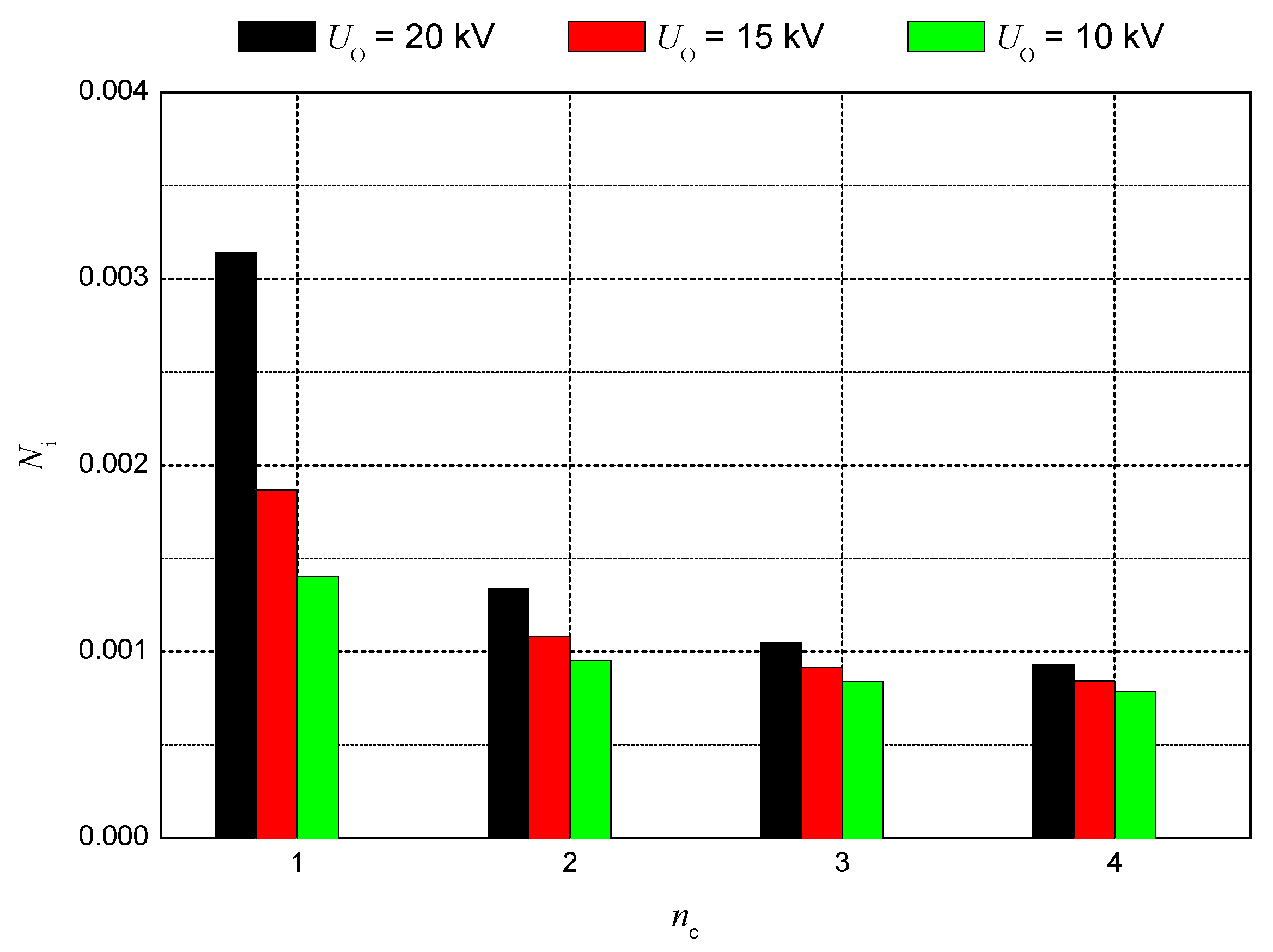
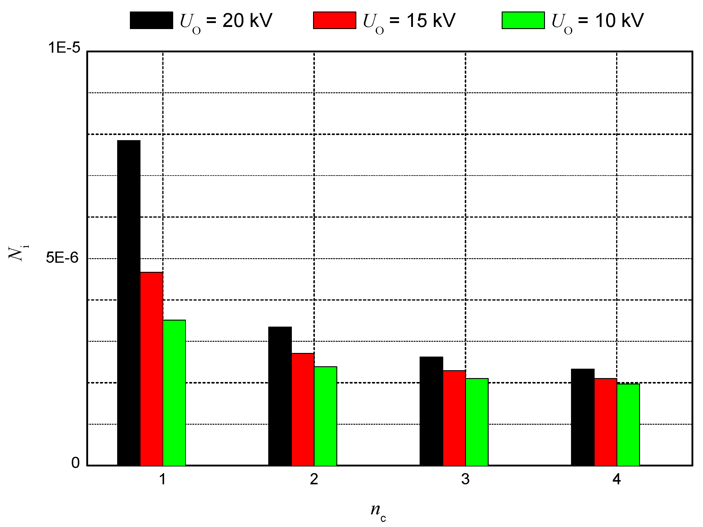
  • On the number nc of connected LV circuits; see Figure 11 and Figure 12;
  • On the withstand voltage UWA of LV apparatus; see Figure 13 and Figure 14.
If a frequency of damage (NI < 10−2) is assumed as practically negligible, it should be noted that:
  • For LV circuits in a multipolar cable, protective measures against overvoltages due to the source of damage S4 are not needed, even in the most severe cases, such as HV lines several km long, soils with resistivity of several hundreds of Ωm, high values of NG, and LV circuits several tens of meters long, powered by HV/LV transformers with primary rated voltage of up to 20 kV; see Figure 12 and Figure 14;
  • For LV circuits in conduit, protective measures could be needed, only in the extraordinary case of product NG ·L being not greater than ten and apparatus withstanding voltage UW not lower than 2,5 kV; see Figure 13.

8. Conclusions

An approach has been presented and discussed to evaluate the frequency of damage of low voltage apparatus powered by a in housing HV/LV transformer against overvoltages due to nearby lightning flashes.
Based on preliminary results of application, the following conclusions can be formulated:
  • A typical 5/20 µs waveform can be assumed as typical of the UH voltages induced on the HV line; a waveform with a similar rise time also characterizes the UL voltage transmitted to the LV circuits through the HV/LV transformer;
  • For values of the voltage UH higher than the withstand voltage UWH at the primary of the transformer, the voltage transmitted to the secondary of the transformer is independent of the length L of the HV line;
  • The transfer coefficient CT of overvoltages through an HV/LV transformer, intended as the ratio between the peak values of the voltage UL at the secondary and that UH at the primary (CT = UL/UH), increases with the slope of the wave front of the HV voltage and decreases as the number and the length of the connected LV circuits increase;
  • The HV/LV transformer significantly reduces common mode overvoltages: the value of transfer coefficient CT consists of a few percent, or even less if the internal circuit configuration on the LV side is complex;
  • Due to times at the peak of the voltage UL, in the order of some microseconds, the propagation coefficient kr along the LV circuit exhibits values close to unity, even for circuits of considerable length;
  • The overvoltage stressing the apparatus is mainly due to induction phenomena by the lightning current flowing to ground nearby the HV line; indeed, these overvoltages increase as the area of induction loop (length and width of circuit) increases;
  • The frequency of damage of LV apparatus supplied by circuits in multipolar cable is about a thousand times lower than the one relevant to circuits in plastic conduit;
  • The frequency of damage of the LV apparatus increases weakly as the HV line nominal voltage increases;
  • For a tolerable frequency of damage of reasonable value, the use of protection measures of the LV apparatus against overvoltages caused by the source S4 is practically not necessary. Exceptional cases of long circuits in conduit, powered by long HV overhead lines in areas with high NG values, are usually covered by the LV SPDs installed for protection against overvoltages due to sources S1 and S3.

Author Contributions

Conceptualization, T.K., G.B.L.P. and C.M.; Formal analysis, T.K. and G.B.L.P.; Investigation, T.K. and G.B.L.P.; Methodology, T.K., G.B.L.P. and C.M.; Supervision, T.K., G.B.L.P. and C.M. All authors have read and agreed to the published version of the manuscript.

Funding

This research was funded in part by the Warsaw University of Technology, Poland, and University of Rome “La Sapienza”, Italy.

Acknowledgments

The paper has been prepared in the frame of international cooperation between Poland and Italy. The authors wish to express their gratefulness to the authorities of Warsaw University of Technology and University of Rome “La Sapienza” for relative support.

Conflicts of Interest

Declare conflicts of interest or state.

References

  1. IEC 62305-1; Protection against Lightning—Part 1: General Principles. 2nd ed. IEC: Geneva, Switzerland, 2010.
  2. IEC 62305-4; Protection Against Lightning—Part 4: Electrical and Electronic Systems within Structures. 2nd ed. IEC: Geneva, Switzerland, 2010.
  3. Marzinotto, M.; Fiamingo, F.; Mazzetti, C.; Lo Piparo, G.B. Quality of the supplied electric service: A tool to evaluate the need of protection against lightning surges. Electr. Power Syst. Res. 2012, 85, 75–81. [Google Scholar] [CrossRef]
  4. Kisielewicz, T.; Lo Piparo, G.B.; Napolitano, F.; Mazzetti, C.; Nucci, C.A. SPD dimensioning in front of indirect flashes to overhead low voltage power lines. In Proceedings of the 15 IEEE International Conference on Environment and Electrical Engineering, Rome, Italy, 10–13 June 2015. [Google Scholar]
  5. Kisielewicz, T.; Lo Piparo, G.B.; Mazzetti, C. Simplified approach for protection of apparatus powered by an HV/LV transformer against lightning strokes to the structure. In Proceedings of the 22 IEEE International Conference on Environment and Electrical Engineering, Prague, Czech Republic, 28 June–1 July 2022. [Google Scholar]
  6. Piantini, A.; Janiszewski, J.M. An experimental study of lightning induced voltages by means of a scale model. In Proceedings of the 21st International Conference on Lightning Protection, Berlin, Germany, 22–25 September 1992. [Google Scholar]
  7. Rachidi, F.; Nucci, C.A.; Ianoz, M. Transient analysis of multiconductor lines above a lossy ground. IEEE Trans. Power Deliv. 1999, 14, 294–302. [Google Scholar] [CrossRef]
  8. Rachidi, F.; Loyka, S.L.; Nucci, C.A.; Ianoz, M. On the Singularity of the Ground Transient Resistance of Overhead Transmission Lines. In Proceedings of the 25th International Conference on Lightning Protection, Rhodos, Greece, 18–22 September 2000. [Google Scholar]
  9. Porrino, A.; Alexandri, I.; Clement, M.; Finlay, G.S.; Henriksen, T.; Hoeffelman, J.; Ishii, M.; Martinez Cid, P.; Nucci, C.A.; Po-polansky, F.; et al. Protection of MV and LV networks against lightning. I. Basic information, Electricity Distribution. Part 1: Contributions. CIRED. In Proceedings of the 14th International Conference and Exhibition on (IEE Conf. Publ. No. 438), Birmingham, UK, 2–5 June 1997; pp. 21/1–21/7. [Google Scholar]
  10. Eriksson, A.J. The incidence of lightning strikes to power lines. IEEE Trans. Power Deliv. 1978, 2, 859–870. [Google Scholar] [CrossRef]
  11. Kisielewicz, T.; Lo Piparo, G.B.; Mazzetti, C. Simplified evaluation of damage probability of apparatus powered by an HV/LV transformer due to lightning strokes to the overhead line. In Proceedings of the 22 IEEE International Conference on Environment and Electrical Engineering, Prague, Czech Republic, 28 June–1 July 2022. [Google Scholar]
  12. IEEE Standard 1410; IEEE Guide for Improving the Lightning Performance of Electric Power Overhead Distribution Lines. IEEE: New York, NY, USA, 2011.
  13. CIGRE-CIRED JWG C4.4.02; Protection of MV and LV Networks against Lightning. Part I: Common Topics. International Council of Large Electric Systems (CIGRE): Paris, France, 2006.
  14. Nucci, C.A. The lightning induced over-voltage (LIOV) code. In Proceedings of the 2000 IEEE Power Engineering Society Winter Meeting, Singapore, 23–27 January 2000; 2000; Volume 4, pp. 2417–2418. [Google Scholar]
  15. Rachidi, F.; Janischewskyj, W.; Hussein, A.M.; Nucci, C.A.; Guerrieri, S.; Kordi, B.; Jen-Shih, C. Current and electromagnetic field associated with lightning-return strokes to tall towers. IEEE Trans. EMC 2001, 43, 356–367. [Google Scholar] [CrossRef]
  16. Rusck, S. Induced lightning overvoltages on power transmission lines with special reference to the overvoltage protection of low voltage networks. Trans. R. Inst. Technol. Stockh. 1958, 120, 1–123. [Google Scholar]
  17. Rusk, S. Protection of distribution systems. In Lightning; Golde, R.H., Ed.; Academic Press: New York, NY, USA, 1977; Volume 2. [Google Scholar]
  18. Nucci, C.A.; Rachidi, F.; Ianoz, M.; Mazzetti, C. Lightning-induced overvoltages on overhead lines. IEEE Trans. EMC 1993, 35, 75–86. [Google Scholar]
  19. Nucci, C.A.; Rachidi, F. On the contribution of the electromagnetic field components in field-to-transmission lines interaction. IEEE Trans. EMC 1995, 37, 505–508. [Google Scholar] [CrossRef] [Green Version]
  20. Nucci, C.A.; Guerrieri, S.; Correia de Barros, M.T.; Rachidi, F. Influence of Corona on the voltages induced by nearby lightning on overhead distribution lines. IEEE Trans. PD 2000, 15, 1265–1273. [Google Scholar]
  21. Cooray, V. Horizontal fields generated by return strokes. Radio Sci. 1992, 27, 529–537. [Google Scholar] [CrossRef]
  22. Popolansky, F. Measurement of lightning currents in czechoslovakia and the application of obtained parameters in the prediction of lightning outages of ehv transmission lines. In Proceedings of the Conference International des Grands Électriques Réseaux Haute Tension, Paris, France, 24 August–2 September 1970. [Google Scholar]
  23. Goedde, G.L.; Kojovic, L.j.A.; Woodworth, J.J. Surge arrester characteristics that provide reliable overvoltage protection in distribution and low-voltage systems. In Proceedings of the IEEE Power Engineering Society Transmission and Distribution Conference, Seattle, WA, USA, 16–20 July 2000. [Google Scholar]
  24. Milardić, V.; Uglesic, I.; Pavić, I. Selection of surge protective devices for low-voltage systems connected to overhead line. IEEE Trans. Power Deliv. 2010, 25, 1530–1537. [Google Scholar] [CrossRef]
  25. IEC 60364-5; Electrical Installations of Buildings. 3rd ed. IEC: Geneva, Switzerland, 2001.
  26. Nucci, C.A.; Borghetti, A.; Piantini, A.; Janiszewski, J.M. Lightning-induced voltages on distribution overhead lines: Comparison between experimental results from a reduced-scale model and most recent approaches. In Proceedings of the 24th International Conference on Lightning Protection, Birmingham, UK, 14–18 September 1998. [Google Scholar]
  27. IEC 61643-11; Low-voltage surge protective devices—Part 11: Surge protective devices connected to low-voltage power systems—Requirements and test methods. 1st ed. IEC: Geneva, Switzerland, 2011.
  28. Kisielewicz, T.; Lo Piparo, G.B.; Fiamingo, F.; Mazzetti, C.; Kuca, B.; Flisowski, Z. Factors affecting selection, installation and coordination of surge protective devices for low voltage systems. Electr. Power Syst. Res. 2014, 113, 220–227. [Google Scholar] [CrossRef]
  29. Kisielewicz, T.; Mazzetti, C.; Lo Piparo, G.B.; Fiamingo, F. Stress to SPD system due to direct flashes to LV lines. Electr. Power Syst. Res. 2015, 129, 44–50. [Google Scholar] [CrossRef]
  30. Bassi, W.; Matsuo, N.M.; Piantini, A. Currents and charge absorbed by low-voltage SPDs in overhead distribution systems due to lightning. In Proceedings of the Eleventh International Symposium on High Voltage Engineering (Conf. Publ. No. 467), London, UK, 23–27 August 1999. [Google Scholar]
  31. Wang, S.; He, J. Discussion on worst distance between spd and protected device. IEEE Trans. Electromagn. Compat. 2011, 53, 1081–1083. [Google Scholar] [CrossRef]
  32. He, J.; Yuan, Z.; Wang, S.; Hu, J.; Chen, S.; Zeng, R. Effective protection distances of low-voltage SPD with different voltage protection levels. IEEE Trans. Power Deliv. 2010, 25, 187–195. [Google Scholar]
  33. Li, C.; He, J.; Yu, Z.; Yuan, Z.; Wang, S.; Hu, J.; Zeng, R.; Chen, S. Effective protection distances of SPDs for household electrical appliances. IEEE Trans. Electromagn. Compat. 2011, 53, 690–699. [Google Scholar]
  34. Metwally, I.A.; Heidler, F. Enhancement of the SPD Residual Voltage at Apparatus Terminals in Low-Voltage Power Systems. IEEE Trans. Power Deliv. 2007, 22, 2207–2213. [Google Scholar] [CrossRef]
  35. Piantini, A.; Duarte, D.M.; Romero, F. Lightning Overvoltages on Rural Distribution Lines. In Proceedings of the International Conference on High Voltage Engineering and Application, ICHVE, Chongqing, China, 9–12 November 2008. [Google Scholar]
  36. Hileman, A. Insulation Coordination for Power Systems; Marcel Dekker, Inc.: New York, NY, USA, 1999. [Google Scholar]
  37. Braz, C.P.; Piantini, A.; Shigihara, M.; Ramos, M.C.E.S. Analysis of the disruptive effect model for the prediction of the breakdown characteristics of distribution insulators under non-standard lightning impulses. In Proceedings of the International Conference on Lightning Protection, Vienna, Austria, 2–7 September 2012. [Google Scholar]
  38. Grcev, L. Modeling of grounding electrodes under lightning currents. IEEE Trans. Electromagn. Compat. 2009, 51, 559–571. [Google Scholar] [CrossRef]
  39. Mata, C.T.; Rakov, V.A.; Rambo, K.J.; Diaz, P.; Rey, R.; Uman, M.A. Measurement of the division of lightning return stroke current among the multiple arresters and grounds of a power distribution line. IEEE Trans. Power Deliv. 2003, 18, 1203–1208. [Google Scholar] [CrossRef]
  40. Borghetti, A.; Morched, A.S.; Napolitano, F.; Nucci, C.A.; Paolone, M. Lightning-induced overvoltages transferred through distribution power transformers. IEEE Trans. Powery Deliv. 2009, 24, 360–372. [Google Scholar] [CrossRef]
  41. Piantini, A.; Kanashiro, A.G. A distribution transformer model for calculating transferred voltage. In Proceedings of the International Conference on Lightning Protection, Cracow, Poland, 2–6 September 2002. [Google Scholar]
  42. Kisielewicz, T.; Lo Piparo, G.B.; Mazzetti, C.; Fiamingo, F. Factors influencing the probability of an apparatus damage in an extended earthing arrangement. In Proceedings of the International Conference on Lightning Protection 2016, Estoril, Portugal, 25–30 September 2016. [Google Scholar]
  43. Lo Piparo, G.B.; Kisielewicz, T.; Mazzetti, C.; Fiamingo, F. Protection of apparatus against lightning surge in an extended earthing arrangement. In Proceedings of the 16 IEEE International Conference on Environment and Electrical Engineering, Florence, Italy, 7–10 June 2016. [Google Scholar]
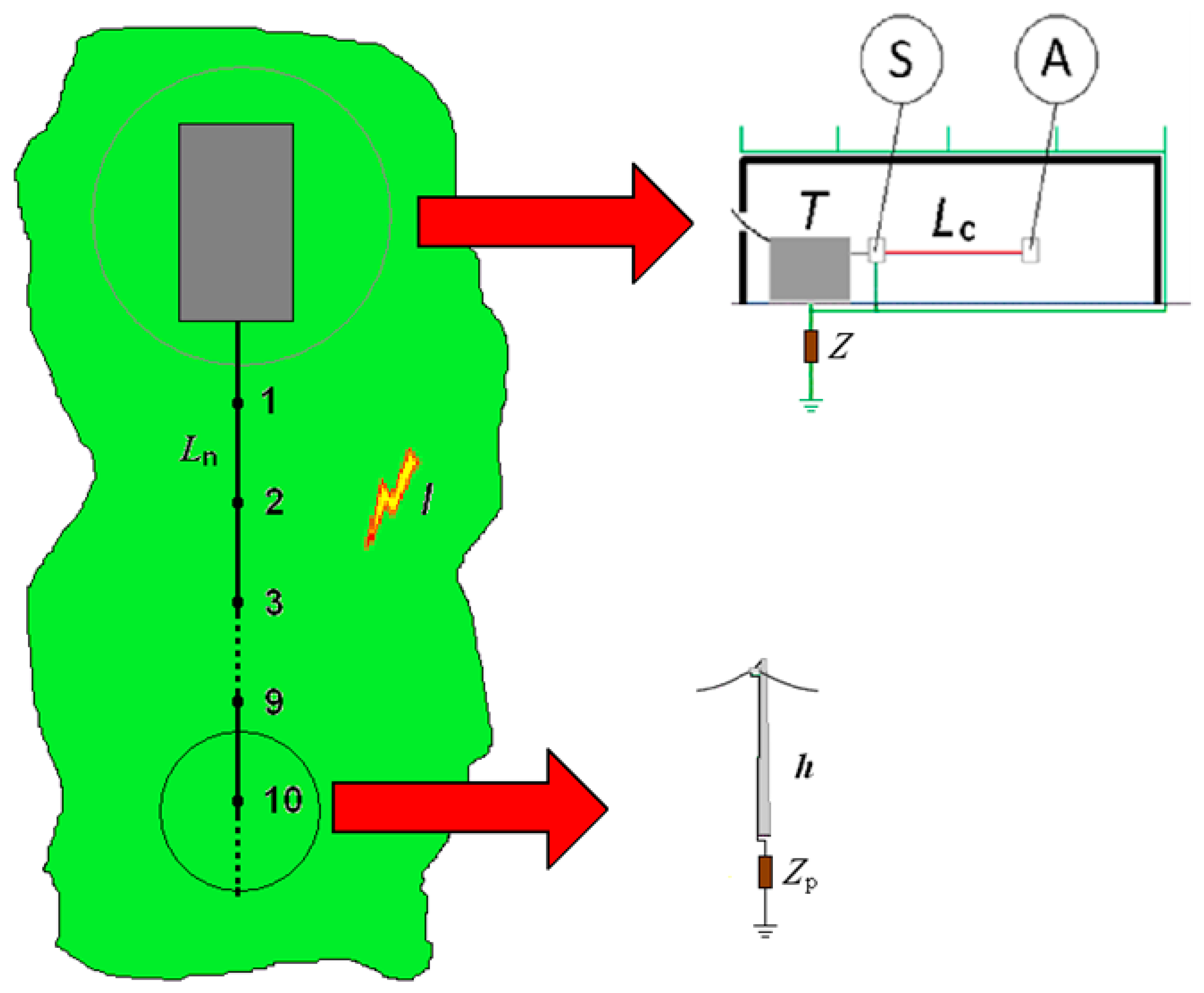
Figure 1. Schematic representation of case study under consideration, where: A—apparatus to be protected; LC—length of circuit between transformer and apparatus; S—main LV panel board; T—Transformer HV/LV; Z—structure conventional earthing impedance; Ln—overhead line span length; 1-2-3-…-9-10—number of poles; I—lightning flash to ground near a line; h—pole height; Zp—poles conventional earthing impedance.
Energies 15 07809 g001
Figure 2. Coefficients a and b as functions of line length L relevant to a normalized (h = 10 m) HV line, for two values of soil resistivity: (a) coefficient a; (b) coefficient b.
Energies 15 07809 g002
Figure 3. Number NI of lightning events per year inducing voltages to ground UH with amplitude higher than the values in abscissa for different values of soil resistivity ρ and line length L, where 1 → L = 1000 m; 2 → L = 100 m; aρ = 100 Ωm; bρ = 500 Ωm.
Energies 15 07809 g003
Figure 4. CT values as function of the length Lc of the LV unshielded circuits.
Energies 15 07809 g004
Figure 5. kCT values in light of number nc of the connected unshielded LV circuits.
Energies 15 07809 g005
Figure 6. Reflection coefficient kr of voltage propagating along the connected LV circuit as function of its length LC.
Energies 15 07809 g006
Figure 7. Trend of the voltage components that build up the voltage UA for LV circuits in conduit.
Energies 15 07809 g007
Figure 8. Trend of the voltage components that build up the voltage UA for LV circuits in multipolar cable.
Energies 15 07809 g008
Figure 9. Frequency of damage NI to apparatus as a function of the length Lc of the LV circuit in conduit.
Energies 15 07809 g009
Figure 10. Frequency of damage NI to apparatus as a function of the distance w between conductors of the LV circuit.
Energies 15 07809 g010
Figure 11. Frequency of damage NI to apparatus as a function of the number nc of connected LV circuits in conduit.
Energies 15 07809 g011
Figure 12. Frequency of damage NI to apparatus as a function of the number nc of connected LV circuits in multipolar cable.
Energies 15 07809 g012
Figure 13. Frequency of damage NI to apparatus as a function of the withstand voltage UW of apparatus for LV circuits in conduit.
Energies 15 07809 g013
Figure 14. Frequency of damage NI to apparatus as a function of the withstand voltage UW of apparatus for LV circuits in multipolar cable.
Energies 15 07809 g014
Publisher’s Note: MDPI stays neutral with regard to jurisdictional claims in published maps and institutional affiliations.