
Accuracy Examination of the SDCM Augmentation System in Aerial Navigation


Abstract
1. Introduction
- –
- BeiDou SBAS (BDSBAS)—a Chinese SBAS positioning system [6],
- –
- European Geostationary Navigation Overlay Service (EGNOS)—the European SBAS positioning system [7],
- –
- GPS Aided Geo Augmented Navigation (GAGAN)—an Indian SBAS positioning system [8],
- –
- Geoscience Australia (SBAS) Test-Bed Project (GATBP)—an Australian SBAS positioning system [9],
- –
- Multi-functional Satellite Augmentation System (MSAS)—a Japanese SBAS positioning system [10],
- –
- Nigerian Satellite Augmentation System (NSAS)—the Nigerian SBAS positioning system [11],
- –
- System for Differential Corrections and Monitoring (SDCM)—Russian SBAS positioning system [12],
- –
- Wide Area Augmentation System (WAAS)—an American SBAS positioning system [13].
- –
- –
- –
- –
- –
- development of an algorithm to integrate SDCM positioning accuracy from two independent SDCM solutions,
- –
- development of an algorithm to reduce position errors and, thus, improve positioning accuracy with respect to a single SDCM solution,
- –
- conducting navigational analyses to confirm the validity of the research methodology developed,
- –
- carrying out navigational studies and analyses for the EGNOS system,
- –
- comparison of accuracy results against ICAO recommendations.
2. Research Method
2.1. Performance of SDCM Accuracy Positioning for Single Receiver—Basic Solution
- –
- for the accuracy parameter [41]:
- –
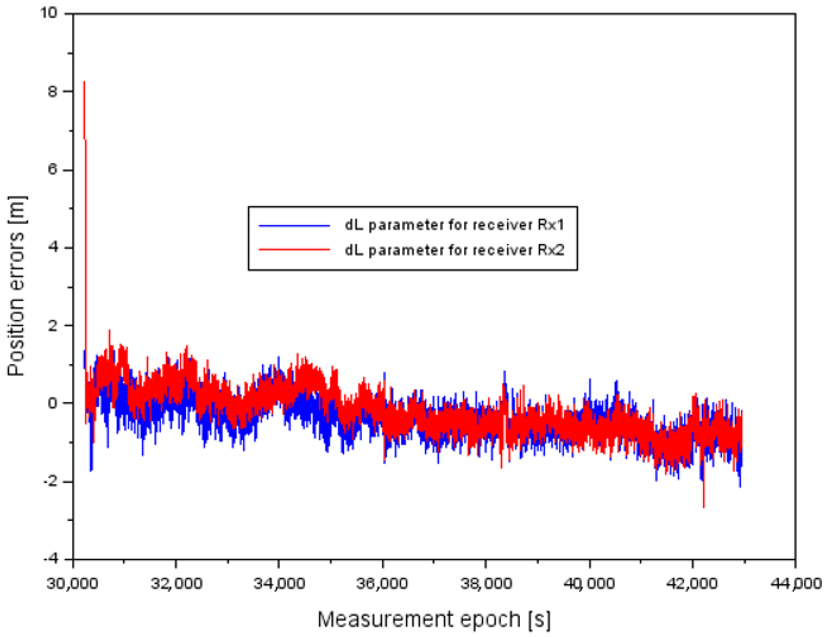
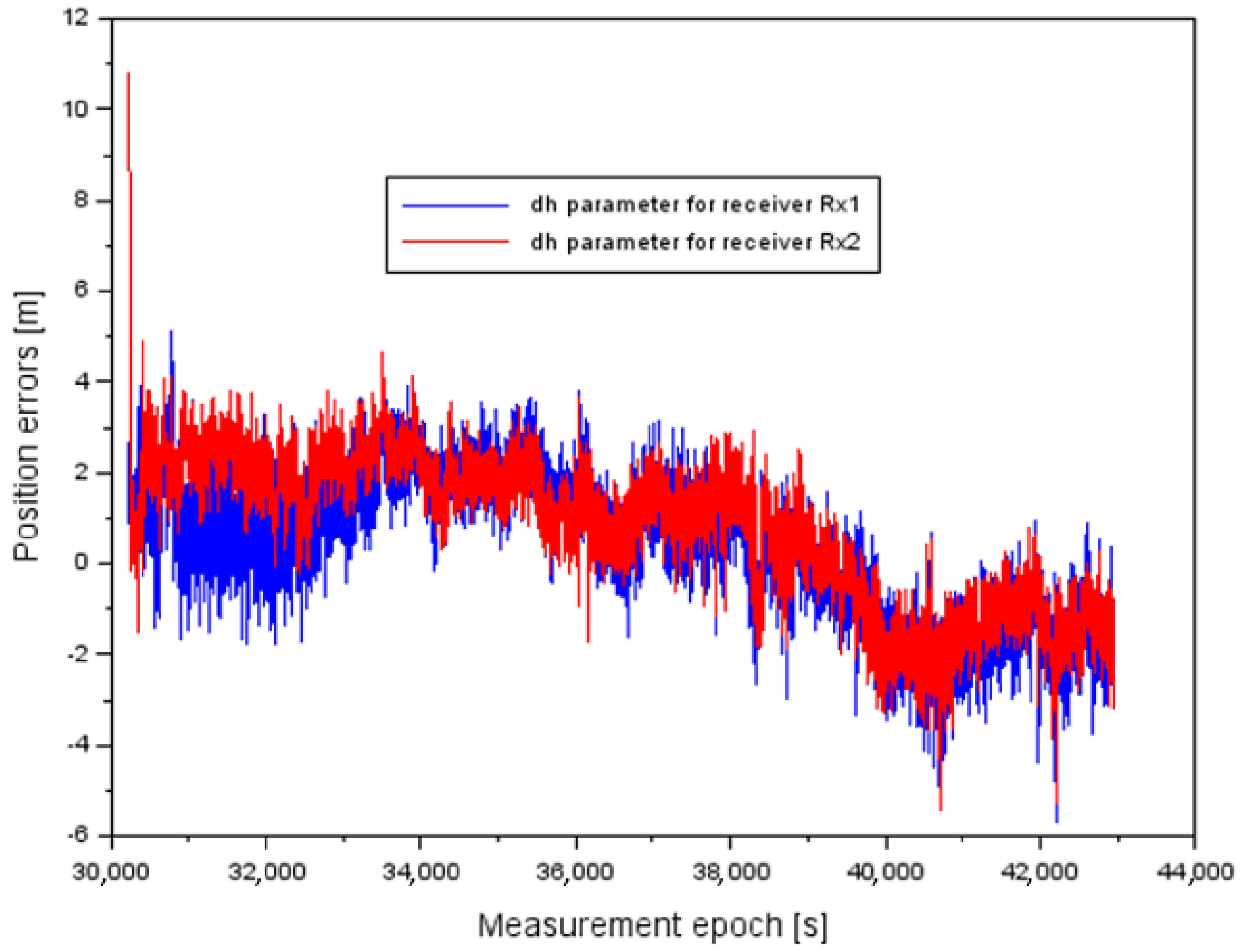
- (dBRx1, dLRx1, dhRx1)—position errors for ellipsoidal coordinates BLh (B—latitude, L—longitude, h—ellipsoidal height) of the aircraft, calculated as the difference between the SDCM navigation solution from a single GNSS receiver and the flight reference position from the RTK-OTF solution [42],
- –
- (BRx1, LRx1, hRx1)—SDCM position navigation solution for a single GNSS receiver,
- –
- (BRTK, LRTK, hRTK)—flight reference position from the RTK-OTF solution,
- –
- —GNSS receiver identification number 1.
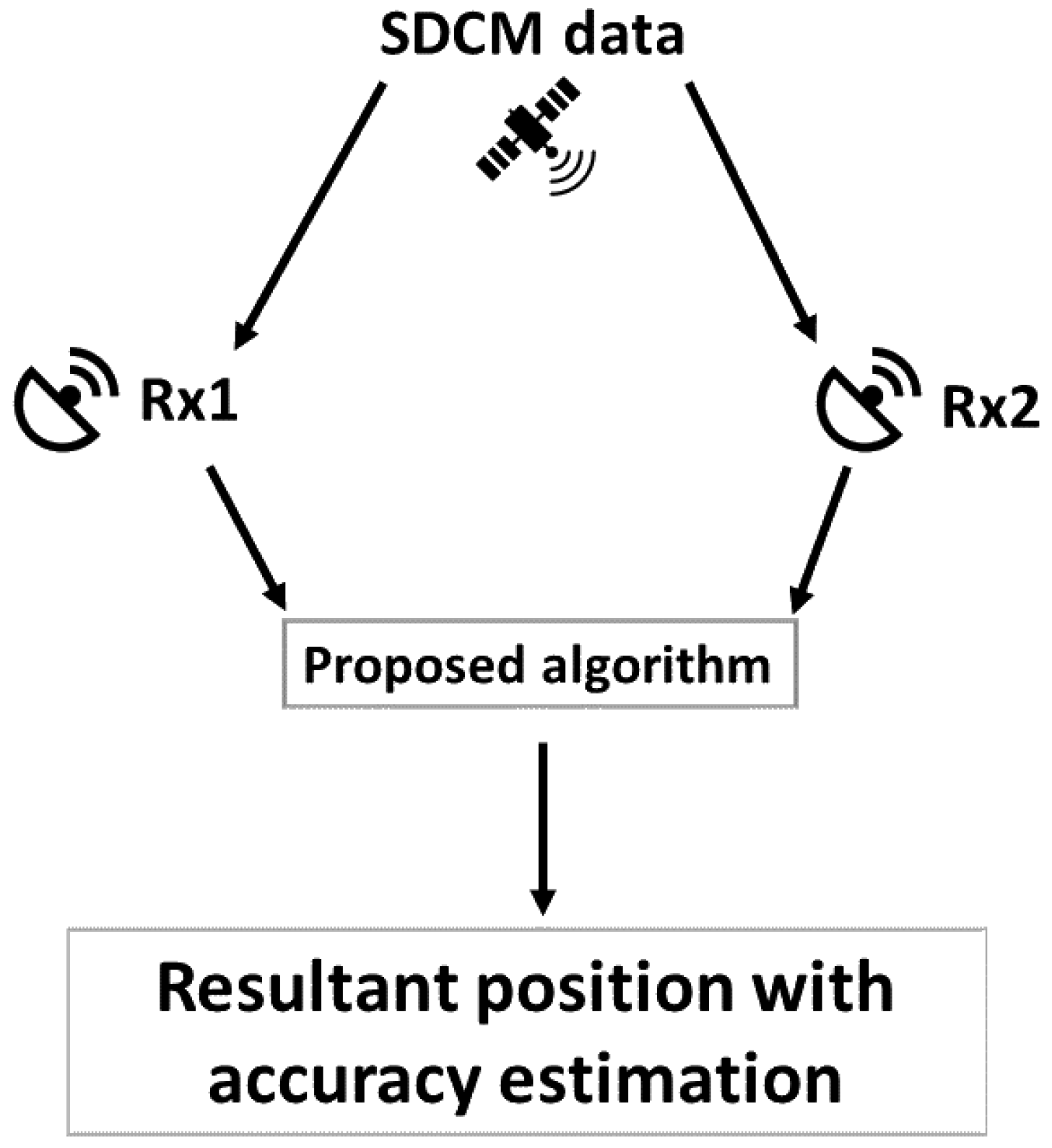
2.2. Performance of SDCM Accuracy Positioning for Dual Receivers—Modified Solution
- –
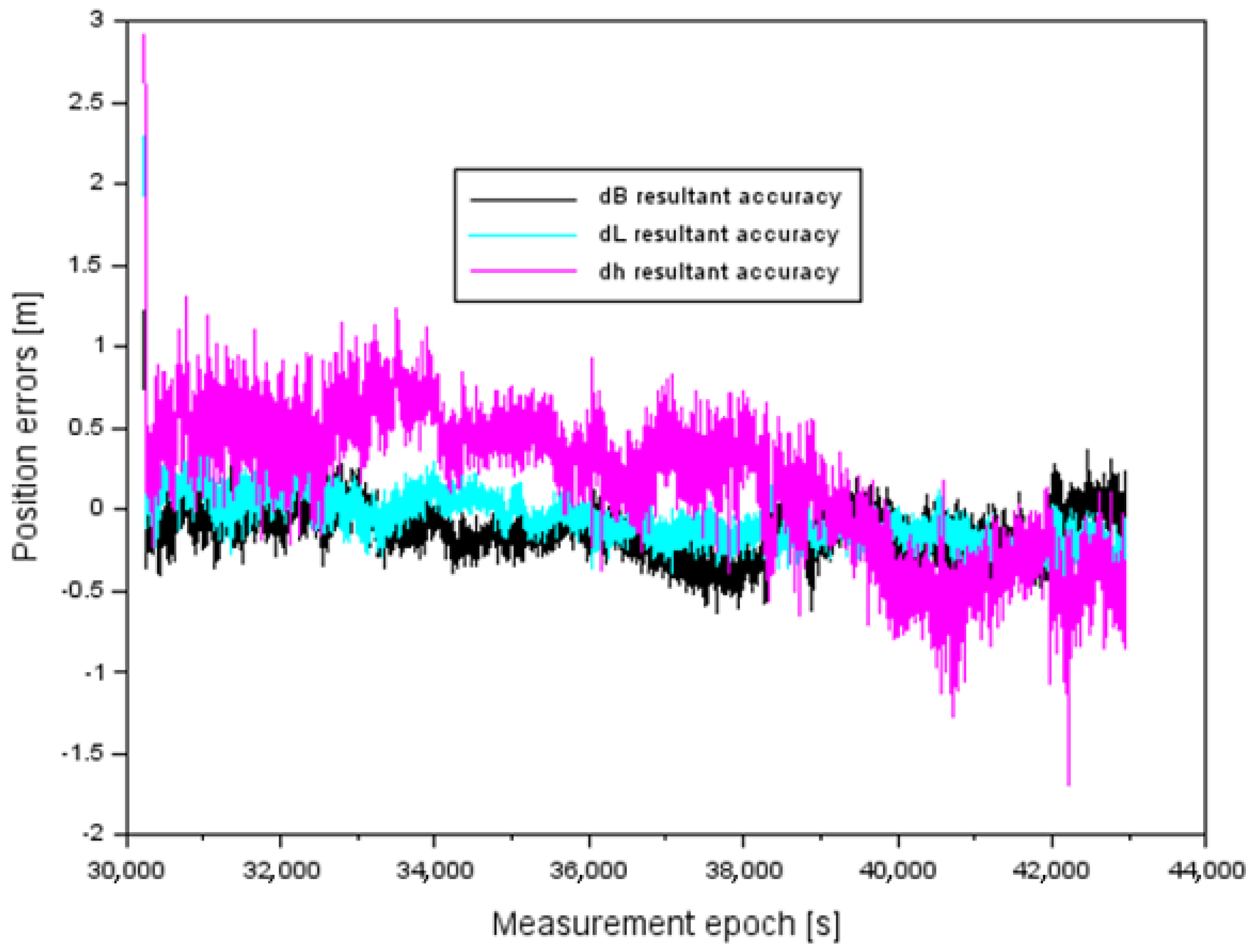
- —resultant accuracy value for a given coordinate component BLh,
- –
- —denotes a given component of B or L or h,
- –
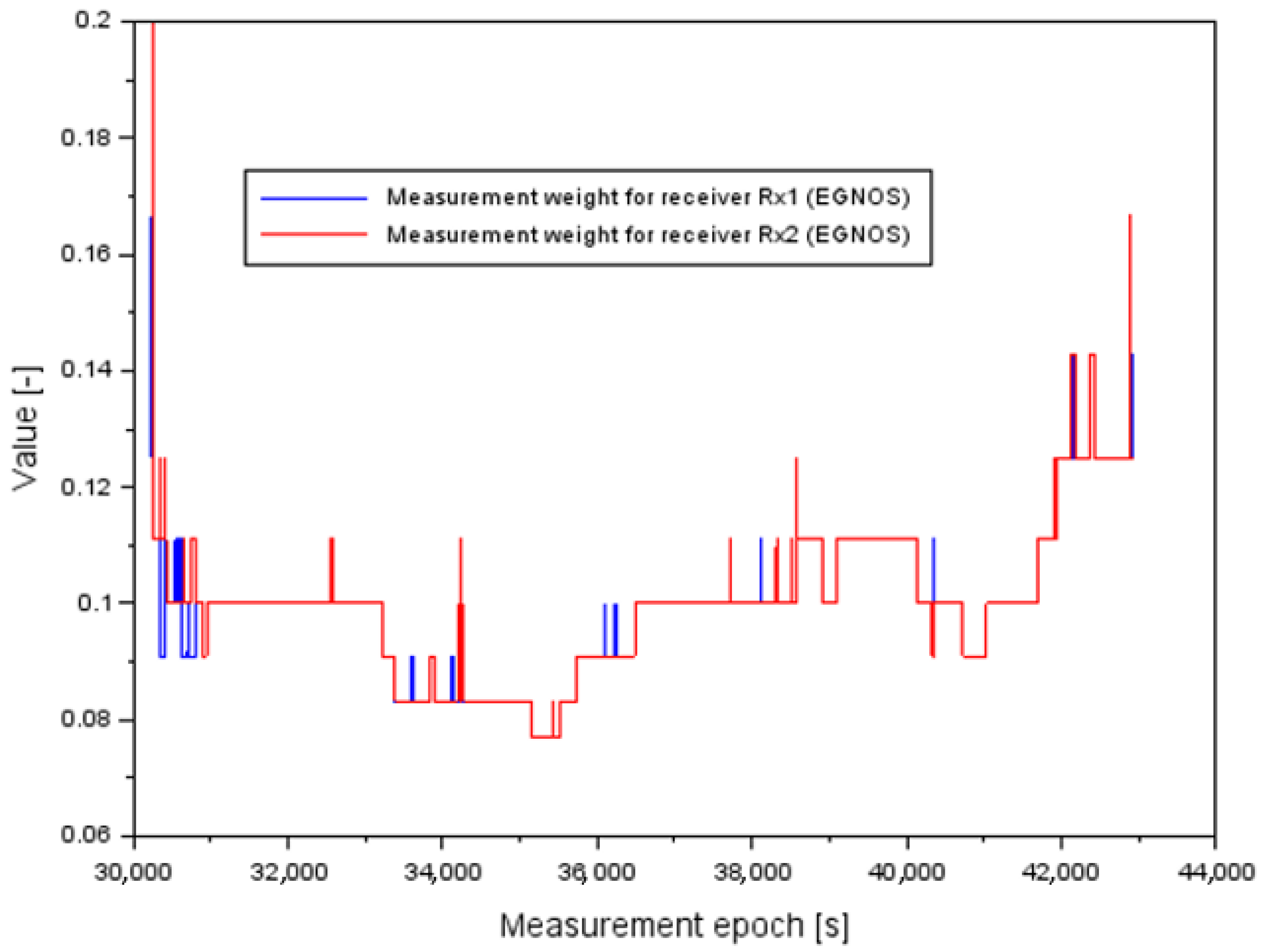
- —linear coefficient of the measurement weight for the receiver ,
- –
- —linear coefficient of the measurement weight for the receiver ,
- –
- —GNSS receiver identification number 2.
- –
- —the determined accuracy value for the receiver from the SDCM navigation solution,
- –
- —the determined accuracy value for the receiver from the SDCM navigation solution.
- –
- —number of tracked GNSS satellites for the receiver from the SDCM navigation solution,
- –
- —number of tracked GNSS satellites for the receiver from the SDCM navigation solution.
- –
- algorithm for resultant accuracy along the B axis:
- –
- algorithm for resultant accuracy along the L axis:
- –
- algorithm for resultant accuracy along the h-axis:
- –
- (—position errors for ellipsoidal coordinates BLh (B—latitude, L—longitude, h—ellipsoidal height) of the aircraft for the receiver Rx2,
- –
- (—resultant values of position errors for the BLh components.
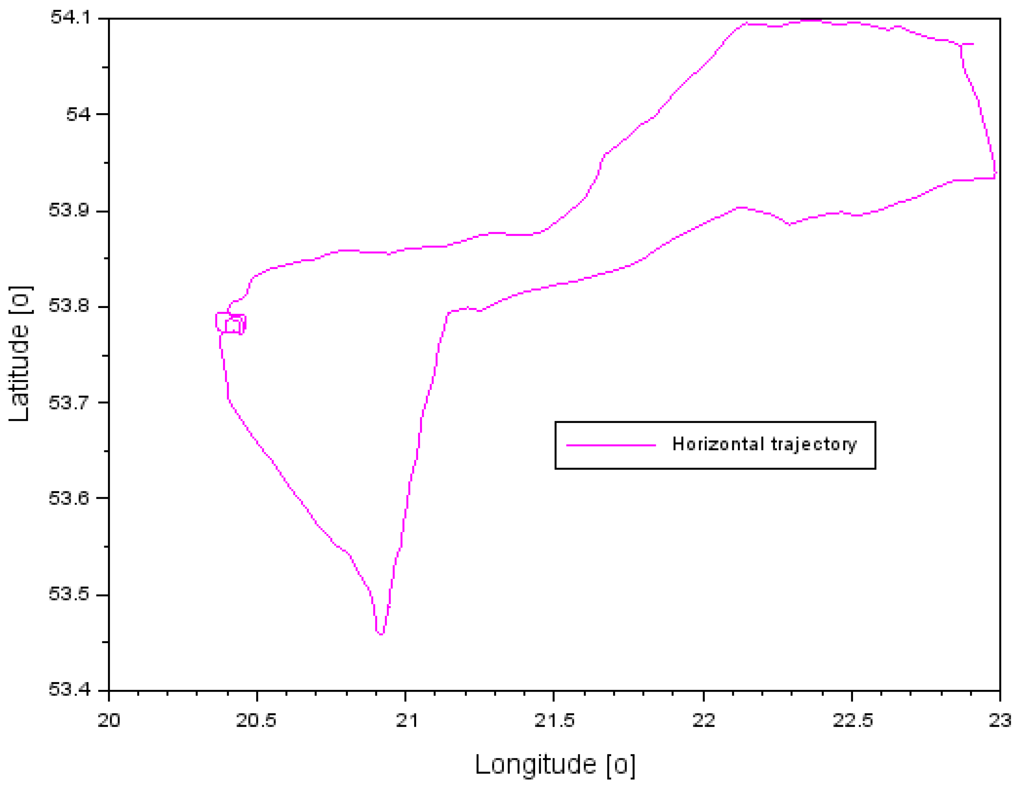
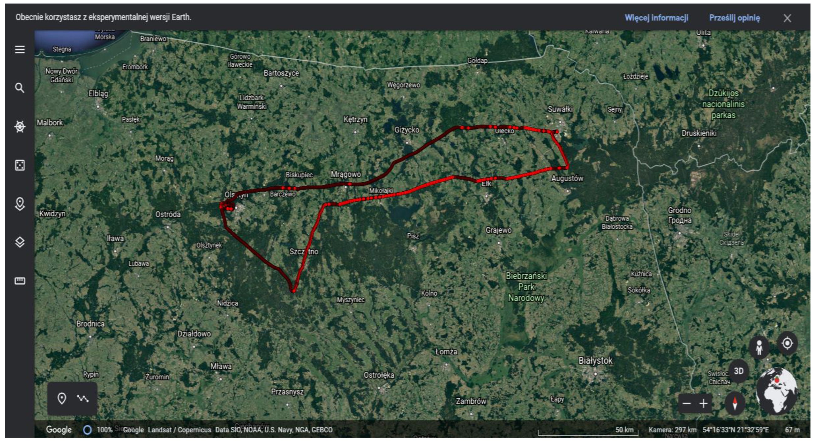
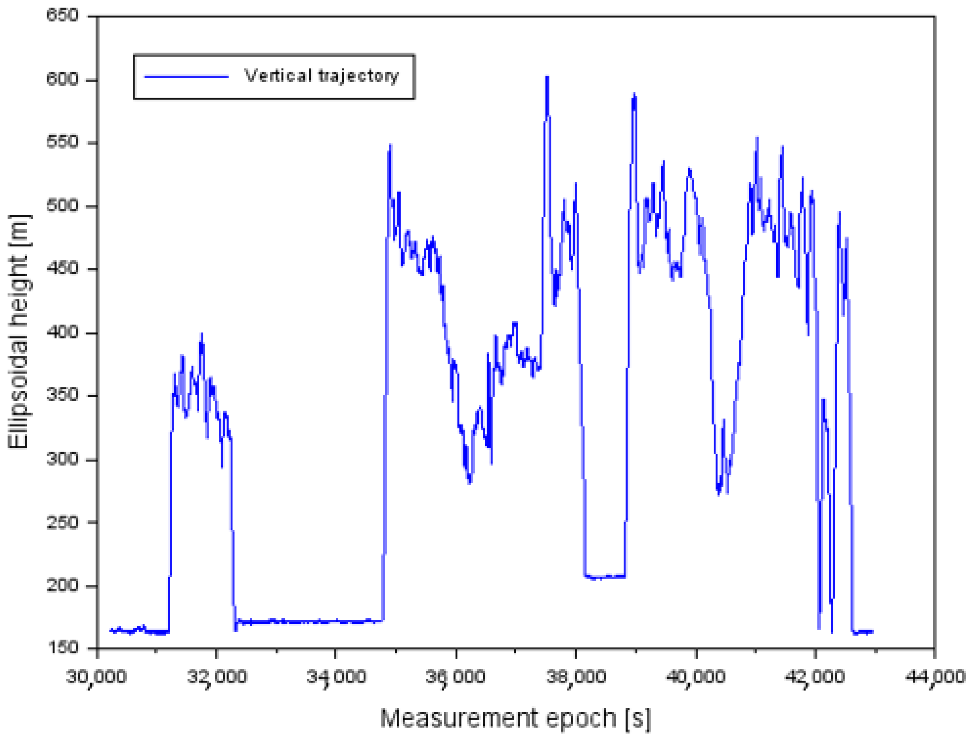
3. Research Test
4. Results
- –
- for the B component:
- –
- for the L component:
- –
- for the h component:
- –
- pdB—percentage improvement in SDCM positioning accuracy for the B component,
- –
- pdL—percentage improvement in SDCM positioning accuracy for the L component,
- –
- —percentage improvement in SDCM positioning accuracy for component h,
- –
- —mean values of the resultant accuracy ,
- –
- —average positioning accuracy values calculated for the receiver ,
- –
- —average positioning accuracy values calculated for the receiver .
5. Discussion
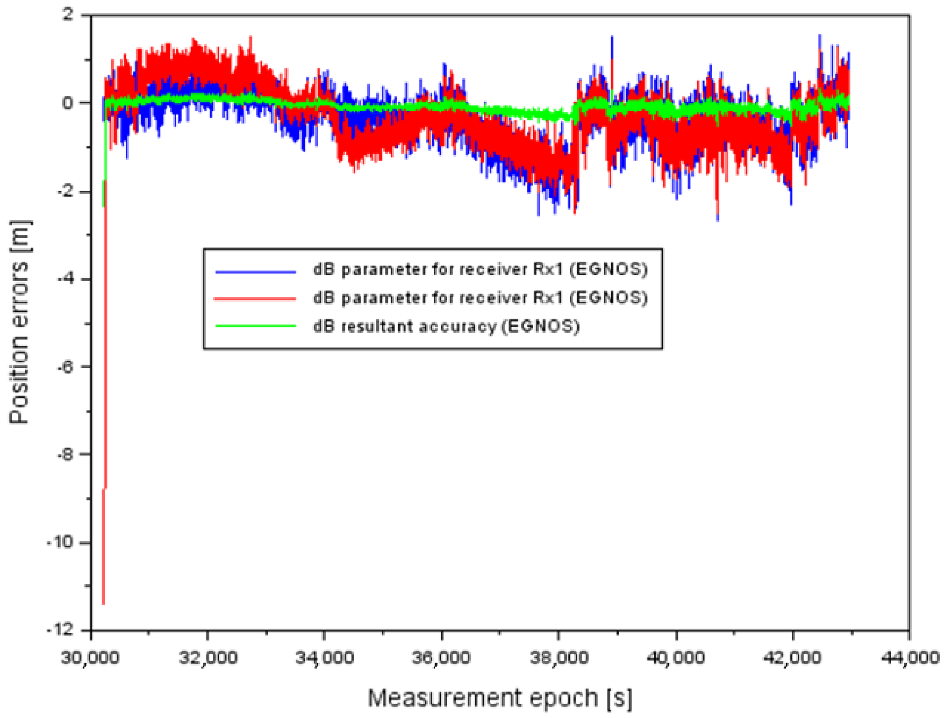
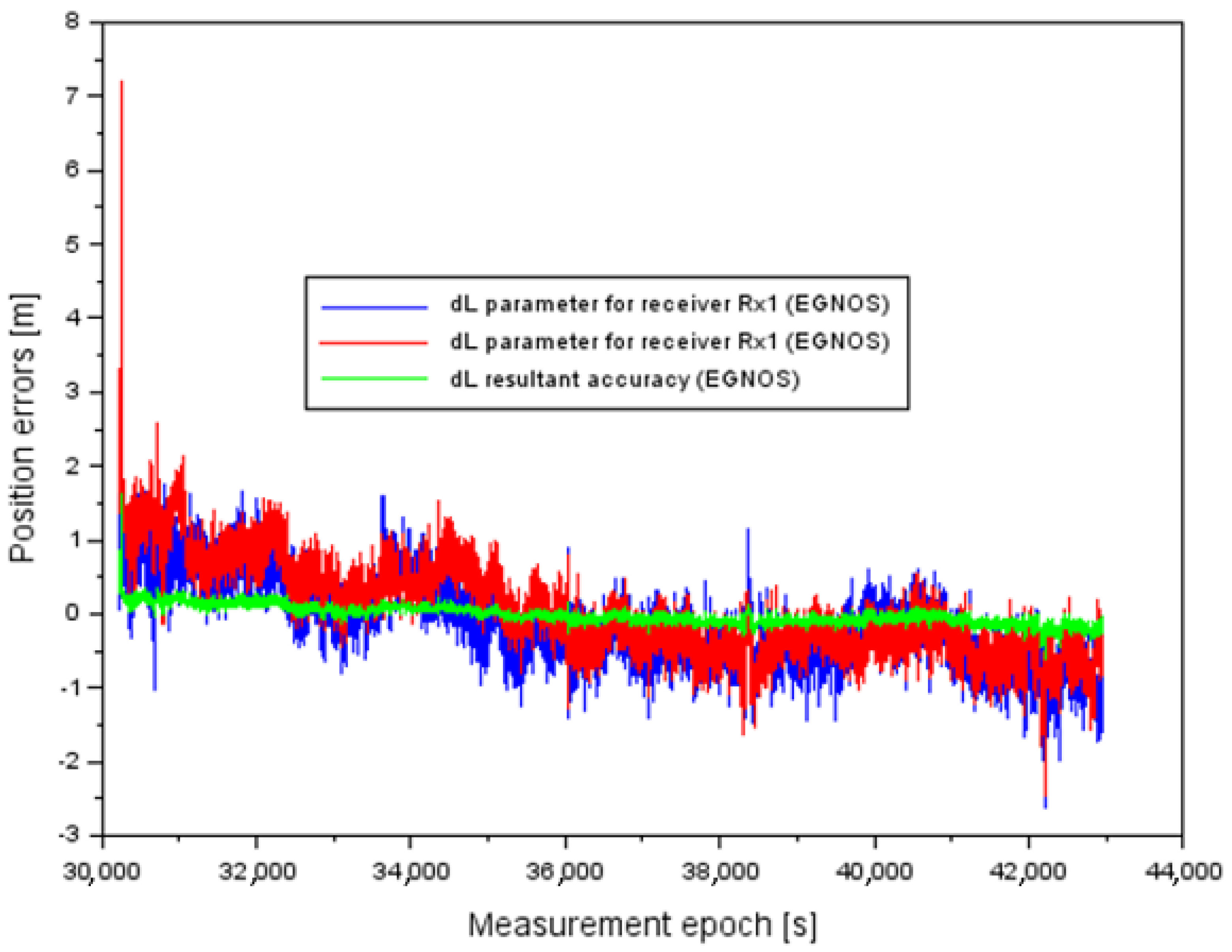
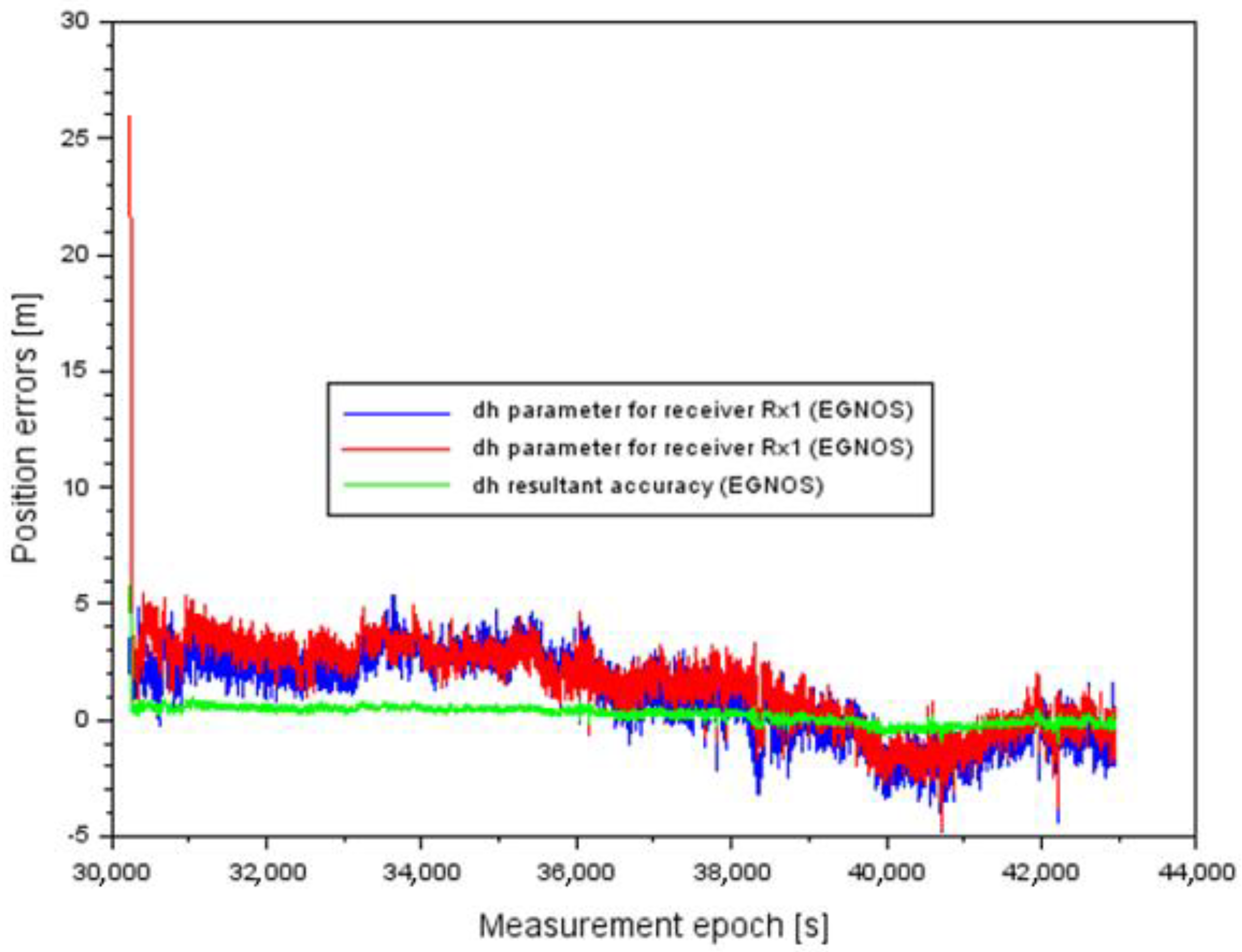
5.1. Implementation of the Research Method for EGNOS System
5.2. Comparison of the Resultant Accuracy of BLh Aircraft Coordinates with Reference to ICAO Recommendations for SBAS System
5.3. Comparison between Research Method and Analysis of Scientific Knowledge
- –
- –
- –
- –
- –
- –
6. Conclusions
Author Contributions
Funding
Institutional Review Board Statement
Informed Consent Statement
Data Availability Statement
Acknowledgments
Conflicts of Interest
References
- Krasuski, K.; Mrozik, M.; Wierzbicki, D.; Ćwiklak, J.; Kozuba, J.; Ciećko, A. Designation of the Quality of EGNOS+SDCM Satellite Positioning in the Approach to Landing Procedure. Appl. Sci. 2022, 12, 1335. [Google Scholar] [CrossRef]
- Jafernik, H.; Krasuski, K.; Michta, J. Assessment of suitability of radionavigation devices used in air. Sci. J. Sil. Univ. Technol. Ser. Transp. 2016, 90, 99–112. [Google Scholar] [CrossRef]
- Ciećko, A.; Bakuła, M.; Grunwald, G.; Ćwiklak, J. Examination of Multi-Receiver GPS/EGNOS Positioning with Kalman Filtering and Validation Based on CORS Stations. Sensors 2020, 20, 2732. [Google Scholar] [CrossRef]
- Specht, M.; Szmagliński, J.; Specht, C.; Koc, W.; Wilk, A.; Czaplewski, K.; Karwowski, K.; Dąbrowski, P.; Chrostowski, P.; Grulkowski, S. Analysis of positioning methods using Global Navigation Satellite Systems (GNSS) in Polish State Railways (PKP). Sci. J. Marit. Univ. Szczec. 2020, 62, 26–35. [Google Scholar] [CrossRef]
- IGS Service. Available online: https://www.igs.org/mgex/constellations/#sbas (accessed on 10 March 2021).
- Li, R.; Zheng, S.; Wang, E.; Chen, J.; Feng, S.; Wang, D.; Dai, L. Advances in BeiDou Navigation Satellite System (BDS) and satellite navigation augmentation technologies. Satell. Navig. 2020, 1, 12. [Google Scholar] [CrossRef]
- Ciećko, A. Analysis of the EGNOS quality parameters during high ionosphere activity. IET Radar Sonar Navig. 2019, 13, 1131–1139. [Google Scholar] [CrossRef]
- Sophan, S.; Phakphisut, W.; Myint, L.M.M.; Supnithi, P. Performances of GAGAN Satellite-Based Augmentation System in Thailand Region. In Proceedings of the 2020 35th International Technical Conference on Circuits/Systems, Computers and Communications (ITC-CSCC), Nagoya, Japan, 3–6 July 2020; pp. 395–399. [Google Scholar]
- El-Mowafy, A.; Wang, K. Second Generation SBAS—Performance Analysis and Bridging Positioning and Integrity Monitoring during SBAS Outages in the Urban Environment. In Proceedings of the 32nd International Technical Meeting of the Satellite Division of The Institute of Navigation (ION GNSS+ 2019), Miami, FL, USA, 16–20 September 2019; pp. 2842–2854. [Google Scholar] [CrossRef]
- Matsunaga, K.; Hoshinoo, K.; Ito, M.; Arai, N.; Imamura, J.; Hashimoto, T.; Kawai, M.; Ikegami, K.; Hiroe, N. MSAS Flight Test and Its Progress. In Proceedings of the 15th International Technical Meeting of the Satellite Division of The Institute of Navigation (ION GPS 2002), Portland, OR, USA, 24–27 September 2002; pp. 1696–1703. [Google Scholar]
- Lawal, S.L.; Chatwin, C.; Li, D. NIGCOMSAT-1R Satellite-Based Augmentation System (SBAS) test bed trial. IJRDO J. Electr. Electron. Eng. 2020, 6, 75–85. [Google Scholar]
- Park, K.W.; Park, J.-I.; Park, C. Efficient Methods of Utilizing Multi-SBAS Corrections in Multi-GNSS Positioning. Sensors 2020, 20, 256. [Google Scholar] [CrossRef]
- Jan, S.-S. Vertical Guidance Performance Analysis of the L1-L5 Dual-Frequency GPS/WAAS User Avionics Sensor. Sensors 2010, 10, 2609–2625. [Google Scholar] [CrossRef]
- Grzegorzewski, M. Navigating an aircraft by means of a position potential in three dimensional space. Ann. Navig. 2005, 9, 111. [Google Scholar]
- Ciećko, A.; Grzegorzewski, M.; Ćwiklak, J.; Oszczak, S.; Jafernik, H. Air navigation in eastern Poland based on EGNOS. In Proceedings of the Aviation Technology, Integration, and Operations Conference (ATIO 2013), Los Angeles, CA, USA, 12–14 August 2013; Red Hook: Curran, NY, USA, 2013; Volume 1, pp. 603–613. ISBN 978-1-62993-206-4. [Google Scholar]
- Grzegorzewski, M.; Ciećko, A.; Oszczak, S.; Popielarczyk, D. Autonomous and EGNOS Positioning Accuracy Determination of Cessna Aircraft on the Edge of EGNOS Coverage. In Proceedings of the 2008 National Technical Meeting of The Institute of Navigation, San Diego, CA, USA, 28–30 January 2008; pp. 407–410. [Google Scholar]
- Grzegorzewski, M.; Światek, A.; Ciećko, A.; Oszczak, S.; Ćwiklak, J. Study of EGNOS safety of life service during the period of solar maximum activity. Artif. Satell. 2012, 47, 137–145. [Google Scholar] [CrossRef]
- Fellner, A. Guidance for the preparation of EGNOS National Market Analysis. Trans. Nav. Int. J. Marine Navig. Safe. Sea Trans. 2018, 12, 349–355. [Google Scholar] [CrossRef]
- Fellner, A.; Fellner, R.; Piechoczek, E. Pre-flight validation of RNAV GNSS approach procedures for EPKT in “EGNOS APV Mielec project”. Sci. J. Sil. Univ. Technol. Ser. Transp. 2016, 90, 37–46. [Google Scholar] [CrossRef]
- Fellner, A.; Jafernik, H. Airborne measurement system during validation of EGNOS/GNSS essential parameters in landing. Rep. Geod. Geoinf. 2014, 96, 27–37. [Google Scholar] [CrossRef][Green Version]
- Ciećko, A.; Grunwald, G. Examination of Autonomous GPS and GPS/EGNOS Integrity and Accuracy for Aeronautical Applications. Period. Polytech. Civ. Eng. 2017, 61, 920–928. [Google Scholar] [CrossRef]
- Ciećko, A.; Grunwald, G.; Ćwiklak, J.; Popielarczyk, D.; Templin, T. EGNOS performance monitoring at newly established GNSS station in Polish Air Force Academy. In Proceedings of the SGEM2016 Conference, Albena, Bulgaria, 30 June–6 July 2016; pp. 239–246. [Google Scholar]
- Grunwald, G.; Bakuła, M.; Ciećko, A. Study of EGNOS accuracy and integrity in eastern Poland. Aeronaut. J. 2016, 1230, 1275–1290. [Google Scholar] [CrossRef]
- Grunwald, G.; Bakuła, M.; Ciećko, A.; Kaźmierczak, R. Examination of GPS/EGNOS integrity in north-eastern Poland. IET Radar Sonar Navig. 2016, 10, 114–121. [Google Scholar] [CrossRef]
- Felski, A.; Nowak, A.; Woźniak, T. Accuracy and Availability of EGNOS—Results of Observations. Artif. Satell. 2011, 46, 111–118. [Google Scholar] [CrossRef]
- Jafernik, H.; Krasuski, K.; Ćwiklak, J. Tests of the EGNOS System for Recovery of Aircraft Position in Civil Aircraft Transport. Rev. Eur. Derecho Naveg. Mar. Aeronáut. 2019, 36, 17–38. [Google Scholar]
- Krasuski, K. Application of the GPS/EGNOS solution for the precise positioning of an aircraft vehicle. Sci. J. Sil. Univ. Technol. Ser. Transp. 2017, 96, 81–93. [Google Scholar] [CrossRef]
- Kozuba, J.; Krasuski, K.; Ćwiklak, J.; Jafernik, H. Aircraft position determination in SBAS system in air transport. In Proceedings of the Engineering for Rural Development 2018, Jelgava, Latvia, 23–25 May 2018; pp. 788–794. [Google Scholar] [CrossRef]
- Januszewski, J. Satellite navigation systems in coastal navigation. Sci. J. Marit. Univ. Szczec. 2012, 29, 45–52. [Google Scholar]
- Januszewski, J. Satellite Navigation Systems in the Transport, Today and in the Future. Arch. Transp. 2010, 12, 175–187. [Google Scholar] [CrossRef]
- Januszewski, J. A Look at the Development of GNSS Capabilities Over the Next 10 Years. TransNav Int. J. Mar. Navig. Saf. Sea Transp. 2011, 5, 73–78. [Google Scholar]
- Januszewski, J. New satellite navigation systems and moderenization of current systems, why and for whom? Sci. J. Marit. Univ. Szczec. 2012, 32, 58–64. [Google Scholar]
- Averin, S.; Dvorkin, V.; Karutin, S.; Kurshin, V.; Urlichich, U.; Klimov, V. Russian System for Differential Correction and Monitoring: A Concept and Results of the First Phase of Development. In Proceedings of the 19th International Technical Meeting of the Satellite Division of the Institute of Navigation (ION GNSS 2006), Fort Worth, TX, USA, 26–29 September 2006; pp. 2103–2110. [Google Scholar]
- Sergey, V.A.; Vjacheslav, V.D.; Sergey, N.K. Russian System for Differential Correction and Monitoring: A Concept, Present Status, and Prospects for Future. In Proceedings of the 20th International Technical Meeting of the Satellite Division of the Institute of Navigation (ION GNSS 2007), Fort Worth, TX, USA, 25–28 September 2007; pp. 3037–3044. [Google Scholar]
- Urlichich, Y.; Subbotin, V.; Stupak, G.; Dvorkin, V.; Povaliaev, A.; Karutin, S. GLONASS Developing Strategy. In Proceedings of the 23rd International Technical Meeting of the Satellite Division of the Institute of Navigation (ION GNSS 2010), Portland, OR, USA, 21–24 September 2010; pp. 1566–1571. [Google Scholar]
- Urlichich, Y.; Subbotin, V.; Stupak, G.; Dvorkin, V.; Povalyaev, A.; Karutin, S. GLONASS Modernization. In Proceedings of the 24th International Technical Meeting of the Satellite Division of the Institute of Navigation (ION GNSS 2011), Portland, OR, USA, 20–23 September 2011; pp. 3125–3128. [Google Scholar]
- Karutin, S. System for Differential Correction and Monitoring Updated. In Proceedings of the 24th International Technical Meeting of the Satellite Division of the Institute of Navigation (ION GNSS 2011), Portland, OR, USA, 20–23 September 2011; pp. 1562–1573. [Google Scholar]
- Karutin, S. SDCM Program Status. In Proceedings of the 25th International Technical Meeting of the Satellite Division of the Institute of Navigation (ION GNSS 2012), Nashville, TN, USA, 17–21 September 2012; pp. 1034–1044. [Google Scholar]
- Karutin, S. SDCM Development Strategy. In Proceedings of the 26th International Technical Meeting of the Satellite Division of the Institute of Navigation (ION GNSS+ 2013), Nashville, TN, USA, 16–20 September 2013; pp. 2361–2372. [Google Scholar]
- Krasuski, K.; Ciećko, A.; Bakuła, M.; Wierzbicki, D. New Strategy for Improving the Accuracy of Aircraft Positioning Based on GPS SPP Solution. Sensors 2020, 20, 4921. [Google Scholar] [CrossRef]
- Specht, C.; Pawelski, J.; Smolarek, L.; Specht, M.; Dabrowski, P. Assessment of the Positioning Accuracy of DGPS and EGNOS Systems in the Bay of Gdansk using Maritime Dynamic Measurements. J. Navig. 2019, 72, 575–587. [Google Scholar] [CrossRef]
- Krasuski, K.; Wierzbicki, D.; Bakuła, M. Improvement of UAV Positioning Performance Based on EGNOS+SDCM Solution. Remote Sens. 2021, 13, 2597. [Google Scholar] [CrossRef]
- Krasuski, K.; Wierzbicki, D. Application of the SBAS/EGNOS Corrections in UAV Positioning. Energies 2021, 14, 739. [Google Scholar] [CrossRef]
- Ibáñez Segura, D.; Rovira Garcia, A.; Alonso, M.T.; Sanz, J.; Juan, J.M.; González Casado, G.; López Martínez, M. EGNOS 1046 Maritime Service Assessment. Sensors 2020, 20, 276. [Google Scholar] [CrossRef]
- Warmia and Mazury Aero Club Website. Available online: http://aeroklub.olsztyn.pl/awm-na-dajtkach/ (accessed on 30 August 2022).
- Google Earth Website. Available online: https://www.google.com/intl/pl/earth/ (accessed on 30 August 2022).
- Specht, C.; Mania, M.; Skóra, M.; Specht, M. Accuracy of the GPS positioning system in the context of increasing the number of satellites in the constellation. Pol. Marit. Res. 2015, 22, 9–14. [Google Scholar] [CrossRef]
- Takasu, T. RTKLIB ver. 2.4.2 Manual, RTKLIB: An Open Source Program. Package for GNSS Positioning. 2013. Available online: http://www.rtklib.com/prog/manual_2.4.2.pdf (accessed on 30 August 2021).
- CNES Service. Available online: ftp://serenad-public.cnes.fr/ (accessed on 30 August 2021).
- Scilab Website. Available online: https://www.scilab.org/ (accessed on 30 August 2021).
- International Civil Aviation Organization. ICAO Standards and Recommended Practices (SARPS), Annex 10 Volume I (Radio Navigation Aids). 2006. Available online: www.ulc.gov.pl/pl/prawo/prawo-mi%C4%99dzynarodowe/206-konwencje (accessed on 30 August 2021).
- Ahad, S.A.; Fahmeen, S.; Sultana, G. Analysis of GPS/GAGAN-based Airborne Receiver Position Accuracy using RAIM Algorithms. In Proceedings of the 2020 IEEE-HYDCON, Hyderabad, India, 11–12 September 2020; pp. 1–5. [Google Scholar] [CrossRef]
- Krasuski, K.; Kobialka, E.; Grzegorzewski, M. Research of Accuracy of the Aircraft Position Using the GPS and EGNOS Systems in Air Transport. Commun. Sci. Lett. Univ. Zilina 2019, 21, 27–34. [Google Scholar] [CrossRef]
- Oliveira, J.; Tiberius, C. Landing: Added Assistance to Pilots on Small Aircraft Provided by EGNOS. In Proceedings of the Conference 2008 IEEE/ION Position, Location and Navigation Symposium, Monterey, CA, USA, 5–8 May 2008; pp. 321–333. [Google Scholar]
- Kim, E.; Peled, U.; Walter, T.; Powell, J.D. A Development of WAAS-Aided Flight Inspection Truth System. In Proceedings of the IEEE/ION PLANS 2006, San Diego, CA, USA, 25–27 April 2006; pp. 61–70. [Google Scholar]
- Fonseca, A.; Azinheira, J.; Soley, S. Contribution to the operational evaluation of EGNOS as an aeronautical navigation system. In Proceedings of the 25th International Congress of the Aeronautical Sciences (ICAS 2006), Hamburg, Germany, 3–8 September 2006; pp. 1–10. [Google Scholar]
- Veerman, H.P.J.; Rosenthal, P. EGNOS Flight Trials, Evaluation of EGNOS Performance and Prospects. In Proceedings of the 2006 National Technical Meeting of the Institute of Navigation, Monterey, CA, USA, 18–20 January 2006; pp. 358–367. [Google Scholar]
- Krasuski, K.; Ciećko, A.; Wierzbicki, D. Accuracy analysis of aircraft positioning using GPS dual receivers in aerial navigation. Sci. J. Sil. Univ. Technol. Ser. Transp. 2022, 115, 23–34. [Google Scholar] [CrossRef]
- Krasuski, K.; Popielarczyk, D.; Ciećko, A.; Ćwiklak, J. A New Strategy for Improving the Accuracy of Aircraft Positioning Using DGPS Technique in Aerial Navigation. Energies 2021, 14, 4431. [Google Scholar] [CrossRef]


| Coordinate | Relation | Improvement [%] |
|---|---|---|
| B | 77 | |
| B | 67 | |
| L | 80 | |
| L | 63 | |
| H | 56 | |
| H | 77 |
| SDCM Solution | ICAO Recommendations | Conclusion |
|---|---|---|
| Resultant accuracy of Latitude is between −0.69 m and +1.22 m. Resultant accuracy of Longitude is between −0.81 m and +2.29 m. | Horizontal accuracy of aircraft equals to ±16 m in SBAS APV-I and SBAS APV-II. | The obtained accuracy for horizontal coordinates did not exceed the ICAO standard. |
| Resultant accuracy of ellipsoidal height is between −1.70 m and +2.92 m. | Vertical accuracy of aircraft equals to ±20 m in SBAS APV-I and ±8 m in SBAS APV-II. | The obtained accuracy for vertical coordinate did not exceed the ICAO standard. |
| EGNOS solution | ICAO recommendations | Conclusion |
| Resultant accuracy of Latitude is between −2.35 m and +0.35 m. Resultant accuracy of Longitude is between −0.64 m and +1.64 m. | Horizontal accuracy of aircraft equals to ±16 m in SBAS APV-I and SBAS APV-II. | The obtained accuracy for horizontal coordinates did not exceed the ICAO standard. |
| Resultant accuracy of ellipsoidal height is between −1.03 m and +5.79 m. | Vertical accuracy of aircraft equals to ±20 m in SBAS APV-I and ±8 m in SBAS APV-II. | The obtained accuracy for vertical coordinate did not exceed the ICAO standard. |
Publisher’s Note: MDPI stays neutral with regard to jurisdictional claims in published maps and institutional affiliations. |
© 2022 by the authors. Licensee MDPI, Basel, Switzerland. This article is an open access article distributed under the terms and conditions of the Creative Commons Attribution (CC BY) license (https://creativecommons.org/licenses/by/4.0/).
Share and Cite
Krasuski, K.; Ciećko, A.; Bakuła, M.; Grunwald, G. Accuracy Examination of the SDCM Augmentation System in Aerial Navigation. Energies 2022, 15, 7776. https://doi.org/10.3390/en15207776
Krasuski K, Ciećko A, Bakuła M, Grunwald G. Accuracy Examination of the SDCM Augmentation System in Aerial Navigation. Energies. 2022; 15(20):7776. https://doi.org/10.3390/en15207776
Chicago/Turabian StyleKrasuski, Kamil, Adam Ciećko, Mieczysław Bakuła, and Grzegorz Grunwald. 2022. "Accuracy Examination of the SDCM Augmentation System in Aerial Navigation" Energies 15, no. 20: 7776. https://doi.org/10.3390/en15207776
APA StyleKrasuski, K., Ciećko, A., Bakuła, M., & Grunwald, G. (2022). Accuracy Examination of the SDCM Augmentation System in Aerial Navigation. Energies, 15(20), 7776. https://doi.org/10.3390/en15207776