Review

Evaluation Methods of Salt Pillar Stability of Salt Cavern Energy Storage

1
State Key Laboratory of Geomechanics and Geotechnical Engineering, Institute of Rock and Soil Mechanics, Chinese Academy of Sciences, Wuhan 430071, China
2
University of Chinese Academy of Sciences, Beijing 100049, China
3
PipeChina West East Gas Pipeline Company, Science & Technology Information Central, Shanghai 200122, China
*
Authors to whom correspondence should be addressed.
Energies 2022, 15(20), 7570; https://doi.org/10.3390/en15207570
Submission received: 9 September 2022 / Revised: 30 September 2022 / Accepted: 10 October 2022 / Published: 13 October 2022
(This article belongs to the Section D: Energy Storage and Application)

Abstract

:
Underground energy storage is essential for the country’s development, and underground salt cavern groups are a productive way to store energy. Safety pillar design is the key to ensuring the safe operation of large salt cavern gas storage groups. Therefore, this paper is based on the salt pillar stability design problem and analyzes three aspects: (1) Three kinds of pillar stability design theories—reliability theory, strain energy theory, and catastrophe theory; (2) Two methods for designing stable pillars—determining pillars through formulas and numerical simulations; (3) The form and influencing factors of salt pillar instability—macro and microform and the main influential factors. From the current research, the major problem is that the design of safety pillars has not been systematic, due to the differences in salt rock in the region, and the engineering of salt pillar design still relies on experience. Finally, the impact of salt pillar width and gas injection and withdrawal on the pillars during the design of the salt cavern is analyzed, and the existing salt pillar theoretical characteristics and development trend are summarized.

1. Introduction

Salt rock has low permeability and good creep performance, it can adapt to the change in storage pressure, and it is soluble in water. These properties make the construction of salt caverns easier and make the salt rock as an ideal medium for energy storage. The development of salt rock began during World War II, and with the development of theory and technology, Western countries have regarded salt rock as an important energy storage medium. In 1915, the first underground salt cavern gas storage was built and put into operation in Canada [1]. Subsequently, Western countries began to build more caverns.
China is rich in underground salt rock sources and has a wide range of distribution of such deposits. There are large salt rock formations in Sichuan, Yunnan, Jiangxi, Hubei, and Shandong. China built the first domestic salt cavern gas storage in Jiangsu Jintan, in 2005. So far, more than ten underground gas salt caverns have been built. With the country’s emphasis on underground energy storage and the implementation of the carbon neutrality mission, the 14th Five-Year Plan period will usher in the climax of the development and utilization of salt rock gas storage in China. It is estimated that there will be 3 × 10 10   m 3 working gas storage construction in the next fifteen years, and the goal is to form a regionally coordinated underground gas storage group in the central and eastern regions of China [2].
Building large-scale salt cavern underground storage groups is an essential way of developing the salt rock. The overall stability of the storage groups needs to consider the size of the storage space and the salt pillar width. Inadequate pillar width may lead to serious accidents. For instance, the instability of multiple salt pillars caused partial surface subsidence during the operation of the salt cavern storage group in the Hengelo area of The Netherlands [3]. Therefore, optimizing reasonable storage spacing is essential for the storage group construction. If the spacing is too small, it will cause interaction between caverns and lead to instability [4].Therefore, finding a stable critical spacing is the key to optimization of pillar design [5], and the design of critical spacing needs to consider a variety of factors, such as operating parameters, creep characteristics, pillar strength, mining depth, and pillar size. At the same time, salt pillar design needs to consider complicated working conditions [6]. Therefore, it is urgent to study salt pillar design, develop salt pillar design theories, and determine the design method of salt pillar engineering. These will ensure the safe operation of salt cavern gas storage and be of great significance in improving the utilization of underground salt resources in China. A salt pillar is shown in Figure 1.
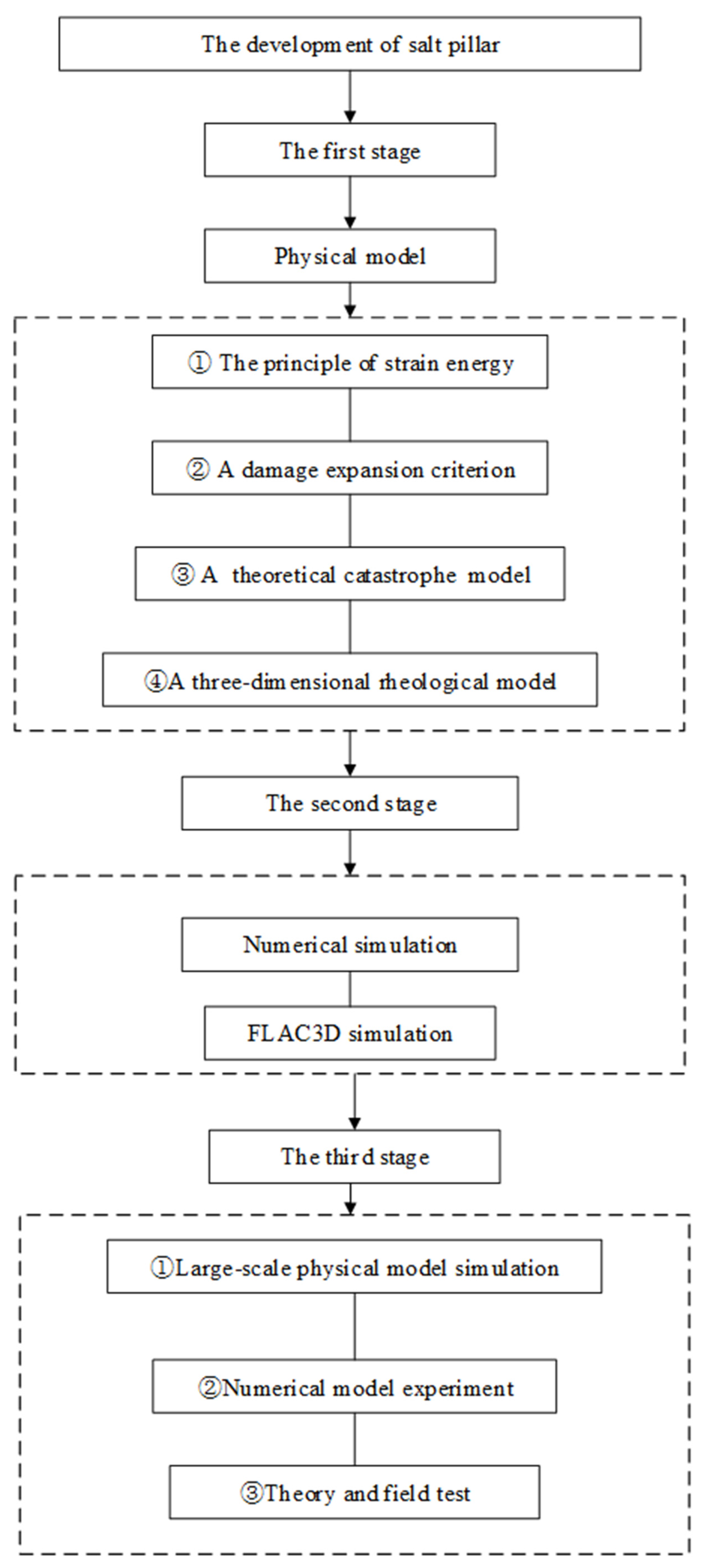
Therefore, it is necessary to analyze salt pillars. Scholars have analyzed salt pillar strength, stability, instability mechanisms, creep characteristics, pillar width, depth, and internal pressure. From the perspective of the development level, the studies can be divided into three stages:
  • The first stage: the phase of the investigation of basic mechanical properties of the pillar and the development and application of models. During this stage, one mainly builds physical models for experimental simulation, and then explores the mechanics and other related properties of the salt pillar;
  • The second stage: the phase of combining computer simulation and traditional analysis. This stage involves the analysis of the numerical model and the mechanical parameters to ensure the stability of the pillars between salt caverns;
  • The third stage: the comprehensive research phase of calculation analysis and large-scale experiments. This stage involves the comprehensive analysis of the adequate width and stability of the pillar through the numerical analyses combined with the large-scale physical model.
In the first stage, scholars established basic theories through experiments to study the mechanical properties of the pillars. Thailand scholar Prapasiri established the principle of strain energy by analyzing the strength of a salt pillar over time and predicted the change in the salt pillar strength over time [7]. Based on the experimental analysis of layered salt rock, DeVries proposed a damage expansion criterion for salt rock from triaxial compression to triaxial tension [8]. Ren established a catastrophic theoretical model of pillar stability and explained the sudden jump and energy release mechanism of pillar instability through a simplified mechanical model [9]. Zhang put forward the conclusion that the pillar width should be greater than 1.5 times the maximum diameter of the salt cavern by evaluating a similar model of layered salt rock underground storage caverns [10]. Zhang established a three-dimensional rheological model test and evaluated the influence of cavern spacing and pressure difference on the deformation of the surrounding rock [11]. In the construction of the pillar theory and basic models, combining the relevant mathematical principles and mechanical analysis methods to carry out salt pillar design, constructing pillar models, and analyzing the pillar stability are research hotspots. Wang proposed a theoretical formula of the limit width of the pillar through the limit balance method and safety factor approach [12]. Liu analyzed the reliability of the salt pillar based on the mass mechanical parameters and external loads and regarded this as a criterion for evaluating the stability of the pillar [13]. Liu continued to analyze the stable state of the pillar by combining two indicators: reliability analysis and the point safety factor method [14]. Bekendam studied the impact of pillar creep on ground settlement through the subsidence rate map and confirmed that pillar deformation can cause subsidence [15].
In the second stage, the development of numerical simulation provides a new way to study pillars, and scholars begin to use the numerical simulation software to explore the pillar design theory and pillar stability mechanism. Mo used FLAC3D to simulate the influence of pillar width on the stability of gas storage caverns [16]. Liu considered the influence of different gas storage cavern spacings on the damage expansion area, determined that the salt cavern spacing should be twice the diameter of the salt caverns through combining the Mohr–Coulomb criterion and the damage expansion criterion [17]. Wang studied the influence of pillar width, internal pressure, depth, and creep time on pillars’ stresses and pillar defamation through FlAC3D [18]. Wu established a gas storage stability rating standard and a pillar safety stability criterion through numerical calculation [19]. Wang studied the effects of depth, pressure, creep, pillar width, etc. on pillar stability by establishing a nonlinear catastrophic cusp displacement model [20]. Wu investigated the distribution of the vertical stress in a salt pillar through the two ideal ellipsoids numerical calculation model [21]. Wang proposed a dynamic elastoplastic model using the FISH language of FLAC3D. He found that the plastic zone spreads along the salt pillar [22]. Zhao established a stable failure function of the salt cavern pillar based on the Mohr–Coulomb criterion. He also evaluated the safety of the salt pillar by the Monte Carlo sampling method [23]. Lukas studied the influence of bolt support on the stability of a pillar through numerical simulation using the finite element method [24].
In the third stage, the research of pillars is the comprehensive development direction of large-scale physical model simulation, numerical modeling, theory and field tests. The stability design theory of pillars is gradually developing systematically. Li analyzed the stability and failure mechanism of salt pillars using mechanical experiments, numerical simulation, and theoretical analysis [25]. Fu optimized the safety pillar parameters through actual engineering analysis of the Huangchang salt cavern in the Jianghan Basin [26]. Song designed an orthogonal test of pillar stability and indicated that the pillar width is a key factor affecting pillar stability [27]. Zhang proved the ability to transform salt cavern storage into an oil storage cavern by analyzing the diameter ratio of the salt cavern pillars [28]. Zhang analyzed the stability of a salt cavern through numerical simulation and a physical model [3]. Baryakh et al. proposed an experimental theoretical method for the prediction of the remaining life of the salt pillar based on the compensation method [29]. Van Sambeek proposed a pillar design equation based on plane stress and axisymmetric angle. He verified it through numerical simulation [30]. Yang proposed a large-scale underground gas storage-intensive design plan, designed the width of the pillar between adjacent salt caverns and adjacent salt cavern groups, and established a three-dimensional digital geological model by using the characteristics of the Jiangsu Jintan salt caverns to verify the design feasibility [31]. Stautmeister provided guidance and suggestions for the design of salt cavern shape and pillar width based on numerical simulations and experiments [32].
A comprehensive analysis of the development stage of salt pillars followed. During the three stages, the theoretical design of coal pillars is becoming mature. Scholars have conducted many kinds of research on the instability of coal pillars. Additionally, they can utilize related engineering and technology to design salt pillars. However, there are still some differences in properties between the salt pillars and coal pillars. Regarding the salt pillars, most scholars analyze the stability of the salt cavern and concentrate on analyzing whether the pillar design is reasonable. However, due to the invisibility of underground salt pillars, the analysis result is pessimistic. It is urgent to improve the design and stability evaluation of salt cavern pillars. This paper is based on the analysis of the three stages of salt cavern pillar development: (1) (Basic theoretical research + Model research) → (2) (Basic theoretical research + Model research + Numerical analysis) → (3) (Basic theoretical research + Large-scale model research + Numerical analysis). The salt pillar research flow is shown in Figure 2.

2. Analysis of Destabilization Damage of Salt Pillar under the Action of Ground Stress

2.1. Macroscopic Manifestations of Salt Pillar Instability

Different depths of salt caverns produce different magnitudes of forces and different forms of destabilization of the salt pillar. Additionally, the manifestation of the destabilization of the salt pillar is different in macroscopic and microscopic forms. The macroscopic destabilization of the salt pillar is a change in the form of rupture, and the rupture microscopically is a process of rupture nucleation.
Salt pillars appear after the salt caverns are formed, and the stress on the pillars increases due to the redistribution of ground stress. When the stress in a salt pillar exceeds a certain limit, the pillar will be destroyed. According to the different mechanical properties of the pillar, the changes in the depth and geological conditions, and the action of the three types of stress, viz., ground stress, gas pressure in the cavern, and brine pressure, a pillar may remain stable or not. The salt pillars may suffer different forms of damage. When the two caverns are injected with gas at the same time and the gas storage group is shallow, the ground pressure and brine pressure in the cavern cause the horizontal ground stress to be higher than the vertical pressure, and the salt pillar will be tensioned [25], as shown in Figure 3a.
When the pressure in the two caverns is unequal, the pillar may undergo shear failure during the gas injection and production process, as shown in Figure 3b [25]. Wang et al. [22] show that increasing the gas pressure in the storage makes the salt pillar sheared. The minimum principal stress increases, and the maximum principal stress remains unchanged, which reduces the shear stress in the pillar.
When the two caverns produce gas at the same time, the pressure in the cavern and the brine pressure are reduced, especially in a cavern group located in a deeper formation. Then, vertical ground stress is higher than horizontal stress. Additionally, the salt pillar will expand and destruct, as shown in Figure 3c [25].
In addition to these three types of damage, there is slip and collapse damage along geological structure surfaces [33] and other damage modes in complex geological environments, as shown in Figure 3d,e.
In the actual process, the form of damage of the salt pillar is often not one, but a combination of several types. Specifically, when tensile damage occurs, shear damage and shear crack may also occur, while slip damage may also occur during shear damage, and shear damage may also occur when expansion damage occurs. In summary, the damage form of the salt pillar is not only limited to one of the above-mentioned damage forms, but in the actual engineering context, most of them are the coupling reaction of various damage forms.
The destruction mechanism of salt rock pillars is the same as that of other rock. Its microscopic nature is the crack propagation. The specific explanation is that salt rock is a rock material with pores, and there are a large number of microscopic defects distributed inside it. When it bears a certain load, it will produce a large number of mesoscopic cracks. Along with the continuous increase in the load, the cracks continue to increase until the cracks penetrate the salt rock. The essence of pillar failure is the evolution of internal cracks under load. Under the condition of increasing load, the interaction between cracks leads to the generation of local weakened areas and leads to the macroscopic failure of the pillar.
If the stability of the salt pillar is destroyed, it may cause huge difficulties. The surface will subside, and the gas will leak, and the brine will leak. Declining ground surface and building damage can cause irreversible damage to the entire gas storage, as shown in Figure 4.

2.2. Microscopic Manifestations of Salt Pillar Instability

In addition, analyzing from a detailed point of view, the destabilization of the salt pillar occurs through the process of microcracking development, nucleation, etc. The microstructure failure of the salt pillar is considered from the molecular scale, that is, analyzing the rupture process from the thermal defect generation. Considering instability from the quantum perspective, the direct cause of microscopic thermal defects in salt pillars is the disorder in atomic space, and the development of such thermal defects is connected with the laws of thermodynamics. When a crystal deteriorates from order to disorder, the defects in it grows, and this deterioration is related to temperature and pressure. When the defects are all generated, it means the end of the life of the salt pillar. The life span of the salt pillar has been given by Zhurkov [34].
t = t 0 exp ( Δ ε 1 γ F k T )
The t represents the period of self-excited vibration of atoms in a solid, Δ ε 1 represents activation energy, F represents external force, and γ represents the parameters related to the structure or the way the forces are applied.
The macroscopic process of pillar failure is that the original layered salt rock bears the load of the overlying strata before the cavern is dissolved. At that time, the original layered salt rock is in a state of a three-way force balance. When the cavern is mined out, the original continuous salt rock interlayer is interrupted, the cavern area no longer bears the load of the overlying strata, and the load of the overlying strata is transferred to the pillar.
A lot of factors affect the instability of a salt pillar. The stability of the salt pillar is mainly related to the lithology and strength of the pillar itself, its geometric size, the goaf rate of the gas in the cavern, its creep characteristics, the pillar depth, and the load of the overlying strata, etc.
Pillars with different strengths and rigidity should adopt different retention methods and principles. Among the geometric dimensions of the pillar, the main factors are the width and the height of the pillar.
Regarding the goaf rate, it is necessary to not be excessive in the process of gas injection and withdrawal, so as to ensure the service year of the salt pillar. The strain rate and long-term strength of the salt rock pillar during its creep change with the changes in the confining pressure and temperature [35]. Therefore, it is essential to understand the influence on the pillar of confining pressure and temperature. We need to design different pillar widths under different depths and overlying strata to ensure the stability of the salt pillar.
Scholars usually use the orthogonal experiment method to analyze the factors affecting the stability of the pillars [27]. They also calculate the stability safety factor by designing an orthogonal experiment to determine the sensitivity of each factor. The orthogonal experiment has the characteristics of fewer experiment times and balanced analysis. The orthogonal experiment results of the salt pillar can analyze the changes in its safety factor along with several factors and sort the indicators of the pillar stability factors. The stability evaluation of the pillar is carried out by constructing a safety factor formula.

3. Basic Theory of Salt Pillar and Design Methods

3.1. Basic Theory of Salt Pillar

From the perspective of pillar theory, the use of formulas and numerical analysis to build pillar stability design criteria is the basis for pillar design development. Analyzing the influencing factors of the salt pillar instability and the macro–micro form of the salt pillar instability is essential. Examples of approaches are shown in Table 1.
The stability of pillars in gas storage is a manifestation of safe pillars. Because of the complex conditions of salt rock, there may be differences between the pillar’s characteristics and theory. Therefore, the pillar design should improve based on the original pillar theory to make sure to obtain a true situation that conforms to the salt rock and its interlayers, and then carry out the engineering design. At present, there are three main theories for pillar stability design.

3.1.1. The Mohr–Coulomb Criterion of Salt Pillar

The first design theory is based on the Mohr–Coulomb criterion. At present, most of the analysis of safety pillar stability is qualitative analysis. Liu [13] analyzes the value of pillar strength and pillar stress to judge the stability of the pillar based on the structural limit state function.
Q P = Q r · B / H σ P = σ V / ( 1 η )
where the Q r represents the rock mass strength; B / H represents the width to height ratio of the pillar; σ V represents rock mass gravity; and η represents the recovery rate of salt rock. Additionally, the ultimate limit state equation is as follows:
Z = R S = Q r B / H σ V / ( 1 η )
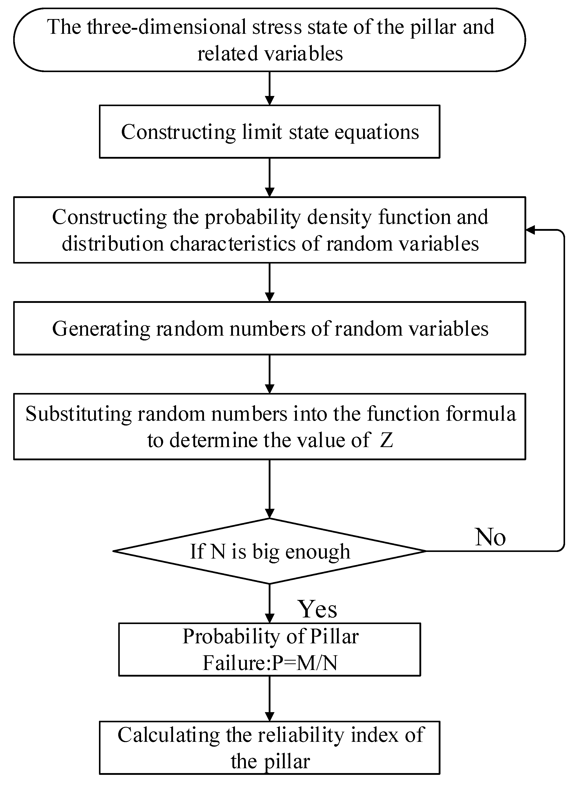
The stable state of the pillar by judging the Z value: if Z > 0, the salt pillar is stable; if Z < 0, the salt pillar is unstable. Then, based on this research idea combined with the changes in salt cavern pillars, Zhao [23] proposed a method for judging the stability of salt cavern pillars based on the Mohr–Coulomb criterion. This method is based on the probability algorithm to determine the failure mode of the pillar. The specific flow chart is shown in Figure 5.
The reliability method provides a new idea for the stability analysis based on the Mohr–Coulomb criterion. Additionally, it is applied in actual underground engineering. Though it adopts a quantitative analysis method, the randomness value N must be large enough, and the standard for defining the N value is still open to question.

3.1.2. The Strain Energy Theory of Salt Pillar

Under a certain confining pressure, triaxial compression experiments on salt samples were conducted by controlling the strain rate. The strain rate range was set from 10−7 s−1 to 10−4 s−1. It was found that as the strain rate increases, the strength and modulus of elasticity show exponential growth. Revising the creep law of salt rock through the experimental results, establishing the strain–time curve of the salt pillar under the different depths and different extraction ratios, and then establishing the strength criterion of the salt pillar using the strain energy theory, and combining the strength criterion with the strain–time curve.
In the strain energy theory, the time-varying effect of salt was an essential factor affecting the stability of the pillar. The function of stress, strain, and time can be adjusted through the creep model, and the selected parameters are calibrated according to the experimental data. The strength criterion based on the principle of strain energy is more applicable than the traditional strength criterion. Because the strength of the salt rock and the strain during expansion can be considered, and the distortion strain energy of the pillar during dilatancy and failure can be determined. Although it is only to a certain extent. The above theory ignores the shape and end effect of the pillar. Therefore, this theory needs to be further developed for the design of pillar strength in a specific environment.

3.1.3. The Catastrophe Theory of Salt Pillar

By building a mechanical model, using catastrophe theory to study the critical conditions of pillar instability and the energy release mechanism during the catastrophe. The salt pillar and salt roof are important structures for the stability of the salt cavern of the gas storage [36], so it is necessary to analyze the stability of the pillar and roof. According to the catastrophe theory, the salt pillars can be assumed to be symmetrically distributed, and the roof rock layer can be simplified as a beam structure. Therefore, regarding the salt pillar as a one-dimensional pillar and the beams as hard roofs.
The supporting force of the pillar on the roof can be regarded as a concentrated force, and the weight of the overlying rock layer can be a uniform force. This theoretical hypothesis regards the constitutive relationship of the pillar as a non-linear relationship with softening properties:
g ( u ) = λ u e u / u 0
In the equation, the u represents the pillar compression, λ represents initial stiffness of pillar, and u 0 represents deformation   vlaue   corresponding   to   peak   load .
Under the assumption, the equation of the balance surface and carried out corresponding expansion was established. Finally, the expression of the sudden change in the system was obtained:
π 4 E I 4 L 3 λ e 2
where E is the elasticity modulus; I represents beam elements inertia moment; and L   represents the length of the pillar.
It can be known that the instability of the pillar only depends on the internal characteristics of the system and has nothing to do with the external conditions. The softer the pillar (i.e., the larger the value of λ e 2 ), the smaller the elastic modulus. Additionally, the larger the span, the more likely it is to have abrupt changes. The energy release mechanism of the pillar is from the perspective of the roots of the equation, and then the corresponding calculations and Taylor series expansion are carried out. Finally, it was found that the released energy is the same as the instability, which only depends on the internal characteristics of the system.
This theory explains the mechanical conditions of pillar instability and analyzes the process of pillar instability. However, the simplified mechanical model can be adopted only for the special salt roof and pillar. In actual situations, the strength of the pillar and overlying strata and the weak structural surfaces are unknown. Therefore, the rigidity of the roof and pillar may be different, which may cause a certain difference in the satisfaction of the mechanical conditions. However, this theory explains the energy release mechanism of the pillar, and it contributes to salt pillar mechanical analysis.
In summary, we have compared the application of the above-mentioned three theories of mine pillar design in practice, as shown in Table 2.

3.2. Salt Pillar Design Method

The analysis of the pillar stability theory is a foundation, it is necessary to determine the pillar’s method. The method of determining the pillar width is more important than the design theory in the engineering design process. There are two main ways to adopt this. The first is to use formulas, and the second is to use numerical simulation.

3.2.1. Equation Method of Designing Salt Pillars

The underground storage failure mode’s criteria include three aspects: stability, airtightness, and availability, and the main criteria used for salt cavern pillars were stability and airtightness. In the engineering design of the salt pillar’s stability, the Mohr–Coulomb criterion was commonly used for judging whether the pillar is stable or not, and it is also known as the safety pillar criterion [37]. The safety pillar criterion needs to consider a sufficient safety distance between the caverns, and the distance must make the middle part of the pillar’s stress less than the salt strength in the long operation period. Under the principle of stability, the safety factor of pillar stability is the basic index for determining the pillar size. According to the Mohr–Coulomb criterion, the safety factor of pillar stability is:
K = σ s σ 1
The K represents safety factor of pillar stability; σ s represents compressive strength of salt rock, MPa; and σ 1 represents the actual positive pressure of salt rock. Based on the traditional safety factor of the pillar, Liu [13] proposed the point safety factor method based on the multi-directional stress state and uneven distribution of the pillar stress. He defined the point safety factor as the ratio of the value of the limit failure state to the actual stress state values at this point out. The pillar strength criterion can be expressed as:
F s = ( σ 2 + σ t ) ( 1 + sin φ ) ( σ 1 + σ t ) ( 1 sin φ )
where σ 1 , σ 2 represent two principal stresses; φ represents internal friction angle; and σ t represents the ratio of cohesion to the internal friction angle. Additionally, the specific criterion is: if F s < 1 , it means the point is damaged, and the pillar is damaged.
The engineering design of the airtightness principle is mainly considered the change in salt pillar cracks. Different crack development states will appear under different stress conditions. Generally, the damage expansion criterion proposed by DeVries [8] can be used. Under the condition of low stress, the salt pillar will undergo plastic deformation, the cracks in the salt pillar may even close, and the volume of the salt pillar will be compressed, but the salt pillar is not destroyed yet. When the stress increases and the stress state is greater than the expansion limit, the salt pillar will suffer plastic failure and expansion. At that time, the pillar will be destroyed. The specific damage expansion criterion is:
J 2 = a   I 1 + b
In this equation:
J 2 = σ e f 3 = [ ( σ 1 σ 2 ) 2 + ( σ 2 σ 3 ) 2 + ( σ 1 σ 3 ) 2 ] / 6
I 1 = 3 σ m = σ 1 + σ 2 + σ 3
J 2 and I 1 are known, and they can be calculated by the three-dimensional stress of the pillar; the value of J 2   d i l can be calculated; and the expansion safety factor D F O S can be obtained finally:
D   F O S = J 2 d i l / J 2
If D F O S < 1 , the pillars appear damaged and may be destroyed. The advantage of this type of damage and failure criterion is only clarifying the stress state of the pillars to determine the stability of the pillars. Therefore, it is widely used in engineering. Furthermore, the damage to the salt pillar can also be judged by the volume shrinkage rate and displacement of the salt cavern.
In summary, two properties of the salt pillar (i.e., stability and airtightness) are analyzed. At the same time, the standard system for controlling the salt pillar width has not been established. The reason is not only the complexity of the salt rock storage conditions under actual conditions, but also the different mechanical properties of the salt rock. Therefore, the pillar safety factor criterion is still used for the analysis of the salt pillar stability.

3.2.2. Numerical Simulation Method for Designing Salt Pillars

Numerical simulation is another common method to analyze the stability of salt pillars. Increasing the simulation times to ensure the accuracy of the salt pillar width resulting from the numerical simulation. The most used numerical analysis software is FLAC3D, an explicit finite difference program based on the Lagrange difference method. It is suitable for dealing with large-scale and large-deformation engineering problems, and it is also used to evaluate the stability of underground salt pillars [38]. Some scholars have used it to perform some numerical simulations, as shown in Table 3.
Due to the different research perspectives of the pillar research, different constitutive models can be chosen to be assessed by the FLAC3D. Using the FISH language to construct a new model is also a good way. Furthermore, other salt pillar influence factors, such as the determination of the width of the pillar and the creep deformation of the pillar, can also be analyzed.
At present, the most important work is to build a model by using software to analyze the stability of the pillar. Establishing the model and selecting the mechanical parameters is the basic part of the numerical simulation of the salt pillar, and the establishment of the model is the basic part of the numerical analysis. Therefore, three salt pillar numerical models are collected: (1) Double-cavern model (2) Group cavern model (3) Cusp displacement catastrophe model.

Double-Cavern Model

The double-cavern model is a common model in simulation. It regards the pillar between two salt caverns in a simplified manner, namely, as a plane strain problem. Additionally, the model uses the plane where the minimum width of the pillar is the calculation plane and considers the pillar to be infinite. The double-cavern model needs to calculate the horizontal and vertical stresses of the pillar to analyze the stability of the pillar. For vertical stress, the area bearing theory (viz., the weight of the overlying strata of the cavern and the bearing area of the pillars) was always adopted. At the same time, the effects of gas pressure and brine pressure in the cavern were considered, as they can offset a part of the vertical stress. Combined with the above factors, the average vertical stress equation was obtained:
σ ¯ v = σ 0 ( 1 + D / W ) P ( D / W )
In this equation, σ ¯ v represents the average vertical stress of the pillar; σ 0 represents vertical stress before excavation; D represents the diameter salt cavern; W represents pillar width; and P represents salt cavern pressure. Additionally, the double-cavern model is shown in Figure 6.
In this model, the horizontal stress has a close relationship with the shape of the pillar. Additionally, according to this relationship, the average stress of the horizontal equation was obtained:
σ ¯ h = P + σ ¯ v ( 0.1 W / H )
where the σ ¯ h represents average horizontal stress of pillar; and H represents the pillar width. For the double-cavern model, the results are conservative. Because it considers the safety factor, the calculated stress values will be oversized. However, the formula is simple and easy to implement, so it has been widely used in numerical calculations. In general, the double-cavern model is a common way to calculate the vertical stress of the pillar between two caverns.

The Group Model

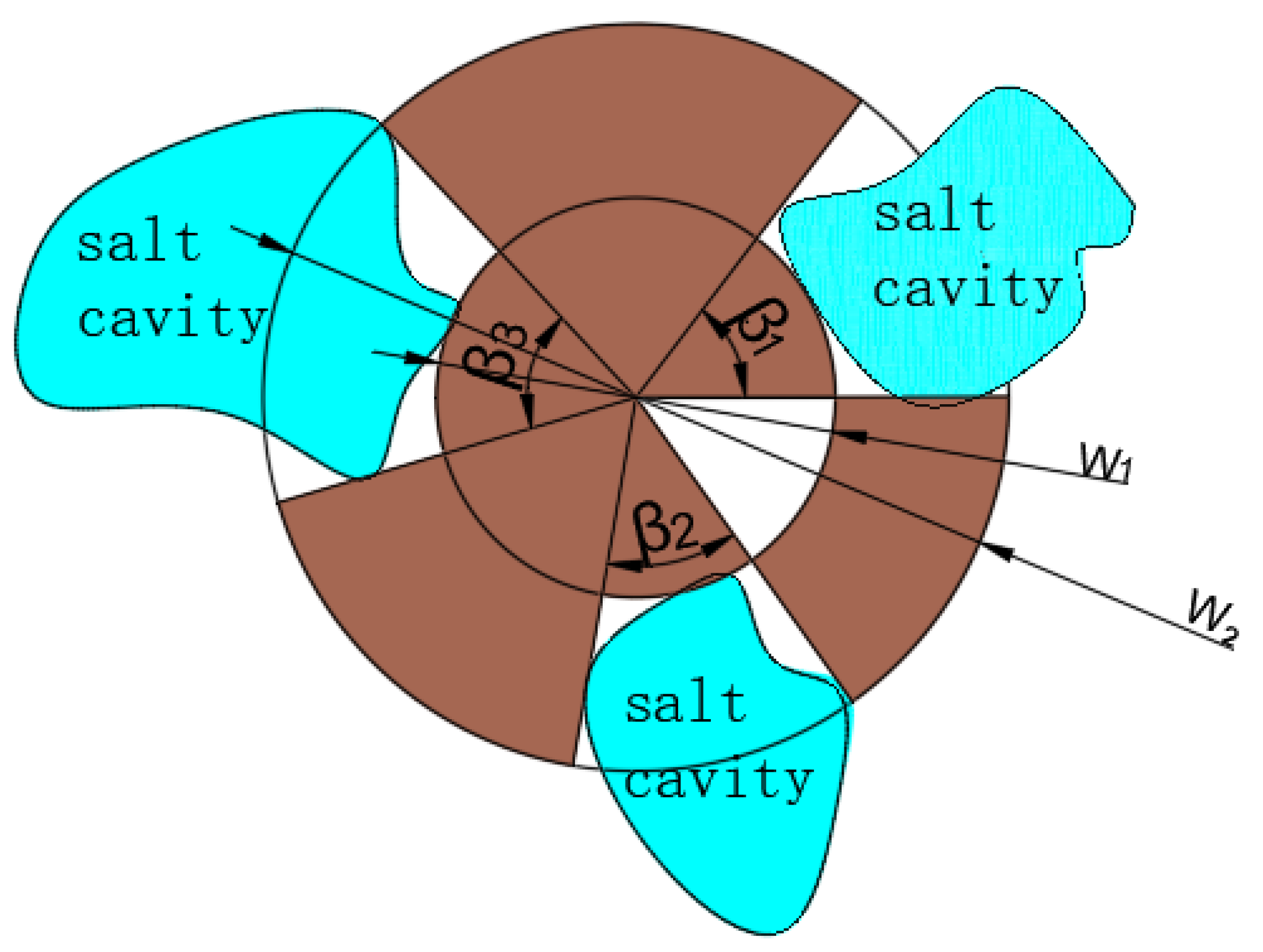
The group cavern model evolved from the double-cavern model, it is usually used to analyze the stability of the pillars of three or more salt caverns, as shown in Figure 7. The group cavern model is a three-dimensional pillar calculation method formed based on a plane problem. As shown in Figure 7, the multiple-cavern pillars were transformed into an axisymmetric problem. Through a calculation method such as the dual-cavern model, the stress in polar coordinates can be solved.
In polar coordinates, the radial horizontal stress is influenced by two stresses (e.g., ground stress, and the pressure in the cavern). The tangential stress is affected by the aspect ratio of the pillar. Additionally, the following group’s equation was adopted [25].
σ ¯ v = ( σ o P γ ( 1 ( W / W 0 ) 2 ) ) / ( 1 γ ( 1 ( W / W 0 ) 2 ) ) σ ¯ r = γ [ P + 0.1 σ ¯ v ( W / H ) ] + ( 1 γ ) σ 0 σ ¯ θ = 0.1 σ ¯ v ( W / H )
where the P represents the pressure of the cavern; H represents the height of the pillar; W represents the inner circle diameter; W 0 represents the outsider circle diameter; γ = β / 360 ; represents initial ground stress; σ ¯ v represents average vertical stress of the pillar; σ ¯ r represents average radial stress of the pillar; and σ ¯ θ represents average tangential stress of pillar. The group cavern model is a common way to calculate the stability of the pillars. Its safety coefficient is smaller than the double-cavern model. However, the actual storage group construction process is mostly a group cavern salt cave model; this also illustrates the importance of the group cavern.

The Cusp Displacement Catastrophe Model

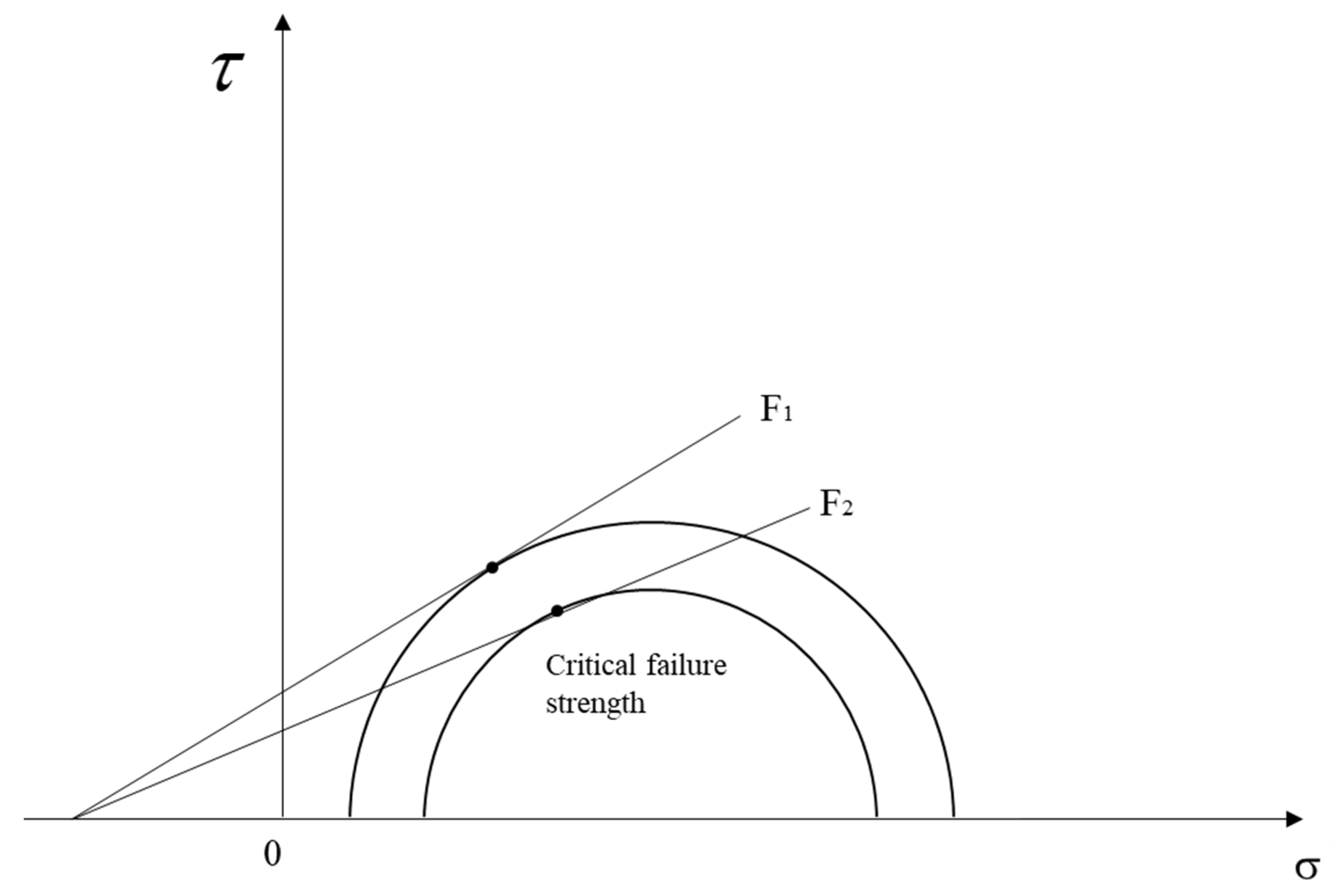
The cusp displacement catastrophe model is precise, in contrast to the above model. For the numerical simulations in the geotechnical world, the finite element strength reduction method is always used. This method uses a strength reduction formula to increase the reduction coefficient, which reduces the material’s failure strength continuously. Additionally, this reduced failure strength is substituted in the model, as shown in Figure 8. When the pillar reaches a failure state, the corresponding reduction factor is the safety factor of the pillar.
G = C / F Φ = arctan ( tan ϕ / F )
where the C represents cohesion; ϕ represents internal friction angle; G represents reduced cohesion; Φ represents the reduced friction angle; and F represents reduction factor. When using the effective strength reduction model to evaluate the stability of the pillar, the irregularity of the pillar may lead to errors. To eliminate it, Wang [20] proposed to establish a cusp displacement catastrophe model based on catastrophe theory and nonlinear dynamics theory.
Through the above model, the law of jump changes in the state of the structural system and corresponding critical conditions for sudden changes was obtained. Constructing the discriminant equation of pillar stability through this property:
f ( u , v ) = 4 u 3 + 27 v 3
where f ( u , v ) are the control variables, and the specific criteria are:
  • IF f ( u , v ) > 0, the pillar is stable;
  • IF f ( u , v ) = 0, the pillar is prone to instability;
  • IF f ( u , v ) < 0, the pillar is unstable.
This method is more suitable for evaluating the stability of a salt pillar of a storage facility and has been applied in practical engineering. The specific implementation process of the cusp displacement catastrophe model in evaluating the pillar design stability is shown in Figure 9.
This model can be accurately quantified in the process of determining the stability of the pillar. Through this model to analyze the pillar stability factors, the safety factor will decrease with the accumulation of buried depth and time, internal pressure, and pillar width.
In summary, numerical simulation is a fantastic way to test the stability of the pillar, and it is a useful tool for studying the stress changes in the pillar after the excavation. However, obtaining accurate pillar parameters is a difficult job, especially the layer mechanical parameters. Furthermore, some parameters must be measured on-site. Additionally, the time effect of numerical simulation may be different in contrast to practical engineering. Therefore, the numerical simulation should adopt to the actual site.
We compared the similarities and differences between the formula method and the numerical simulation method in the theory of salt pillar design, as shown in Table 4.

4. The Factors That Influence the Salt Pillar Design

4.1. The Width of the Salt Pillar

From the perspective of engineering analysis, the main function of the salt pillar in storage stability is the change in its bearing capacity. In addition, the width determines the bearing capacity of the pillar. Zhang put forward the conclusion that the pillar width should be greater than 1.5 times the maximum diameter of the salt cavern by constructing a similar model of a layered salt rock underground storage cavern [10]. The width of the pillar can also be smaller than the diameter of a single cavern [16].
The width of the pillar is an important indicator that affects the safety of the storage. In the empirical formula, the relationship between the width of the pillar and the gas storage can be shown as:
L D 2
The variable L represents the maximum distance of the salt cavern; D represents the maximum diameter of the salt cavern. This empirical formula analyzes the pressure difference between the two caverns at different intervals, and the expansion area between the caverns. When the distance between the caverns is twice the cavern diameter, the influence of the pressure difference is relatively small. Therefore, it is usually used as the width of the engineering safety pillar. The width of the pillar has an important significance in engineering applications. It directly determines the resource utilization rate of the salt rock and the stability of the cavern.
The optimal pillar width has always been a topic discussed by scholars. The determination of pillar widths mostly depends on empirical formulas, lacking certain theoretical analysis and verification. Wu et al. [19] proposed that the intermediate stress of the salt pillars between the caverns should be less than the long-term strength of the salt rock. The width of the salt pillars should be greater than a specified value, and the width B can be determined by the following formula:
B = K D
where represents safety factors that range from 1.5 to 3.0. Different variables have a major influence on salt pillar design, e.g., The width of the pillar should not be too large, otherwise, it will cause waste of salt rock resources, and it should not be too small. Too small a width will cause instability and damage, resulting in a large area of roof pressure, and may even cause the entire gas storage group to fail. Therefore, it is vital to determine a reasonable pillar width according to the specific environment.
Numerical simulation can analyze the influence of pillar width on the stability of caverns. Wu et al. simulated the change in the vertical stress under the internal cavern stress of 7 MPa and different pillar widths [21]. With the decrease in W (the width of the pillar), the vertical stress in the pillar at the symmetry axis continues to increase, and the pillar may be destructed. Xue simulated the maximum and minimum reasonable pillar widths based on the double-cavern model and obtained the safe pillar widths range of 1.5~2.5 D [39]. This range has been verified in the test of the Jiangsu Jintan Salt Cavern Gas Storage project.
In addition, there actually exists a convergence limit situation for the value of the pillar width, and the current design of the pillar width aims to improve safety as the main purpose; in different regions, there exist differences in the nature of the salt rock pillar width; in the same region, the salt rock pillar width under different ground stress still varies. However, in the actual production process, considering various factors such as safety, the actual limit of the salt pillar width during engineering will be much larger than design width. There is also a limit to the design of the dissolution cavern of the salt pillar. For the gas storage groups, the shrinkage standard of the cavern is 30% shrinkage for 30 years, where 30 years is determined by the service life of the pipeline, while the limit of 30% shrinkage of the cavern is an engineering prediction, and its convergence is also related to parameters such as the amount of subsidence of the surface building where the cavern is located.
Additionally, halogenation can have an effect on the width of the pillar. If the pillar itself is under net water pressure, the stability of the pillar will be affected by the erosion of the brine through the fractures when its three-way stress breaks down. In addition, if the net water pressure of the salt rock pillar itself is not broken, then the pillar itself is still in a dense state, under such conditions, the erosion of brine can only start from the surface of the salt rock pillar and gradually erode from the edge to the inside, and the halogenation at this time has little effect on the pillar.
In the design of the pillar at the salt cavern of Huangchang in the Jianghan Basin, the pillar width was a key parameter. The salt caverns had a depth of about 2000 m, a temperature of 83°, and a formation pressure of 46 MPa [26]. Because of this, the construction of these salt caverns must consider the impact of high ground stress and temperature, otherwise, the salt cavern may leak, converge, and be penetrated.
The maximum safe distance between two caverns is consists of the maximum diameter of the cavern, the maximum deviation distance of the borehole, and the minimum safety pillar. Through the static analysis and rheological analysis of the cavern, we can ensure the optimum pillar width. We finally obtained that the width of the safe pillar is about two times that of the cavern diameter.
During the design of the Jintan salt caverns, Yang et al. [31] proposed a dense design scheme for underground storage. To fully use the salt rock, they set four caverns into one group and set multiple groups in this way. The pillar width of the four salt caverns in a group is 0.7 D (D is the maximum diameter of the salt cavern), and the different group’s pillar width is 1.5 D. The underground salt rock space can be utilized to the maximum when we reduce the width of the pillar in the traditional design.

4.2. The Salt Pillar Injection–Withdrawal Process

The injection–withdrawal of the gas storage is a periodical loading and unloading process [40], and the change in the load will have an impact on the stability of the pillar. After building the cavern for gas storage, gas injection, and brine discharge, periodic performing of injection and withdrawal are carried out. During the gas injection and brine removal stage, Zhao [40] found that before removing the brine, the creep of the salt rock caused the minimum principal stress to increase, and the maximum displacement after the brine removal was slightly larger than that before the brine removal. During the brine removal, the pressure in the cavern remains almost unchanged. Therefore, the gas injection and brine removal stage have less interference with the pillar stability.
In the cyclical injection and withdrawal, the largest impact on the stability of the pillar is the synchronized gas injection and gas withdrawal. Additionally, the salt cavern gas storage operations can be divided into four stages: maintaining low pressure, gas injection that increases pressure, maintaining high-pressure storage, and gas withdrawal that again reduces pressure.
During this cyclic loading and unloading of the pressure in the cavern, the elastic modulus, the formation pressure, and the cyclic load constantly change, and the salt rock produces corresponding elastic deformation, plastic deformation, and creep deformation. Finally, the stability of the salt pillar may be destroyed.
To study whether the injection and production of the two salt caverns are synchronized, the creep displacement of the pillar under different injection and mining conditions through FLAC3D are simulated. Finally, as the ratio of the pillar width to the salt cavern decreases, the vertical stress distribution across the pillar changes. It becomes a single peak, the plastic zone appears to connect, and the stability of the pillar is destroyed. Therefore, the simultaneous gas injection has less impact on the pillars, which is conducive to the stability of the gas storage [18].
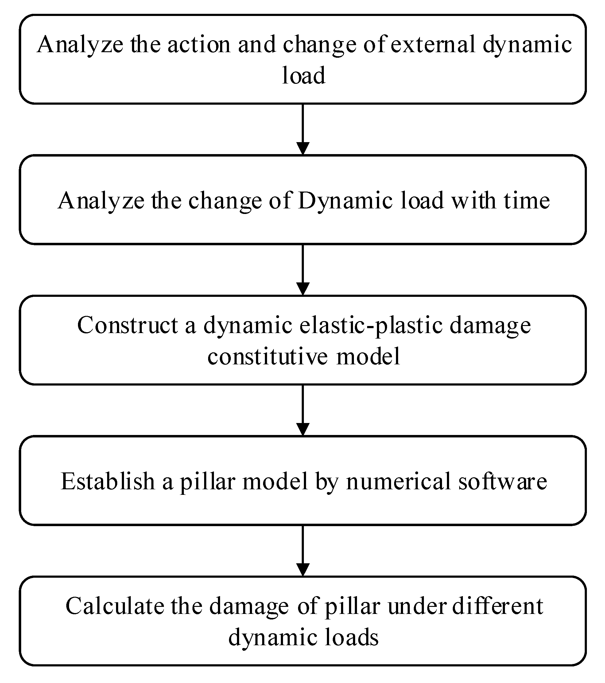
In the process of salt cavern injection and extraction, the gas inside the salt cavern will be filled and evacuated, and at the same time, the seismic waves will also carry out certain disturbances and perturbations. In this process, the salt pillar inside the salt cavern will also undergo certain dynamic loads. In order to analyze this dynamic response, a new dynamic damage intrinsic model needs to be established, and then numerical simulation software is used to simulate this dynamic response. The steps for the analysis of the dynamic response of the salt pillar are shown in Figure 10.

5. Characteristics and Development Trends of Existing Theories

Comprehensively analyzing the three development stages of salt pillars, viz., mechanical experiments, numerical simulations to calculations, and large-scale experiments have been discussed.
However, the three stability design theories have some problems in quantitatively judging the stability of the pillar. The reliability theory starts from the limit state function and achieves the quantitative analysis through random variables and the Monte Carlo method, and it determines parameter N by ANSYS. However, the stability criterion of the N is difficult to obtain.
The strain energy theory of the time-varying effect combines the strength criterion of the pillar with the strain–time curve of the pillar. It regards the time-varying stress of the salt pillar as a key factor for judging whether the pillar shrinks or not, but it ignores the shape and the pillar end effect. The catastrophe theory based on the beam structure is an effective way to explain the instability energy of the pillar.
The catastrophe theory based on beam roof structure explains the instability of the pillar from the energetic point of view, but the model has a relatively high degree of simplification. So, it is difficult to apply in general geological conditions.
Based on this theory, two methods to design optimum salt pillar, i.e., the formula method and numerical simulation method, are considered.
The formula method is mainly using closure and stability to analyze the pillars. In actual engineering, we should distinguish the importance of two indicators according to the specific working conditions. However, the determination of this specific judgment index is not established yet. Because of the complexity of the salt rock storage conditions and the different mechanical properties of the salt rock in different regions, a specific standard system for controlling the storage spacing still needs to be improved.
Establishing different models to analyze the salt pillar by numerical simulation is essential, but a potential shortcoming is the accuracy of parameter selection and the hypothesis of experimental simulation. There is a lack of specialized mine pillar design software. In the simulation process, the parameters are usually obtained by on-site sampling, laboratory testing, or empirical formulas. The inaccuracy of the parameters will have a major influence on the design and stability analysis of the pillar. Therefore, it is necessary to establish an in situ experimental parameter collection and processing system.
In terms of pillar instability, the orthogonal experiment is still an important method and means to determine the stability of the pillar. Orthogonal experiments can determine the major factors that affect the stability of the pillar. Reasonable pillar width has always been the focus of research. Empirical formulas and numerical simulations verify are common ways to design pillar width. A width 1.5 to 2 times that of the diameter is commonly used as the pillar width.
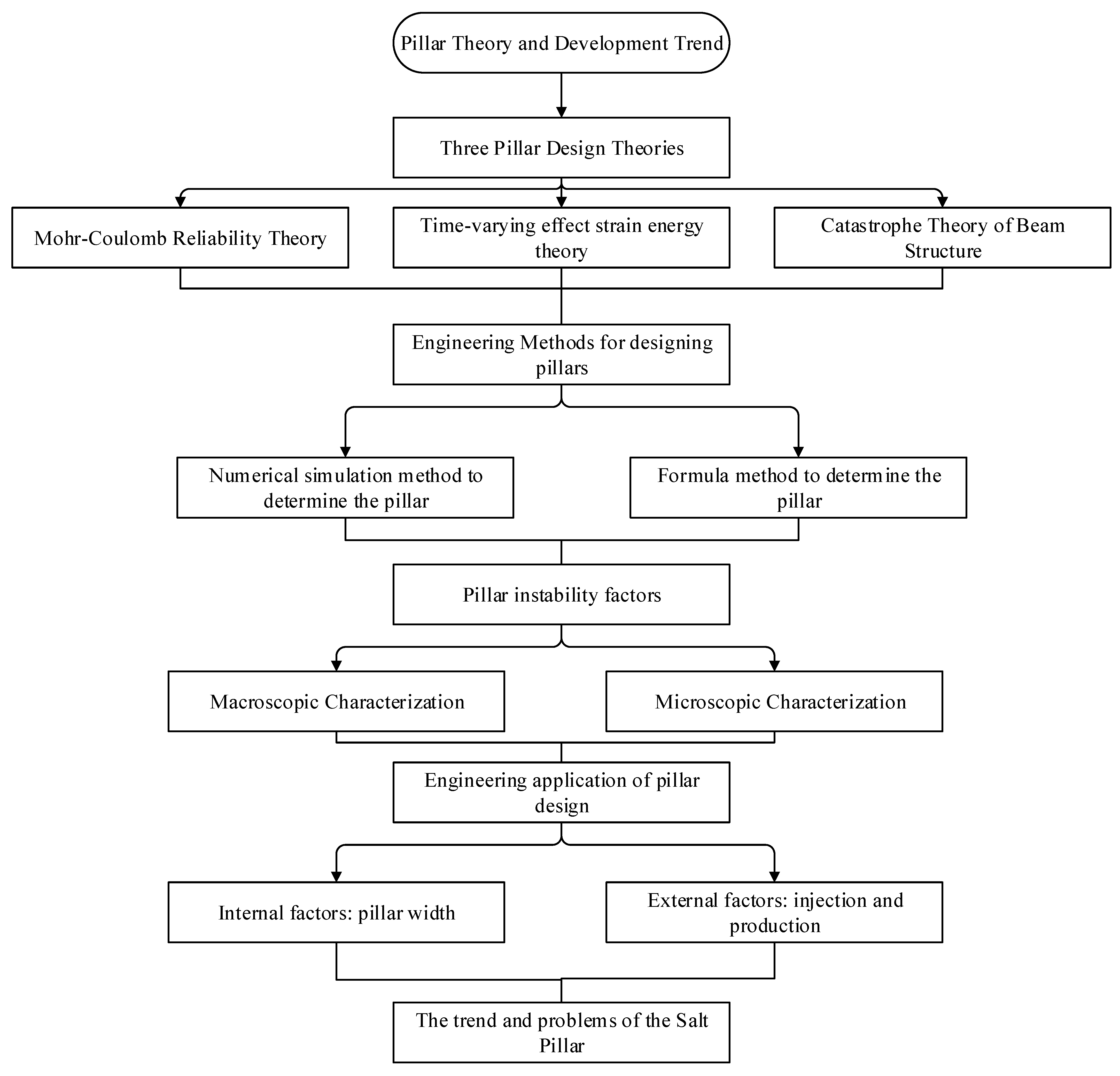
In conclusion, the specific theoretical development relationships for pillar stability analysis are shown in Figure 11.

6. Conclusions

This essay analyzes the pillar stability design theory and research methods, focusing on the safety of pillars problem of salt cavern gas storage. Although scholars have conducted a lot of experiments and simulation studies on salt pillars, and continuously optimized the calculation methods of pillar design, there are still some controversies about the method of pillar maintenance and the prediction of salt cavern stability. It is urgent to solve the systematic theory of pillar stability. With the large-scale development of salt caverns in China, rational design of mine pillars and full use of salt rock formations are important to China’s energy stability and economic development. Therefore, we concluded the design and stability of safe salt pillars:
  • The salt pillar stability should consider the mechanical properties of salt rock in different areas. Safe pillars are an important design factor for the safe and stable operation of gas storages. Therefore, it is necessary to constantly explore the current state of China’s salt rock and field conditions in the design of safe pillars. Establishing a database of mechanical properties of salt rock in different regions of China and realizing an engineering classification of salt rock is urgent. Conducting targeted research on salt pillars according to the salt rock conditions in the area is necessary.
  • From a comprehensive analysis point of view, many theories need to be improved in the field of gas storage pillar research. The research methods of coal pillar theory can contribute to the salt pillar development. It is necessary to continuously increase the intensity of basic research on salt pillars, to make breakthroughs in the mechanism and retention of pillars.
  • In the actual engineering application of safe pillars, a pillar maintenance method must be compatible with the actual engineering case. Firstly, a comprehensive evaluation model and pillar design systematic methods is established, and the main factors according to specific geological conditions are chosen. Next, related experiments should be carried out according to the precise factors. During the experimental period, the difference in the mechanical properties of the salt rock should be considered. Finally, a suitable salt pillar design scheme should be chosen according to experimental results.
  • The salt pillars numerical simulation should be systematic, large-scale, and integrated. Additionally, a comprehensive integrated system of salt cavern gas storage and safe pillars determination also needs to be developed. New experimental instruments and equipment, which can be verified automatically, to evaluate pillars need to be explored.

Author Contributions

H.M.: investigation, writing—review and editing. X.W.: formal analysis, writing—original draft, writing—review and editing. X.S.: writing—review and editing. X.L.: validation. W.B.: investigation. L.G.: investigation. All authors have read and agreed to the published version of the manuscript.

Funding

This work was financially supported by The General Program of National Natural Science Foundation of China, No. 51874274; Science Foundation for The Excellent Youth Scholars of National Natural Science Foundation of China, No. 52122403; Youth Innovation Promotion Association of Chinese Academy of Sciences (2019324); Major Research Development Program of Hebei province (Grant No. 21374101D).

Institutional Review Board Statement

Not applicable.

Informed Consent Statement

Not applicable.

Data Availability Statement

Not applicable.

Acknowledgments

The authors are sincerely grateful to J.J.K. Daemen (Mackay School of Earth Sciences and Engineering, University of Nevada, USA) for his linguistic assistance during the preparation of this manuscript.

Conflicts of Interest

The authors declare no conflict of interest.

References

  1. Ran, L.N. Development status and trends of underground gas storage in the world. In Proceedings of the 2016 National Natural Gas Academic Annual Conference, Yinchuan, China, 28 September 2016. [Google Scholar]
  2. Ding, G.S.; Xie, P. Current status and development prospects of underground gas storage in China. Nat. Gas Ind. 2006, 6, 111–113+70. [Google Scholar]
  3. Zhang, N.; Liu, W.; Zhang, Y. Microscopic Pore Structure of Surrounding Rock for Underground Strategic Petroleum Reserve (SPR) Caverns in Bedded Rock Salt. Energies 2020, 13, 1565. [Google Scholar] [CrossRef] [Green Version]
  4. Jing, W.J.; Yang, C.H.; Chen, F. Risk assessment of underground salt rock oil/gas storage based on accident statistical analysis. Rock Soil Mech. 2011, 32, 1787–1793. [Google Scholar]
  5. Yang, Q.; Pan, Y.W.; Deng, J.Q. Critical spacing and damage analysis of underground salt rock storage group. Chin. J. Rock Mech. Eng. 2012, 31, 1729–1736. [Google Scholar]
  6. Yang, C.H. Research on key mechanical problems in deep petroleum storage in layered salt rock mass. In Proceedings of the Academic Conference of the Chinese Society of Mechanics’2005, Beijing, China, 26 August 2005. [Google Scholar]
  7. Junthong, P.; Khamrat, S.; Sartkaew, S.; Fuenkajorn, K. Determination of time-dependent strengths of salt pillars based on strain energy principle. Int. J. Min. Sci. Technol. 2019, 29, 273–279. [Google Scholar] [CrossRef]
  8. Devries, K.L. Laboratory Testing in Support of a Bedded Salt Failure Criterion. In Proceedings of the Solution Mining Research Institute Fall Meeting 2003, Washington, DC, USA, 11–12 December 2012. [Google Scholar]
  9. Ren, S.; Jiang, D.Y.; Liu, X.R. Catastrophe theory analysis of pillar stability between rock salt cavern well groups. China Min. 2004, 1, 71–73. [Google Scholar]
  10. Zhang, Q.Y.; Duan, K.; Xiang, W. Three-dimensional rheological model test study on operation stability of deeply layered salt rock underground gas storage group affected by extreme risk factors. Chin. J. Rock Mech. Eng. 2012, 31, 1766–1775. [Google Scholar]
  11. Zhang, Q.Y.; Duan, K.; Jiao, Y. Physical model test and numerical simulation for the stability analysis of deep gas storage cavern group located in bedded rock salt formation. Int. J. Rock Mech. Min. Sci. 2017, 94, 43–54. [Google Scholar] [CrossRef]
  12. Wang, H.; Cao, H.; Yu, S.B.; Qin, X.S.; Yuan, Y. Limit equilibrium method for the design of underground mining pillars in salt mines. China Min. Ind. 2016, 25, 267–269. [Google Scholar]
  13. Liu, M.Y.; Chi, X.W.; Zhang, Y.L. Reliability design of pillar structure. J. Wuhan Univ. Technol. 1998, 1, 54–56. [Google Scholar]
  14. Liu, M.Y.; Xu, C.Y. Stability analysis of pillars in underground goaf. Min. Metall. Eng. 2000, 1, 19–22. [Google Scholar]
  15. Beckenham, R.F.; Urai, J.L. Pillar deformation-induced surface subsidence in the Hengelo brine field. In The Mechanical Behavior of Salt–Understanding of THMC Processes in Salt; CRC Press: Leiden, The Netherlands, 2007. [Google Scholar]
  16. Mo, J.; Liang, W.G.; Zhao, Y.S.; Yang, H.J.; Qu, D.A. Study on the influence of pillar width on the operation stability of gas storage. J. Taiyuan Univ. Technol. 2009, 40, 279–282. [Google Scholar]
  17. Liu, J.; Song, J.; Zhang, Q.Y.; Zhang, W.Q.; Jia, C.; Li, S.C.; Yang, C.H. Numerical calculation and analysis of the interval between salt rock underground gas storage groups. Chin. J. Rock Mech. Eng. 2011, 30, 3413–3420. [Google Scholar]
  18. Wang, T.T.; Yan, X.Z.; Yang, H.L.; Yang, X.J. Research on pillar stability between multi-layered salt cavern gas storage groups. Acta China Coal Soc. 2011, 36, 790–795. [Google Scholar]
  19. Wu, W.; Hou, Z.M.; Yang, C.H. Research on the Stability Evaluation Criteria of Underground Energy (Oil and Natural Gas) Storage in Salt Rock. Chin. J. Rock Mech. Eng. 2005, 14, 2497–2505. [Google Scholar]
  20. Wang, T.T. Stability analysis of the pillars between bedded salt cavern gas storages by cusp catastrophe model. Sci. China Technol. Sci. 2011, 54, 1615–1623. [Google Scholar] [CrossRef]
  21. Wu, Z.D.; Wang, Y.; Zhang, M.; Li, Z.J. Research on pillar design and safety of salt cavern gas storage. In Proceedings of the 2018 National Natural Gas Conference, Fuzhou, China, 14 November 2018. [Google Scholar]
  22. Wang, T.; Yang, C.; Yan, X.; Li, Y.; Liu, W.; Liang, C.; Li, J. Dynamic response of underground gas storage salt cavern under seismic loads. Tunn. Undergr. Space Technol. 2014, 43, 241–252. [Google Scholar] [CrossRef]
  23. Zhao, S.; Fang, X.L.; Liu, W.; Yan, X.Z.; Han, L.L. Pillar stability of underground salt cavern gas storage based on reliability theory. Oil Gas Storage Transp. 2014, 33, 839–843. [Google Scholar]
  24. Uri, L.; Ňup Rek, R. Numerical Analysis of the Stability of Lignite Pillars. Procedia Eng. 2017, 191, 310–316. [Google Scholar]
  25. Li, Z.J. Analysis and Application of Pillar Stability of Deep Salt Rock Gas Storage; Shandong University: Shandong, China, 2018. [Google Scholar]
  26. Fu, X.F. Stability analysis of Huangchang salt cavern underground gas storage in Jianghan Basin. J. Shanxi Datong Univ. (Nat. Sci. Ed.) 2020, 36, 73–75. [Google Scholar]
  27. Song, W.D.; Cao, S.; Fu, J.X.; Jiang, G.J.; Wu, F. Sensitivity analysis, and application study of factors affecting pillar stability. Rock Soil Mech. 2014, 35, 271–277. [Google Scholar]
  28. Zhang, N.; Shi, X.; Zhang, Y.; Shan, P. Tightness Analysis of Underground Natural Gas and Oil Storage Caverns with Limit Pillar Widths in Bedded Rock Salt. IEEE Access 2020, 8, 12130–12145. [Google Scholar] [CrossRef]
  29. Baryakh, A.A.; Asanov, V.A.; Toksarov, V.N.; Gilev, M.V. Evaluating the residual life of salt pillars. J. Min. Sci. 1998, 34, 14–20. [Google Scholar] [CrossRef]
  30. Van Sambeek, L.L. Salt Pillar Design Equation; Series on rock and soil mechanics; Trans Tech Publications: Clausthal-Zellerfeld, Germany, 1998; pp. 495–508. [Google Scholar]
  31. Yang, C.; Wang, T.; Li, J.; Ma, H.; Shi, X.; Daemen, J.J.K. Feasibility analysis of using closely spaced caverns in bedded rock salt for underground gas storage: A case study. Environ. Earth Sci. 2016, 75, 1138. [Google Scholar] [CrossRef]
  32. Staudtmeister, K.; Rokahr, R.B. Rock mechanical design of storage caverns for natural gas in rock salt mass. Int. J. Rock Mech. Min. Sci. 1997, 34, 300. [Google Scholar] [CrossRef]
  33. Yin, S.H.; Wu, A.X.; Li, X.W. Orthogonal range analysis of sensitivity to factors affecting pillar stability. J. China Coal Soc. 2012, 37, 48–52. [Google Scholar]
  34. Zhurkov, S.N. Kinetic concept of the strength of solids. Int. J. Fract. 1984, 26, 295–307. [Google Scholar] [CrossRef]
  35. Guo, K.Y. Study on the Creep Characteristics of Salt Rock; Chongqing University: Chongqing, China, 2004. [Google Scholar]
  36. Zhang, S.Z. Analysis of the Roof-Pillar Stability of the 1# Copper Mine with the Room-Pillar Method in the Dahongshan Iron Mine; Kunming University of Science and Technology: Kunming, China, 2014. [Google Scholar]
  37. Wang, X.S. Study on Stability of Salt Rock Gas Storage during Operation Period; Chongqing University: Chongqing, China, 2009. [Google Scholar]
  38. Gong, J.W.; Cui, J.J.; Xi, X.W.; Lin, K. FLAC numerical simulation software and its application in geology. Tecton. Metallog. 2002, 3, 321–325. [Google Scholar]
  39. Xue, H.; Han, C.Y.; Xiao, B.Y.; Yan, A.H.; Li, X.M. Stability analysis of salt cavern double reservoir cavern with reasonable pillar width. Oil Gas Storage Transp. 2021, 40, 753–760. [Google Scholar]
  40. Zhao, K.L. Study on the Availability of Underground Salt Rock Gas Storage in the Process of Gas Injection and Production; Graduate University of Chinese Academy of Sciences (Wuhan Institute of Rock and Soil Mechanics): Wuhan, China, 2009; p. 672. [Google Scholar]
Figure 1. Two salt pillars between salt caverns.
Energies 15 07570 g001
Figure 2. The current development of salt pillar design research.
Energies 15 07570 g002
Figure 3. Salt pillar destruction form. (a) Tension Failure; (b) Shear Failure; (c) Swelling Failure; (d) Slip Failure; (e) Collapse Failure.
Energies 15 07570 g003
Figure 4. Destruction form of the instability salt pillar.
Energies 15 07570 g004
Figure 5. Pillar stability analysis based on reliability theory.
Energies 15 07570 g005
Figure 6. Schematic diagram of the double-cavern model.
Energies 15 07570 g006
Figure 7. The three-dimensional pillar stress model.
Energies 15 07570 g007
Figure 8. The change in strength reduction failure graph.
Energies 15 07570 g008
Figure 9. The realization process of cusp displacement catastrophe model in the judgment of pillar stability.
Energies 15 07570 g009
Figure 10. Salt pillar under the dynamics load.
Energies 15 07570 g010
Figure 11. The development diagram of pillar theory.
Energies 15 07570 g011
Table 1. Basic theory of salt pillar design.
WriterTheoryResearch Point
Prapasiri [7]the principle of strain energythe strength of the salt pillar
Kerry L. De [8]a damage expansion criterionthe strength of the salt pillar
Ren [9]a catastrophic theoretical modelthe pillar instability
Zhang [11]a three-dimensional rheological modelthe deformation characteristics of salt pillar
Wang [12]limit balance methodlimit width of the pillar
Liu [13,14]the mass mechanical parameters and external loadsthe stability of the salt pillar
Bekendam [15]the subsidence rate mapthe impact of the salt pillar
Table 2. Comparison of different mine pillar design theories.
Theory NameAdvantagesDisadvantagesPractical Application Conditions
The Mohr–Coulomb criterionImplemented quantitative analysis of salt pillar design and probabilistic-based algorithmsThe size of the random variables used lacks corresponding definition criteriaThis method is advantageous when the design of the pillar where it is located has a large number of variables, and the data has a large randomness.
The strain energy theoryThis theory, based on the time-varying effect of salt rock design, has more applicability than the traditional strength criterionThe shape effect and end effect of the salt pillar are ignored and need to be experimentally determinedThis method is used when the creep deformation of the designed salt pillar is large, and sufficient experimental time is available to conduct it.
The catastrophe theorySimple model, easy force analysis, and salt pillar design depends on internal energyComplex geological conditions of the salt pillar does not meet this requirementThis method is applicable if the geological conditions are simple and the strength of the pillar and roof is known
Table 3. Numerical simulation on FLAC3D.
WriterResearch PointSoftware
Mo [16]the influence of pillar widthFLAC3D
Wang [18]the influence of pillar width, internal pressure, buried depthFLAC3D
Wu [19]the stability rating standardFLAC3D
Wang [22]a dynamic elastoplastic modelFLAC3D
Zhao [23]the stable failure functionFLAC3D
Lukas [24]the influence of bolt supportFLAC3D
Table 4. Comparison of different mine pillar design methods.
Theory NameSpecific MethodMethod DescriptionAdvantagesDisadvantagesInstructions
Equation method(1) Mohr–Coulomb criterionThe gas caverns spacing must be such that the stress in the middle part of the pillar is less than the strength of the salt rock during operationIt is simple to use the pillar safety factor as an indicator of pillar design by specifying only the compressive strength and positive stress to which the pillar is subjectedThe method differs to a certain extent from the specific actual project, and the salt pillar design is too large, wasting salt rock resourcesThis design method is used as the most traditional way of designing mineral pillars, analyzing the minimum width of the salt pillar design process from a mechanical point of view and formula.
(2) Point safety factor methodRatio of the value of the ultimate damage state that may be reached at a point of the column to the actual value of the stress state at that pointEstablishing a design method for salt pillars based on the stress action point of pillar damageThere may be some gaps in the actual situationThis method is an innovation of the traditional Mohr–Coulomb criterion, which considers the strength of the action at a point of salt pillar rupture.
(3) Damage expansion criterionFormulation based on the second invariant of the plastic mechanics partial stress tensorA theory based on the occurrence of plastic expansion of rocks, which is consistent with the properties of rocksThe criteria for damage expansion of the salt pillar need to be obtained experimentally, etc.Expansion of the criteria for the design of salt pillars based on the plasticity theory formula method
Numerical simulation(1) Double-cavern modelSalt pillar design method based on the establishment of two cavernsSimulation of the plastic zone and displacement variation of the salt pillar at different widthsMay be different from the actual situation force, influenced by the mesh divisionStability analysis of salt pillar design based on finite difference method
(2) The group modelSalt pillar design method based on the establishment of three cavernsSimulation of the plastic zone and displacement variation of the salt pillar at different widthsInfluenced by the mesh divisionStability analysis of salt pillar design based on finite difference method
(3) The cusp displacement catastrophe modelAnalysis by finite unit strength reduction methodSalt pillar design by discount factor is simpler and meets safety pillar criteriaThere may be discrepancies with the actual projectThe idea based on the discount-subtraction method can simplify the complexity of the numerical simulation process
Publisher’s Note: MDPI stays neutral with regard to jurisdictional claims in published maps and institutional affiliations.