
Alternative Fuel Generation from Dangerous Solid Waste in a Protected Environmental Area


Abstract
:1. Introduction
2. Materials and Methods
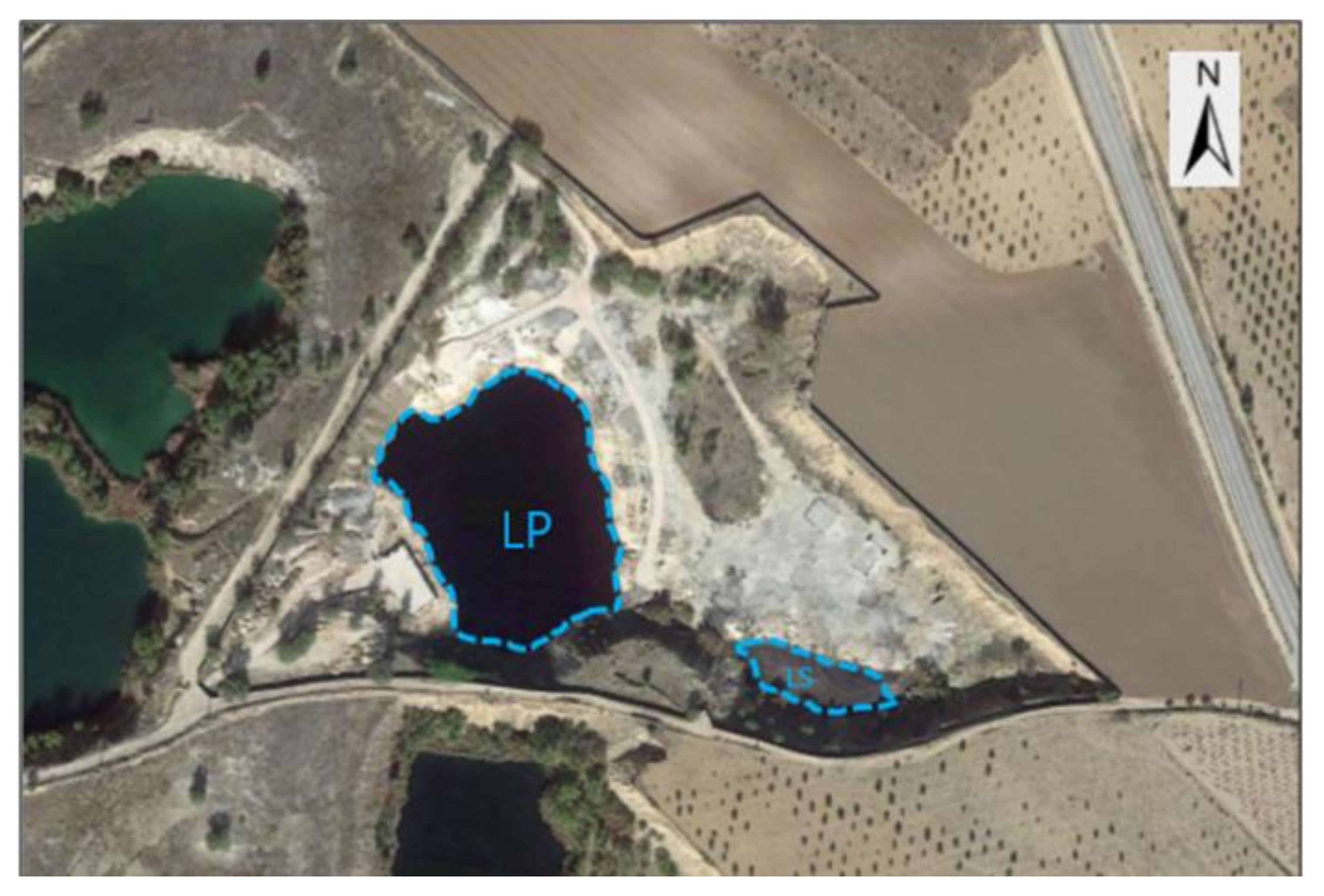
2.1. Settling Ponds Description
2.2. Characterization of the Waste
- It is a material with an absence of stratification and without differences, but it does have punctual intercalations of calcareous filler of 20 to 50 cm in strength.
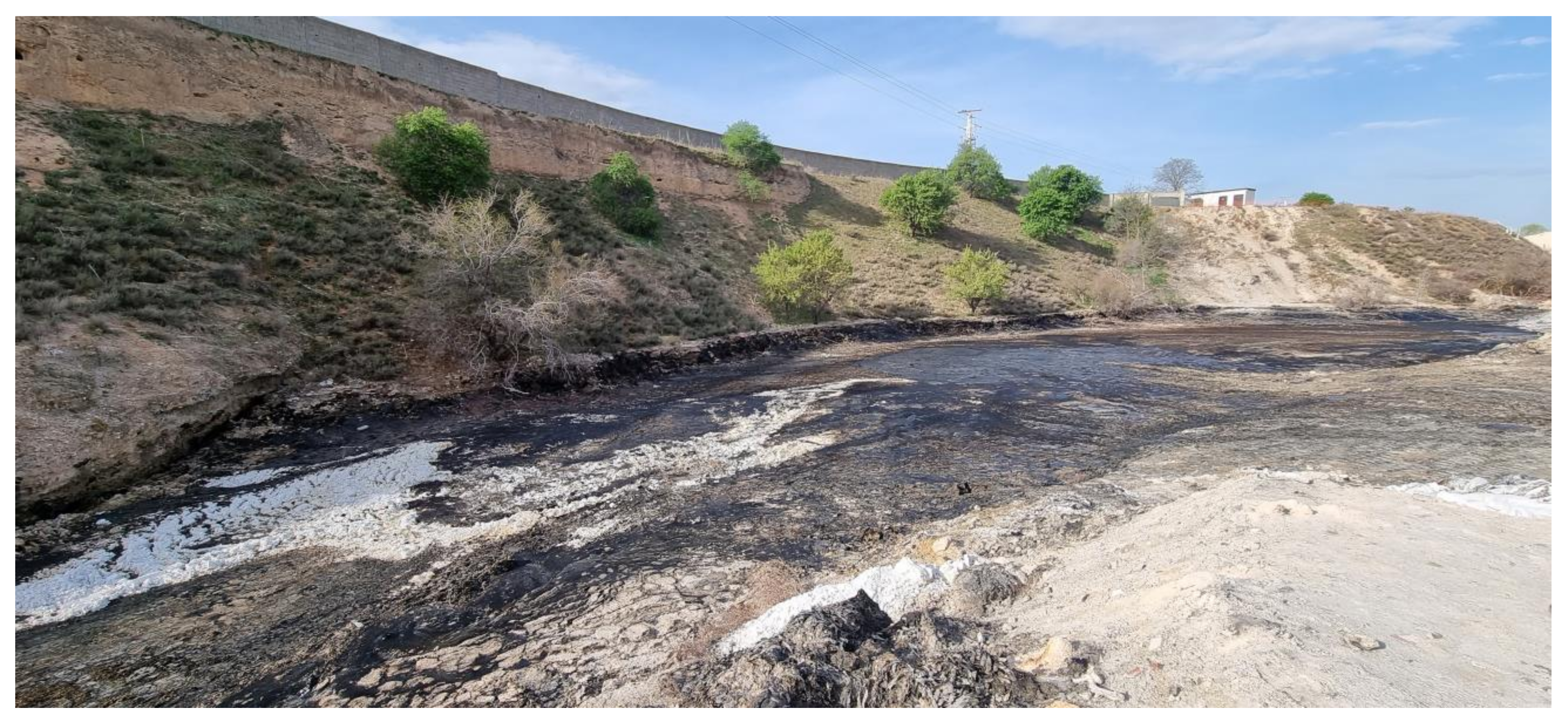
- The contaminant material is black and solid, and it occasionally looks like plastic. Additionally, when in repose, its state is semisolid.
- In 8 out of the 15 trial pits made, it was possible to reach the base of the settling pond, obtaining irregular depth and impermeable materials, such as gravel and sand, from those trial pits.
- Layer C: this layer has the highest volume of the Laguna Principal, mainly formed by oily petroleum sulphonates, highly viscous and black. Its thickness varies depending on the topography of the settling pond, so it is not constant, reaching a depth of 6 m. Its density, fluidity and viscosity vary depending on the depth: the deeper it is, the more viscous the material becomes.
- Layer D: this layer is denser and deeper than Layer C. It is black and is formed by heavy hydrocarbon that makes it possible to carry out extraction pumping at ambient temperature. It is highly viscous, even though it is also slightly fluid. The density varies, with an average density of 0.5 m. The origin of the material is the thermal de-asphalting carried out to recover oils.
- Silt Layer: This is a deeper layer that occupies the bottom and part of the talus. It is formed by silt and sandy silts that make the layer impermeable and act as a containment for heavy hydrocarbons, PAHs and metals, followed by sands and gravels.
2.3. Alternative for the Use of Waste
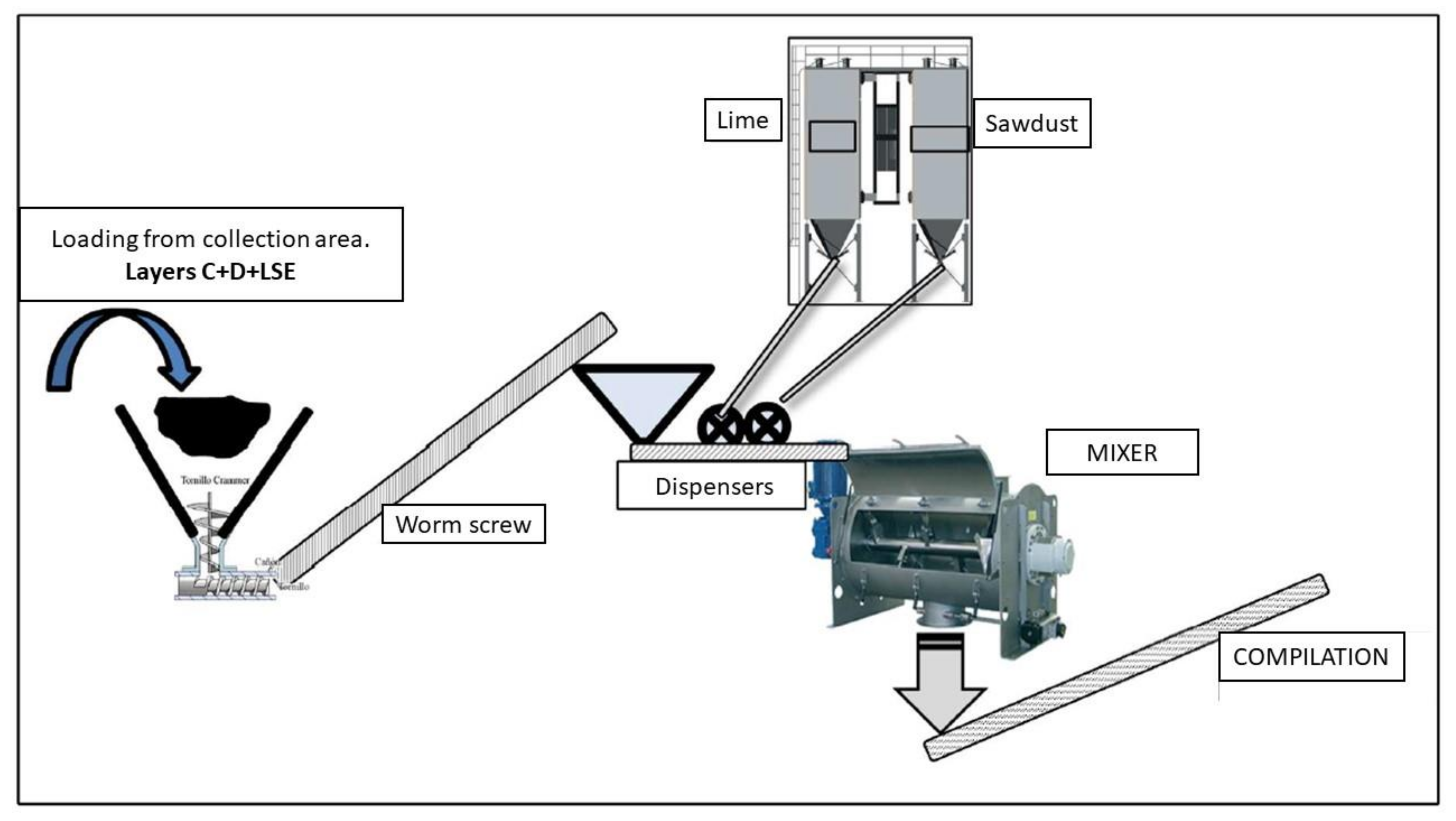
2.4. Waste Treatment
- Highly contaminated and acidic water.
- Semisolid viscosity through all of the settling pond.
- Highly corrosive material with a very low pH.
- Organic and inorganic vapour emissions.
2.5. Environmental Specifications in the Cement Sector
2.6. Energy Balance
2.7. CO2 Emissions
3. Results
3.1. Energy Balance: Waste Fuel
3.2. Energy Balance: Waste Incineration
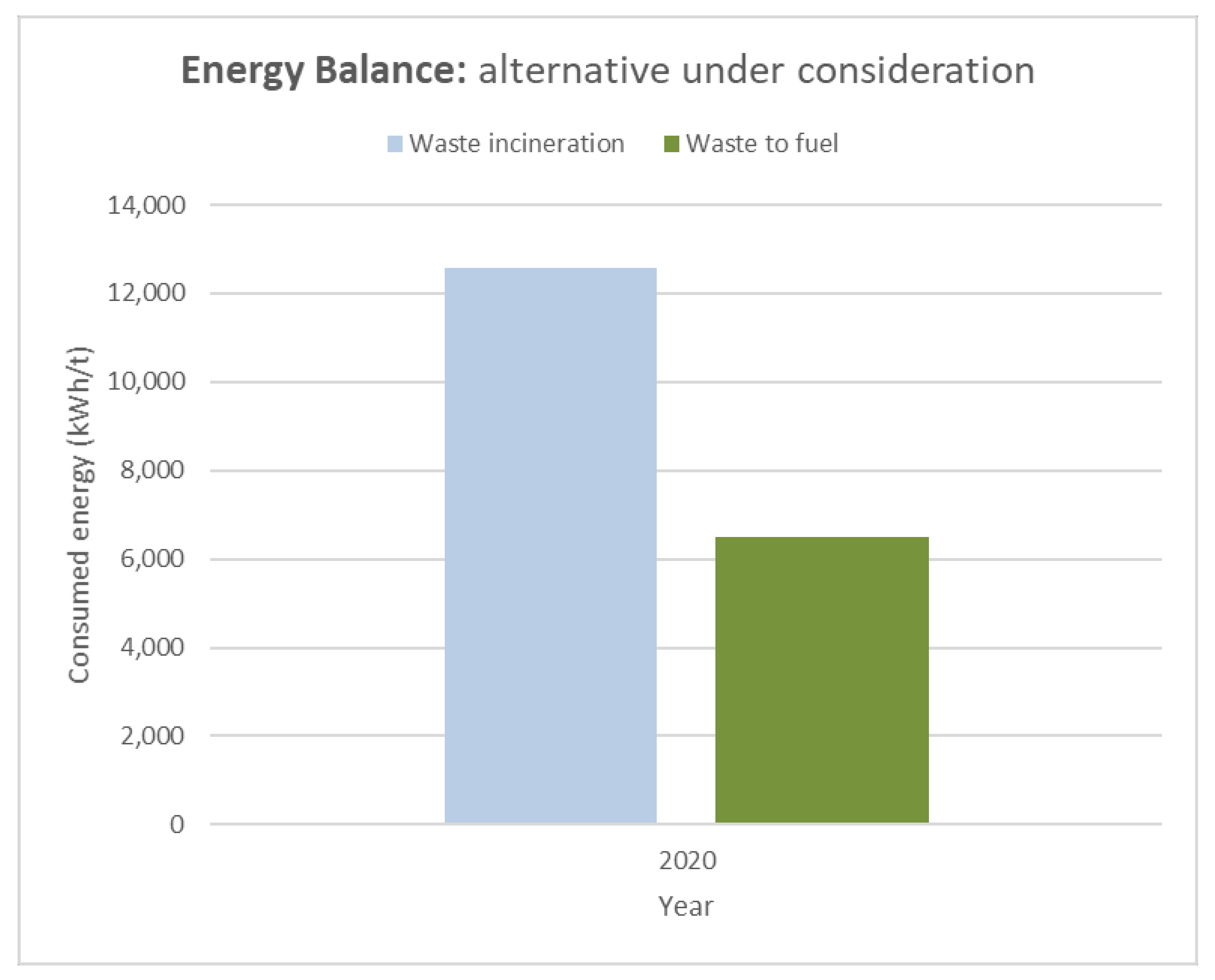
3.3. Comparison of the Two Case Studies: Energy Recovery vs. Incineration
3.4. CO2 Emissions
4. Conclusions
Author Contributions
Funding
Institutional Review Board Statement
Informed Consent Statement
Data Availability Statement
Acknowledgments
Conflicts of Interest
References
- Bolaños, V.H.; Ortega, F.; Reyes, D. Dossier Medio Ambiente, Ciencia y Sociedad. Andamios 2015, 12, 7–14. [Google Scholar]
- Schulz, C.; Whitney, B.S.; Rossetto, O.C.; Neves, D.M.; Crabb, L.; de Oliveira, E.C.; Lima, P.L.T.; Afzal, M.; Laing, A.F.; Fernandes, L.C.D.S.; et al. Physical ecological and human dimensions of environmental change in Brazil’s Pantanal wetland: Synthesis and research agenda. Sci. Total Environ. 2019, 687, 1011–1027. [Google Scholar] [CrossRef]
- OECD. Towards a Circular Economy: A Zero Waste Programme for Europe. Available online: https://www.oecd.org/env/outreach/EC-Circular-econonomy.pdf (accessed on 17 May 2021).
- Prieto-Sandoval, V.; Jaca, C.; Ormazabal, M. Towards a consensus on the circular economy. J. Clean. Prod. 2017, 179, 605–615. [Google Scholar] [CrossRef]
- Rosa, P.; Sassanelli, C.; Urbinati, A.; Chiaroni, D.; Terzi, S. Assessing relations between Circular Economy and Industry 4.0: A systematic literature review. Int. J. Prod. Res. 2020, 58, 1662–1687. [Google Scholar] [CrossRef] [Green Version]
- Cohen-Rosenthal, E. A walk on the human side of industrial ecology. Am. Behav. Sci. 2000, 44, 245–264. [Google Scholar] [CrossRef]
- Severiche, C.A.; Acevedo, R.L. Biogás a partir de residuos orgánicos y su apuesta como combustibles de segunda generación. Rev. Fac. Ing. 2013, 14, 6–15. [Google Scholar] [CrossRef]
- Romero, A. Aprovechamiento de la biomasa como fuente de energía alternativa a los combustibles fósiles. Rev. R. Acad. Cien. Exact Fis. Nat. 2010, 104, 331–345. [Google Scholar]
- Aguilar-Virgen, Q.; Armijo-de Vega, C.; Taboada-González, P.; Aguilar, X.M. Potencial de recuperación de residuos sólidos domésticos dispuestos en un relleno sanitario. Rev. Ing. 2010, 32, 16–27. [Google Scholar] [CrossRef]
- Arner, A.; Barberán, R.; Mur, J. La política de gestión de residuos: Los aceites usados. Rev. Econ. Apl. 2006, 42, 81–100. [Google Scholar]
- Fong, W.; Quiñonez, E.; Tejada, C. Caracterización físico-química de aceites usados de motores para su reciclaje. Prospectiva 2017, 15, 135–144. [Google Scholar]
- Bhaskar, T.; Uddin, A.; Muto, A.; Sakata, Y.; Omura, Y.; Kimura, K.; Kawakami, Y. Recycling of waste lubricant oil into chemical feedstock or fuel oil over supported iron oxide catalysts. Fuel 2004, 83, 9–15. [Google Scholar] [CrossRef]
- Medina-Mijangos, R.; Seguí-Amórtegui, L. Technical-economic analysis of a municipal solid waste energy recovery facility in Spain: A case study. Waste Manag. 2021, 119, 254–266. [Google Scholar] [CrossRef]
- Puertas, E.; Blanco-Valera, M.T. Empleo de combustibles alternativos en la fabricación de cemento. Efecto en las características y propiedades de los clínkeres y cementos. Mater. Construc. 2004, 54, 51–64. [Google Scholar] [CrossRef]
- Abdallah, R.; Juaidi, A.; Assad, M.; Salameh, T.; Manzano-Agugliaro, F. Energy Recovery from Waste Tires Using Pyrolysis: Palestine as Case of Study. Energies 2020, 13, 1817. [Google Scholar] [CrossRef] [Green Version]
- The Development of a National Master Plan for Hazardous Waste Management for the Palestinian National Authority. Available online: http://environment.pna.ps/ar/files/Part_one_Final_Report_on_The_Development_of_a_National_Master_Plan_for_Hazardous_Waste_Management_for_the_Palestinian_National_Authority_en.pdf (accessed on 17 May 2021).
- Sakata, Y.; Bhasker, T.; Uddin, M.A.; Muto, A.; Matsui, T. Development of a catalytic dehalogenation (Cl, Br) process for municipal. J. Mater. Cycles Waste Manag. 2003, 5, 113–124. [Google Scholar] [CrossRef]
- Lopez, A.; Blanco, F.; Gutierrez, M. Mejora del rendimiento de una cementera mediante el empleo de combustibles alternativos. Rev. Electrónica Medioambiente 2012, 12, 47–61. [Google Scholar] [CrossRef] [Green Version]
- Elkhadiri, I.; Diouri, A.; Boukhari, A.; Puertas, F.; Vázquez, T. Obtención de cementos belíticos de sulfonaluminatos a partir de residuos industriales. Mater. Construc. 2003, 53, 57–69. [Google Scholar]
- Guzmán, L.; de la Hoz, D.; Pfaffenbichler, P.; Shepherd, S. Impact of fuel consumption taxes on mobility patterns and CO2 emissions using a system dynamic approach. In Proceedings of the 10th International Conference on Application of Advanced Technologies in Transportation, Athens, Greece, 27–31 May 2008. [Google Scholar]
- Barredo, I.; Casla, M. Biocombustibles, una industria en transición. DYNA Ing. Ind. 2012, 87, 31–34. [Google Scholar]
- Council Decision of 25 April 2002 Concerning the Approval, on Behalf of the European Community, of the Kyoto Protocol to the United Nations Framework Convention on Climate Change and the Joint Fulfilment of Commitments Thereunder. Available online: https://eur-lex.europa.eu/legal-content/EN/TXT/?uri=celex%3A32002D0358 (accessed on 8 June 2021).
- O´Mahony, T.; Zhou, P.; Sweeney, J. The driving forces of change in energy-related CO2 emissions in Ireland: A multi-sectoral decomposition from 1990 to 2007. Energy Policy 2012, 44, 256–267. [Google Scholar] [CrossRef] [Green Version]
- Grubb, M. Technology innovation and climate change polity: An overview of issues and options. Keio Econ. Stud. 2004, 41, 103–132. [Google Scholar]
- Valorización Ambiental y Caracterización de los Ecosistemas Acuáticos Leníticos del Parque Regional en Torno a los Ejes de los Cursos Bajos de los Ríos Manzanares y Jarama. Available online: https://www.researchgate.net/publication/297387060_Valoracion_ambiental_y_caracterizacion_de_los_ecosistemas_acuaticos_leniticos_del_Parque_Regional_en_torno_a_los_ejes_de_los_cursos_bajos_de_los_rios_Manzanares_y_Jarama (accessed on 8 June 2021).
- Carreño, F.; García, S.; Lillo, J.; Fernández, R.; Mabeth-Montoya, A. Building a 3D geomodel for water resources management: Case study in the Regional Park of the lower courses of Manzanares and Jarama Rivers (Madrid, Spain). Environ. Earth Sci. 2013, 71, 61–66. [Google Scholar] [CrossRef]
- Panera, J.; Torres, T.; Pérez-González, A.; Ortiz, J.E.; Rubio-Jara, S.; Del Val, D.U. Geocronología de la Terraza Compleja de Arganda en el valle del río Jarama (Madrid, España). Estud. Geol. 2011, 67, 495. [Google Scholar] [CrossRef] [Green Version]
- Mora, P.; Barettino, D.; Ponce, A.; Sánchez-Martín, L.; Llamas, B. Waste-to-Energy Process to Recover Dangerous Pollutants in an Environmental Protected Area. Appl. Sci. 2021, 11, 1324. [Google Scholar] [CrossRef]
- Block, C.; Van, J.; Van, A.; Wauters, G.; Vandecasteele, C. Incineration of Hazardous Waste: A Sustainable Process? Waste Biomass Valorization 2015, 6, 137–145. [Google Scholar] [CrossRef]
- Rivera-Austrui, J.; Martinez, K.; Abad, E.; Rivera, J. El control de emisiones de contaminantes persistentes en la utilización de combustibles alternativos en la industria del cemento. Rev. Técnica Cem. Hormigón 2010, 939, 74–81. [Google Scholar]
- Directive 2000/76/EC of the European Parliament and of the Council of 4 December 2000 on the Incineration of Waste. Available online: https://eur-lex.europa.eu/legal-content/ES/ALL/?uri=celex%3A32000L0076 (accessed on 8 June 2021).
- Real Decreto 508/2007, de 20 de Abril, por el que se Regula el Suministro de Información sobre Emisiones del Reglamento E-PRTR y de las Autoridades Ambientales Integradas. Available online: https://www.boe.es/buscar/doc.php?id=BOE-A-2007-8351 (accessed on 9 June 2021).
- Real Decreto 815/2013, de 18 de Octubre, por el que se Aprueba el Reglamento de Emisiones Industriales y de Desarrollo de la Ley 16/2002, de 1 de Junio, de Prevención y Control Integrados de la Contaminación. Available online: https://www.boe.es/buscar/doc.php?id=BOE-A-2013-10949 (accessed on 9 June 2021).
- Worell, E.; Price, L.; Martin, N.; Hendriks, C.; Meida, L. Carbon dioxide emissions from the global cement industry. Ann. Rev. Environ. Resour. 2001, 26, 303–329. [Google Scholar] [CrossRef]
- Hanle, L. Understanding CO2 emissions. Word Cement 2006, 37, 69–72. [Google Scholar]
- Ministerio para la Transición Ecológica y el Reto Demográfico. Factores de Emisión: Registro de Huella de Carbono, Compensación y Proyectos de Absorción de Dióxido de Carbono. Available online: https://www.miteco.gob.es/es/cambio-climatico/temas/mitigacion-politicas-y-medidas/factoresemision_tcm30-479095.pdf (accessed on 9 June 2021).
- Guía Práctica para el Cálculo de Emisiones de Gases de Efecto Invernadero (GEI). Available online: https://canviclimatic.gencat.cat/es/detalls/Article/Guia-de-calcul-demissions-de-GEI (accessed on 9 June 2021).
- Fabricación de Cemento (Combustión). Available online: https://www.miteco.gob.es/es/calidad-y-evaluacion-ambiental/temas/sistema-espanol-de-inventario-sei-/030311-combust-fabric-cemento_tcm30-430164.pdf (accessed on 9 June 2021).

| Units | D Layer | Sureste Ponds | |
|---|---|---|---|
| Volume | m3 | 4238 | 10,200 |
| Density | Kg/m3 | 1379.80 | 1074.60 |
| Weight | T | 5848 | 10,961 |
| Viscosity | cP | 304,872.29 | |
| Water | % | 7.1 | 19.03 |
| T | 157 | 536 | |
| Volatile matter | % | 13.65 | 63.67 |
| Ash content at 815 °C | % | 51.30 | 4.85 |
| Gross Calorific Value | Kcal/Kg | 4030.52 | 6698.95 |
| Net Calorific Value | Kcal/Kg | 3517 | 6285 |
| pH | 6.20 | <1 | |
| Total cyanides | mg/Kg | 0.69 | |
| Acidity | mg KOH/g | 25.7 | 184.80 |
| t KOH | 57 | ||
| Sulphur | % | 3.09 | 8.61 |
| T | 68.2 | 942 | |
| Chlorine | % | 0.02 | 0.05 |
| Flash point | °C | >100 | 243 |
| PAHs | |||
| Sum 16 PAHS | mg/Kg | 28.87 | 34.27 |
| PCBs UNE 12766 | |||
| Sum PCB 7 | mg/Kg | 10.03 | 13.85 |
| PCBs UNE 61619 | |||
| Sum PCB | mg/Kg | 10.3 | 45.93 |
| Metals | |||
| Vanadium (V) | mg/Kg | 2.67 | 0.89 |
| Chromium (Cr) | mg/Kg | 15.25 | 9.47 |
| Cobalt (Co) | mg/Kg | 0.69 | |
| Nickel (Ni) | mg/Kg | 1.50 | 5.33 |
| Copper (Cu) | mg/Kg | 37.75 | 47.08 |
| Zinc (Zn) | mg/Kg | 440 | 1702.5 |
| Arsenic (As) | mg/Kg | 2.77 | 1.03 |
| Molybdenum (Mo) | mg/Kg | 5.33 | 9.78 |
| Cadmium (Cd) | mg/Kg | 0.3 | |
| Tin (Sn) | mg/Kg | 7.33 | 3.88 |
| Barium (Ba) | mg/Kg | 316.67 | 66.88 |
| Lead (Pb) | mg/Kg | 4757.5 | 4275 |
| Mercury (Hg) | mg/Kg | 1.70 | 0.38 |
| 2020–2021 | |
|---|---|
| Weight of waste (t) | 16,809 |
| Heat of combustion (Kcal/Kg) | 5336.51 |
| kWh/twaste | 2020–2021 |
|---|---|
| Egross | 6206.36 |
| kWh/twaste | 2020–2021 |
|---|---|
| Eextraction | 14.34 |
| Etreatment1 | 0.38 |
| Etreatment2 | 1.92 |
| kWh/twaste | 2020–2021 |
|---|---|
| Ponds–Albox | 129.28 |
| Albox–Carboneras | 12.93 |
| Carboneras | 142.21 |
| Ponds-Arganda | 2.59 |
| Arganda-Oural | 136.26 |
| Oural | 138.85 |
| kWh/twaste | 2020–2021 |
|---|---|
| Carboneras | 6365.20 |
| Oural | 6361.84 |
| kWh/twaste | 2020–2021 |
|---|---|
| Egross | 6206.36 |
| Eextraction | 14.34 |
| Etreatment | 0.38 |
| Etransport | 137.04 |
| Tonnes of CO2 | Total |
|---|---|
| Extraction | 57.59 |
| Treatment in situ | 1.14 |
| Treatment centre | 5.85 |
| Transport 1 | 333.46 |
| Transport 2 | 325.58 |
| Petroleum coke equivalent | 37,293.29 |
Publisher’s Note: MDPI stays neutral with regard to jurisdictional claims in published maps and institutional affiliations. |
© 2022 by the authors. Licensee MDPI, Basel, Switzerland. This article is an open access article distributed under the terms and conditions of the Creative Commons Attribution (CC BY) license (https://creativecommons.org/licenses/by/4.0/).
Share and Cite
Mora, P.; Barettino, D.; Ponce, A.; Sánchez-Martín, L.; Llamas, B. Alternative Fuel Generation from Dangerous Solid Waste in a Protected Environmental Area. Energies 2022, 15, 659. https://doi.org/10.3390/en15020659
Mora P, Barettino D, Ponce A, Sánchez-Martín L, Llamas B. Alternative Fuel Generation from Dangerous Solid Waste in a Protected Environmental Area. Energies. 2022; 15(2):659. https://doi.org/10.3390/en15020659
Chicago/Turabian StyleMora, Pedro, Daniel Barettino, Antonio Ponce, Laura Sánchez-Martín, and Bernardo Llamas. 2022. "Alternative Fuel Generation from Dangerous Solid Waste in a Protected Environmental Area" Energies 15, no. 2: 659. https://doi.org/10.3390/en15020659
APA StyleMora, P., Barettino, D., Ponce, A., Sánchez-Martín, L., & Llamas, B. (2022). Alternative Fuel Generation from Dangerous Solid Waste in a Protected Environmental Area. Energies, 15(2), 659. https://doi.org/10.3390/en15020659