1. Introduction
Fibre optic cables are commonly used at Nuclear Power Plants (NPPs) in I&C systems but they are usually used outside of containment areas and in mild environments. For example, the Czech NPP Dukovany, a Pressurized Water Reactor (PWR) type with four 440 MW units, has almost 1500 optical cables installed with a total length of 150 km. All the optic cables are situated in areas outside radiation zones. Nevertheless, currently there is a requirement to use optic cables in NPP containment areas, which means in locations with radiation. The values of radiation dose rate depend on the location within the NPP containment. It may vary from almost nothing up to 1 Gy/h near the steam generator or main circulating line [
1] which gives a total radiation dose of up to 350 kGy during a 40-year lifetime. Hence, it is very important to know where the cables are expected to be installed, at which level of radiation and what the expected service lifetime is forecasted to be.
The application of fibre optic cables on systems important to the safety in NPPs requires their qualification. For this reason, the international standard for qualification IEEE 1682 [
2] has existed since 2011. The qualification process (demonstration that the equipment is able to function within its required accuracy and performance requirements in all required operational and environmental conditions [
2,
3]) is described in our previous paper [
4] and is briefly summarized in
Section 2.
Radiation is the most significant environmental stressor in a NPP environment for optical fibres [
2,
4], which causes fibre darkening, i.e., a dramatic optical attenuation increase and a loss of functionality. Radiation leads to the formation of colour centres in the glass structures [
5,
6,
7,
8,
9,
10,
11], which cause a change in the absorption characteristics leading to the colouration of the fibre. This effect is so significant that it can lead to the “blinding” of an optical fibre with attenuations in tens of dB per km depending on the radiation dose. This Radiation-Induced Attenuation (RIA) phenomenon is caused by the generation through ionization or displacement damages of point defects in both silica-based fibre core and fluorine-doped cladding [
8]. After the irradiation has stopped, glass fibre goes through a “recovery process” (otherwise relaxation) [
2,
12], when the glass becomes transparent again, i.e., attenuation decreases [
10,
13]. However, this process is not completely reversible. The extent of recovery can be affected, among others, by time and temperature after the radiation ageing. It was previously shown that the optical losses of the fibres are heavily dependent upon dopants and defects in the optical fibres. Therefore, different fibre compositions will be affected differently [
14].
UJV Rez a.s. testing laboratory has qualified two types of optic cables with different fibres for the installation in NPPs. Results concerning the ionizing radiation are as follows:
Simplex and breakout cables with multi-mode (MM) fibres increased their attenuation during irradiation. Nevertheless, during the next 30 days of the recovery process, the attenuation continuously decreased as expected [
4]. The trend is displayed in
Figure 1 on the blue line “Expected attenuation recovery”.
The fibre used was a MM 62.5/125, J-fiber, radiation-hardened fibre, MIL-PRF-49291/6C. The Simplex cable consisted of fibre, buffer, aramid yarn and cord. The breakout cable consisted of 24 simplex cables, a central strength member, PE tapes, additional aramid yarn and an outer jacket. The initial measured values of attenuation were 1 dB/km at 1300 nm, and the highest measured value after irradiation with a dose of 55 kGy was 40 dB/km.
The situation for gel-filled loose tube single-mode (SM) cables was quite different. Attenuation decreased (recovered) a few days after the irradiation. After this short period, the trend changed and attenuation increased to a value well above the attenuation just after the irradiation; see red line in
Figure 1.
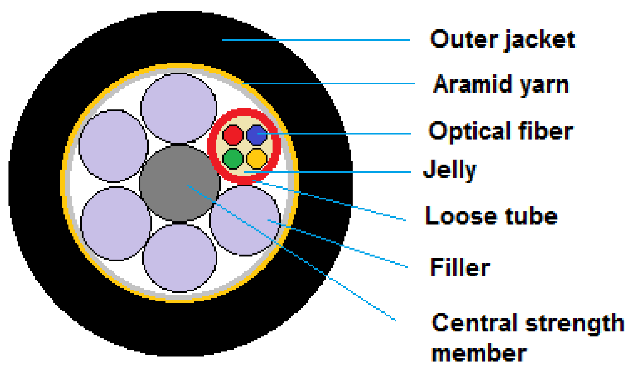
The fibre used was a SM 9/125 μm, ITU-T G.652, J-fiber, radiation hardened fibre. The construction of the cable is shown in
Figure 2. The initial measured values of attenuation were 0.4 dB/km at 1310 nm, and the highest measured value just after irradiation with a dose of 55 kGy was 51 dB/km. During the following process, when we expected to observe signs of recovery, the attenuation increased up to 146 dB/km. Similar values were also measured at 1550 nm.
This atypical recovery behaviour was observed only on loose tube cables with SM fibres placed in tubes. Two kinds of this cable construction were tested—the small one contained only four fibres in one tube while the other cable contained 12 tubes with 12 fibres per tube. The gel was used as a waterproof barrier in the cable tubes, as depicted in
Figure 2.
Such high attenuation values disqualify these SM fibres for use in NPP containment environments. Therefore, additional experiments were performed trying to explain the reasons for such an unexpected behaviour.
2. Methodology
To understand tests which are performed, the qualification process for nuclear power plants applications according to the standard [
2] is briefly described. The text is partially taken from our previous paper [
4] which has been repeated here for a better understanding of the presented results. Basically, all of the stressors causing age-related degradation need to be simulated. The required procedure to qualify fibre optic cables is as follows:
- -
Accelerated thermal ageing simulates the long-term operation at elevated temperatures.
- -
Accelerated radiation ageing simulates the stress encountered from the influence of ionizing radiation during operation.
- -
Simulation of mechanical stress.
- -
Simulation of accident conditions.
- -
Throughout the qualification, functional properties shall be monitored. The most important property is attenuation.
Only the irradiation was described in this paper because it is the most important factor which influences fibre optic cable attenuation [
2,
4].
2.1. Irradiation
The radiation ageing was simulated by irradiation at room temperature and at atmospheric pressure with a
60Co gamma–ray source with a dose rate higher than what would normally be found in a real environment. The dose was determined by alanine/ESR dosimetry and stated as dose in Si [
15]. During irradiation, the samples were coiled on a perforated stainless-steel cylinder with a diameter of 0.4–0.8 m, while the cobalt source was in the middle of the cylinder. The energy of the gamma photons/rays from the
60Co were 1.17 and 1.33 MeV, respectively. The fibre optic cables which were tested did not have any metal parts. Thus, the total dose was homogeneously distributed within the whole sample. Cable ends with connections were placed in a position with a much lower dose rate or they were shielded. For an easier survey, only mean values of total dose and dose rates are provided, without uncertainties. After irradiation, the cables were straightened and coiled at least once at the in-service minimum bend radius of the cable, which was for the cables being tested, 20 × cable diameter (20D). Such mechanical stress is required by the standard IEEE 1682 [
2]. However, bending was not applied in additional experiments.
Total doses were between 10 and 50 kGy and represent expected operational doses of the possible fibre optic cable installation in a respective NPP. Applied doses and dose rates are mentioned in the text below.
2.2. Attenuation Measurement
To measure attenuation with a reasonable rate of uncertainty, the optical route should be at least 100 m long. To increase the optical length of the cable, individual fibres within the cable can be connected to a series by fusion splicing. Nevertheless, it must be ensured that these fusions and connections do not influence the results.
MM cables were measured at wavelengths 850 nm and 1300 nm, and SM cables at 1310 nm and 1550 nm (in a few cases at 1625 nm). Differences in results were discussed in the previous paper [
4] and are insignificant. Therefore, in this paper, only the results at the wavelength 1550 nm are shown.
During the experiments, we used two attenuation-measuring methods:
Attenuation was measured before irradiation, in some cases during the irradiation, just after the irradiation and then during the following 30 days when the samples were stored at room temperature. The measuring devices were connected to the tested samples during the 30 days of the recovery process and could not be easily used for another experiment. Therefore, only a limited number of experiments was performed and some of our conclusions were not proven on more samples. The main goal was to find the causes of the inverse recovery process.
Measuring the attenuation was performed discretely, i.e., in specific intervals or continuously to monitor its trend. In the case of discrete measurement, the equipment was connected/disconnected, which caused imperfect results.
3. Experimental Plan
In the previous work [
4], the experiments mainly verified the individual steps of the qualification to exclude the probability of mistakes during the qualification process. The summarization list of the experiments performed and their results are as follows:
• Influence of connector and fusions irradiation
To check the possible influence of connectors and fusion splicing, the same samples were irradiated in such a way that the ends of the cable were shielded and/or pulled out of the irradiation facility. There was no difference between the ends with connectors that were pulled out (i.e., not irradiated) or were slightly irradiated which was the case from previous testing.
• SM fibres with different dopants
In this experiment, we tested only the fibre samples to check the role of Ge dopants on the inverse recovery process. We found that the dopants used did not have any effect on radiation-resistant fibres (two types were tested) and there is no increase in attenuation during the recovery process if only the fibres alone are irradiated.
• Thermal ageing
The first step of qualification is a simulation of long-term thermal ageing. In accordance with the standard [
2], thermal ageing is simulated using the Arrhenius approach, which assumes that a short-term simulation of thermal ageing at higher temperatures causes the same degradation as long-term ageing at lower temperatures. To check the possible influence of thermal ageing, the cable was irradiated also without any thermal pre-treatment. Both cables, thermally aged as well as without thermal treatment, exhibited the same inverse recovery process.
• Mechanical stress after irradiation
Mechanical stress is caused by straightening and bending immediately after the irradiation. Such a procedure is required by the standard and simulates possible mechanical stresses encountered in the operation of an NPP and during some accidents that may occur. Therefore, cables coiled around a mandrel after irradiation as well as samples without mechanical stress were measured during the recovery process. There was no difference; i.e., the mechanical stress is not the reason for the inverse recovery behaviour.
• Dose rate effect
The cable and fibre were irradiated alone at a dose rate of 1.45 kGy/h and compared with the cable and fibre sample irradiated at 0.0173 kGy/h, i.e., approx. 100 times lower dose rate. The total dose was around 15 kGy. The attenuation increasing during and after irradiation was approximately two times higher when the whole cable was irradiated compared to when the fibre was irradiated on its own. The inverse recovery effect (in the case of cables) was much higher when irradiated at a higher dose rate.
The experiments presented did not explain the nature of the inverse recovery process. Nevertheless, we could exclude that the inverse recovery process is associated with some necessary procedure during the qualification process. Based on our results, we can also state that this phenomenon is not caused by the fibreglass material itself because when the fibres were irradiated on their own, the inverse recovery process did not appear. The next set of experiments described in this paper was focused on studying the possible effect of total radiation dose and the differences in cable construction.
4. Results and Discussion
The cable which was found to have the inverse recovery process is a gel-filled loose tube SM cable. Hence, we checked the potential influence and interaction of the material surrounding the fibre, i.e., the coating on the fibre, gel and the loose tube.
4.1. Influence of the Coating
To test any possible interactions between the coating and the SM fibre itself, a few fibre samples with different coating colours (red and blue) were tested.
Both red and blue samples were irradiated with a total dose of 15 kGy. The attenuation decrease after the irradiation was the same for both samples. The coating did not affect the inverse recovery process.
4.2. Influence of the Loose Tube and Number of Fibres in the Tube
Cables with the same construction as shown in
Figure 2 with gel-filled Polybutylene Terephthalate (PBT) tubes manufactured by two different suppliers were tested. One tube had a partially porous wall, while the second one was without any defects (
Figure 3a,b).
In addition, two cable dimensions of porous tube cable were parallelly tested. One cable was with four fibres inside the loose tube and one cable with 12 fibres per tube with almost the same diameter. After the irradiation with a dose of 17.4 kGy and a dose rate 0.60 kGy/h, the sample with only four fibres exhibited a stronger inverse recovery behaviour (see
Figure 4).
Summary of the tube influence:
Two PBT loose tubes manufactured by different suppliers were tested. One “imperfect” tube had pores in the wall, while the second one was more homogeneous. Both samples were accounted for in the inverse recovery process. This suggests that the mechanism responsible for the investigated inverse recovery process is due to the gel.
When the same type of gel-filled loose tubes with 12 fibres and with only four fibres were irradiated, the attenuation line during inverse recovery was not identical. The cable sample with only four fibres inside the tube showed a stronger inverse effect. The effect shows again that the gel may be the main reason for the inverse recovery process. The amount of gel in the tube with four fibres was much more than in the tube with 12 fibres.
4.3. Influence of the Gel
The above-mentioned experiments indicate that the component causing the inverse recovery is the gel. To prove this, we tested cables with porous tubes with gel inside (4 and 12 fibres) and without gel (dry type non-porous tube cable, with four fibres in a tube). After irradiation with a dose of 17.4 kGy and a dose rate of 0.60 kGy/h, the attenuation started to decrease. In the case of the dry type, once the irradiation stopped, the attenuation continuously decreased while the samples with gel exhibited an inverse recovery process (
Figure 4). To exclude the possibility of a local defect, OTDR measurements were performed. They did not indicate any local disturbances within the measured path. The attenuation had the same homogeneous level within the length of the entire fibre.
Based on all these results, we can clearly state that the component responsible for the inverse recovery process is the gel.
The Shanghai Honghui Optic Communication Tech produces gel under the name LT-600. The exact chemical composition is unknown. Information from the material safety data sheet is the following: mineral oil 93%, thermoplastic rubber 6.3%, anti-oxidant, polyethylene 0.7%.
There are a few hypotheses on how a gel can influence or cause an inverse attenuation effect after irradiation. Some of them are as follows:
- -
Gel expands its volume due to gaseous radiolytic product formation, inner cross-linking and chemical reactions in the gel, resulting in mechanical stress.
- -
Gel may shrink which results in mechanical stress.
- -
Radiolytic products react with the fibre’s coating or diffuse into the glass.
To test the hypotheses about the stress due to volume increase/decrease, we irradiated two samples: a non-treated loose tube and a perforated sample enabling gel to leak. In approximately 20 cm distances, the loose tube was perforated by a fibre optic buffer stripper. In the places of perforation, a small outflow of gel was observed. Continuity of the optical route was controlled before irradiation by OTDR, to ensure that there was no route interruption caused by stripping. However, this simple experiment did not show any improvement in the inverse recovery process.
A possible explanation is that radiation creates hydrogen species that are able to diffuse from the gel through the fibre coating up to the fibre core, interacting with created point defects (such as non-bridging oxygen hole centres Si-O). They can create Si-OH, that are associated with absorption peaks, especially at 1380 nm [
8]. The delay between the irradiation and the observed effects may be explained by the diffusion time of hydrogen species in the fibre. The hydrogen can be, on one hand, easily loaded at room temperature in silica-based fibres, but on the other hand, it will also quickly diffuse out. This fact renders the treatment efficiency dependent on the time delay between the treatment and the irradiation [
8,
14].
To check this possibility, SM fibre in the tube with gel was irradiated with a gamma-ray irradiation dose of 1.12 kGy/h for 9 h. The total gamma radiation dose was 10.1 kGy. During irradiation, we measured optical losses at three wavelengths, 1310, 1550 and 1625 nm, using Insertion & Reflection Loss Meter JCIRL-300 with detector Jericore, and the obtained results are shown in
Figure 5a. The measurements show that the optical losses increase with increasing gamma-ray dose and optical losses at 1310 nm are higher than at wavelengths 1550 and 1625 nm. We can observe lower values of the optical losses after 390 min and 450 min (at the wavelength 1310 nm) during the gamma rays’ irradiation. These lower values are caused by how the measurements were taken, which required the connection/disconnection of the applied optical sources and the optical fibres which were measured.
After gamma-ray irradiation was stopped, we measured the optical spectrum. The measurement was done using an optical spectrum analyzer YOKOGAWA AQ6370C in the range from 600 to 1700 nm and we used the optical source HL-2000 FHSA (Ocean Optics) with a typical output power of 8.4 mW. First, we measured optical losses pristine optical fibre before gamma-ray irradiation, then we repeated measurement at 2, 4, 9, 16 and 18 days after irradiation. The results which were obtained are shown in
Figure 5b.
Figure 5b shows an increase in optical losses after irradiation. We observed that 9 days after irradiation, the increase of the optical losses stopped.
Figure 5b also shows that optical losses increased higher at wavelengths around 1380 nm than at other wavelengths. This is due to an increase in the content of hydroxyl groups (Si-OH) at an attenuation peak of 1385 nm and the next reason for this increment of the optical losses could be to acrylate coating due to the radiation induced radiolytic hydrogen from the polymer coating diffusing to the fibre core [
14].
5. Conclusions
When fibre optic cables are exposed to gamma-irradiation, fibre darkening can be caused with an attenuation increase. After the irradiation has stopped, the fibre goes through a recovery process with an attenuation decrease. This effect is widely known and was also proved in the UJV Řež testing laboratory when multi-mode (MM) fibre optic cables were irradiated. However, after single-mode (SM) cable irradiation, the attenuation decreased as expected for only a few days. After this short period of time, attenuation changed dramatically, increasing to a value well above the attenuation just after the irradiation had finished. We call this phenomenon “inverse recovery process”, and it may play a negative role in the use of fibre optic cables in nuclear power plants.
A lot of experiments were performed to find the reason for this effect [
4]. This paper describes an additional set of experiments.
It has been proved that the component responsible for the inverse recovery process is the gel. The main evidence is based on the following results:
- -
Dry loose tube without gel after irradiation goes through continuously healing effects with attenuation recovery, while the same loose tube which contains gel exhibits an inverse recovery process.
- -
Loose tube cable with a larger amount of gel has a much stronger inverse recovery process than a sample of loose tube cable with a smaller amount of gel.
- -
Changing other parameters, like mechanical stress after irradiation, thermal ageing before irradiation, different fibres, different coatings, total dose and the applied radiation dose rate had no effect on the recovery process.
Some hypotheses on how the gel may influence the recovery are suggested below:
- -
Gel expands its volume due to gaseous radiolytic products forming, inner cross-linking and chemical reactions in the gel, resulting in mechanical stress.
- -
Gel may shrink which results in mechanical stress.
- -
Radiolytic products react with the fibre coating or diffuse into the glass.
A comparative experiment with fibres suspended in gel in a high-quality tube (
Figure 3b) and in a perforated tube enabling the gel to leak was performed. The presence or absence of mechanical stress did not show any of the inverse recovery processes.
A possible explanation is that radiation creates hydrogen species, slowly diffusing from the gel through the fibre coating up to the fibre core and creating Si-OH, which are associated with absorption at 1385 nm. The presented work is more or less experimental in nature with the main goal to explain the reasons for the inverse recovery process and for fibre optic cables to be safely installed within nuclear power plant containment systems. Additional experiments studying the gel performance under irradiation, hydrogen detection and other radiolytic products detection are planned. These additional experiments will be supported by theoretical investigations concerning hydrogen species diffusion.
Author Contributions
Z.Š., V.P. (Vít Plaček) and V.P. (Václav Prajzler) conceived and designed the experiments; K.M. and P.H. performed the experiments; Z.Š., V.P. (Vít Plaček) and V.P. (Václav Prajzler) analyzed the data and wrote the paper. All authors have read and agreed to the published version of the manuscript.
Funding
Our research has been supported by the Czech Technical University in Prague with the SGS program (SGS20/175/OHK3/3T/13) and Centre of Advanced Applied Natural Sciences”, Reg. No. CZ.02.1.01/0.0/0.0/16_019/0000778, supported by the Operational Program Research, Development and Education, co-financed by the European Structural and Investment Funds and the state budget of the Czech Republic.
Institutional Review Board Statement
Not applicable.
Informed Consent Statement
Not applicable.
Data Availability Statement
The data that support the findings of this study are available from the corresponding author upon reasonable request.
Acknowledgments
Test samples were kindly provided by GOC Co., Ltd. (Fibre optic cable manufacturing company, Gwangju, Korea). Special thanks to colleagues from VŠB (Technical University of Ostrava, Faculty of Electrical Engineering and Computer Science, Department of Telecommunications) for the initial cooperation and measurement.
Conflicts of Interest
The authors declare no conflict of interest.
References
- Anonymous. Technical Basis for Commendable Practices on Ageing Management—SCC and Cable Ageing Project (SCAP), Final Report; NEA/CSNI/R(2010)5; OECD Nuclear Energy Agency: Paris, France, 2010. [Google Scholar]
- IEEE 1682-2011Standard for Qualifying Fiber Optic Cables, Connections, and Optical Fiber Splices for use in Safety Systems in Nuclear Power Generating Stations, IEEE: Piscataway, NJ, USA, 2013.
- No. SSG-69Equipment Qualification for Nuclear Installations; IAEA Safety Standards, Specific Safety Guide, IAEA: Vienna, Austria, 2021.
- Konečná, Z.; Plaček, V.; Havránek, P. Unusual Attenuation Recovery Process after Fiber Optic Cable Irradiation. IOP Conf. Ser. Mater. Sci. Eng. 2017, 266, 012005. [Google Scholar] [CrossRef]
- Morana, A.; Girard, S.; Cannas, M.; Marin, E.; Marcandella, C.; Paillet, P.; Périsse, J.; Macé, J.-R.; Boscaino, R.; Nacir, B.; et al. Influence of neutron and gamma-ray irradiations on rad-hard optical fiber. Opt. Mater. Express 2015, 5, 898–911. [Google Scholar] [CrossRef]
- Sandhu, A.K.; Singh, S.; Pandey, O.P. Gamma ray induced modifications of quaternary silicate glasses. J. Phys. D Appl. Phys. 2008, 41, 165402. [Google Scholar] [CrossRef]
- Girard, S.; Richard, N.; Ouerdane, Y.; Origlio, G.; Boukenter, A.; Martin-Samos, L.; Paillet, P.; Meunier, J.-P.; Baggio, J.; Cannas, M.; et al. Radiation Effects on Silica-Based Preforms and Optical Fibers-II: Coupling Ab initio Simulations and Experiments. IEEE Trans. Nucl. Sci. 2008, 55, 3508–3514. [Google Scholar]
- Campanella, C.; De Michele, V.; Morana, A.; Mélin, G.; Robin, T.; Marin, E.; Ouerdane, Y.; Boukenter, A.; Girard, S. Radiation Effects on Pure-Silica Multimode Optical Fibers in the Visible and Near-Infrared Domains: Influence of OH Groups. Appl. Sci. 2021, 11, 2991. [Google Scholar] [CrossRef]
- London, Y.; Sharma, K.; Diamandi, H.H.; Hen, M.; Bashan, G.; Zehavi, E.; Zilberman, S.; Berkovic, G.; Zentner, A.; Mayoni, M.; et al. Opto-Mechanical Fiber Sensing of Gamma Radiation. J. Lightwave Technol. 2021, 39, 6637–6645. [Google Scholar] [CrossRef]
- Esposito, F.; Srivastava, A.; Campopiano, S.; Iadicicco, A. Radiation Effects on Long Period Fiber Gratings: A Review. Sensors 2020, 20, 2729. [Google Scholar] [CrossRef] [PubMed]
- Kashaykin, P.F.; Tomashuk, A.L.; Vasiliev, S.A.; Ignatyev, A.D.; Shaimerdenov, A.A.; Ponkratov, Y.; Kulsartov, T.V.; Kenzhin, Y.A.; Gizatulin, S.K.; Zholdybayev, T.K.; et al. Radiation resistance of single-mode optical fibres with view to in-reactor applications. Nucl. Mater. Energy 2021, 27, 100981. [Google Scholar] [CrossRef]
- Senior, J.M.; Jamro, M.Y. Optical Fiber Communications: Principles and Practice, 3rd ed.; Person Education: London, UK, 2009. [Google Scholar]
- Vašínek., V.; Hájek, L.; Bednárek, L.; Vanderka, A.; Hlavinka, T.; Marcinka, O. Influence of gamma radiation on optical fibers and devices. In Proceedings of the International Conference on Photonics Solutions 2015, Hua Hin, Thailand, 6–8 July 2015. [Google Scholar]
- Stone, J. Interactions of Hydrogen and Deuterium with Silica Optical Fibers: A Review. J. Lightwave Technol. 1987, 5, 712–733. [Google Scholar] [CrossRef]
- ISO/ASTM 51261:2013Practice for Calibration of Routine Dosimetry Systems for Radiation Processing; Confirmation 2018, ISO: Geneva, Switzerland, 2013.
| Publisher’s Note: MDPI stays neutral with regard to jurisdictional claims in published maps and institutional affiliations. |
© 2022 by the authors. Licensee MDPI, Basel, Switzerland. This article is an open access article distributed under the terms and conditions of the Creative Commons Attribution (CC BY) license (https://creativecommons.org/licenses/by/4.0/).


 ,
, 