Article

State Feedback Speed Control with Periodic Disturbances Attenuation for PMSM Drive

by
Łukasz J. Niewiara
1,*,
Rafał Szczepański
1,
Tomasz Tarczewski
1 and
Lech M. Grzesiak
2
1
Institute of Engineering and Technology, Nicolaus Copernicus University, Grudziadzka 5/7, 87-100 Toruń, Poland
2
Institute of Control and Industrial Electronics, Warsaw University of Technology, 75 Koszykowa Street, 00-662 Warsaw, Poland
*
Author to whom correspondence should be addressed.
Energies 2022, 15(2), 587; https://doi.org/10.3390/en15020587
Submission received: 22 November 2021 / Revised: 10 January 2022 / Accepted: 12 January 2022 / Published: 14 January 2022
(This article belongs to the Special Issue Frontiers in Automatic Control in Drives and Power Electronics)

Abstract

:
This paper proposes an auto-tuned constrained state-feedback controller (SFC) to attenuate periodic disturbances present in permanent magnet synchronous (PMSM) motor drives. An online auto-tuning process of SFC has been made using a powerful nature-inspired optimization algorithm—artificial bee colony (ABC)—to achieve high-performance operation of the drive. A novel performance index is proposed to minimize the impact of pulsating torque and obtain smooth-velocity of the drive. The proposed approach is a practical application of classic control theory with novel engineering-tools for improving the operational quality of a PMSM drive system. The obtained results are compared with a classical cascade control structure (CCS) based on proportional-integral (PI) regulators and disturbance observer-based control (DOBC). A detailed time- and frequency-domain analysis has been conducted in respect to periodic disturbances present in a PMSM drive system. Moreover, the robustness of SFC against parameter variations of inductance and resistance has been tested.

1. Introduction

Permanent magnet synchronous motors (PMSMs) are widely used in industry, automotive, and motion control applications [1,2]. They have gained attention due to good dynamic, static, and exploitation properties such as: high-power density, high efficiency, maintenance-free, relatively low noise, superior inertia-to-weight ratio, and fast torque response  [1,2,3,4,5,6]. As a consequence of the above depicted features, PMSM based variable speed drive systems (VSD) have numerous applications in the industry and domestic use [1,2,3].
Despite numerous advantages of PMSM drive systems, some undesired flaws are present, deteriorating the dynamical and static properties of the motion system. The main drawback is the production of pulsating torque, which negatively impacts the angular velocity causing noticeable ripples [2,7]. It is a kind of periodic disturbance caused by current measurement errors (offset- and scaling errors), dead-time effect [2,7,8], cogging effect, and non-sinusoidal distribution of the flux-linkage in the air gap [2,7,9]. Since the measurement accuracy and switching time of power devices are limited, full elimination of this phenomenon is impossible.
Since the produced pulsating torque varies with the angular velocity of the motor, the attenuation of this undesired phenomena becomes a non-trivial issue. High quality operation requires a smooth output velocity, and therefore the reduction of pulsating torque is a key feature. Hence, it has become an important research topic and arouses considerable interests in the scientific literature: [2,7,10,11]. Two approaches are considered in practice—machine design [11] and drive control approach [2,9,10]. The first is based on stator and rotor shape optimization, whereas the second involves the use of active control schemes for attenuation of periodic disturbances present in the system. The optimization of machine construction is focused on design improvements of the motor body structure, i.e., stator and rotor optimization. In [11] an optimization of the rotor is performed by skewing the magnets on the rotor. A relevant disadvantage of the construction improvement is the more complex design, which results in a higher machine cost due to a more complicated manufacturing process. Since the control approach is a more flexible and less costly solution, it has attracted much more attention. Therefore, numerous studies can be found in the scientific literature [2,4,6,7,9,10,12]. For example, in [7] an extended Kalman filter is employed for estimation of the pulsating torque. The signal obtained is used in a feed-forward compensation path and allows for a significant reduction of velocity ripple. This approach requires a relatively complex estimation algorithm, which may be an serious disadvantage in time critical systems, especially for drive systems with high switching frequency.
The limitation of undesired periodic disturbances can be realized by optimization of motor current waveform [13]. This approach allows for cancellation of undesired torque harmonics, which results in smooth angular velocity of the drive. Numerous advanced control schemes have been developed in order to realize this purpose. The conducted scientific literature analysis indicates that model predictive control (MPC) seems to be the most popular structure in the past years [4,6,12]. The selected control signal is obtained using a prediction of selected state variables and on-line optimization of the defined cost function. It is a relatively complex control strategy with a high computational burden. Therefore, its applicability is limited. Another group of methods under considerable attention in the recent years is disturbance/uncertainty estimation and attenuation (DUEA) [2,5,7,14].
The idea of DUEA is based on the introduction of an additional compensation path in the quadrature axis [2]. It contains two subcategories: disturbance observer-based control (DOBC) [9,10] and active disturbance rejection control (ADRC) [5]. Both schemes are based on the most popular control schemes (i.e., field oriented control (FOC) or direct torque control (DTC)), where the compensation signal is obtained from an additional disturbance observer/rejection block. This is a relatively effective strategy, but it requires introduction of additional disturbance estimator/observer and modification of control law. Moreover, its introduction is not a trivial issue, since extended expert knowledge and a proper selection of several parameters, such as gains, digital filers, and overall structure of the observer/estimator, are required [5,10,15]. In the scientific literature numerous types of DUEA are investigated, e.g., angle-based repetitive observer based [10], non-linear disturbance observer based [5], and artificial neural networks based [14], to name a few. The efficiency of mentioned schemes is limited by the bandwidth of the estimator and its computational burden. Moreover, expert-knowledge is necessary for DEUA employment.
In this paper, the attenuation ability of periodic disturbances for a PMSM drive is investigated. Cascade-free constrained control structure is applied for angular velocity control of the motor. A nature-inspired tuning procedure is employed for selection of controller-gains. The SFC does not contain any compensation paths and, therefore, the computational effort of applied SFC-MPAC structure is comparable with classical FOC [1,16]. The combination of advantages of SFC and a powerful optimization technique allows to obtain a smooth velocity response with a desired dynamics without disturbance estimation. To reach this goal, a dedicated performance index has been developed for the tuning procedure. It allows to minimize the impact of periodic disturbances on the angular velocity of the drive. The literature review [2,14,17,18] indicates that no former works related to application of auto-tuned and constrained SFC for attenuation of periodic disturbances in a PMSM drive system have been presented before. The novelty of the proposed solution is the adaptation of a meta-heuristic optimization algorithm for attenuation of periodic disturbances in a PMSM drive system with a state feedback controller. The developed auto-tuning procedure is based on a novel performance index and employs artificial bee colony optimization algorithm. As a result, smooth angular velocity shape and good dynamic properties have been obtained. The proposed control structure may be applied in high performance motion control systems based on PMSMs, i.e., satellite trackers, metal working machine tools, autonomous vehicles and heating, ventilation, and air conditioning systems.

2. Proposed Control System

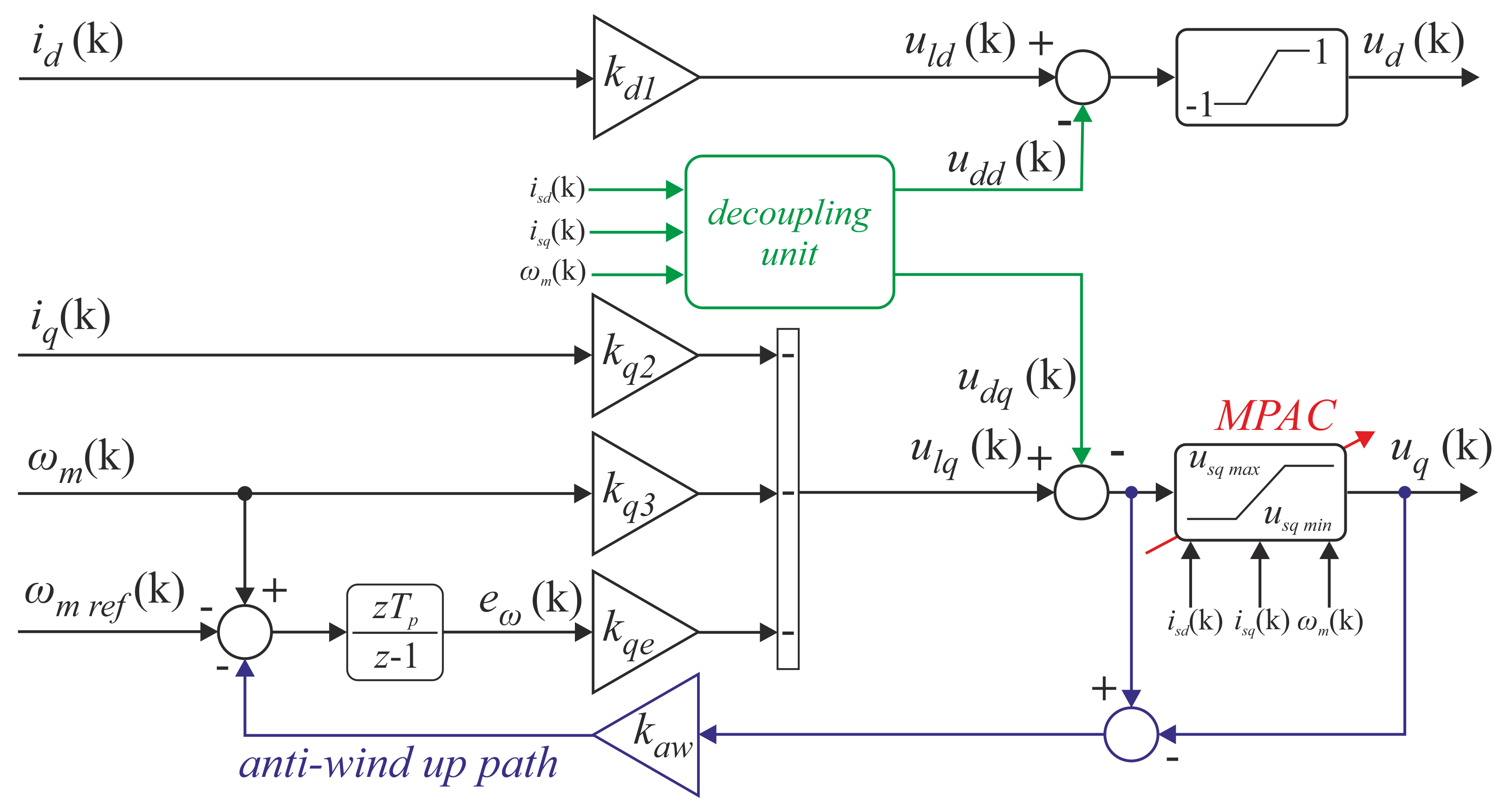
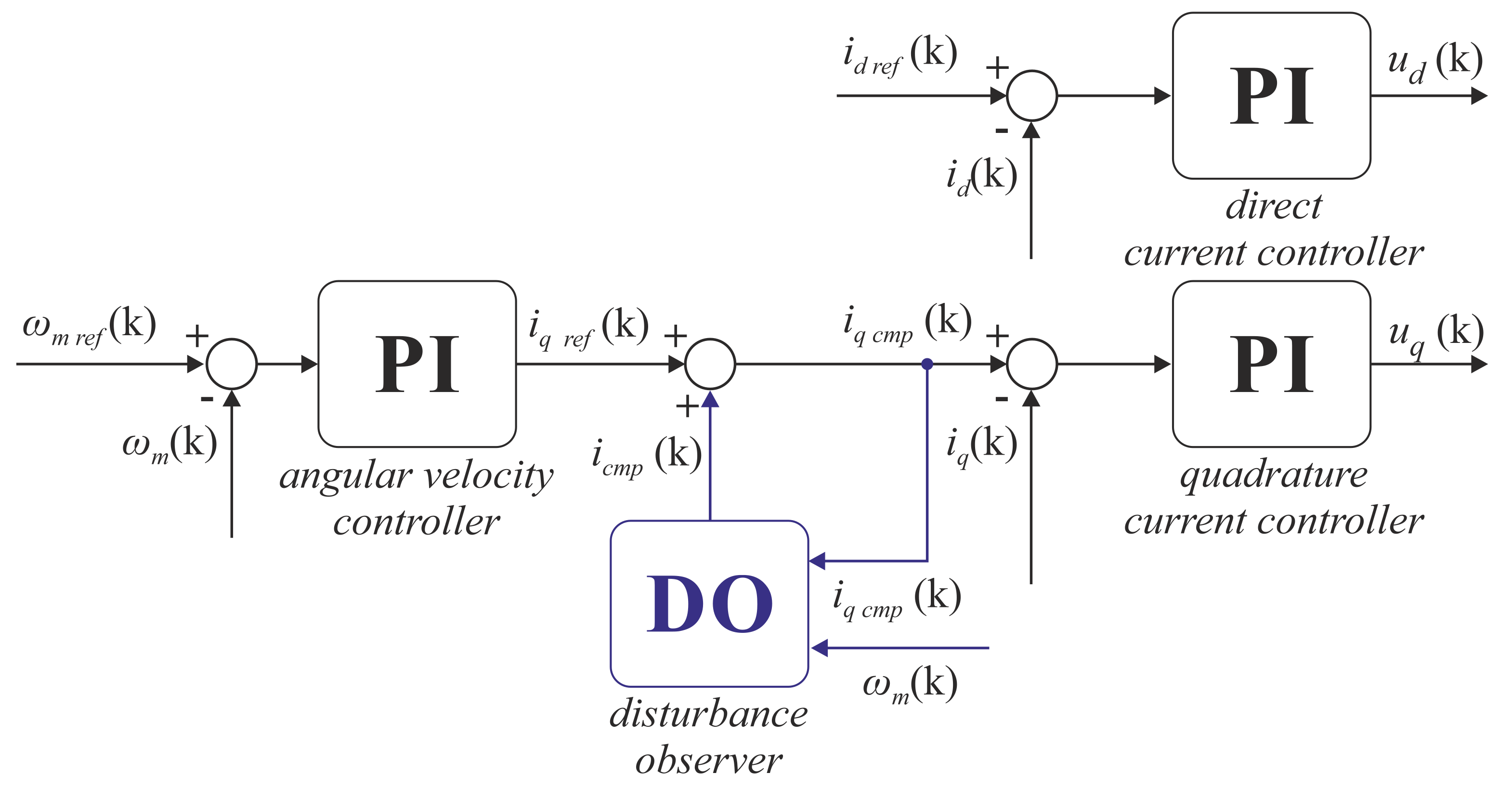
2.1. Employed Control Structure

In general, a cascade-free control structure does not contain any inner internal connections of controller blocks and, therefore, a single structure controls the evolution of all state-variables. In this paper, a SFC (Figure 1) is employed in order to regulate angular velocity. Safe operation of the motor requires to maintain the phase currents in a nominal range. A model predictive approach constraints (MPAC) algorithm and anti-windup path were introduced for current limitation. MPAC is a relatively novel and not complex method [1,16], which allows to limit the value of motor currents to a defined range. The a posteriori introduction of constraints does not affect the design procedure directly. Since control signals in real drive systems are limited, the integral action of a controller may cause the wind-up phenomenon. In such a case, the anti-wind up path ensures linear operation of the modulator by limiting the values of control signal to an available range. The decoupling unit realizes the linearization feedback of the plant, which enables simplification of the controller synthesis procedure. As a result, it may be realized as for a linear plant [7,16]. With respect to the aforementioned features, a discrete linear-quadratic optimization method may be employed for synthesis of the controller.
It is expected that the proposed control structure (SFC) will allow to achieve superior dynamic and static properties of the drive, with current limitation and smooth angular velocity operation. It is essential to set the gain coefficients appropriately. Since the most common approach for calculation of state feedback controller gain coefficients is based on a random trial-and-error procedure employing linear-quadratic optimization, it is relatively difficult and extremely time-consuming [1,16,18]. To overcome these issues, the controller will be tuned using a nature-inspired optimization method.

2.2. Auto-Tuning Algorithm

The main drawback of SFC tuning is caused by the lack of simple criteria for determining the controller coefficients. Therefore, a manual trial-and-error procedure is the most common approach employed in practice [1,16]. Hence, this task becomes highly non-trivial and random. In order to overcome these issues, a nature-inspired optimization method, i.e., an artificial bee colony algorithm, is proposed for determination of controller gains. This should lead to high performance, superior dynamic- and static properties of the drive. In [18], the off-line auto-tuning procedure is proposed. The objective function focuses on minimizing speed-tracking error for step changes of reference signal and load torque.
In this paper, a new objective function is proposed in order to minimize the torque ripple in steady-state. It allows to: (i) obtain a smooth steady-state velocity, (ii) minimize speed-tracking error, and (iii) maintain a zero d-axis current. The minimization of speed-tracking error defined in the performance index would result in high values of controller coefficients in order to achieve a high dynamic, which causes dangerous noises amplification. The most common methods used to prevent such behaviour are based on additional part in performance index aimed at minimizing the derivative of the control signal [17,18]. This approach requires expert knowledge and trial-and-error procedure to determine the proper gain coefficient for derivative limitation, which ensures satisfactory system response and safe system operation. Therefore, the proposed on-line auto-tuning procedure is supported by a violation function. It is responsible for minimization of dynamic properties of the system response and allows to ensure safe operation and current limitation. The tuning procedure is realized using a predefined reference signal. To introduce the violation function in the optimization process for developed performance index, the Deb’s rules are used [19]. The selection of the constraint-handling method is based on its simple implementation and parameter-free operation. This method modifies the selection process of two compared solutions: (i) a feasible solution is always better than infeasible one, (ii) for two feasible solutions, the one with lower performance index is selected, and (iii) for two infeasible solutions, the one with lower violation function is selected, where the feasible solution does not violate the assumed constraints, while the infeasible solution violates the constraints.
The main task of the auto-tuning procedure was to obtain a smooth velocity response with desired dynamics, the rise time of the small signal response should not be faster than 100 ms. Moreover, the phase currents should not exceed the value of 5 A. The main objectives of the defined tuning criterion were: (1) minimization of the velocity ripples caused by the periodic disturbances, and (2) maintaining the assumed dynamics with zero steady-state error. With respect to the aforementioned, a following novel performance index has been developed:
I ξ = k Δ ω Δ ω m ( ξ ) + k = 0 N 1 T s δ ω 2 ( ξ , k ) + δ i d 2 ( ξ , k )
with: δ ω ( ξ , k ) = ω r e f ( ξ , k ) ω m ( ξ , k ) , δ i d ( ξ , k ) = i d r e f ( ξ , k ) i d ( ξ , k ) , where: ξ —iteration number, k Δ ω —ripple gain coefficient, Δ ω m ( ξ ) —angular velocity ripples in steady-state Δ ω m ( ξ ) = ω m a x ω m i n measured for t 1 ; 2  s, N—number of samples for a single tuning iteration, δ ω ( ξ , k ) , δ i d ( ξ , k ) —angular velocity and d-axis current error in iteration ξ for sample k, respectively. It shall to be pointed out that the proposed cost function is relatively simple and intuitive, as it consists of velocity ripple in the steady state, the integral of the error signal of angular velocity, and the direct current component.
In order to solve the constrained high-dimensional optimization problem, which is on-line auto-tuning procedure, the Artificial Bee Colony algorithm was utilized. It requires a definition of a number of control parameters, listed in Table 1. These parameter selections are based on parameters used to solve similar optimization problems [17,18]. It should be noted that the optimization algorithm requires a definition of nine parameters, where three of them are related to the dimension of optimized parameters (D) and the size of colony (NP), where the dimension is a bounded value related directly to the optimized problem. Moreover, the value of modification rate (MR) is a default, which means it is not necessary to be defined by the user. This means that the proper operation of the optimization algorithm requires four of the parameters to be selected by the user: colony size (NP), maximum number of iterations (MNI), and lower and upper boundaries (lb and ub). The conducted experimental tests indicate that the tuning procedure may be successfully realized with a colony size of 10 bees until 90 iterations. Its aim is focused on determination of optimal weighting matrices for a given performance index. The step response of the drive system is analyzed in each iteration. It should be noted that the selection procedure based on Deb’s rule has been introduced into the ABC algorithm. It allows to drop all solutions that are violating the defined constraints (i.e., rise time and maximum current). The generalized pseudocode of the tuning procedure is presented in Algorithm 1. Detailed information about the ABC optimization algorithm may be found in [17,18].
Algorithm 1 Artificial Bee Colony algorithm.
1:
INITIALIZATION PHASE:
2:
   Random selection of food sources
3:
for predefined number of iteration ( M N I )do
4:
   EMPLOYED BEES PHASE ( F N ):
5:
     Global optimization strategy:
6:
          Searching in the global area defined by boundaries
7:
     Evaluation—step response for generated gains
8:
     Performance index calculation (1)
9:
   ONLOOKER BEES PHASE:
10:
     Local optimization strategy:
11:
          Searching in the neighborhood of the best solution for a better one
12:
     Evaluation—step response for generated gains
13:
     Performance index calculation (1)
14:
   SCOUT PHASE:
15:
     Prevention of premature stagnation strategy
16:
     Evaluation—step response for generated gains
17:
     Performance index calculation (1)
18:
end for

3. Experimental Results

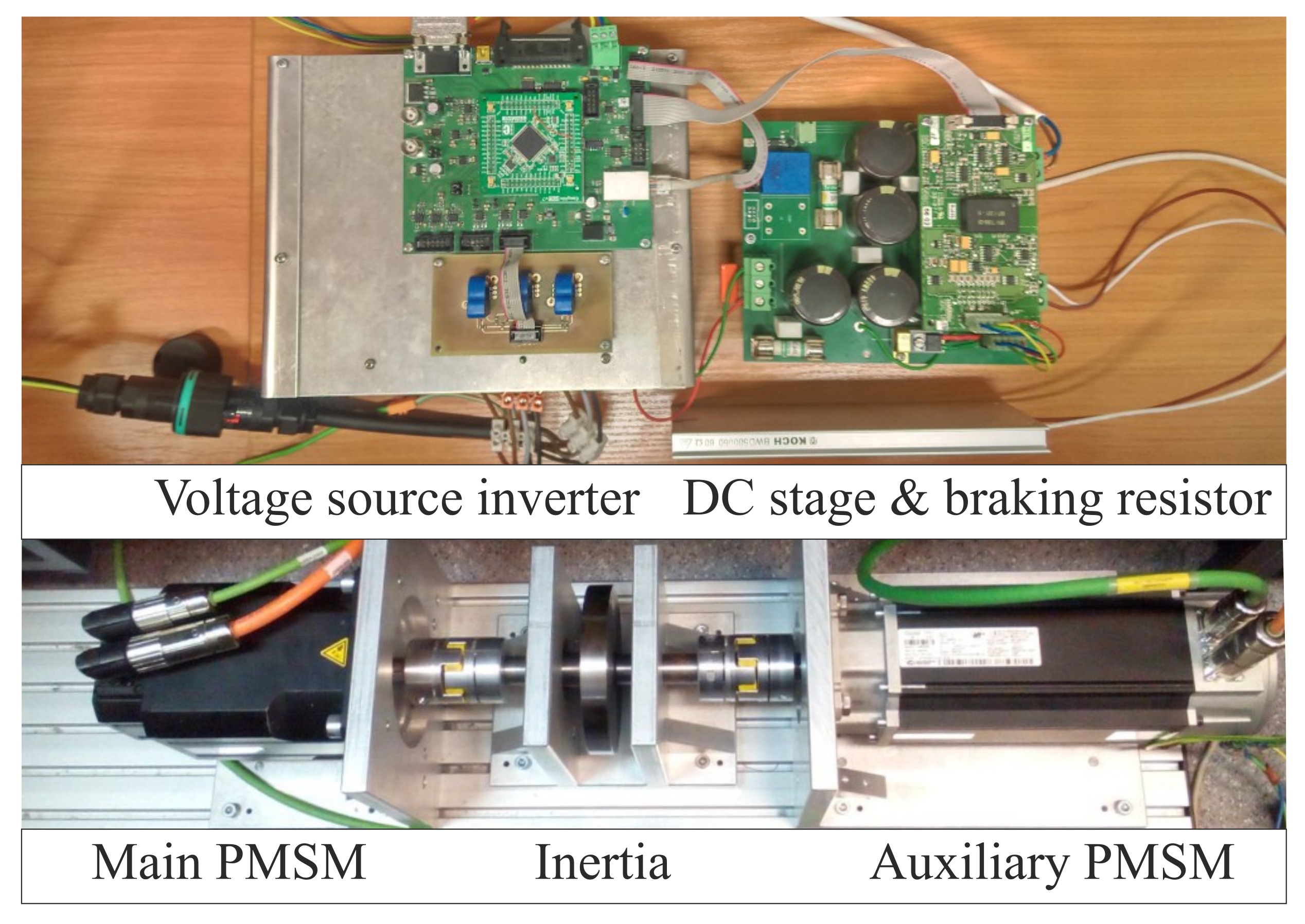
3.1. Laboratory Stand

The designed control structure (SFC-MPAC) was experimentally investigated on a PMSM drive system. The laboratory stand consists of two PM AC drives, the main motor (LTi Drives LST-127-2-30-560) and the auxiliary load motor (Emerson 115U2D300VAC). The first one is fed from a prototype 2-level voltage source inverter equipped in SiC power semiconductor devices. The developed control system has been implemented in a STM32F407VGT6 microcontroller (ARM M-4 Cortex, 168 MHz clock). The execution time (ET) for SFC-MPAC is about 9.8 μ s, while for the CCS it is about 9.4 μ s. The ABC tuning procedure was implemented on a PC station with Intel i5 3.0 GHz processor and 8 GB RAM using Mathworks Matlab software. The data between the drive and PC station was exchanged in real-time. The measurement paths are realized using LEM LTS15-NP current transducers and Sick Stegmann SRS 50 single-turn absolute encoder. The load drive is supplied by a commercial inverter (Unidrive SP1405 from Control Techniques) in torque regulation mode. The photo of the laboratory stand is presented on Figure 2. Electrical and mechanical parameters of the investigated drive system are summarized in Table 2.

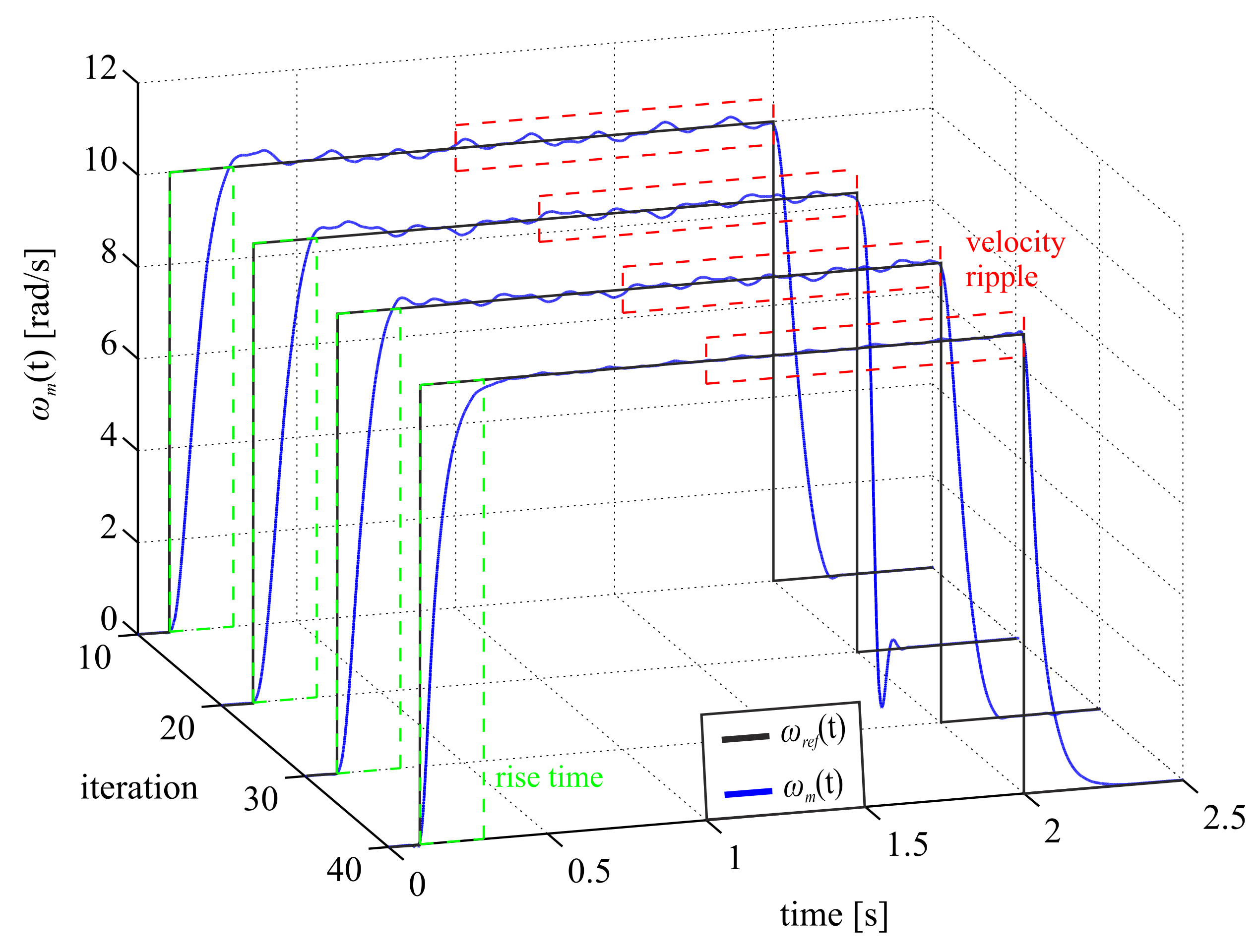
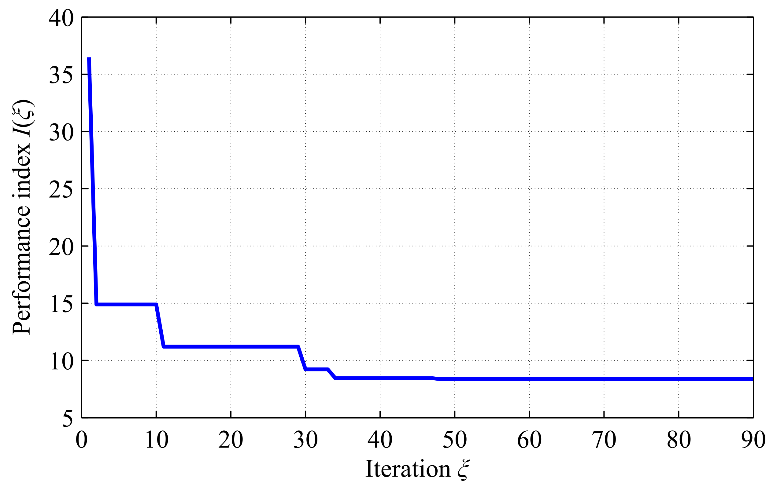
3.2. Tuning Experiment

In Figure 3, the obtained velocity responses were presented for selected iterations of the tuning procedure. The green rectangle represents the time window related to rise time calculation, whereas the red one is related to velocity ripple calculation. It can be seen that for iterations under 40, a relatively high velocity ripple occurs. The amplitude of the ripple is reduced in the following iterations, and reaches its lowest value for iteration 40 for the first time. The evolution of the performance index I ( ξ ) is presented on Figure 4, with its value at the end of the tuning procedure (after 90 iteration) being equal to about 8.38. The behavior of the velocity response indicates that the developed cost function may be introduced in a drive system in order to achieve the desired dynamics and obtain smooth velocity operation by significant reduction of the ripple. The introduction of proposed auto-tuning for a SFC allows to achieve superior compensation properties of periodic disturbances. The employed optimization algorithm is capable of finding a set of controller coefficients, which satisfies the defined cost function. Obtaining such good operation properties using a trial-and-error procedure may be very difficult and extremely time-consuming.
Since some obtained values of controller gain coefficients were relatively small ( 10 14 ÷ 10 16 ), they were assumed as equal to zero in (2). The optimal gain matrix K d has the following form:
K d = 1.13 e 1 0.0 0.0 0.0 0.0 8.99 e 2 3.23 e 1 5.23 e + 0
The controller gain coefficients have been determined by the employed ABC optimization method, which minimizes the developed cost function (1). It is worth noting that obtained coefficients are in good agreement with the solution presented in [16], where SFC has been used to control the PMSM drive.
The operation properties of the proposed control system were compared to a classical cascade control structure with PI controllers, the values of the controller coefficients for CCS and DOBC (Figure 5) are summarized in Table 3. The DOBC structure is based on PI-CCS with an additional compensation path based on disturbance observer (DO) [15]. In practice, it is not a trivial task, and it requires expert-knowledge. The main aim of the introduced DO is to estimate the disturbance and to cancel it subsequently. Since the DOBC system is based on an inverse transfer function of the mechanical part of the drive, in order to implement it, a filter should be introduced to make the transfer function proper or at least realizable [15]. In such a case, a successful design of DOBC crucially depends on the design of the filter. The current control loop was tuned using IMC tuning criterion [20], whereas the angular velocity control loop was tuned using the symmetrical optimum criterion. To reduce the velocity overshoot a first-order low-pass filter was introduced on the reference signal.

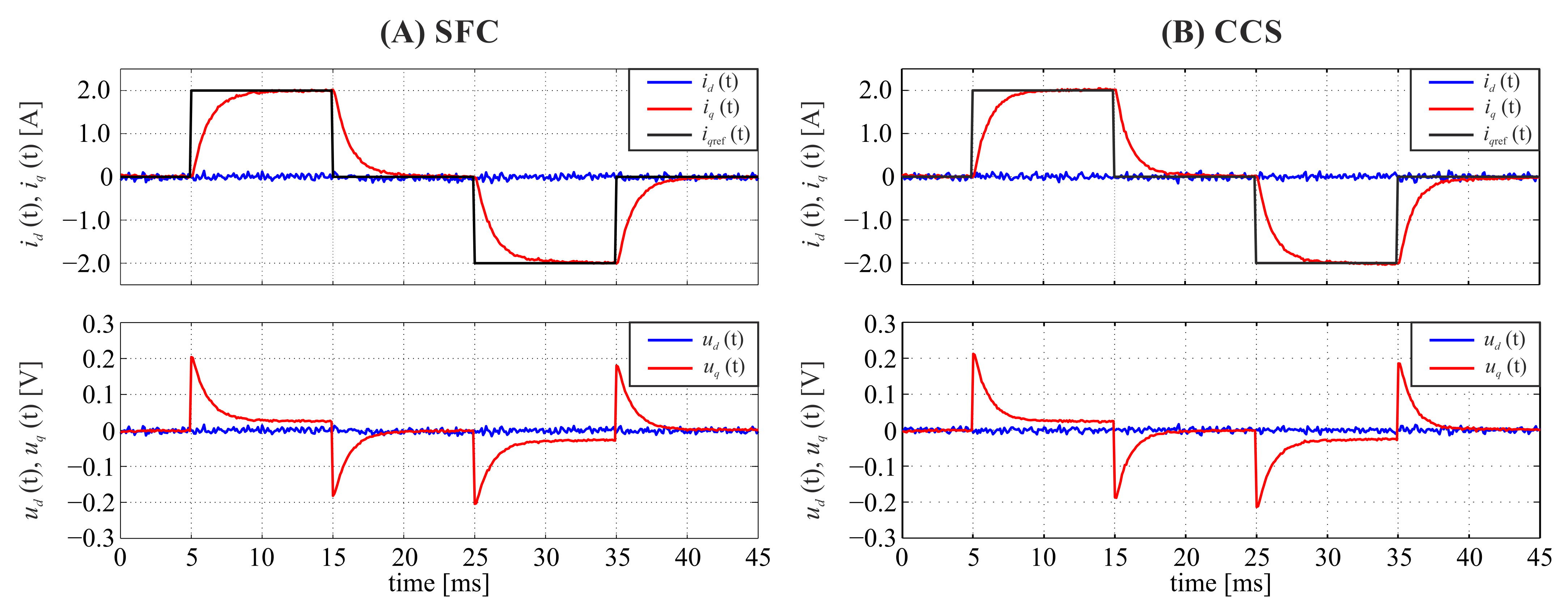
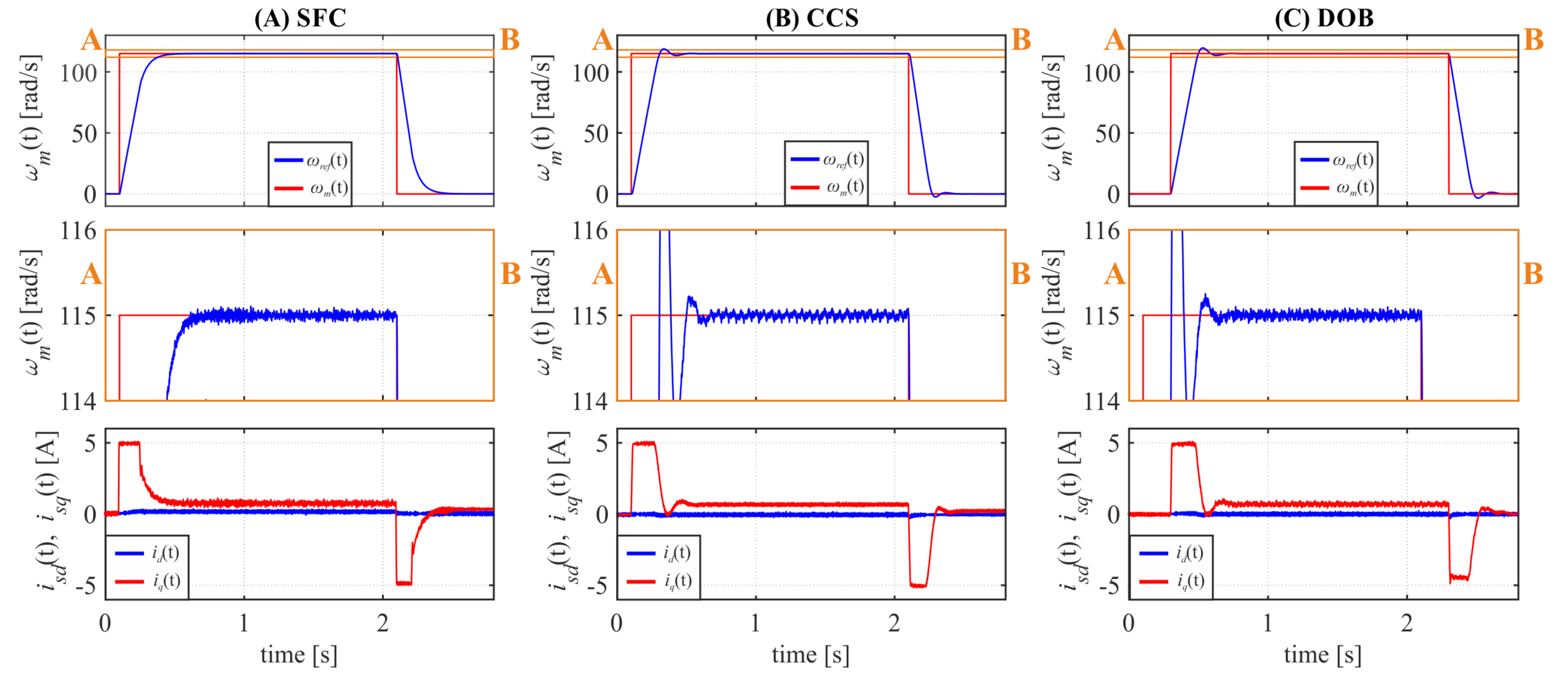
3.3. Quadrature-Current Step Response

The disturbance compensation of the investigated drive system is related to the dynamics of the q-axis current component. Therefore, a fair comparison of the dynamical properties of the investigated control systems can be obtained for similar behavior of the current only. Since the proposed SFC has no inner current control loop, it was necessary to introduce a virtual load signal [21] into the control structure to investigate the dynamics of the current. The SFC is realized without inner current control loop and, therefore, no reference signal of quadrature current component is present. In such a case, it is impossible to set the desired value of i q directly. In order to obtain an equivalent current response, a step change of virtual load signal has been introduced. The control system forces the current in order to compensate the introduced virtual load what corresponds to a step response of current in a CCS. It should be mentioned that the motor shaft was immobilized during current loop testing. The experimental results of motor current response are present in Figure 6.
The obtained rise time for the SFC based structure is about 2.55 ms, whereas for the CCS it is approximately 2.3 ms. The presented data indicates that the dynamics of current response for CCS and SFC based structures is similar with a 10% advantage by the CCS side. Since the dynamics of motor currents is similar for both control structures, it cannot affect the attenuation properties of disturbances present in the investigated system.

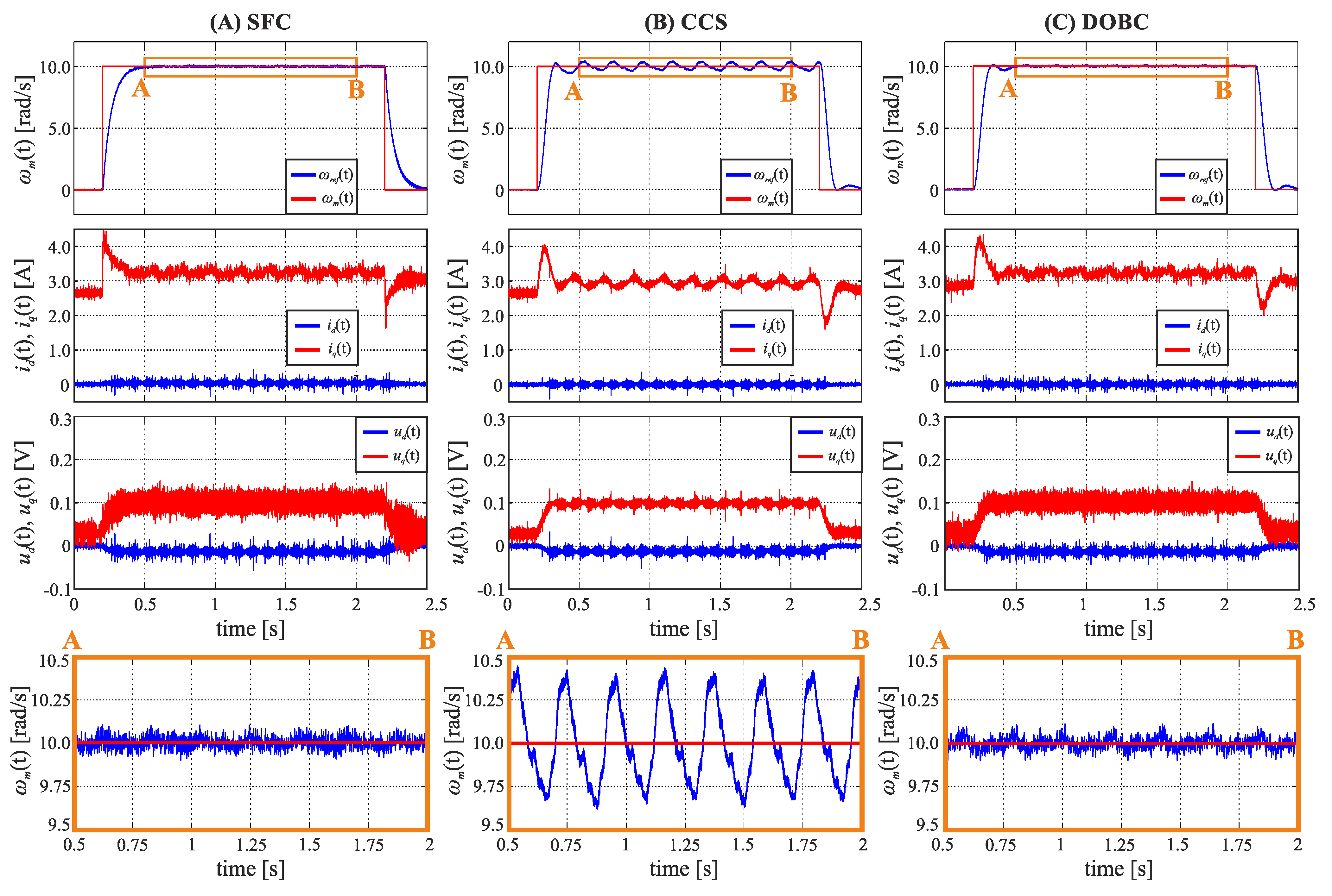
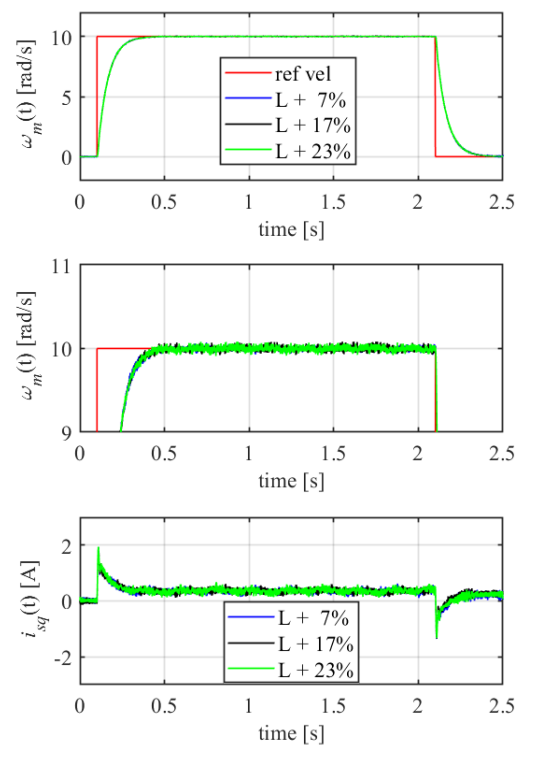
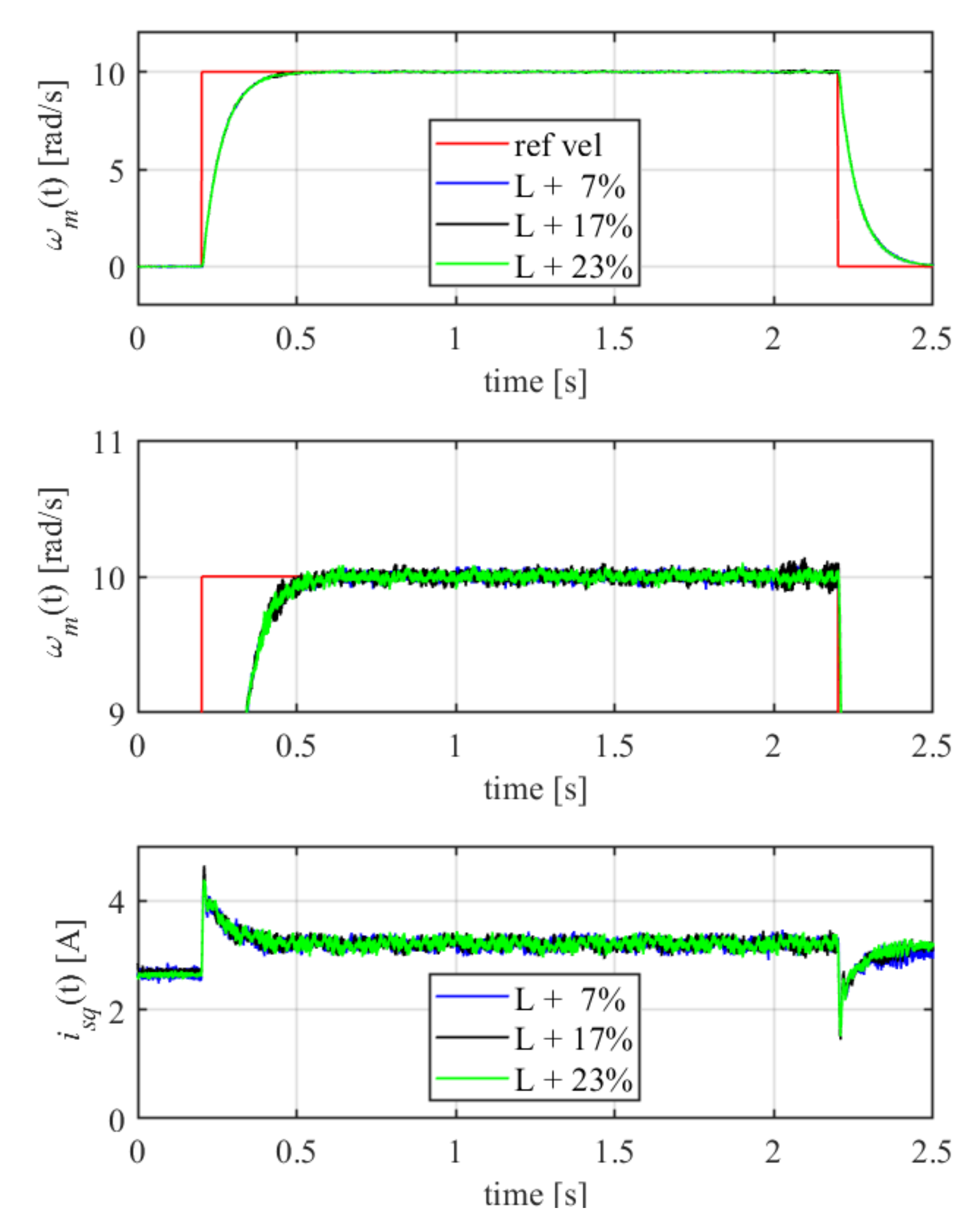
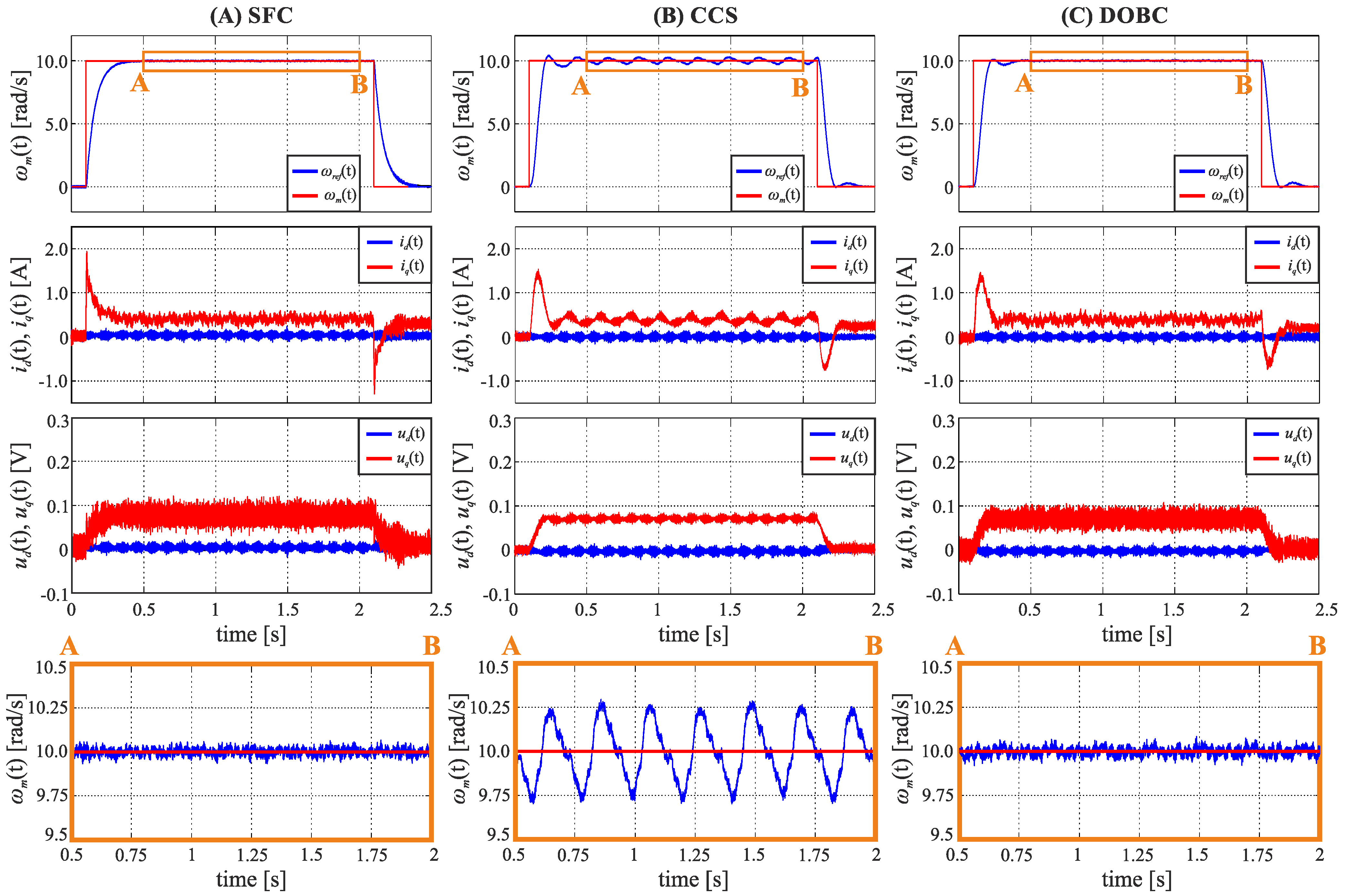
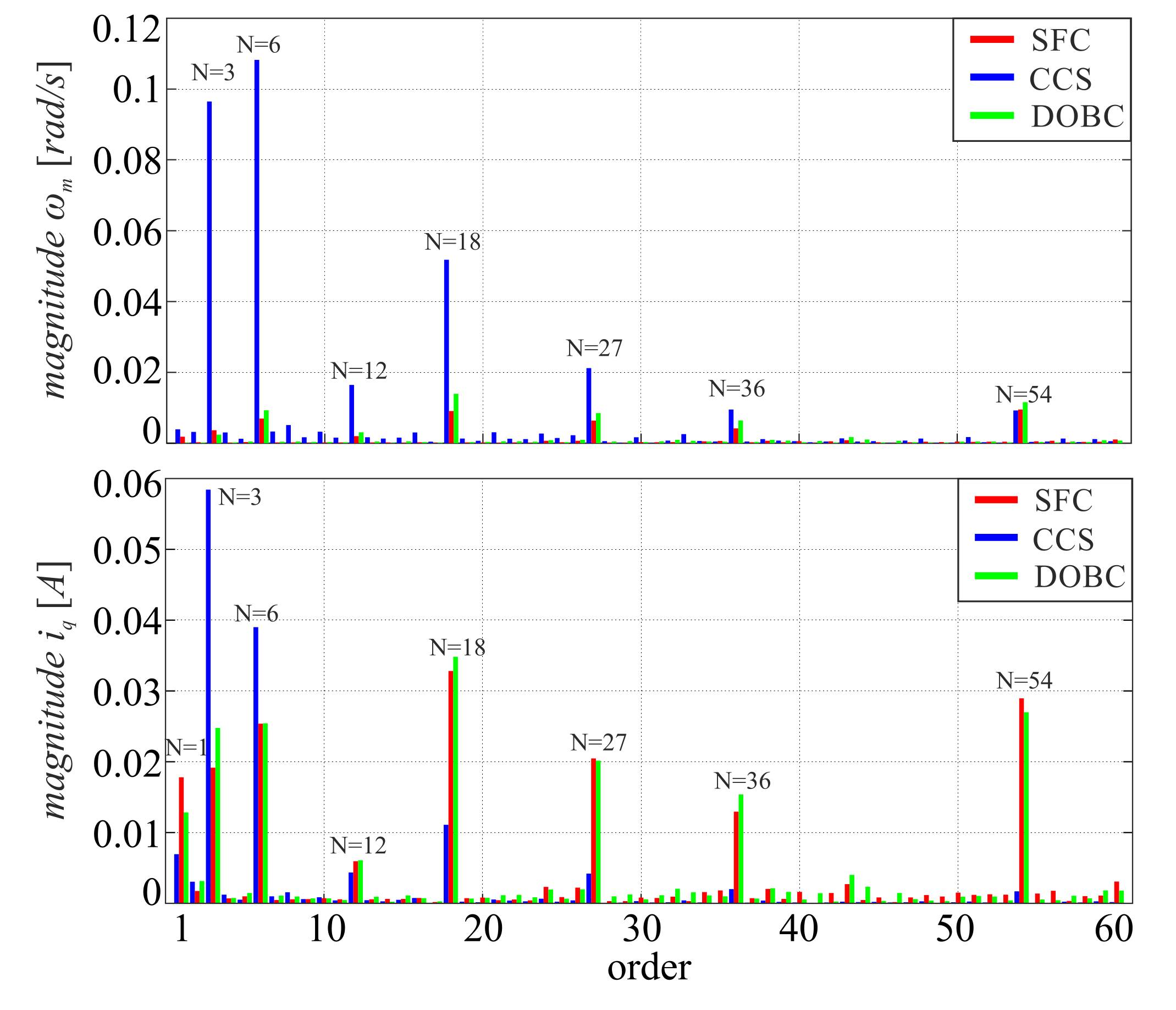
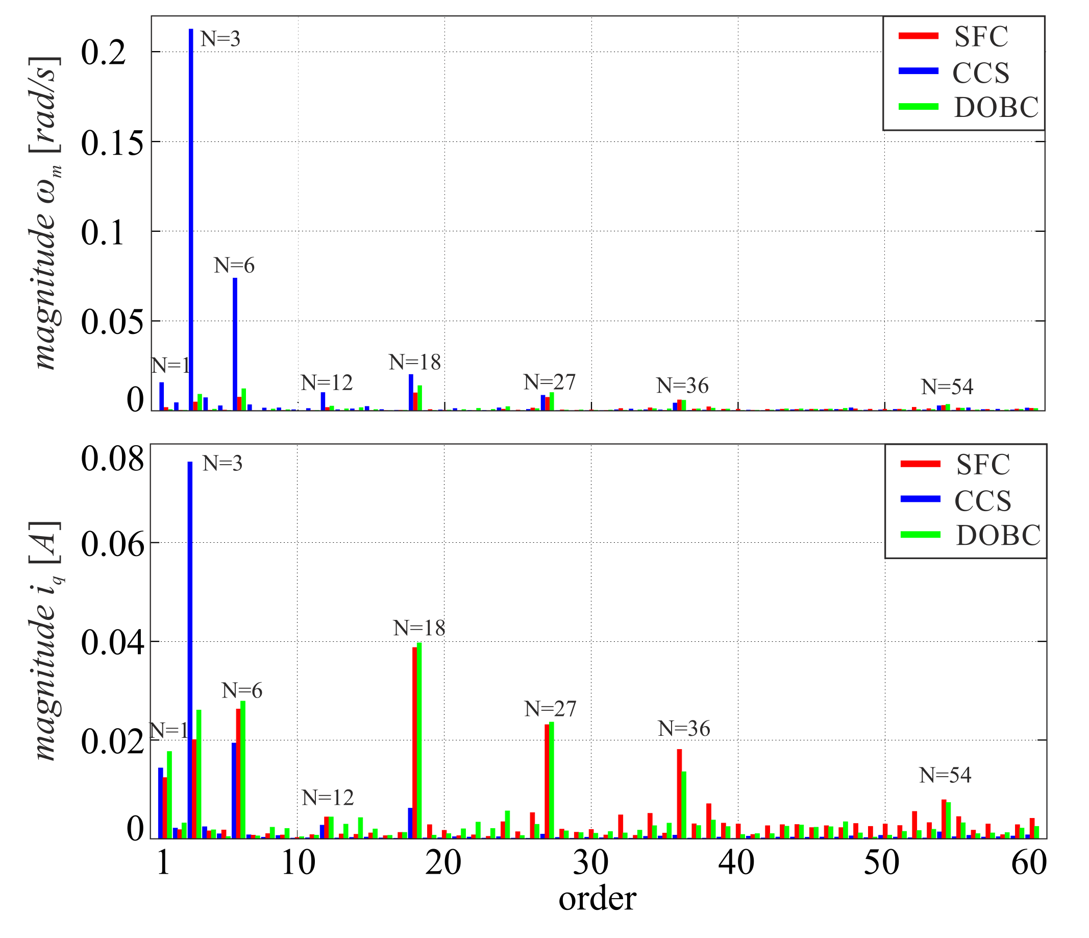
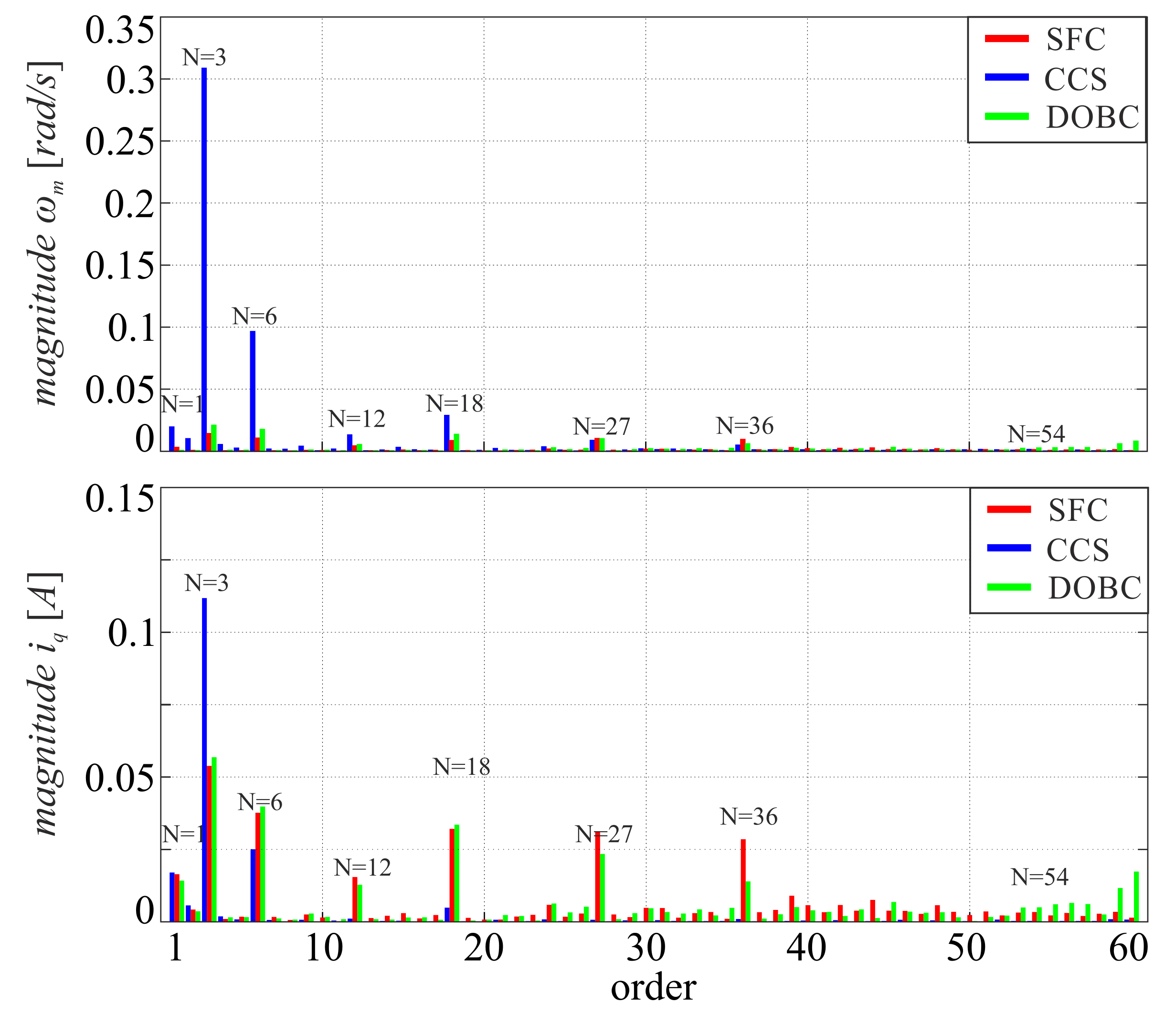
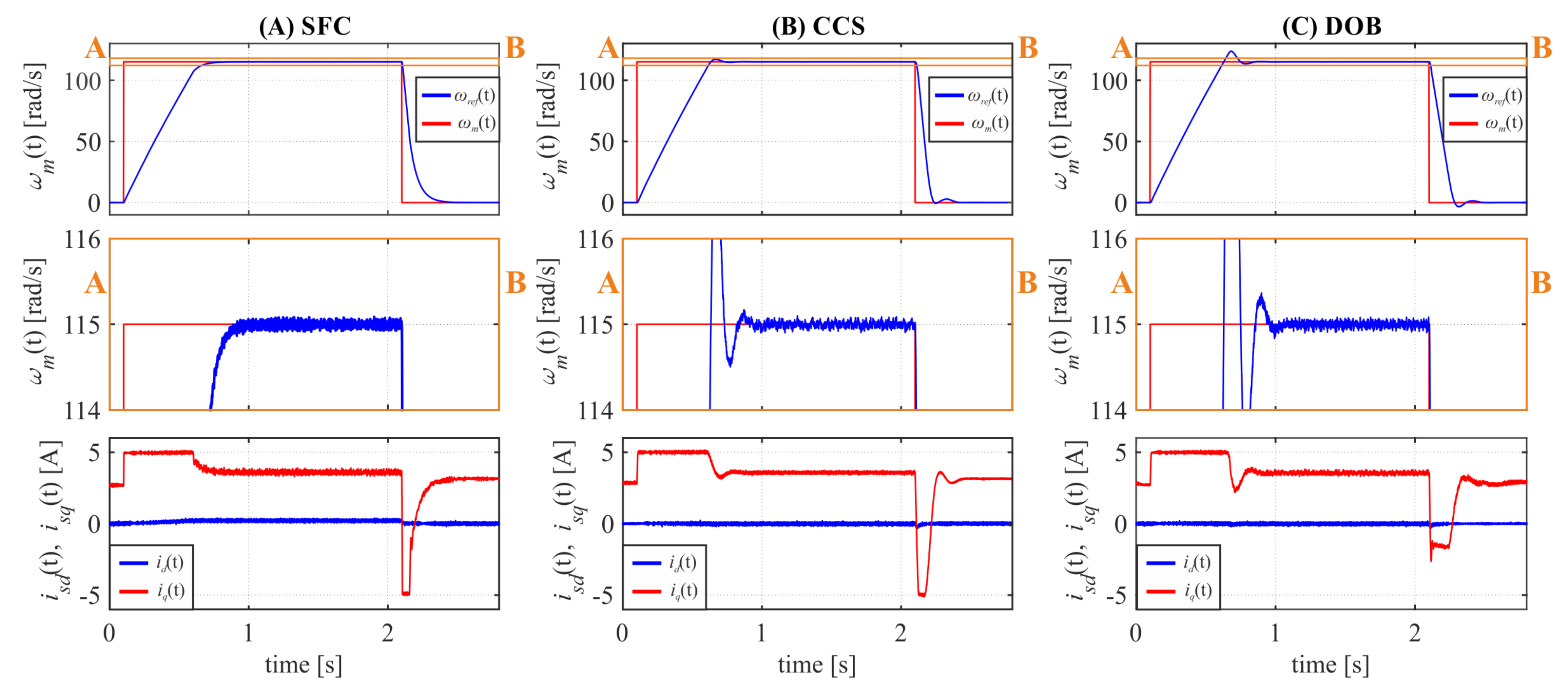
3.4. Velocity Step Response

Since the periodic disturbances mainly deteriorate the operation quality of the drive at low speed range, detailed investigations in time-domain was carried out for a set reference of 10 rad/s under no load and constant load operation. The frequency-domain analysis was additionally extended for angular velocity equal to 5 rad/s.
The step response for obtained controller coefficients is presented on Figure 7A, the rise time t r is about 130.2 ms and the amplitude of velocity ripples Δ ω m is equal about 0.173 rad/s. It can be seen that the dynamical properties of the control system tuned by the proposed algorithm met the requirements (i.e., rise time and current limit), resulting in smooth rotational velocity in steady-state and achieving the desired dynamics, and neither the current nor the rise time exceeds the given limits. The obtained step response of CCS is shown in Figure 7B, whereas Figure 7C contains the DOBC response. Comparing the obtained results for SFC and CCS structures, the following features can be observed:
1.
The regulation time of compared control structures is equal to 178.5 ms for SFC and 103.3 ms for CCS;
2.
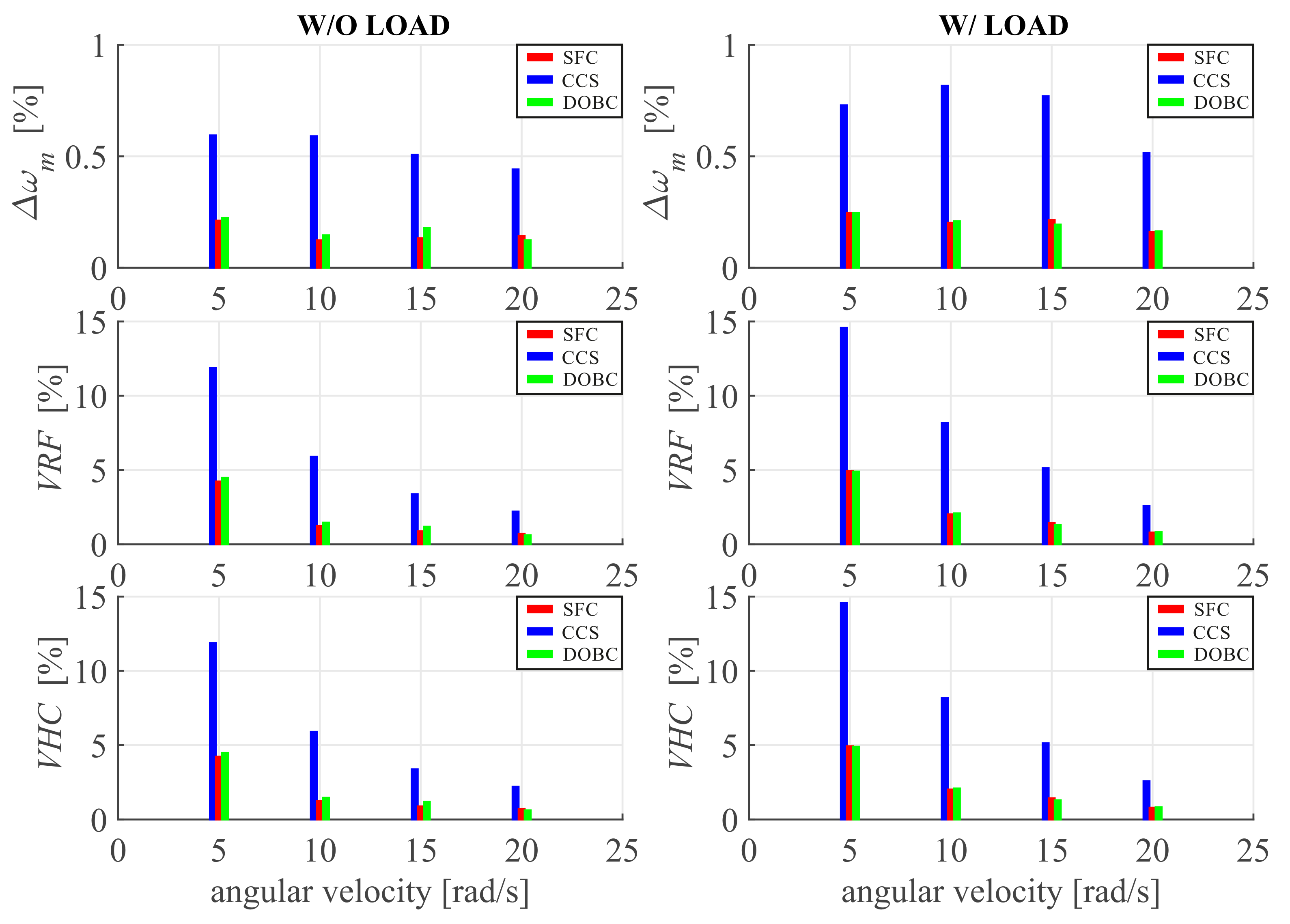
The level of velocity ripple for a classical CCS with PI controllers is much higher than for a system based on SFC (0.591 rad/s vs. 0.173 rad/s);
3.
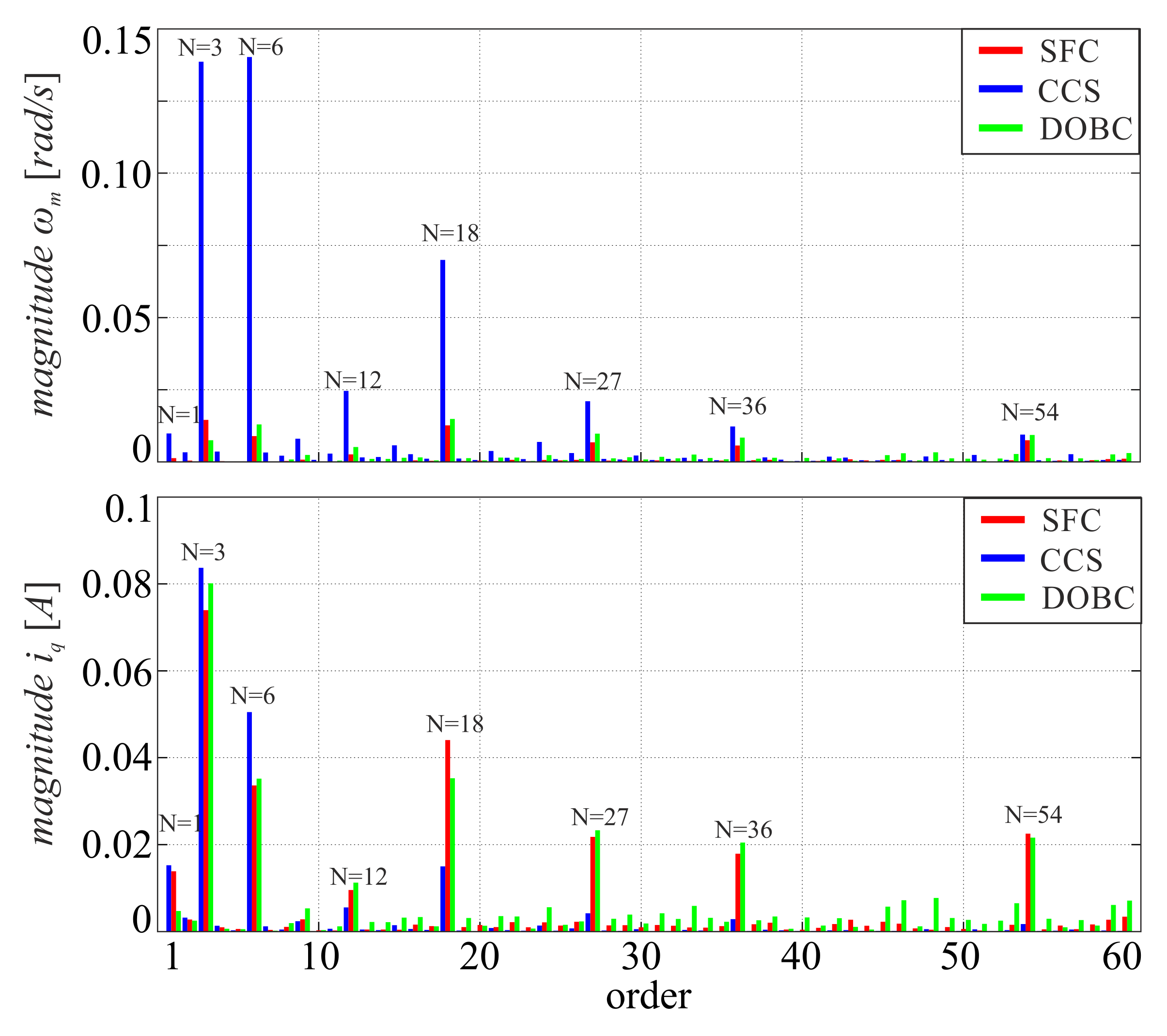
In respect to (2) the attenuation of periodic disturbances present in the investigated PMSM drive is much higher in the SFC based control system;
4.
An ABC based tuning procedure can be successfully employed for the proposed SFC structure in order to obtain smooth operation of the drive.
Since the current dynamics of investigated control structures is similar, the worse attenuation of disturbances for CCS is not directly related to the dynamics of current control loop. This indicates that the compensation capability for cascade connection of velocity and current controller is not as good as for a single state feedback controller. Comparable disturbance rejection properties may be achieved after introduction of a disturbance-observer (Figure 7C). A detailed frequency-domain analysis was carried out for obtained velocity and current response signals.
The frequency-domain data presented on Figure 8 and Figure 9 indicates that the proposed SFC enables to obtain extremely high attenuation of periodic disturbances in a drive system with PMSM. It can be seen that the presented spectra contain several harmonic components. All of them correspond to the expected ones.
Considering that the investigated motor has three pole-pairs, the electrical angular position is equal to three times of the mechanical angle. Therefore, the expected harmonic orders of periodic disturbances related to mechanical angular velocity in this particular drive system are as follows: current offset- and scaling-error—3rd and 6th [8], dead-time phenomenon—18th [2,8], flux-harmonics—18th [2], AHC—6th and 27th [22], and NHC—54th [23]. Some of aforementioned components overlap and, therefore, it is impossible to determine the contribution of some particular phenomenon on the overall magnitude of the given harmonic.
The obtained results (Figure 8 and Figure 9) indicate that all of the harmonic components of angular velocity are reduced for the SFC and DOBC, where the first one achieves a slightly better compensation. It can be seen that the employed control structures introduce several additional harmonic components in the q axis current i q for compensation of pulsating torque. Since the periodic disturbances deteriorate the angular velocity mostly in the low speed region, the reduction factor is the most significant for lower velocities. It should be noted that the magnitudes of current components related to measurement errors are lower for the proposed control structure, which indicates better robustness to measurement errors of currents.
The drives system behaviour was also investigated for operation under a constant load set to 3 Nm. The constant load torque was introduced using the auxiliary PMSM drive (Figure 2). The obtained results are presented in: Figure 10A—SFC, Figure 10B—CCS, and Figure 10C—DOBC. It can be seen that the velocity response of the SFC based system meets the dynamical requirements set (i.e., rise time, zero steady-state error) and the velocity ripple is relatively low. Comparing the obtained step-responses of SFC and CCS structures under constant load operation, the following features can be observed:
1.
The regulation time of compared control structures is equal to 183.4 ms for SFC and 104.1 ms for CCS at constant load operation;
2.
The level of velocity ripple for classical CCS with PI controllers is also much higher than for a SFC based system (0.817 rad/s vs. 0.202 rad/s);
3.
The proposed control structure (SFC) ensures smooth operation of the drive with constant load torque;
4.
With respect to (2) the attenuation of periodic disturbances is much better in the SFC based control system.
Similar, as in the previous case, a frequency-domain analysis was carried out for a set reference of 5 rad/s and 10 rad/s. The obtained results are presented on Figure 11 and Figure 12. The calculated frequency spectra indicate that the SFC based drive system significantly reduces the impact of periodic disturbances on the angular velocity of the drive, also in case of operation under constant load. Almost all of the components are strongly attenuated, resulting in relatively smooth rotational speed of the drive. The quadrature current component contains additional harmonics, which are responsible for compensation of the periodic disturbances present in the investigated control system.
It should be mentioned that the aim of proposed auto-tuning procedure is related to attenuation of periodic disturbances and, therefore, the regulation time is a trade off between the attenuation ability and the set rise time limit. The obtained gain coefficients met the boundaries set and allow to reach the best possible limitation of the velocity ripple. This is the reason for the worse response dynamics of the SFC based structure. The modification of the rise time limit would allow to reach better dynamical properties.
Figure 13 summarizes several quality indicators for selected angular velocities. The quality indicators were calculated for rotational speeds equal to: 5, 10, 15, and 20 rad/s. The selected indicators are related to the value of angular velocity ripple and overall harmonic content of the obtained responses at steady-state. The velocity ripple factor ( V R F ) is given by a following formula:
V R F = Δ ω m ω r e f × 100 %
The velocity harmonic content ( V H C ) defines the amount of harmonic components present in the angular velocity in steady state. This indicator should possibly be low to obtain a ripple-less and smooth response of the drive system. It is defined as follows:
V H C = n = 1 N = 60 ω n 2 ω D C × 100 %
where: ω n , ω D C —magnitude of the n-th and D C harmonic component of angular velocity, respectively.
The calculated quality-indicators (Figure 13) show that the level of velocity ripple is 2.8 ÷ 4.8 and 2.9 ÷ 4.0 times lower for SFC in comparison to classical CCS at drive operation without and with load, respectively, whereas it is at a similar level in comparison to DOBC. It proves the superior ability for compensation of periodic disturbances of the proposed state feedback based control system. It should be noted that the operation quality of the drive suffers mostly in the low speed area, where the magnitude of the DC component of angular velocity is relatively low. In all cases the amplitude of velocity ripple is higher for drive operation under load, which is caused by a higher impact of current measurement errors present in the system. The ripple level increases under load operation of the drive in the range of 12 ÷ 65 % for CCS, 4 ÷ 40 % for SFC and 9 ÷ 43 % for DOBC. A quite different situation occurs for the V H C indicator, as its value is 6.4 ÷ 11.9 and 6.4 ÷ 10.7 times higher for CCS in comparison to SFC under no load and load operation, respectively. A relatively low content of harmonic for SFC and DOBC based drive systems indicates that the velocity ripple are caused mainly by harmonics of order above 60. In such a case, it can be stated that the operation quality of the drive system suffers mostly under digital accuracy and quantization errors of angular velocity measurement. Whereas, in the case of CCS, the velocity ripples are directly related to the periodic disturbances present in the drive. It should be mentioned that the impact of pulsating torque decreases for higher rotational speeds, which is in line with the scientific literature. The obtained results for SFC and DOBC summarized in Figure 13 indicate that the investigated control structure allows to reach comparable operation quality with an advantage on the SFC side. The exact values of obtained quality indicators are summarized in Table 4. It should be pointed out that superior operation properties are achieved without any additional disturbance observers.
The SFC robustness has been investigated for the inductance and resistance variation of the phase windings. The experimental tests were conducted for the drive system with additional coils connected in series to the motor terminals. The inductance values of introduced coils are about 0.65, 1.5, and 2.1 mH, giving up to 7%, 17%, and 23% of nominal phase inductance. The increase of resistance was equal to: 0.04, 0.1, and 0.14 Ω , corresponding to 4%, 10%, and 14% of primary resistance. The obtained results are present in Figure 14 and Figure 15. It indicates that the investigated control structure is robust against variations of inductance and resistance. It can be observed that the output velocity is smooth, and that the pulsating torque is highly attenuated. The results are in line with the theoretical expectations.
Additional experimental tests were prepared to confirm of proper operation of the investigated control structures in the high-speed region for a given reference of 115 rad/s without (Figure 16) and with (Figure 17) external load. The obtained results indicate the proper operation of investigated control structures in the high-speed area. The error in the steady state is equal to zero, the current is properly limited to the assumed value, and the load torque does not deteriorate the properties of the control system. The velocity is ripple-free in all cases, which is in line with the theoretical expectations.

4. Conclusions

In this paper, attenuation ability of periodic disturbances for a PMSM drive was investigated. The SFC gain coefficients were determined using a nature inspired on-line auto-tuning algorithm in order to achieve superior attenuation ability of periodic disturbances. The developed performance index ensures proper tuning of constrained SFC with respect to velocity ripple minimization.
Dynamic and static properties of the discussed control system were compared with a classical CCS and DOBC based on PI controllers using time- and frequency-domain analysis. The conducted experimental tests indicate that superior attenuation ability of periodic disturbances in a PMSM drive system may be obtained by employing a constrained SFC structure. It should be pointed out that good operation properties are achieved without using any observers or estimators, with only a classical SFC structure with simple MPAC being employed, supported by nature-inspired optimization algorithm with special-designed performance index. This confirms the robustness and excellent disturbance rejection capability of the investigated SFC structure. Moreover, the angular velocity is properly controlled without steady-state error for a wide range of operation at no-load and load torque operation.
The robustness investigations of SFC indicate that the system is immune against inductance and resistance variations in the range of about 20% of its nominal values.
It should be pointed out that the novelty and strength of the proposed structure is its practical approach to attenuation of periodic disturbances present in PMSM drive systems. It is a complex proposal for ripple reduction using a SFC structure with novel engineering tools. Since a basic control structure is employed and the tuning procedure is flexible, it may be applied successfully to other drive systems.

Author Contributions

Conceptualization, Ł.J.N.; methodology, Ł.J.N., R.S., T.T. and L.M.G.; software, Ł.J.N. and R.S.; validation, Ł.J.N., R.S., T.T. and L.M.G.; formal analysis, Ł.J.N.; investigation, Ł.J.N. and R.S.; resources, Ł.J.N.; data curation, Ł.J.N.; writing—original draft preparation, Ł.J.N.; writing—review and editing, Ł.J.N., R.S., T.T. and L.M.G.; visualization, Ł.J.N.; supervision, T.T. and L.M.G.; project administration, Ł.J.N.; funding acquisition, Ł.J.N. and T.T. All authors have read and agreed to the published version of the manuscript.

Funding

This research was supported by the basic research fund of the Department of Automatics and Measurement Systems, Nicolaus Copernicus University, Poland.

Institutional Review Board Statement

Not applicable.

Informed Consent Statement

Not applicable.

Data Availability Statement

Not applicable.

Conflicts of Interest

The authors declare no conflict of interest.

References

  1. Tarczewski, T.; Grzesiak, L.M. Constrained State Feedback Speed Control of PMSM Based on Model Predictive Approach. IEEE Trans. Ind. Electron. 2016, 63, 3867–3875. [Google Scholar] [CrossRef]
  2. Yang, J.; Chen, W.; Li, S.; Guo, L.; Yan, Y. Disturbance/Uncertainty Estimation and Attenuation Techniques in PMSM Drives-A Survey. IEEE Trans. Ind. Electron. 2017, 64, 3273–3285. [Google Scholar] [CrossRef] [Green Version]
  3. Zhao, K.; Yin, T.; Zhang, C.; Li, X.; Chen, Y.; Li, T.; He, J. Sliding mode-based velocity and torque controllers for permanent magnet synchronous motor drives system. J. Eng. 2019, 2019, 8604–8608. [Google Scholar] [CrossRef]
  4. Adase, L.A.; Alsofyani, I.M.; Lee, K. Predictive Torque Control With Simple Duty-Ratio Regulator of PMSM for Minimizing Torque and Flux Ripples. IEEE Access 2020, 8, 2373–2381. [Google Scholar] [CrossRef]
  5. Shi, T.; Yan, Y.; Zhou, Z.; Xiao, M.; Xia, C. Linear Quadratic Regulator Control for PMSM Drive Systems Using Nonlinear Disturbance Observer. IEEE Trans. Power Electron. 2020, 35, 5093–5101. [Google Scholar] [CrossRef]
  6. Sandre-Hernandez, O.; Rangel-Magdaleno, J.; Morales-Caporal, R. Modified model predictive torque control for a PMSM-drive with torque ripple minimisation. IET Power Electron. 2019, 12, 1033–1042. [Google Scholar] [CrossRef]
  7. Niewiara, Ł.J.; Tarczewski, T.; Grzesiak, L.M. Application of extended Kalman filter for estimation of periodic disturbance and velocity ripple reduction in PMSM drive. Bull. Pol. Acad. Sci. Tech. Sci. 2020, 68, 983–995. [CrossRef]
  8. Chung, D.-W.; Sul, S.-K. Analysis and compensation of current measurement error in vector-controlled AC motor drives. IEEE Trans. Ind. Appl. 1998, 34, 340–345. [Google Scholar] [CrossRef]
  9. Houari, A.; Bouabdallah, A.; Djerioui, A.; Machmoum, M.; Auger, F.; Darkawi, A.; Olivier, J.; Benkhoris, M.F. An Effective Compensation Technique for Speed Smoothness at Low-Speed Operation of PMSM Drives. IEEE Trans. Ind. Appl. 2018, 54, 647–655. [Google Scholar] [CrossRef]
  10. Tang, M.; Formentini, A.; Odhano, S.A.; Zanchetta, P. Torque Ripple Reduction of PMSMs Using a Novel Angle-Based Repetitive Observer. IEEE Trans. Ind. Electron. 2020, 67, 2689–2699. [Google Scholar] [CrossRef] [Green Version]
  11. Jo, I.; Lee, H.; Jeong, G.; Ji, W.; Park, C. A Study on the Reduction of Cogging Torque for the Skew of a Magnetic Geared Synchronous Motor. IEEE Trans. Magn. 2019, 55, 1–5. [Google Scholar] [CrossRef]
  12. Bozorgi, A.M.; Farasat, M.; Jafarishiadeh, S. Model predictive current control of surface-mounted permanent magnet synchronous motor with low torque and current ripple. IET Power Electron. 2017, 10, 1120–1128. [Google Scholar] [CrossRef]
  13. Feng, G.; Lai, C.; Kar, N.C. A Closed-Loop Fuzzy-Logic-Based Current Controller for PMSM Torque Ripple Minimization Using the Magnitude of Speed Harmonic as the Feedback Control Signal. IEEE Trans. Ind. Electron. 2017, 64, 2642–2653. [Google Scholar] [CrossRef]
  14. Pajchrowski, T. Application of neural networks for compensation of torque ripple in high performance PMSM motor. In Proceedings of the 2017 19th European Conference on Power Electronics and Applications (EPE’17 ECCE Europe), Warsaw, Poland, 11–14 September 2017; pp. P1–P8. [Google Scholar]
  15. Shahruz, S.M. Performance enhancement of a class of nonlinear systems by disturbance observers. IEEE/ASME Trans. Mechatron. 2000, 5, 319–323. [Google Scholar] [CrossRef]
  16. Tarczewski, T.; Skiwski, M.; Niewiara, L.J.; Grzesiak, L.M. High-performance PMSM servo-drive with constrained state feedback position controller. Bull. Pol. Acad. Sci. 2018, 66, 49–58. [Google Scholar] [CrossRef]
  17. Szczepanski, R.; Kaminski, M.; Tarczewski, T. Auto-Tuning Process of State Feedback Speed Controller Applied for Two-Mass System. Energies 2020, 13, 3067. [Google Scholar] [CrossRef]
  18. Tarczewski, T.; Grzesiak, L.M. An Application of Novel Nature-Inspired Optimization Algorithms to Auto-Tuning State Feedback Speed Controller for PMSM. IEEE Trans. Ind. Appl. 2018, 54, 2913–2925. [Google Scholar] [CrossRef]
  19. Deb, K. An efficient constraint handling method for genetic algorithms. Comput. Methods Appl. Mech. Eng. 2000, 186, 311–338. [Google Scholar] [CrossRef]
  20. Harnefors, L.; Nee, H. Model-based current control of AC machines using the internal model control method. IEEE Trans. Ind. Appl. 1998, 34, 133–141. [Google Scholar] [CrossRef]
  21. Brock, S.; Łuczak, D. Speed control in direct drive with non-stiff load. In Proceedings of the 2011 IEEE International Symposium on Industrial Electronics, Gdansk, Poland, 27–30 June 2011; pp. 1937–1942. [Google Scholar] [CrossRef]
  22. Kim, J.; Yoon, M.; Hong, J.; Kim, S. Analysis of cogging torque caused by manufacturing tolerances of surface-mounted permanent magnet synchronous motor for electric power steering. IET Electr. Power Appl. 2016, 10, 691–696. [Google Scholar] [CrossRef]
  23. Zhu, Z.Q.; Ruangsinchaiwanich, S.; Howe, D. Synthesis of cogging-torque waveform from analysis of a single stator slot. IEEE Trans. Ind. Appl. 2006, 42, 650–657. [Google Scholar] [CrossRef]
Figure 1. Block diagram of the SFC with MPAC, decoupling and anti-windup.
Energies 15 00587 g001
Figure 2. Photo of laboratory stand.
Energies 15 00587 g002
Figure 3. Experimental results of the velocity response during tuning procedure for selected iterations.
Energies 15 00587 g003
Figure 4. Evolution of performance index I ( ξ ) .
Energies 15 00587 g004
Figure 5. Block diagram of investigated cascade control structure with disturbance observer.
Energies 15 00587 g005
Figure 6. Current step response for investigated control structures: (A) state feedback controller, (B) PI based cascade control structure.
Energies 15 00587 g006
Figure 7. Step response of investigated control structures for reference signal of 10 rad/s without load: (A) state feedback controller, (B) PI based cascade control structure, (C) PI based cascade control structure with the disturbance observer.
Energies 15 00587 g007
Figure 8. Frequency spectrum of angular velocity and quadrature current component for a set reference of 5 rad/s.
Energies 15 00587 g008
Figure 9. Frequency spectrum of angular velocity and quadrature current component for a set reference of 10 rad/s.
Energies 15 00587 g009
Figure 10. Step response of the investigated control structures for the reference signal of 10 rad/s with a constant load (3 Nm): (A) state feedback controller, (B) PI based cascade control structure, (C) PI based cascade control structure with disturbance observer.
Energies 15 00587 g010
Figure 11. Frequency spectrum of angular velocity and quadrature current component for a set reference of 5 rad/s and constant load 3 Nm.
Energies 15 00587 g011
Figure 12. Frequency spectrum of angular velocity and quadrature current component for a set reference of 10 rad/s and constant load 3 Nm.
Energies 15 00587 g012
Figure 13. Bar chart of calculated velocity indicators for selected angular speeds without and with load.
Energies 15 00587 g013
Figure 14. SFC step response for inductance and resistance variations under no-load operation.
Energies 15 00587 g014
Figure 15. SFC step response for inductance and resistance variations under constant load operation.
Energies 15 00587 g015
Figure 16. Step response of the investigated control structures for the reference signal of 115 rad/s without load.
Energies 15 00587 g016
Figure 17. Step response of investigated control structures for the reference signal of 115 rad/s with a constant load (3 Nm).
Energies 15 00587 g017
Table 1. Parameters of the ABC tuning procedure.
ParameterSymbolValue
Dimension of optimized parametersD6
Colony sizeNP10
Number of food sourcesFN5 (NP/2)
Maximum number of iterationsMNI90
Limit of trialslimit30 (FN×D)
Scout production periodSPP30 (FN×D)
Modification rateMR0.8
Lower bounds of parameters l b 1 ÷ l b 6 1 × 10 6
Upper bounds of parameters u b 1 ÷ u b 6 1 × 10 6
Ripple gain coefficient k Δ ω 5.0
Rise time limit t r 100 ms
Maximum current I N 5.0 A
Table 2. Parameters of the drive.
ParameterSymbolValueUnit
Rated power P N 2.76kW
Rated current I N 5.8A
Rated torque T N 8.8Nm
Rated speed Ω N 314rad/s
Switching frequency f s w 10.0kHz
Stator inductance L s 12.7mH
Stator resistance R s 1.05 Ω
Flux linkage Ψ f 0.254Wb
Inverter gain K p p 115.5V/V
Number of poles n P 6-
Number of stator slots n S 27-
Torque constant K t 1.15Nm/A
Moment of inertia J m 8.4 × 10 3 kg m 2
Friction coefficient B m 1.4 × 10 3 Nms/rad
Table 3. Controller coefficients for CCS and DOBC.
ParameterSymbolValueUnit
Proportional gain of velocity controller K p ω 0.229As/rad
Integral gain of velocity controller K i ω 36.620A/rad
Proportional gain of current controllers K p i 0.104V/A
Integral gain of current controllers K i i 82.847V/As
Table 4. Calculated velocity indicators for selected angular speeds.
VelocityCCSSFCDOBC
Δ ω m VRF VHC Δ ω m VRF VHC Δ ω m VRF VHC
[rad/s] [%] [%] [rad/s] [%] [%] [rad/s] [%] [%]
w/o load5 rad/s0.5911.93.130.214.230.350.224.480.46
10 rad/s0.595.902.290.121.230.190.151.460.27
15 rad/s0.513.381.370.130.880.150.181.190.19
20 rad/s0.442.210.770.140.710.120.120.620.13
w/load5 rad/s0.7314.64.260.254.930.490.254.900.58
10 rad/s0.828.173.260.202.030.300.212.090.36
15 rad/s0.775.132.140.211.420.210.191.290.27
20 rad/s0.512.571.020.160.800.160.160.820.21
Publisher’s Note: MDPI stays neutral with regard to jurisdictional claims in published maps and institutional affiliations.

