Abstract
This study proposed a new suction bucket (SB) foundation model for offshore wind turbines (OWT) suitable for a shallow muddy seabed, using more than three single buckets through kinetic derivation. The performance of new optimal foundation was evaluated by its horizontal displacement capacity and compared with a conventional SB composed of three buckets. Under external loads such as earthquakes, wind, and the combination of the both, the stability of this novel SB foundation was verified. The seismic fragility curve was also evaluated at some scour depths. These results were compared with the response of a tripod suction bucket (TSB) foundation, which was also designed for a shallow muddy seabed. The results indicated that scour significantly changed the dynamic response of this novel SB foundation but it had a better bearing capacity than the TSB foundation, despite its smaller size and weight. The fragility of TSB is always higher than the developed foundation in the same environmental condition. With reasonable volume and size, this novel SB foundation has great potential for future industrialization and commercialization.
1. Introduction
With the rapid development of offshore wind energy in Korea, a number of high capacity OWTs are being installed, which moves towards offshore wind power generation with the goal of becoming one of the top three nations for offshore wind power generation in the world. Accordingly, OWTs with a capacity of 3 MW models were developed and commercialized, 4.2 MW and 5 MW capacity OWTs models are also being researched for completion and mass construction. The aims of the present study were to propose and evaluate a suitable substructure for a 5.5 MW wind turbine in the shallow muddy seabed on the Gunsan coast, southwest of Korea.
Nowadays, OWTs are supported by many types of foundations, such as monopile, multi-pile, SB, jacket; even a floating foundation (Figure 1) for each type of offshore wind foundation has its priority and limitation. The type of substructure mainly depends on the water depth, turbine size, and soil conditions. Mono-pile foundations are currently the most commonly used foundation solution for OWTs, but it is impossible or too expensive to implement at some sites where the seabed consists of a shallow sandy layer lying on a rock bed. The reason for this is that mono-pile is a tubular steel pile with an outside diameter of 3-6 m and a length of 20–50 m, 40–50% of the length should be inserted into the seabed to provide resistances [1,2]. Multi-pile foundation (Figure 1c) is the expansion of mono-pile foundation, but adapted to a greater water depth [3]. This type of foundation is also not suitable for muddy and shallow geological conditions, because three smaller and lighter piles should be penetrated up to 10–20 m into the seabed. The jacket foundation can be used at a larger water depth of 10 m to 60 m. The limitation of this type of foundation is the higher cost of installation and construction. The floating foundation (Figure 1f) is a deeper sea substructure. It allows access to deep-water sites with higher wind resources. The SB foundation is believed to be an effective alternative to this ground condition.

Figure 1.
Common foundation types used in offshore wind turbine design: mono-pile (a), caisson foundation (b), multi-pile foundation (c), multi-pod suction bucket (d), jacket (e) and floating foundation (f) [4].
The advantage of the SB foundation is that their own weight and vacuum pressure causes them to become firmly embedded in the sea floor. This method eliminates the need for pile driving, and consequently, a quick installation, with no heavy driving equipment for penetration and no hammering noise [5]. The efficiency and reliability of SB foundation was verified in numerous studies. In these studies, the lateral bearing capacity and the stiffness of the foundation are the dominant design factors. Latini and Zania [6] investigated the dynamic responses of suction caissons, and the skirt length was found to be a significant parameter for determining their behavior. Bagheri et al. [7] performed three-dimensional finite element analyses to evaluate the load-bearing behavior of the bucket foundations under cyclic and monotonic loading conditions. This study examined the effect of various loading conditions and foundation geometries installed in different soil properties. Aside from that, a series of studies were conducted to examine the effect of the bucket aspect ratio on the ultimate bearing capacity of the SB foundation, the influence of the sand’s relative density on initial foundation stiffness, and the dependence of foundation behavior on bucket geometry [8,9,10].
Although this SB concept is continuously and widely used as one of the most promising types of foundation for offshore structures, it has a disadvantage of instability in vibration, since this substructure is mainly applied to the soft seabed of coastal areas and not fixed to the rock directly. Among the SB concepts, the tripod concept is currently the most widely used foundation solution for OWTs on the sandy seabed. The stiffness of these types of foundation mainly depends on the length of the SB. However, in case of a shallow muddy seabed, SB length is limited by the rock layer depth. For reinforcing the stiffness of the foundation, the SB diameter will, therefore, become bigger. With the larger diameter, the industrialization of this type of foundation faces a manufacturing problem. Especially for the structure on sandy ground, the increased diameter can lead to group pile effect. Moreover, offshore structures on a sandy seabed are susceptible to scour. Scour also affects bucket length and stiffness. This study focused on a 5.5 MW capacity OWT substructure located on the Gunsan coast with a shallow muddy seabed.
With this seabed condition, a new type of SB needs to be developed and verified in horizontal bearing capacity. Through a kinetic derivation, this study proposes a new foundation solution that is not only optimal in terms of horizontal bearing capacity but also saves on material costs. The influence of scouring, one of the hazards for OWTs foundations located in sandy seabed, was also examined. The finite element program software was used for the simulation. Assuming that the local scour depth occurs the same in each SB. The development pattern and speed of scour are not considered in this study. Three kinds of earthquake ground motions were selected and scaled to some peak ground accelerations (PGAs), and they were combined with the environmental wind to generate a thrust load for finite element analysis. The damage states were defined as excessive displacement at the top of SB. Seismic fragility curves were plotted by using the maximum displacement of SBs for different scour depths. The scour fragility was also obtained by defining the horizontal axis as the scour depth. All of the responses and fragility of the new SB were compared with TSB.
2. Background of SB
SB foundations, referred to as suction caissons, suction piles, or suction anchors, were first introduced to the offshore industry in 1982 [11], and they were recognized as suitable support structures for OWTs in 2001 [12]. Then, in 2003, a prototype wind turbine was installed in Frederikshavn, Denmark. An SB foundation is an upside-down bucket inserted into the seabed to provide resistances. During installation, a suction pump attached at the top of the bucket pumps water out of the skirt compartment to create pressure, which creates a driving force that pushes the bucket down into the seafloor (Figure 2). The benefits of SB foundation include (but are not limited to): fast and low-noise installation, easy decommissioning, no sea-bed preparation needed, and adaptability to deeper waters as well as larger turbines. The installation of an SB is especially easy in soft clays, but recent experience proves that even the installation in dense sand is not a limitation [13,14,15].

Figure 2.
Seepage around the skirt during suction installation in sand [16].
The bucket foundation was commonly designed as the mono-bucket or tripod bucket (Figure 3). An SB is usually made of steel and has a cylindrical shape (skirt) that is closed by a steel plate at the top (lid) and an open bottom. It has an opening on the lid, which is open during the initial installation phase, where the SB penetrates the soil due to its own weight. They are fairly simple steel fabrications that can be designed with less steel than that required for the equivalent pile foundation and, therefore, might result in lower material costs. The mono-bucket foundation model was the subject of many studies. The stability of foundation and cost-effectiveness was verified. However, for higher capacity turbines, and to fulfill the high requirements in terms of the bearing capacity of the foundation, multi-pod foundations with three or more individual foundations are preferred [17]. SBs are expected to be particularly suitable for the coast of the Republic of Korea. In December 2014, Korea initiated the installation of an offshore wind turbine supported by the TSB foundation, which was completed in October 2016; this is a 3 MW capacity wind turbine. Figure 4 shows the four stages of the installation process of the full-scale 3 MW-class OWTs, which was designed by Doosan Heavy Industries and Construction in Korea [18]. This site is the shallow water area with the mean sea level of around 13.6 m. This OWT with TSB includes blades with a diameter of 100 m and a hub height of about 80 m above the mean sea level; each of the TSB comprising the foundation system is about 6 m in diameter and 12 m in length. This SB, with the advantage of the fast and hassle-free installation, also reduces the total installation cost by 30% [19].
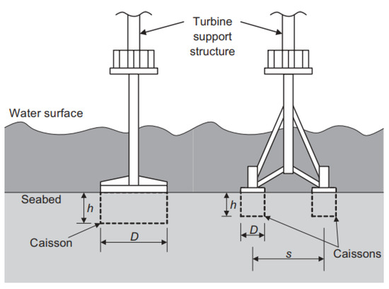
Figure 3.
Example of monopod and tripod suction caisson foundations [20].
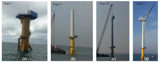
Figure 4.
Measurement framework consisting of four stages during construction: (a) stage I, (b) stage II, (c) stage III, and (d) stage IV.
Since the foundation cost reaches 20–40% of the total cost depending on water depth [21], it is economically very attractive to optimize the design of SBs. Lowering foundation cost is key to reducing the total cost for OWTs. Therefore, selecting a suitable OWTs foundation type and optimal design are the most important factors to lower the cost. As an example, there are two weather towers with different types of substructures constructed by The Korea Electric Power Corporation Research Institute (KEPCO RI). The first tower (HeMOSU-1) is supported by a jacket pile foundation; whereas the second tower (HeMOSU-2) is supported by a TSB foundation. The cost analysis showed that the TSB foundation requires half of the construction cost of jacket piles for the same seabed condition. Remarkably, the penetration of HeMOSU-2 into the TSB foundation was completed in 6 h, while HeMOSU-1 took two months to install [22]. This confirmed again that suction caissons are excellent solutions from construction and installation perspectives. Regarding the issue of cost optimization, not only the structural design of a substructure, but energy system equipment were also proposed. Mostafa Nazemi and his coworkers [23] proposed a comprehensive analytical architecture to model, characterize, and mitigate the general HILP hazards and earthquakes, while Yushuai Li et al. [24] investigated the adaptive and optimal control problem for a virtual synchronous generator (VSG). Using the proposed controller, the author can obtain the optimal control policy in a model-free fashion, which is the major advantage compared with the existing optimal control approaches used in VSG.
However, the cost is not the only issue concerning foundations. The development of a new concept of foundations also aims to enhance the resistance of the foundations. The bucket foundations supporting OWTs are subjected to a vertical load, horizontal load and overturning moment resulting from self-weight, wind, wave, current, etc. Hence, the vertical, horizontal and moment-bearing capacities must be investigated, and they can be determined by the simple method, the tangent intersection method [25], as shown in Figure 5, where two tangent lines along the initial and latter portions of the load–displacement curve are plotted, and the bearing capacity is the intersection point of these two lines. Although the foundation is not widely used in practical wind farms, its bearing capacity under variable loading conditions was investigated using model tests [26,27,28] and numerical modeling [29,30]. Considering that some of the offshore wind farms are located in earthquake areas, the study of the seismic behavior of SB is also one of the most vital engineering issues. In this study, some analyses were conducted to understand the responses of the proposed offshore wind turbine when supporting structures under seismic loads, wind load, and both of the two under scouring conditions. Finally, the fragility curve was used to compare the seismic performance between the proposed foundation and traditional TSB foundation.
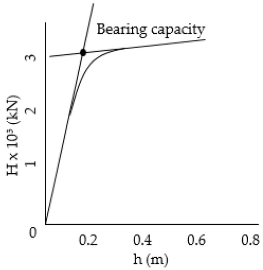
Figure 5.
Tangent intersection method for determining bearing capacity [31].
3. Development of Novel Pentapod Bucket
3.1. Limitation of Tripod Mode of the Suction Bucket on Shallow Muddy Seabed Conditions
As mentioned in the previous section, to fulfill the higher requirements of the foundation overturning resistance, the tripod concept was developed based on the principle of the monopod bucket. They present several benefits compared to other types of support structures. For instance, with respect to monopod bucket, tripods transfer loads to the soil in a different way and increase the interaction between the soil and bucket, allowing the foundation to be shallower and lighter than the monopod bucket. This section presents the challenges and limitations of the TSB foundation on the shallow muddy seabed, which is considered as a popular structure of seabed on the west coast of Gunsan, Korea (Table 1). Thus, the new concept of SB needs to be developed.

Table 1.
Soil profile of survey site.
Wind turbine structure remains stable by the balance between external force, self-weight (W) and ground reaction force (V). For simplicity, the external force acting on the OWTs only considers the wind thrust (F) (Figure 6). The equilibrium equation was presented in terms of vertical load, Equation (1), and moment, Equation (2), as below:
where b is the space between the buckets, and h is the height of the hub. From Equation (2), it can be concluded that there are two methods of reinforcing the overturning moment reaction. The first solution is to increase the space b between the buckets; the other way is to increase the ground reaction force (V). The ground reaction force (V) is proportional to the contact area of a bucket with surrounding soil. Thus, ground reaction force magnitude can be enhanced by extending the bucket diameter (D) or increasing the bucket height (L).
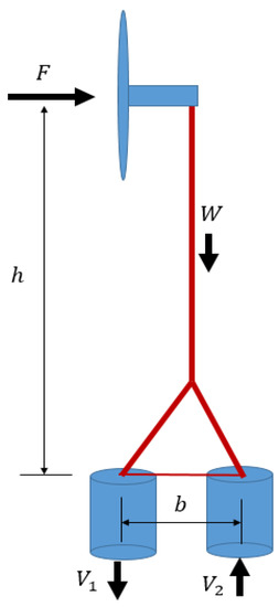
Figure 6.
Simplified loading mechanisms for suction-bucket-supported OWT.
Figure 7 shows an OWT with TSB in a shallow muddy seabed condition. A shallow muddy seabed with an average depth of around 7 m, was found on the west coast of Gunsan, lying on the rock bed (Figure 7). Hence, expanding the bucket length (L) is unfeasible, and thus limited to around 7 m. It is possible to increasing the bucket diameter to obtain larger bucket area as mentioned above. However, it is not easy to manufacture a bucket of a huge diameter more than 10 m. Moreover, increasing the bucket diameter inevitably closes the gap between the buckets, creating a group pile effect which is unfavorable to bearing capacity.
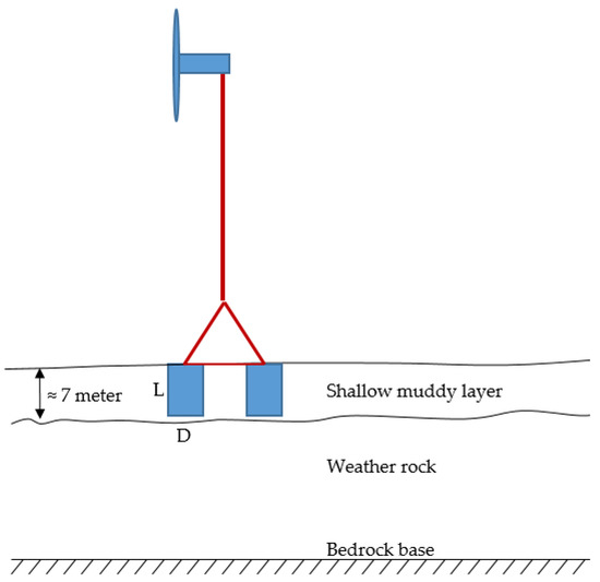
Figure 7.
Bucket height (L) was limited by the rock layer depth.
3.2. Derivation of Multi-Pod SB Kinematics
As the reasons were presented in Section 3.1, a new concept of SB foundation using more than three buckets was proposed. Figure 8 shows a top view of a variety of SB models and thrust direction with respect to turbine orientation. Supposing that the spacing R between each bucket and the wind turbine center (Figure 8a) is the same for all of multi-pod SB foundations, the direction of wind thrust, pull-out resistance (Vt) and compression resistance (Vc) are denoted in Figure 8. Accordingly, the resisting moment (MR) can be calculated using the load and the distance in each model as below:
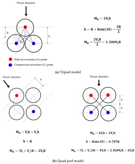
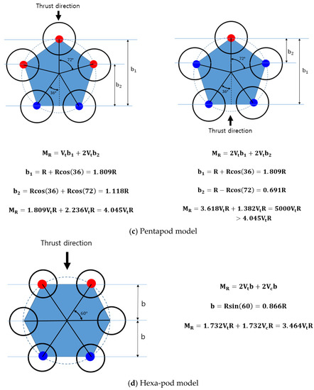
Figure 8.
Top view of multi-pod buckets.
The pull-out resistance (Vt) and compression resistance (Vc) of the single bucket were assumed to have the same values. By dividing the resisting moment by the value of (VtR), the dimensionless resisting moment was derived, as shown in Figure 9. It can be seen that the dimensionless resisting moment of the pentapod bucket is the highest. This means that if the bucket size and the space between the bucket and the wind turbine center are the same, the foundation model with the pentapod bucket is optimal in terms of the resisting moment.
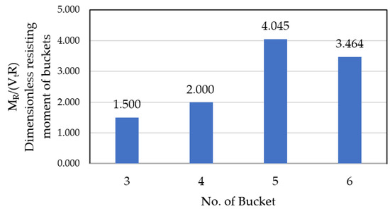
Figure 9.
Dimensionless resisting moment of buckets.
4. Performance Verification
4.1. Wind Turbine Model
The aim of this study is to propose an SB foundation solution suitable for shallow seabed conditions to support 5.5 MW capacity OWTs. The tower and substructure geometry is designed to ensure the necessary stiffness and tested under a variety of complex loading conditions in the design process. The details of the tower design are beyond the scope of this paper. Instead, a brief description is provided. The turbine tower has a hub height of 110.084 m above the mean sea level. The tower is tubular steel, which is composed of four sectional pieces with the largest diameter of 6 m and the smallest diameter of 5 m. The thickness of the tower varies across the height. The properties of the steel used for the tower and substructure are described in Table 2, while masses of tower components are given in Table 3. In order to account for the mass of the desk platform, boat landing, stair, flanges, etc., some concentrated mass is distributed along the body of the tower. Their relative positions to the mean sea level (M.S.L) and their weight are shown as in Table 4.
Table 2.
Steel properties.
Table 3.
Mass of tower components (kg).
Table 4.
Support structure node information.
4.2. Support Structure Model
The geological survey area was chosen as the west coast near Gunsan in Jeollabuk-do of Korea. The soil properties at this site are shown in Table 1. The pentapod suction bucket (PSB) foundation was chosen due to its advantages with this geological condition as discussed in Section 3. The single bucket of the PSB foundation has a diameter of 9 m and a length of 7 m. The thickness of the bucket wall is 25 mm. To verify the superior performance of PSB, it is compared with TSB which is composed of three buckets of 20 m diameter (Figure 10). The specifications of the two foundations are compared in Table 5.
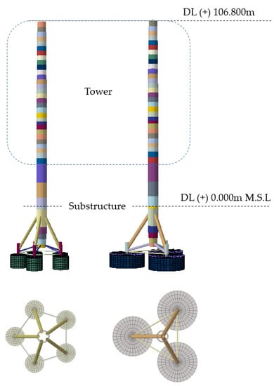
Figure 10.
Illustration of analysis models.
Table 5.
Substructure information.
4.3. Finite Element Model
The finite element program, Abaqus [32] software, was used for simulation. The soil model is 100 m in length and 30 m in height. The finite elements, C3D8R, are used for the soil medium. To achieve an adequate accuracy of the results and avoid the boundary condition effect, infinite elements (CIN3D8) were used to simulate the infinite extent of the soil, as shown in Figure 11. The size of the infinite elements must be considerably larger than the finite elements in the mesh. The tower model was simplified by using the equivalent mass for the hub–blade–nacelle assembly and lumping it at the hub height. To model the interaction between the bucket and soil, surface-to-surface contact pairs were used for outer and inner interactions where the normal and tangential behavior must be specified in Abaqus/CAE. A “hard” contact was used for the normal behavior. Regarding the tangential behavior, the penalty algorithm was chosen as the constraint enforcement method, and it was assumed to be isotropic with the friction coefficient, a value of µ = 0.5.

Figure 11.
Illustration of soil.
In this study, only horizontal earthquakes acting on the structure are considered. El Centro (1940), Ofunato (1978), and Hachinohe earthquakes (1968) (Figure 12) are chosen as input motions.
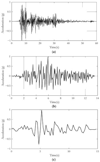
Figure 12.
Earthquake motions: (a) El Centro(1940); (b) Ofunato(1978); (c) Hachinohe(1968).
To investigate the behavior of the foundation under the influences of the marine environment, three load cases (case 1: seismic alone, case 2: wind alone, and case 3: a seismic-wind combination) were applied for OWTs in post-scour conditions. The thrust force was obtained by using GH-bladed, as shown in Figure 13. Table 6 shows the initial design factors for the 5.5 MW blade that was used as the input parameters of GH-bladed.
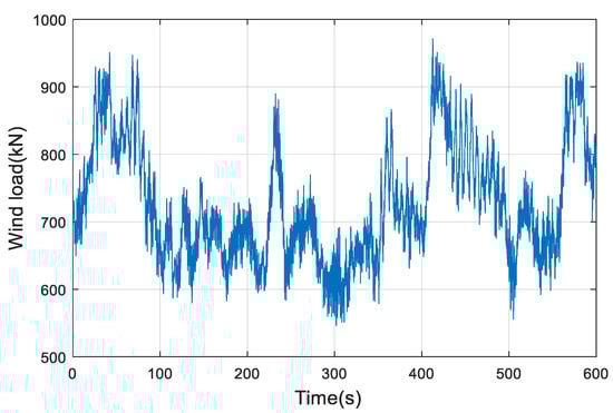
Figure 13.
Time history of wind thrust.
Table 6.
Basic design parameter of 5.5MW capacity OWTs.
4.4. Simulation of Scour Depth
Although there were many studies regarding the prediction and calculation of equilibrium scour depth of the marine and coastal structures, the calculation of the scour depth (SD) is still complex, time-consuming, and has much uncertainty. Therefore, this study does not consider equilibrium scour depth. Accordingly, the analysis will stop at the target total scour depth where structural response exceeds the defined damage state. Since this present study focused on verifying the responses of developed OWTs under various conditions and evaluating the change between pre-scour and post-scour conditions, the scour modeling was simplified by the removal of soil layer within the scour depth, as shown in Figure 14. Therefore, the development pattern and speed of local scour are not considered.
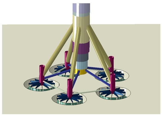
Figure 14.
Finite element model of scoured seabed.
4.5. Natural Frequency Analysis
The first natural frequency of all systems has a high impact on the dynamic behavior and stability of OWTs. A natural frequency analysis is performed to ensure the OWTs system frequency in a safe region. Figure 15 illustrated the design ranges for the natural frequency of 5.5 MW capacity OWTs. The first natural frequency of the system must not be in rotor frequency range (1P) or in the blade passing frequency ranges (3P), in order to avoid the resonance and can lie within three possible ranges: soft–soft, soft–stiff and stiff–stiff. Not only the rotor frequency, but excitation frequencies of waves and wind should be considered carefully. Accordingly, soft–soft is the range of frequency of wave action, and the stiff–stiff range will need a very stiff support structure; therefore, the structural frequency of the turbine is usually designed to fall within the soft–stiff region. The DNV code [33] suggests that the first natural frequency should be between a 1P-frequency +10% and 3P-frequency −10%. The first tower fore-aft and first tower side-to-side mode shapes of the tower are illustrated in Figure 16, and the frequencies according to the models are shown in Table 7. It can be seen that the first two natural frequencies of the two foundations are within the safe frequency range of 0.245–0.279 Hz.

Figure 15.
Design ranges for the fundamental frequency of 5.5 MW capacity turbine.
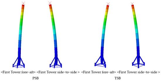
Figure 16.
Mode shapes.
Table 7.
First natural frequencies of SBs.
Offshore structures on a sandy seabed are always susceptible to scour, and so the effect of scour was also taken into account in this study. Table 8 presents the results of the natural frequency analysis corresponding to each scour depth. It is shown that, for the PSB foundation, the natural frequencies of the whole system are still within the target frequency range of 0.245–0.279 Hz; even the scour depth reaches 4 m, which is larger than half the height of SB (7 m). Specifically, the change in the first natural frequency due to different scour conditions is approximately 0.04–0.21%. This implies that scour has little influence on the first natural frequency of OWTs supported by the PSB foundation. Yu Yuan et al. [34] investigated the effects of scour on the stiffness of wide shallow bucket foundation and first natural frequency of offshore wind turbines, reaching the same conclusion. Table 8 also indicates that scour has a minor effect on the first natural frequency of TSB foundation, the change is approximately from 0.26 to 0.78%, respectively, from 1 to 4 m to SD. However, under SD of the 4 m condition, the first natural frequency is 0.24498 Hz, beyond the safe range of 0.245–0.279 Hz.
Table 8.
First natural frequency results under scour condition.
4.6. Scouring Fragility Analysis Approach
Fragility analysis is one such approach that uses discrete variables from the data of structural demands to establish the continuous probabilistic curve of the demands with respect to certain limit states. This paper focuses on assessing the vulnerability of a structure due to seismic and wind load under scour condition rather than proposing a new fragility analysis method. Accordingly, the maximum likelihood estimation (MLE) method was used in this study. A lognormal cumulative distribution function is often used to define a fragility function [35]:
where is the probability that an intensity measure of extreme environmental conditions will cause the structural demands exceeding a damage state (k). If the structure incurs damage, the probability values of 1 will be set corresponding to the high risks of exceeding; otherwise, it is set to 0 to indicate that there is almost no exceeding probability. The variable is the standard normal cumulative distribution function (CDF), is damage level, is the median of the fragility function and is the standard deviation.
Considering an incremental dynamic analysis of n environmental action, the likelihood of the entire data set being observed can be expressed as:
where depending on whether or not the structure sustains the state of damage under the intensity measure of environmental action; Π is the product over i values form 1 to n. Two fragility parameters, and , are obtained by maximizing the likelihood function as:
The procedure of calculating the fragility curves in this study is summarized as:
- (1)
- Build the finite element model with the proposed SB foundation and verify it by modal analysis;
- (2)
- Selecting the loading case. Using the earthquake motion, wind loading, and three load cases are mentioned in Section 4.3 as the input motions for conducting a dynamic simulation to obtain demand of the structure;
- (3)
- Defining the damage state and solve Equation (5). In this study, the top displacements at SB were used to find the fragility curves and the criteria displacement at the top of SB was set to 38 mm, which is defined for the bridge foundation in the AASHTO LRFD Bridge Design Specification;
- (4)
- Finally, calculate the fragility curves using Equation (3).
As mentioned previously, the displacement at the bucket top was used to compare the dynamic responses of the support structure, where various stages of scour occurred. For example, the SB Offshore Wind Turbine (PSB and TSP), excited by earthquake motion alone, were simulated. With a PGA ranging from 0.1 to 0.5 g, the dynamic responses of the wind turbine, in terms of top displacement at SB, are shown in Figure 17. In all seismic motions and PGAs, TSB had greater displacement than PSB. Figure 18 shows the seismic response (PGA = 0.1 g) of SB with different scour depths. Based on the obtained dynamic responses and the defined damage states, fragility curves of the wind turbine in different conditions were calculated. Fragility curve of the TSB and PSB foundations were compared in Figure 19. It can be seen that the fragility curves of the TSB are always to the left of the PSB at the same scour depth level. This means that, under scour conditions, the PSB foundation shows better seismic performance than TSB, although the PSB is made of approximately 64% steel of the equivalent TSB support structure. Regarding the second point, one can see from the figure that, when the scour is large, e.g., 4 m, the probability of damage goes up very quickly at around PGA of 0.05 g for TSB and PGA of 0.10 g for PSB. It means that deep scour may be vulnerable to an earthquake.
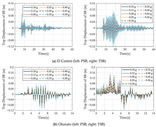

Figure 17.
Top displacement of SB under earthquake motion.
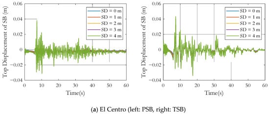
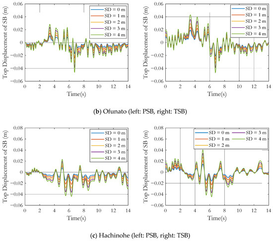
Figure 18.
Top displacement of SB with scour under earthquake.
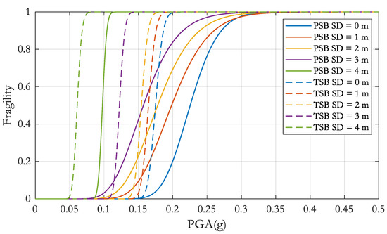
Figure 19.
Comparison of seismic fragility curves.
4.7. Scouring Fragility Analysis Approach
To investigate the effects of the joint action of environmental wind on the seismic fragility curves, the thrust force generated at the rated wind speed of 13 m/s was applied to the hub height during of 100 s. Three load cases (case 1: seismic load, case 2: wind load, and case 3: combination of the both) are considered for OWTs under the scour condition. Figure 20 and Figure 21 show displacement time histories at the top of SB under different external excitations. Figure 20 shows the peak response corresponding to load case 2 under scour conditions. It can be seen that, for both models, PSB and TSB, the effect of wind on the top displacement of SB is relatively small. Namely, even though the scour depth is assumed a simulation up to 7 m, the peak response is around the value of 0.04 m, note that the critical displacement used in this study is 0.038 m. Meanwhile, with load case 3, under scour conditions, the top displacement of SB increased violently as the scour depth increased, the peak response at SD of 4 m increased to more than twice the pre-scour condition for all earthquake motion, exceeding the critical displacement of 0.038 m as shown in Figure 21. Figure 22 shows the comparison of the SB response for the three load cases with no scour. The corresponding peak responses are also listed in Table 9. For all conditions, it is clear that the top displacement of SB caused by the wind load alone is clearly smaller than that caused by the seismic load alone. It decreased from a minimum of 34.0% to a maximum of 62.3% in PSB and from a minimum of 30.1% to a maximum of 56.1% in TSB. In the case of the seismic–wind load combination, the peak response decreased from a minimum of 0.8% to a maximum of 4.8% in TSB. This implies that the wind acting on the OWTs has a minor impact on the top displacement of SB in operating conditions and the top displacement of SB is mainly dominated by the seismic load. This is also confirmed again in Figure 23. Fragility curves were redrawn with respect to not by PGA but by scour depth in Figure 23. Therefore, it can be called as scouring fragility. In drawing the figure, the design seismic load is set to 0.1 PGA. The comparison of the scouring fragility under the three loading cases shows that the OWTs suffered from the highest probability of damage under seismic load alone (case 1) and the fragilities by the joint action of seismic and wind load (case 3) were slightly decreased compared to the loading case 1. The probability of exceeding the damage state of OTWs under wind load (case 2) was far smaller than the results from case 1. In Figure 23, it is interesting to find that the fragilities of the PSB foundation were smaller than those of the TSB foundation for all loading cases.
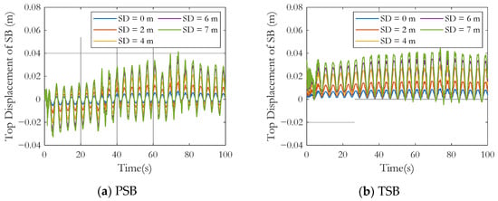
Figure 20.
Top displacement of SB under joint action of wind alone and scour condition.
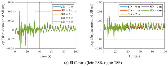
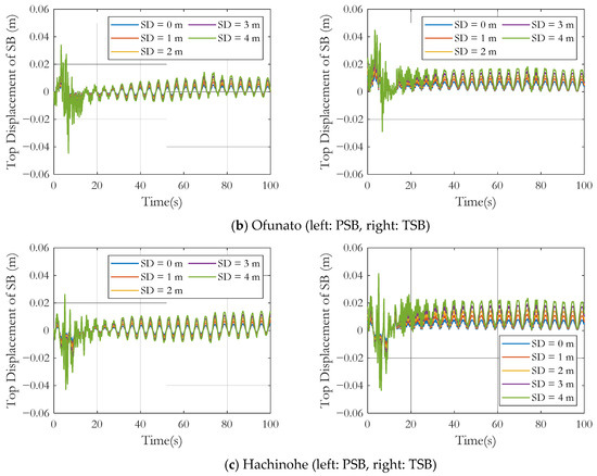
Figure 21.
Top displacement of SB under joint action of seismic–wind combination and scour condition.
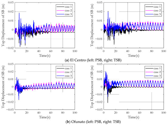
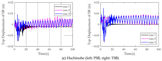
Figure 22.
Comparison of top displacement of SB with different environmental conditions.
Table 9.
Maximum top displacement of SB under different condition.

Figure 23.
Scouring fragility curves.
5. Conclusions
This study proposed a PSB foundation as the feasible choice of foundation solution, suitable for locations with shallow muddy seabed conditions. For the combined effect of the post-scour, earthquake, and wind load, some analysis was carried out. The following conclusions were obtained from this study:
- (1)
- If the bucket size (L, D) and the space between the bucket and the wind turbine center (R) are assumed to be similar, the foundation model with the PSB is the optimal in terms of the dimensionless resisting moment;
- (2)
- The scour has a minor effect on the natural frequency of the OWTs system. Specifically, with the proposed PSB model, the first natural frequency of the system is reduced by about 0.21%, even with scour depth of 4m. The effect of this is small because the lateral stiffness of the wide shallow bucket is large. This is in good agreement with previous studies;
- (3)
- Under scouring conditions, the stability of the foundation deteriorates significantly. Specifically, the displacement at the SB level increases gradually as the depth of scouring increases. However, wind acting on the OWTs has a minor impact on the top displacement of SB in operating conditions, and the top displacement of SB is mainly dominated by seismic load. Additionally, the top displacement of SB caused by the seismic wind combination is clearly less than that caused by the seismic load alone;
- (4)
- From the analysis, PSB clearly has a better performance compared with the TSB. PSB not only saves materials (the total mass is reduced to only 64% of TSB), but also shows a better seismic performance in bearing capacity.
Since all issues cannot be resolved in this study, other complex problems, such as the effect of the speed and development of local scour, different shallow seabed properties and other external forces, such as a wave, etc., need to be performed in order to develop a more comprehensive understanding of this foundation behavior.
Author Contributions
Conceptualization, D.-V.N. and D.-H.K.; methodology, D.-V.N. and D.-H.K.; software, D.-V.N. and Y.-J.K.; validation, D.-H.K.; formal analysis, D.-V.N.; investigation, Y.-J.K.; data curation, D.-V.N., Y.-J.K. and D.-H.K.; writing—original draft preparation, D.-V.N.; writing—review and editing, D.-V.N., Y.-J.K., and D.-H.K.; supervision, D.-H.K. All authors have read and agreed to the published version of the manuscript.
Funding
This research received no external funding.
Institutional Review Board Statement
Not applicable.
Informed Consent Statement
Not applicable.
Data Availability Statement
Not applicable.
Acknowledgments
This research was supported by Basic Science Research Program through the National Research Foundation of Korea (NRF) funded by the Ministry of Education (No. 2020R1F1A1076884).
Conflicts of Interest
The authors declare no conflict of interest.
References
- Scharff, R.; Siems, M. Monopile foundations for offshore wind turbines—Solutions for greater water depths. Steel Constr. 2013, 6, 47–53. [Google Scholar] [CrossRef]
- De, C.; Kai, H.; Lijun, H. Comparison of Structural Properties between Monopile and Tripod Offshore Wind-Turbine Support Structure. Adv. Mech. Eng. 2013, 2013, 1756849. [Google Scholar]
- Georgia, M.; Anastasios, P.; Dimosthenis, B.; Charis, J.G.; Christos, P.G. Design of Monopile and Tripod Foundation of Fixed Offshore Wind Turbine via Advanced Numerical Analysis. In Proceedings of the 8th GRACM International Congress on Computation Mechanics, Volos, Greek, 12–15 July 2015. [Google Scholar]
- Kallehave, D.; Byrne, B.W.; LeBlanc Thilsted, C.; Mikkelsen, K.K. Optimization of monopiles for offshore wind turbines. Philos. Trans. R. Soc. Lond. A 2015, 373, 20140100. [Google Scholar] [CrossRef] [Green Version]
- Tasan, H.E.; Yilmaz, S.A. Effects of installation on the cyclic axial behaviour of suction buckets in sandy soils. Appl. Ocean. Res. 2019, 91, 101905. [Google Scholar] [CrossRef]
- Latini, C.; Zania, V. Dynamic lateral response of suction caissons. Soil Dyn. Earthq. Eng. 2017, 100, 59–71. [Google Scholar] [CrossRef] [Green Version]
- Bagheri, P.; Yoon, J.C.; Park, D.; Kim, J.M. Numerical Analysis of Suction Bucket Foundations Used for Offshore Wind Turbines. In Proceedings of the 1st Vietnam Symposium on Advances in Offshore Engineering, Ha Noi, Viet Nam, 1–3 November 2018; VSOE 2018, Lecture Notes in Civil Engineering. Springer: Singapore, 2019; Volume 18. [Google Scholar]
- Achmus, M.; Akdag, C.; Thieken, K. Load-bearing behavior of suction bucket foundations in sand. Appl. Ocean. Res. 2013, 43, 157–165. [Google Scholar] [CrossRef]
- Ding, H.; Liu, Y.; Zhang, P.; Le, C. Model tests on the bearing capacity of wide-shallow composite bucket foundations for offshore wind turbines in clay. Ocean. Eng. 2015, 103, 114–122. [Google Scholar] [CrossRef]
- Thieken, K.; Achmus, M.; Schröder, C. On the behavior of suction buckets in sand under tensile loads. Comput. Geotech. 2014, 60, 88–100. [Google Scholar] [CrossRef]
- Bang, S.; Preber, T.; Cho, Y.; Thomason, J.; Karnoski, S.R.; Taylor, R.J. Suction piles for mooring of mobile offshore bases. Mar. Struct. 2000, 13, 367–382. [Google Scholar] [CrossRef]
- Byrne, B.; Houlsby, G.; Martin, C.; Fish, P. Fish Suction caisson foundations for offshore wind turbines. Wind Eng. 2002, 26, 145–155. [Google Scholar] [CrossRef]
- Hogevorst, J. Field Trials with Large Diameter Suction Piles. In Proceedings of the Offshore Technology Conference, Houston, TX, USA, 5–8 May 1980. [Google Scholar]
- Tjelta, T.I.; Guttormsen, T.R.; Hermstad, J. Large-Scale Penetration Test at a Deepwater Site. In Proceedings of the 18th Offshore Technology Conference, Houslon, TX, USA, 5–8 May 1986. [Google Scholar]
- Bye, A.; Erbrich, C.; Rognlien, B.; Tjelta, T.I. Geotechnical Design of Bucket Foundations. In Proceedings of the 27th Annual OTC, Houston, TX, USA, 1–4 May 1995. [Google Scholar]
- Koteras, A.K.; Ibsen, L.B.; Clausen, J. Seepage study for suction installation of bucket foundation in different soil combinations. In Proceedings of the 26th International Ocean and Polar Engineering Conference, Rhodos, Greece, 26 June–2 July 2016; pp. 697–704. [Google Scholar]
- Houlsby, G.T.; Ibsen, L.Β.; Byrne, B.W. Suction caissons for wind turbines. Front. Offshore Geotech. 2005, 44, 75–93. [Google Scholar] [CrossRef]
- Seo, Y.-H.; Ryu, M.S.; Oh, K.-Y. Dynamic Characteristics of an Offshore Wind Turbine with Tripod Suction Buckets via Full-Scale Testing. Complexity 2020, 2020, 3079308. [Google Scholar] [CrossRef]
- Aspizua, L. Offshore Foundation-A Challenge in the Baltic Sea. Master’s Thesis, Halmstad University, Halmstad, Sweden, 18 June 2015. [Google Scholar]
- Houlsby, G.T.; Kelly, R.; Huxtable, J.; Byrne, B.W. Field trials of suction caissons in sand for offshore wind turbine foundations. Géotechnique 2006, 56, 3–10. [Google Scholar] [CrossRef]
- Swart, R.; Coppens, C.; Gordjin, H.; Piek, M.; Ruyssenaars, P.; Schrander, J.J.; Hoogwijk, M.; Papalexandrou, M.; Horalek, J. Europe’s Onshore Andoffshore Wind Energy Potential: An Assessment of Environmental and Economic Constraints. (No. 6/2009); European Environment Agency: København, Denmark, 2009. [Google Scholar] [CrossRef]
- Oh, K.Y.; Nam, W.; Ryu, M.S.; Kim, J.Y.; Epureanu, B.I. A review of foundations of offshore wind energy convertors: Current status and future perspectives. Renew. Sustain. Energy Rev. 2018, 88, 16–36. [Google Scholar] [CrossRef]
- Nazemi, M.; Dehghanian, P. Seismic-Resilient Bulk Power Grids: Hazard Characterization, Modeling, and Mitigation. IEEE Trans. Eng. Manag. 2020, 3, 614–630. [Google Scholar] [CrossRef]
- Li, Y.; Gao, W.; Yan, W.; Huang, S.; Wang, R.; Gevorgian, V.; Gao, D.W. Data-driven Optimal Control Strategy for Virtual Synchronous Generator via Deep Reinforcement Learning Approach. J. Mod. Power Syst. Clean Energy 2021, 9, 919–929. [Google Scholar] [CrossRef]
- Mansur, C.I.; Kaufman, J.M. Pile tests, low-sill structure, Old River, Louisiana. J. Soil Mech. Found. Div. 1956, 82, 1–33. [Google Scholar] [CrossRef]
- Zhu, B.; Kong, D.; Chen, R.; Kong, L.; Chen, Y. Installation and lateral loading tests of suction caissons in silt. Can. Geotech. J. 2011, 48, 1070–1084. [Google Scholar] [CrossRef]
- Gao, Y.; Qiu, Y.; Li, B.; Li, D.; Sha, C.; Zheng, X. Experimental studies on the anti-uplift behavior of the suction caissons in sand. Appl. Ocean. Res. 2013, 43, 37–45. [Google Scholar] [CrossRef]
- Wang, X.; Zeng, X.; Li, J. Vertical performance of suction bucket foundation for offshore wind turbines in sand. Ocean. Eng. 2019, 180, 40–48. [Google Scholar] [CrossRef] [Green Version]
- Gourvenec, S. Effect of embedment on the undrained capacity of shallow foundations under general loading. Géotechnique 2008, 58, 177–185. [Google Scholar] [CrossRef]
- Liu, M.; Yang, M.; Wang, H. Bearing behavior of wide-shallow bucket foundation for offshore wind turbines in drained silty sand. Ocean. Eng. 2014, 82, 169–179. [Google Scholar] [CrossRef]
- Kim, S.-R.; Hung, L.C.; Oh, M. Group effect on bearing capacities of tripod bucket foundations in undrained clay. Ocean. Eng. 2014, 79, 1–9. [Google Scholar] [CrossRef]
- Abaqus, in Dassault Systemes Simulia Corporation. 2020. Available online: https://abaqus-docs.mit.edu/2017/English/SIMACAEEXCRefMap/simaexc-c-docproc.htm (accessed on 10 January 2022).
- Det Norske Veritas. Design of Offshore Wind Turbine Structures; Offshore Standard DNV-OS-J101; Det Norske Veritas: Høvik, Norway, 2014. [Google Scholar]
- Yuan, Y.; Liu, R.; Lian, J.; Fu, D.; Zhang, H.; Wang, Y. Effects of Scour on Stiffness of Wide Shallow Bucket Foundation and 1st Natural Frequency of Offshore Wind Turbine. In Proceedings of the 29th International Ocean and Polar Engineering Conference, ISOPE-I-19-281, Honolulu, HI, USA, 16 June 2019. [Google Scholar]
- Kim, D.H.; Lee, S.G.; Lee, I.K. Seismic fragility analysis of 5 MW offshore wind turbine. Renew. Energy 2014, 65, 250–256. [Google Scholar]
Publisher’s Note: MDPI stays neutral with regard to jurisdictional claims in published maps and institutional affiliations. |
© 2022 by the authors. Licensee MDPI, Basel, Switzerland. This article is an open access article distributed under the terms and conditions of the Creative Commons Attribution (CC BY) license (https://creativecommons.org/licenses/by/4.0/).