Article

Faulty Line Selection Method Based on Comprehensive Dynamic Time Warping Distance in a Flexible Grounding System

School of Electrical and Electronic Engineering, Shandong University of Technology, Zibo 255000, China
*
Author to whom correspondence should be addressed.
Energies 2022, 15(2), 471; https://doi.org/10.3390/en15020471
Submission received: 17 December 2021 / Revised: 31 December 2021 / Accepted: 5 January 2022 / Published: 10 January 2022
(This article belongs to the Section F1: Electrical Power System)

Abstract

:
A flexible grounding system is a system in which the neutral point of the power supply is grounded via the arc suppression coil in parallel with a low-resistance resistor. When operating normally or a temporary ground fault occurs, the arc suppression coil is used for grounding, whereas the small resistance is switched on when a permanent ground fault occurs. At present, the problem of low protection sensitivity when a high-resistance ground fault occurs in a flexible grounding system has not been solved yet. According to the characteristics of low waveform similarity between the faulty line and the non-faulty line when a single-phase grounding fault occurred, a new faulty line selection method based on a combination of Dynamic Time Warping (DTW) distance and the transient projection method is proposed in this paper. Firstly, the fault transient signal is extracted by a digital filter as a basis for faulty line selection. Secondly, the transient zero-sequence current of each line is projected onto the busbar transient zero-sequence voltage, and the projected DTW distance of each line is calculated. Finally, according to the calculation formula of waveform comprehensive similarity coefficient, the Comprehensive DTW (CDTW) distance is obtained, and the top three CDTW distance values are selected to determine the faulty line. If the maximum value is greater than the sum of the other two CDTW distance values, the line corresponding to the maximum value is judged as the faulty line; otherwise, it is judged as a busbar fault. The simulation results based on MATLAB/Simulink and field data test show that the method can accurately determine the faulty line under diverse fault conditions.

1. Introduction

In China, the neutral point ungrounded or grounded through the arc suppression coil is widely used in the power distribution network [1]. In the resonant grounding system, the inductive current of the arc suppression coil is used to compensate for the capacitive current to extinguish the arc. However, when a permanent fault occurs, the arc suppression coil will increase the difficulty in selecting the faulty line and in clearing the fault quickly and decrease the service life of the cable [2,3]. Compared with the neutral point grounded via arc suppression coil, in the neutral point grounded via a small resistance system, when a permanent ground fault occurs, the relay protection can act quickly to clear the fault due to the large fault current. However, the low-resistance grounding mode will also bring some problems, such as the fault current being too large and the reliability of the power supply being low due to the frequent activation of the protection device [4]. The flexible grounding mode of the arc suppression coil paralleled with a small resistance combines the advantages of the arc suppression coil grounding and the low-resistance grounding mode, which has developed rapidly and is quickly applied to the distribution network. However, when the transition resistance exceeds 400 Ω, the zero-sequence current of the faulty line will not increase significantly after the low-resistance is switched on, which might reduce the low accuracy of faulty line selection [5]. At present, the failure of relay protection when a high-resistance grounding fault occurs in a flexible grounding system has not been resolved yet.
In view of the ground fault protection problem that occurred in flexible grounding systems, most of the relay protection schemes currently used are the same as those commonly used in low-resistance grounding systems. Most protection schemes using transient information focus on the wavelet analysis method [6] and transient energy-based methods [7]. However, when a high-resistance grounding fault occurs, the transient information caused by the fault is not obvious and is difficult to extract, which results in low sensitivity of the faulty line selection method based on transient information, and even results in faulty line selection failure. In order to improve the sensitivity of the protection action when a single-phase high-resistance grounding occurs in the flexible grounding system, [8] proposed a method that uses the changes of the zero-sequence current of each line and the zero-sequence voltage of the busbar before and after the small resistance switched on. Taking the phase difference change between the line zero-sequence current and the busbar zero-sequence voltage as the line selection criterion, the maximum value of the transition resistance detection is up to 3000 Ω. Literature [9] presented a method that uses the zero-sequence voltage and current corresponding to the zero-sequence active power direction as the faulty line selection criterion. The ability to detect the transition resistance is about 500 Ω. A fault location method using the change of line zero-sequence admittance before and after switching on the parallel small resistance is proposed in the literature [10], reflecting the ability to detect transition resistance is about 3000 Ω. A protection method that adaptively adjusts the action setting value of the zero-sequence current according to the magnitude of the zero-sequence voltage is presented in the literature [11], and the transition resistance of 1000 Ω could be detected. Literature [12] proposed a method based on the comparison between the neutral point current and the zero-sequence current reflecting the ability to detect the transition resistance is up to 3000 Ω.
This paper analyzes the characteristics of the zero-sequence current of each line and the zero-sequence voltage of the busbar after the small resistance parallel to the arc suppression coil is switched on and proposes a faulty line selection method based on the Comprehensive Dynamic Time Warping (CDTW) distance. The transient zero-sequence current of the line and the transient zero-sequence voltage of the busbar are used as characteristic quantities, which are subjected to transient projection processing for establishing the faulty line selection criterion combined with DTW distance. This paper also discusses the influence of the access of renewable energy power sources on the results of faulty line selection [13,14,15]. The effectiveness of the method is verified by the results of MATLAB/Simulink simulation. The main contributions of this paper are summarized as follows:
  • Able to determine the faulty line or busbar fault under diverse fault conditions;
  • Applicable for single-phase grounding fault in distribution network with renewable energy sources connected;
  • Applicable for high-resistance grounding fault detection, and the ability to detect transition resistance is up to 5000 Ω;
  • Under extreme fault conditions, the faulty line selection accuracy of the method proposed in this paper is higher than that of the existing traditional methods.

2. Materials and Methods

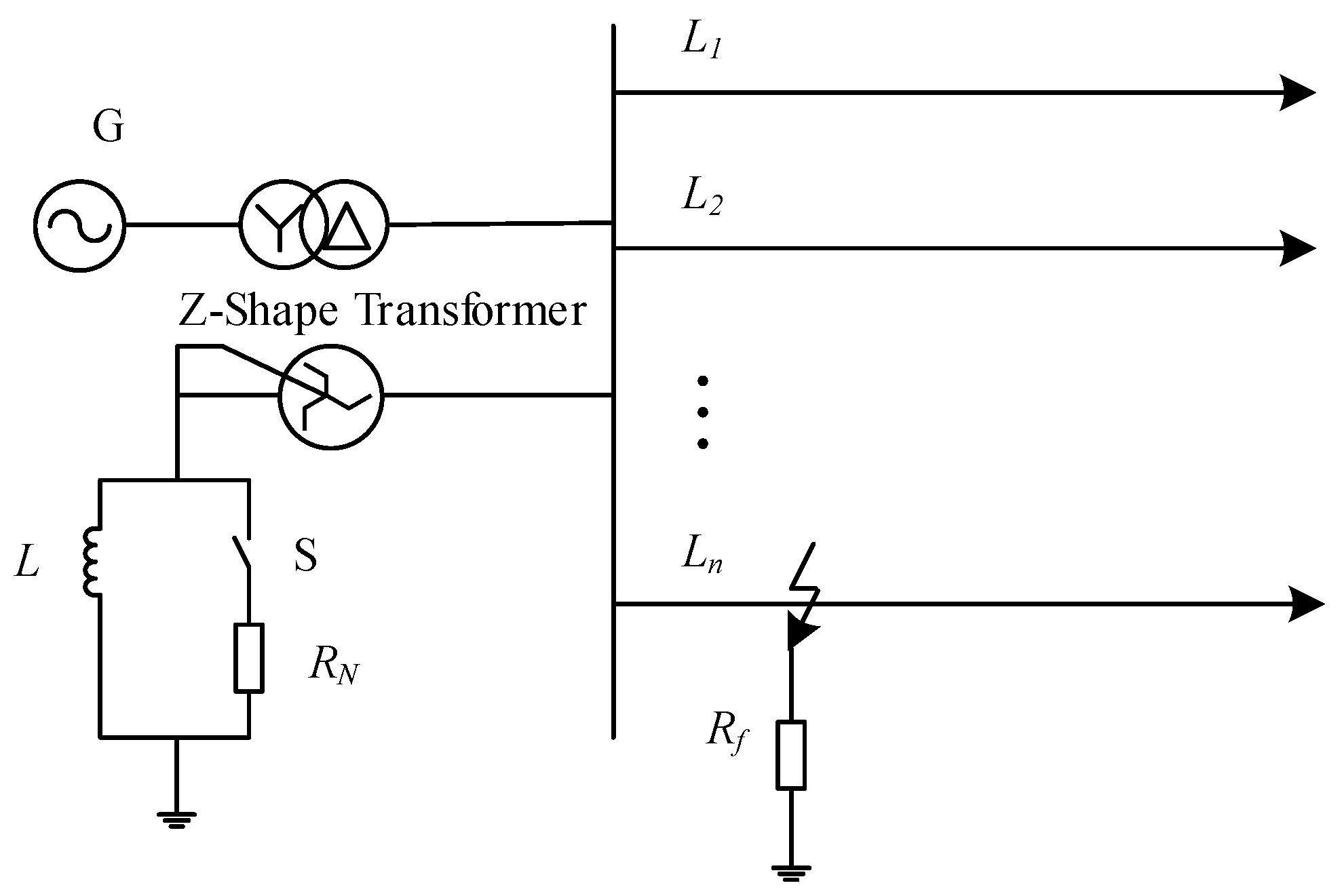
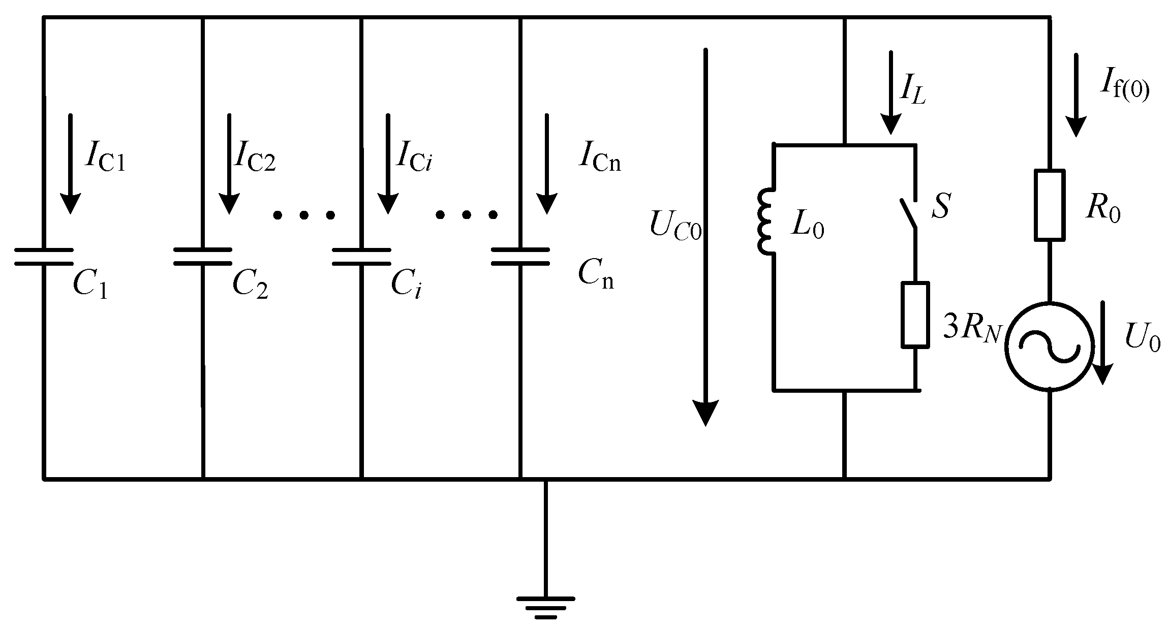
2.1. Transient Current Characteristics of Single-Phase Grounding Fault in Flexible Grounding System

The single-phase grounding fault diagram of a 10 kV flexible grounding system is shown in Figure 1. We assume that the system includes n lines, the line impedance is ignored, the three components are symmetrical, a single-phase grounding fault occurred on line n, and Rf is the transition resistance at the fault point. L is the inductance of the arc suppression coil, and RN is a small resistance connected parallel to the arc suppression coil (set to the commonly used 10 ohms in this paper). When switch S is switched off, the neutral point is grounded via arc suppression coil; when switch S is switched on, the neutral point is grounded via arc suppression coil with parallel small resistance.
The zero-sequence equivalent circuit diagram of a single-phase grounding fault in the flexible grounding system is shown in Figure 2. Ci (i = 1, 2, …, n−1) is the zero-sequence distributed capacitance of the non-faulty line, Cn is the zero-sequence distributed capacitance of the faulty line, L0 is the equivalent inductance of the arc suppression coil, R0 is the equivalent zero-sequence resistance of the transition resistance, UC0 is the zero-sequence voltage of the busbar, U0 is the zero-sequence equivalent voltage at the fault point, IL is the equivalent zero-sequence current of the branch of arc suppression coil paralleled with a small resistance, and If(0) is the zero-sequence current of the faulty line.
By analyzing Figure 2, the following formulas can be obtained:
U C 0 = U 0 + I f ( 0 ) R 0
I C i = C i d U C 0 d t
I f ( 0 ) = - ( I L + i = 1 n I C i )
From Equation (1), we can obtain the conclusion that when a single-phase grounding fault occurs in a flexible grounding system, the zero-sequence voltage of the busbar, UC, decreases due to the voltage drop across the transition resistance at the fault point. When a high-resistance grounding fault occurs with a transition resistance between several hundred ohms and several thousand ohms, the zero-sequence voltage value of the busbar is lower than that of a metallic grounding fault [16].
It can be seen from Equation (2) that the zero-sequence current at the outlet of a non-faulty line is only related to the line-to-ground capacitance, Ci, and the zero-sequence voltage of the busbar, UC. When the zero-sequence voltage of the busbar is exactly the same, the waveform of the zero-sequence current of the non-faulty line is approximately the same.
From Equation (3), the conclusion that the zero-sequence current at the outlet of the faulty line is composed of the zero-sequence current of the non-faulty line and the neutral grounded line can be obtained. Comparing Equation (2) and Equation (3), we can notice that a big difference in the zero-sequence current between the faulty line and the non-faulty line.

2.2. Faulty Line Selection Method Using CDTW Distance

2.2.1. The Principle of DTW Distance

Suppose there are two time series, T = { t 1 t 2 t m } and R = { r 1 r 2 r n } , and the lengths of which are m and n, respectively. Thus, a m × n distance square matrix, D, is constructed as follows:
D = [ d ( t 1 , r n ) d ( t 2 , r n ) d ( t m , r n ) d ( t 1 , r 2 ) d ( t 2 , r 2 ) d ( t m , r 2 ) d ( t 1 , r 1 ) d ( t 2 , r 1 ) d ( t m , r 1 ) ]
The expression of element d ( t i , r j ) (i = 1, 2, …, m. j = 1, 2, …, n) in D is d ( t i , r j ) = ( t i - r j ) 2 , which represents the square of the distance from ti to rj.
The DTW distance is an optimal warping path selected in the distance matrix, i.e., W = w 1 , w 2 , w l , , w k , where w l = d ( t i , r j ) . The time series T of length m is non-linearly mapped to the time series R of length n, and the DTW distance of the two time series, T and R, is obtained as follows:
DTW ( T , R ) = min ( i = 1 k w i )
DTW ( T , R ) can reflect the degree of difference between the two time series T and R. The larger the value of DTW ( T , R ) , the greater the degree of difference between the time series T and R.
The path of DTW distance should be selected to meet the following three constraints:
(1)
Boundary conditions
The sequence of the time series should not be changed, i.e., the starting point of the path should be at path w 1 = d ( t 1 , r 1 ) and the ending point should be at path w k = d ( t m , r n ) .
(2)
Monotonicity
For any point except the starting point and the ending point, w l = d ( t i , r j ) , the next point, w l + 1 = d ( t i + 1 , r j + 1 ) , of the warping path should satisfy the condition of t i + 1 - t i 0 and r j + 1 - r j 0 .
(3)
Continuity
The DTW path can only proceed along adjacent points, namely w l = d ( t i , r j ) . For the next point, w l + 1 = d ( t i + 1 , r j + 1 ) , the condition of t i + 1 - t i 1 and r j + 1 - r j 1 should be satisfied.
The DTW path can be expressed as P = { P 1 , P 2 , , P s , , P k } , where k represents the total number of elements (shadow squares in the Figure 3) in the path. The element Ps is the coordinate of the sth point on the path, P s = ( i , j ) . It means that ti in the sequence T corresponds to rj in the sequence R, and the distance between ti and rj is d ( P s ) = d ( i , j ) = | t i - r j | .
Due to the high sensitivity of the DTW distance and its strong resistance to synchronization errors [17], it can be used to distinguish the waveform similarity. The DTW distance is to bend two time series and use the dynamic programming idea to obtain the optimal curved path of the two series so as to minimize the distance between the two series along the path [18]. Generally, the cumulative value of this path is used to weigh the degree of sequence approximation.
The DTW distance has been used in the non-solidly neutral grounding system to select and locate the single-phase grounding fault. This paper combines the comprehensive similarity coefficient and the DTW distance to obtain the CDTW distance and applies it to the flexible grounding system.
When a single-phase grounding fault occurs in a flexible grounding system, the magnitude and phase difference of the zero-sequence current between non-faulty lines is small, i.e., the waveform similarity is high, and the value of DTW ( T , R ) is small. However, the magnitude of the zero-sequence current of the faulty line is much larger than that of the non-faulty line, and their polarity is opposite, which would cause the waveform similarity to be low and the DTW ( T , R ) value to be relatively large. Therefore, when a single-phase grounding fault occurs, the value of DTW distance among the outgoing lines can be used to determine the faulty line.

2.2.2. Comprehensive Similarity Coefficient of Waveform

Perform the DTW calculation on N outgoing lines pairwise, and the DTW distance matrix M is obtained as follows:
M = [ m 11 m 12 m 1 j m 1 N m 21 m 22 m 2 j m 2 N m i 1 m i 2 m i j m i N m N 1 m N 2 m N j m N N ]
where mij means the DTW distance between line i and line j.
Due to a large number of outgoing lines in the distribution system, the DTW distance matrix is not suitable for the line selection criterion. Therefore, a comprehensive similarity coefficient is proposed to simplify the DTW distance matrix as the line selection criterion [19]. The comprehensive similarity coefficient of line i in the paper is defined as:
c i = 1 N - 1 ( j = 1 N m i j - m i j max )
In Equation (7), mij max is the maximum DTW distance among line i to all other lines.

2.2.3. Waveform Processing Method of Transient Zero-Sequence Current

When a high-resistance grounding fault occurs in a flexible grounding system, the difference in fault current between the faulty line and the non-faulty line will be reduced, which may affect the result of fault line selection. Therefore, the fault signal should be amplified to increase the line selection accuracy. When a high-resistance grounding fault occurs, the amplitude of zero-sequence current will decrease as the transition resistance increases. Compared with the zero-sequence current, the fault characteristics of the zero-sequence voltage are more obvious when the ground resistance is high, and its anti-interference ability is stronger. Therefore, combined with the characteristics of the transient zero-sequence voltage, the low detection sensitivity due to the small zero-sequence current during high-resistance grounding fault can be improved.
The projection vector diagram of the line zero-sequence current on the busbar zero-sequence voltage is shown in Figure 4. The angle between vector U ˙ and vector I ˙ is α, P is the projected value of I ˙ on U ˙ , and the corresponding projection vector is P ˙ .
From Figure 4, the expression of cos α , P, and P ˙ can be obtained as shown in Equation (8).
{ cos α = U ˙ I ˙ | U ˙ | | I ˙ | P = | I ˙ | cos α P ˙ = U ˙ P | U ˙ |
By analyzing the variables in Equation (8), we can obtain the projection of I ˙ on U ˙ .
P ˙ = U ˙ U ˙ I ˙ | U ˙ | 2
where U ˙ I ˙ is the inner product of vectors U ˙ and I ˙ , and the projection of the transient zero-sequence current of the line on the transient zero-sequence voltage of the busbar can be calculated by Equation (9) [20].
The transient projection method was previously used in the neutral non-effectively grounding system and achieved good results. This paper will use the transient projection method to pre-process the fault data obtained in the flexible grounding system.

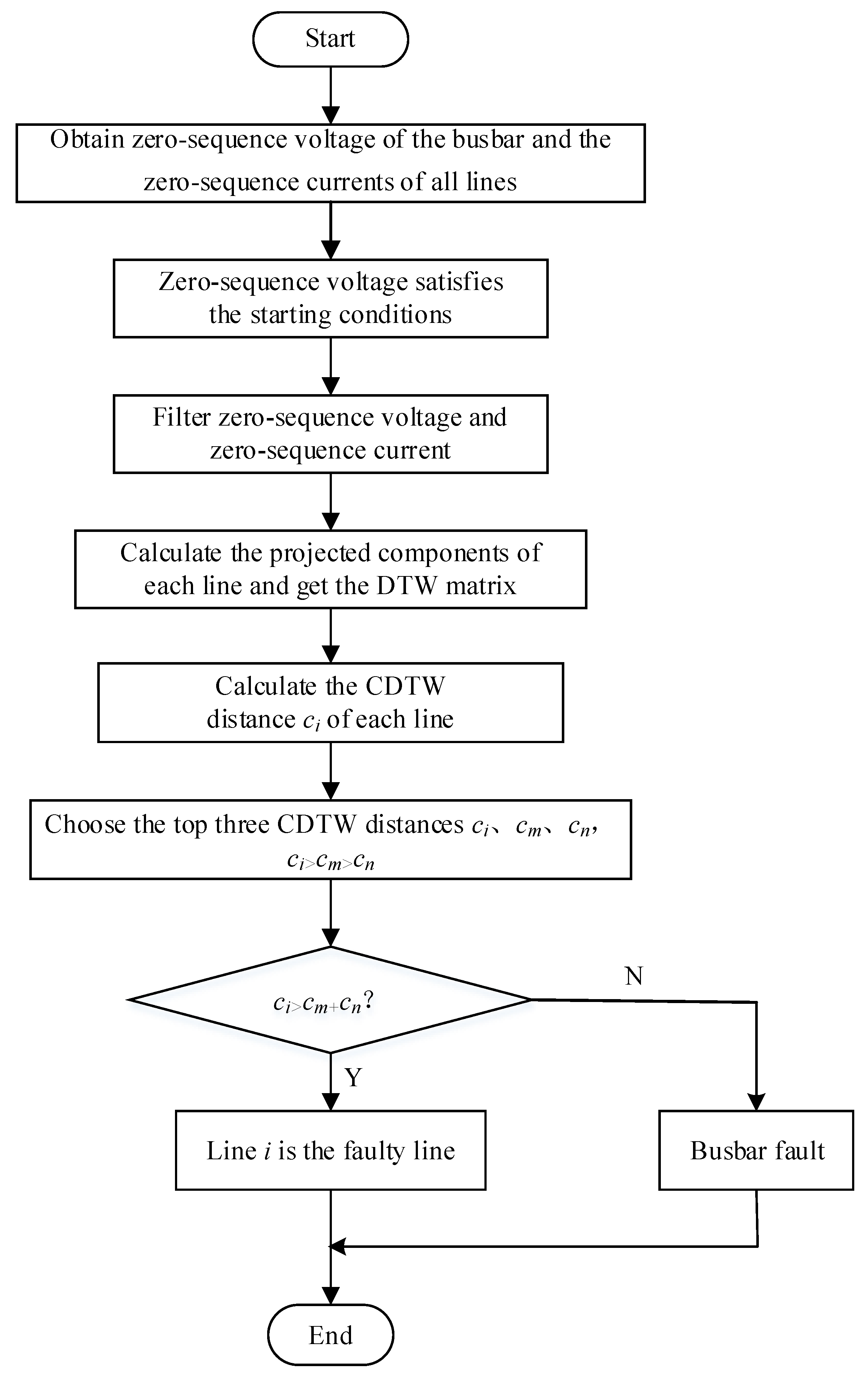
2.2.4. Principle of Faulty Line Selection Method

In this paper, we combine the DTW distance with the comprehensive similarity coefficient to perform the faulty line selection process, and the corresponding criterion is as follows:
When a single-phase grounding fault occurs on line i in the flexible grounding system, the comprehensive similarity coefficient ci of line i is the largest one, which is so much larger than other lines in order to be used to determine the faulty line.
The top three CDTW distances ci, cm, and cn are selected to form the criterion for faulty line selection, c i > c m >   c n . If the condition of c i > c m + c n is met, line i is selected as the faulty line; otherwise, the busbar fault is determined.
The flow chart of faulty line selection in the flexible grounding system based on the CDTW distance is shown in Figure 5. The specific steps are as follows:
(1)
When the monitored instantaneous value of the zero-sequence voltage of the busbar is greater than the threshold KuUn (Un is the rated voltage of the busbar, and the coefficient Ku is usually set to be 0.35 [21]), the faulty line selection process is started.
(2)
The zero-sequence voltage of the busbar and the zero-sequence current of each line are extracted, so the interference of the steady-state component and the unbalanced component is eliminated.
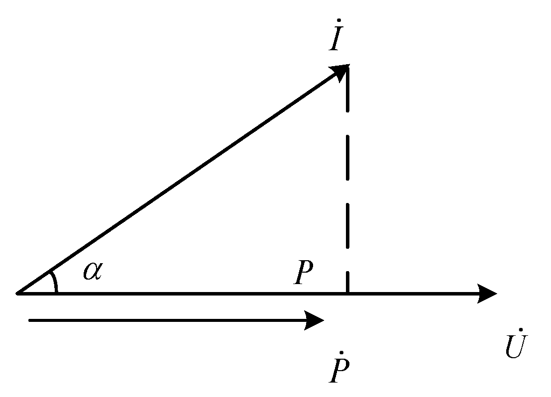
(3)
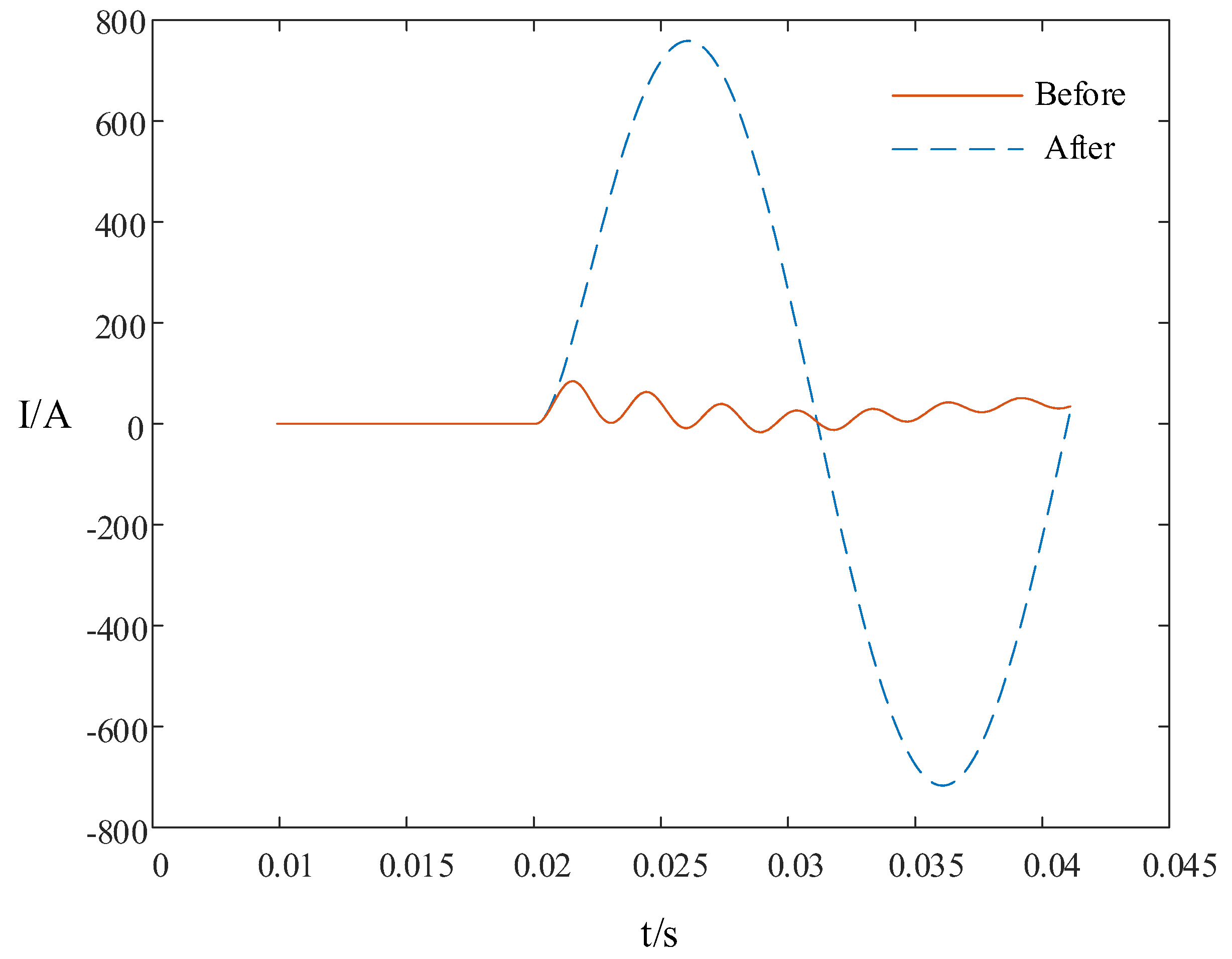
The transient zero-sequence current of the line is projected to the transient zero-sequence voltage of the busbar, and the projection component is calculated by Equation (9).
(4)
The top three CDTW distances ci, cm, and cn are selected to form the criterion for faulty line selection, c i > c m >   c n . If the condition of c i > c m + c n is met, line i is selected as the faulty line; otherwise, the busbar fault is determined.
Figure 5. Flow chart of faulty line selection.
Energies 15 00471 g005

3. Results and Discussion

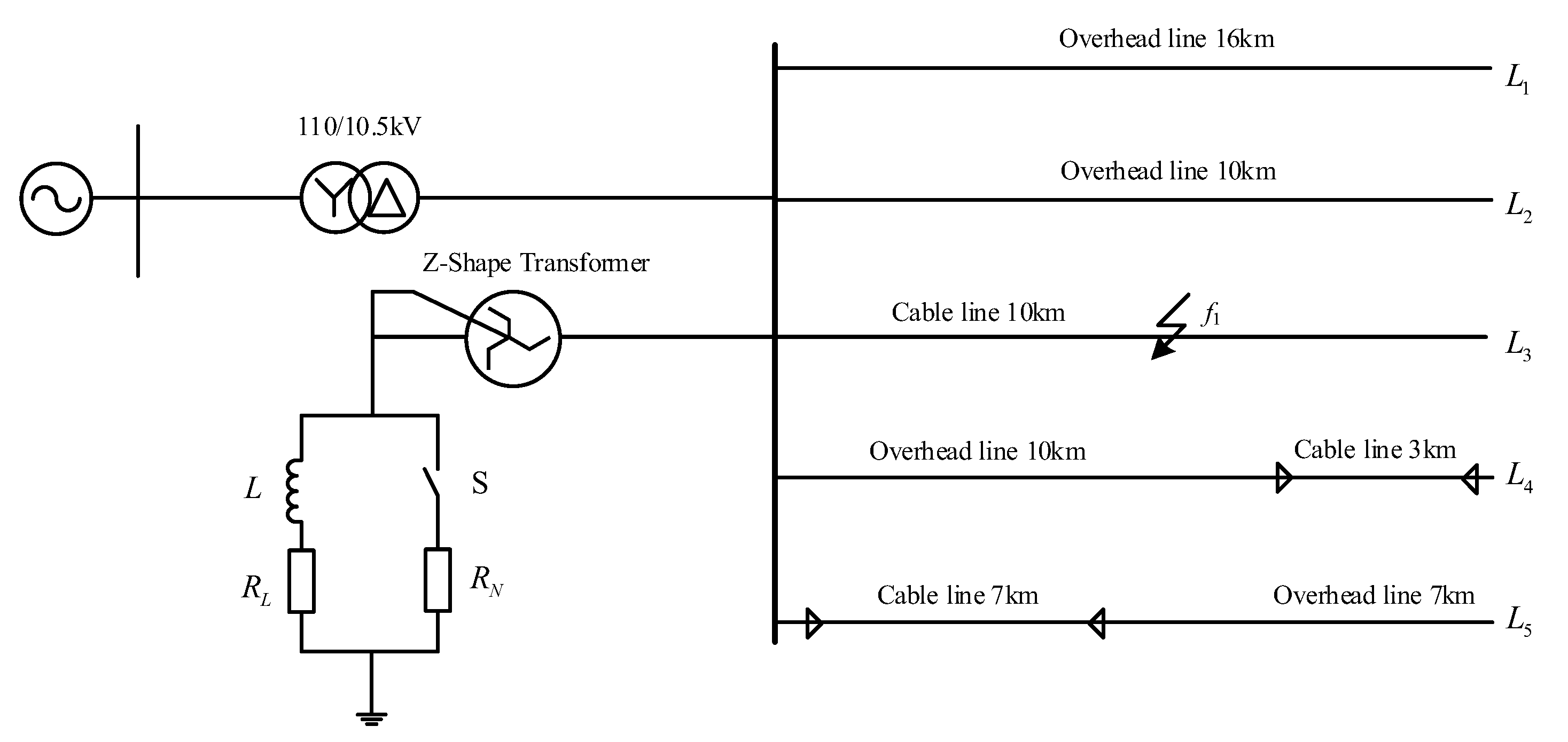
3.1. Simulation Model and Parameters

The 10 kV flexible grounding system model built by MATLAB/Simulink simulation software is shown in Figure 6.
We assume that the system frequency is 50 Hz. The specification of the transformer is the Yd11 transformer, connecting the source and the busbar, and the transformation ratio is 110/10.5 kV. The loads are three-phase balanced, and its active power is unified to 1 MW. The system contains five outgoing lines, of which L3 is a pure cable line, L1 and L2 are pure overhead lines, and the rest are Hybrid cables. The lengths of the lines are L1 = 16 km, L2 = 10 km, L3 = 10 km, L4 = 13 km, and L5 = 14 km, respectively, and the line parameters are shown in Table 1.
Suppose a single-phase grounding fault occurred on line 3 within 0.04 s, and phase A is the faulty phase. The distance between the fault point and the busbar is 5 km.
The arc suppression coil is operating in the over-compensation mode with the degree of −10%, and the parallel resistance of the arc suppression coil is 10 Ω. The calculation formula of the arc suppression coil inductance L of the resonant grounding system is as follows:
L = 1 3 ( 1 + v ) ( 2 π f N ) 2 C 0 l = 1 3 ( 1 + v ) ( 2 π f N ) 2 C
where fN is the power frequency and its value is 50 Hz, C0 is the zero-sequence capacitance of the line, v is the degree of over-compensation, and l is the total length of the line.
In this paper, we suppose the compensation degree of the arc suppression coil is −10%; therefore, the inductance is
L = 1 3 ( 1 + v ) ( 2 π f N ) 2 C = 0.643   H
The resistive active power loss of the arc suppression coil is about 2.5~5.0% of the inductive reactive power loss, and we take 3% in this paper. Therefore, the calculation result of RL is R L = 0.03 ω L = 6.057   Ω .

3.2. Fault Simulation Analysis under Diverse Conditions

In order to verify that the method proposed in this paper is effective for diverse fault conditions in the flexible grounding system, we change the transition resistance, the inception phase angle of the fault and the distance between the fault point and the busbar, respectively, to perform the process of faulty line selection. The effectiveness of the CDTW distance method has been verified by a large number of simulation results.
Connecting a small resistance parallel to the arc suppression coil can effectively increase the zero-sequence current amplitude of the faulty line and make the fault characteristics more obvious. The comparison diagram of the zero-sequence current of the faulty line before and after switching on the small resistance is shown in Figure 7.

3.2.1. Line Selection Results under Different Transition Resistance

To evaluate whether the proposed method can select the faulty line under different transition resistance or not, we assume that a single-phase grounding fault occurred on line 3 at a distance of 5 km from the busbar in the flexible grounding system, and the inception phase angle of the fault is 0 degrees. The results of faulty line selection are shown in Table 2.
By analyzing Table 2, it can be seen that line 3 is judged as the faulty line according to the calculation results of the selection criterion, c i > c m + c n . As the transition resistance increases, the transient signal is significantly weakened, and the CDTW distance is also significantly reduced. However, when the transition resistance goes up to 5000 Ω, the CDTW distance of the faulty line is still much larger than the sum of the top two non-faulty lines with the largest CDTW distance—0.008 > 4.5 × 10⁻⁴. Therefore, we can come to the conclusion that the proposed method is not affected by the value of transition resistance, and the sensitivity of the line selection criterion after the small resistance is switched on is obviously higher than that of the line selection criterion before the small resistance switched on.

3.2.2. Line Selection Results under Different Fault Inception Angle

Assume that a single-phase grounding fault occurred on line 2 at a distance of 5 km from the busbar in the flexible grounding system, and the transition resistance is 10 Ω. The results of faulty line selection are shown in Table 3.
It can be seen from Table 3 that line 2 is selected as the faulty line according to the calculation results of the selection criterion. As the inception phase angle of the fault gradually increases from 0° to 90°, the CDTW distance will increase significantly. When the fault inception phase angle is equal to 0° (too small), the zero-sequence current is still met with the criterion, c i > c m + c n , which is 265.4 > 7.0. Table 3 is also shown that the proposed method is not affected by the value of fault inception phase angle, and the sensitivity of faulty line selection is higher when the small resistance is switched on.

3.2.3. Line Selection Results under Different Fault Distance

Assume that a single-phase grounding fault occurred on line 4 at a different fault distance in the flexible grounding system; the fault inception phase angle of the fault is 45°, and the transition resistance is 100 Ω. The results of faulty line selection are shown in Table 4.
From Table 4, it can be seen that line 4 is judged as the faulty line based on the selection criterion, c i > c m + c n . It is worth noting that the fault location has an impact on the transient signal, but the line selection criterion is still effective. For example, when the fault location is 12 km away from the busbar, the selection criterion is also met. Table 4 also shows that the proposed method is not affected by the fault location, and the sensitivity of faulty line selection is higher when the small resistance is switched on.
From the above analysis, we can come to the conclusion that the line selection result is not affected by the different transition resistance, inception phase angle of the fault, and fault location, and the effectiveness of the method based on CDTW distance is verified.

3.2.4. Line Selection Results in Case of Busbar Failure

Assume that a single-phase grounding fault occurred on the busbar in the flexible grounding system, and the different fault conditions and the corresponding simulation results after the small resistance is switched on are shown in Table 5.
It can be seen from Table 5 that busbar failure is determined if the selection criterion is not met, i.e., c i < c m + c n . Additionally, the effectiveness of the proposed selection method is not affected by changing the transition resistance or the inception phase angle of the fault.

3.2.5. Line Selection Results Considering the Access of Renewable Energy Sources

At present, a large number of renewable energy power sources are connected to the distribution network, and it is necessary to discuss its influence on the proposed method of faulty line selection [22,23].
Assume that a single-phase grounding fault occurred on line 3 in the flexible grounding system with the renewable energy power sources is connected, and the different fault conditions and its corresponding simulation results after the small resistance is switched on are shown in Table 6.
From the simulation results considering the access of renewable energy sources in Table 6, line 3 is judged as the faulty line based on the selection criterion, c i > c m + c n . Additionally, the effectiveness of the proposed selection method is not affected by different transition resistances or the inception phase angle of the fault.

3.2.6. Line Selection Results Compared with Other Methods

Assume that a single-phase grounding fault occurred on line 2 in the flexible grounding system, the transition resistance is 500 Ω, the initial phase angle of the fault is 0°, and the fault point is 5 km away from the busbar. We select three verified faulty line selection methods to compare with the method proposed in this paper. The comparison simulation results are shown in Table 7.
From the simulation results in Table 7, methods based on Wavelet packet energy, Grey relational degree, and Fifth harmonic all judged the wrong faulty line selection result under certain extreme fault conditions. Conversely, using the proposed method, the CDTW distance of L2 is up to 0.87, which is much larger than that of other lines, and the line selection result is correct. Therefore, compared with the three methods above, it can be seen that the proposed method in this paper is more reliable.

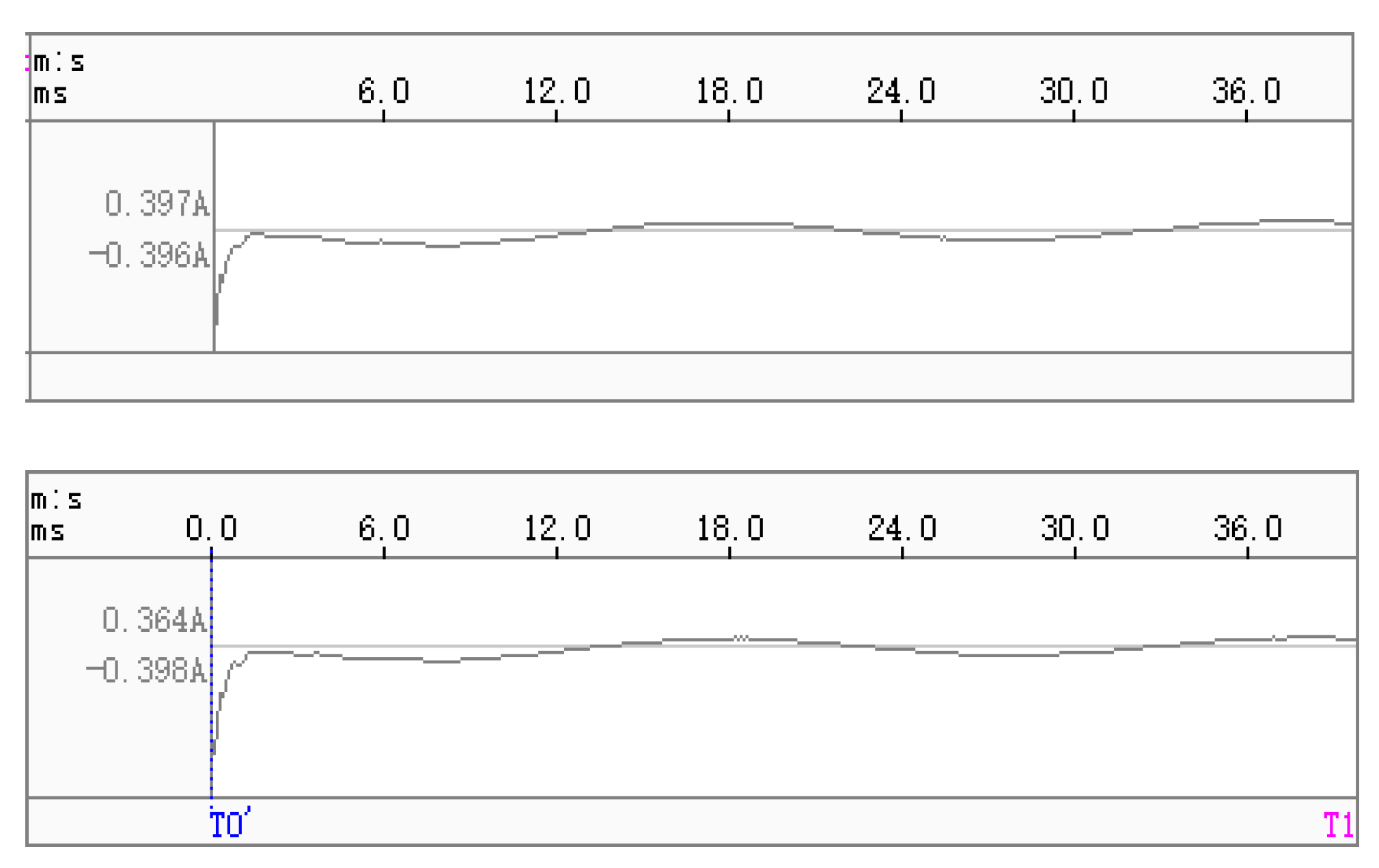
3.3. Field Data Test and Analysis

In order to verify the effectiveness of the proposed method, the field data are collected to perform the process of faulty line selection. The fault record of zero-sequence voltage and current is shown in Figure 8. First, field data of the zero-sequence voltage of the busbar and the zero-sequence current of three lines are collected. Then the DTW distance among the three lines is calculated respectively, and finally, the CDTW distance of each line is obtained to determine the faulty line.
The DTW distance matrix of three on site lines is obtained according to the field data as follows:
M = [ 0 4.0573 × 10 7 4.0492 × 10 7 4.0573 × 10 7 0 239.8920 4.0492 × 10 7 239.8920 0 ]
The CDTW distance of each line is calculated by Equation (7), and the result of the field data test is shown in Table 8.
From Table 8, it can be seen that the CDTW distance of Line Zhuolan A is much larger than the sum of the CDTW distances of Line Zhuolan B and Line Zhuojin B, which is consistent with the actual failure situation. Therefore, the proposed method is also effective for the field data test.

4. Conclusions

When a single-phase grounding fault occurs in a flexible grounding system, the amplitude and polarity of the transient zero-sequence current in the faulty line and the non-faulty line are quite different. The transient zero-sequence current of the line is projected on the transient zero-sequence voltage of the busbar in this paper to characterize the difference between the faulty line and the non-faulty line. Combined with the DTW distance and the waveform comprehensive similarity coefficient, the CDTW distance of each line is obtained and compared to select the faulty line. A conclusion can be obtained on the basis of a large number of simulation experiments and field data tests.
(1)
Projecting the transient zero-sequence current of the line on the transient zero-sequence voltage of the busbar by the transient projection method can distinguish the difference between the faulty line and non-faulty line more clearly, which would improve the accuracy of single-phase grounding line selection in the flexible grounding system.
(2)
The faulty line selection method proposed in this paper can accurately select the faulty line in spite of different transition resistances, fault inception phase angles, and fault point locations.
(3)
A large amount of simulation data shows that the method proposed in this paper has strong adaptability to the occurrence of a high-resistance fault in flexible grounding systems, and the ability to detect transition resistance is up to 5000 Ω.
(4)
The field data test also shows the effectiveness of the faulty line selection method based on the CDTW distance proposed in this paper.
(5)
The simulation results show that the proposed method is also effective in distribution networks with renewable energy sources connected.
(6)
Compared with the methods based on, Wavelet packet energy, Grey relational degree, and Fifth harmonic, the proposed method in this paper is more reliable.
The CDTW method proposed in this paper is effective in selecting the faulty line under diverse fault conditions and is not affected by the impact of accessing renewable energy sources. As the similarity of the zero-sequence current between upstream and downstream of the fault point can also be used to locate the fault point, we considered using the CDTW distance to locate the fault section in flexible grounding systems.

Author Contributions

Conceptualization, Y.H. and X.Z.; software, W.W.; validation, A.G.; writing—original draft preparation, J.Z.; writing—review and editing, W.B.; visualization, Y.C. All authors have read and agreed to the published version of the manuscript.

Funding

This research was funded by the National Key Research and Development Program of China (2017YFC0907004) and the University & Zibo City Integration Development Project (2022ZDXC001).

Data Availability Statement

Not applicable.

Acknowledgments

The authors are very grateful to the anonymous referees for their helpful comments and constructive suggestions.

Conflicts of Interest

The authors declare no conflict of interest.

Nomenclature

DTWDynamic Time Warping
Rftransition resistance at the fault point (ohm)
Linductance of the arc suppression coil (H)
Cizero-sequence distributed capacitance of the non-faulty line (F)
Cnzero-sequence distributed capacitance of the faulty line (F)
L0equivalent inductance of the arc suppression coil (H)
R0equivalent zero-sequence resistance of the transition resistance (ohm)
UC0zero-sequence voltage of the busbar (V)
U0zero-sequence equivalent voltage at the fault point (V)
If(0)zero-sequence current of the faulty line (I)
cicomprehensive similarity coefficient
vdegree of over-compensation
fNpower frequency (Hz)
RLresistive active power loss of the arc suppression coil (ohm)

References

  1. Tang, Y.; Chang, Y.; Tang, J.; Xu, B.; Ye, M.; Yang, H. A Novel Faulty Phase Selection Method for Single-Phase-to-Ground Fault in Distribution System Based on Transient Current Similarity Measurement. Energies 2021, 14, 4695. [Google Scholar] [CrossRef]
  2. Shao, W.; Bai, J.; Cheng, Y.; Zhang, Z.; Li, N. Research on a Faulty Line Selection Method Based on the Zero-Sequence Disturbance Power of Resonant Grounded Distribution Networks. Energies 2019, 12, 846. [Google Scholar] [CrossRef] [Green Version]
  3. Yu, K.; Liu, Z.; Zeng, X.; Li, J.; Yang, L. A novel full compensation method for the ground fault current of resonant grounded systems. Electr. Eng. 2021, 103, 1569–1581. [Google Scholar] [CrossRef]
  4. Ye, S.; Ma, Z.; Hu, X.; Jin, N.; Shen, Z.; Wan, Y.; Zhou, H. Study on Security and Reliability of Distribution Network Neutral Grounding Mode Through Arc Suppression Coil and Line-selecting Resistance in Parallel. Energy Eng. 2011, 18–22. [Google Scholar] [CrossRef]
  5. Yi, M.; Yan, T.; Zhou, Z.; Peng, J. Experimental study on single phase grounding fault of a neutral grounding device consisted of an arc suppression coil and a parallel controllable switching low resistance. Hubei Electr. Power 2017, 41, 20–23. [Google Scholar]
  6. Veerasamy, V.; Wahab, N.I.A.; Ramachandran, R.; Mansoor, M.; Thirumeni, M.; Othman, M.L. High Impedance Fault Detection in Medium Voltage Distribution Network Using Discrete Wavelet Transform and Adaptive Neuro-Fuzzy Inference System. Energies 2018, 11, 3330. [Google Scholar] [CrossRef] [Green Version]
  7. Wang, X.; Zhang, H.; Shi, F.; Wu, Q.; Terzija, V.; Xie, W.; Fang, C. Location of single phase to ground faults in distribution networks based on synchronous transients energy analysis. IEEE Trans. Smart Grid 2020, 11, 774–785. [Google Scholar] [CrossRef] [Green Version]
  8. Li, J.; Li, Y.; Wang, W.; Song, J.; Zhang, Y. Fault Line Detection Method for Flexible Grounding System Based on the Change of Phase Difference between Zero Sequence Current and Voltage. Power Syst. Technol. 2021, 45, 4847–4855. [Google Scholar]
  9. Xu, Q.; Xu, Y.; Zhou, D.; Xi, X. Single-phase high-resistance grounding analysis of low-resistance grounded distribution network line protection. Power Syst. Autom. 2010, 34, 91–94, 115. (In Chinese) [Google Scholar]
  10. Yang, F.; Jin, X.; Shen, Y.; Lei, Y.; Xue, Y.; Xu, B. Ground fault direction discrimination algorithm for flexible grounding system based on zero sequence admittance change. Power Syst. Autom. 2020, 44, 88–97. (In Chinese) [Google Scholar]
  11. Xue, Y.; Liu, S.; Wang, Y.; Xu, B. Groundingfault protection in low resistance grounding system based on zerosequencevoltage ratio restrain. Autom. Electr. Power Syst. 2016, 40, 112–117. (In Chinese) [Google Scholar]
  12. Sheng, Y.; Cong, W.; Bu, X.; Li, X. Detectionmethod of high impedance grounding fault based on differentialcurrent of zero-sequence current projection and neutral pointcurrent in low-resistance grounding system. Electr. Power Autom. Equip. 2019, 39, 17–22. (In Chinese) [Google Scholar]
  13. Alhelou, H.H.; Golshan, M.E.H.; Hatziargyriou, N.D. Deterministic Dynamic State Estimation-Based Optimal LFC for Interconnected Power Systems Using Unknown Input Observer. IEEE Trans. Smart Grid 2019, 11, 1582–1592. [Google Scholar] [CrossRef]
  14. Alhelou, H.H.; Golshan, M.H.; Askari-Marnani, J. Robust sensor fault detection and isolation scheme for interconnected smart power systems in presence of RER and EVs using unknown input observer. Int. J. Electr. Power Energy Syst. 2018, 99, 682–694. [Google Scholar] [CrossRef]
  15. Alhelou, H.H.; Golshan, M.E.H.; Hatziargyriou, N.D. A Decentralized Functional Observer based Optimal LFC Considering Unknown Inputs, Uncertainties and Cyber-Attacks. IEEE Trans. Power Syst. 2019, 34, 4408–4417. [Google Scholar] [CrossRef]
  16. Zhuang, S.; Miu, X.; Jiang, Y.; Guo, M. A Line Selection Method for Single-phase High-impedance Grounding Fault in Resonant Grounding System of Distribution Network Based on Improved Euclidean-dynamic Time Warping Distance. Power Syst. Technol. 2020, 44, 273–281. [Google Scholar] [CrossRef]
  17. Huang, C.; Liu, P.; Jiang, Y.; Leng, H.; Zhu, J. Line Differential Protection Based on Dynamic Time Warping Distance in Active Distribution Network. Trans. China Electrotech. Soc. 2017, 32, 240–247. (In Chinese) [Google Scholar]
  18. Chu, J.; Yuan, X.; Chen, B.; Wang, X.; Qiu, H.; Gu, W. A Method for Distribution Network Voltage Sag Source Identification Combining Wavelet Analysis and Modified DTW Distance. Power Syst. Technol. 2018, 42, 637–643. [Google Scholar]
  19. Shu, H.; Zhu, M.; Huang, W.; Duan, R. Faulty line. selection based on time-frequency characteristics of transient zerosequence current. Electr. Power Autom. Equip. 2013, 33, 1–6. (In Chinese) [Google Scholar]
  20. Zhan, Q. Distribution Network High Impedance Fault Resolving Technique Study Based on Transition State Projection Method; Fuzhou University: Fuzhou, China, 2018. [Google Scholar]
  21. Wei, X.; Shu, N. Single-phase grounding fault line selection method of distribution network based on Hausdorff distance. J. Electr. Power Syst. Autom. 2020, 32, 133–142. [Google Scholar]
  22. Haesalhelou, H.; Parthasarathy, H.; Nagpal, N.; Agarwal, V.; Nagpal, H.; Siano, P. Decentralised Stochastic Disturbance Observer-Based Optimal Frequency Control Method for Interconnected Power Systems with High Renewable Shares. IEEE Trans. Ind. Inform. 2021. [Google Scholar] [CrossRef]
  23. Alhelou, H.A.H.; Cuffe, P. A Dynamic State Estimator Based Tolerance Control Method Against Cyberattack and Erroneous Measured Data for Power Systems. IEEE Trans. Ind. Inform. 2021. [Google Scholar] [CrossRef]
Figure 1. Schematic diagram of single-phase grounding fault in flexible grounding system.
Energies 15 00471 g001
Figure 2. Zero-sequence equivalent circuit diagram of single-phase grounding fault in the flexible grounding system.
Energies 15 00471 g002
Figure 3. Illustration of DTW path.
Energies 15 00471 g003
Figure 4. Projection vector diagram of line zero-sequence current on the busbar zero-sequence voltage.
Energies 15 00471 g004
Figure 6. The 10 kV flexible grounding system simulation model.
Energies 15 00471 g006
Figure 7. Comparison diagram of zero-sequence current of the faulty line before and after the small resistance is switched on.
Energies 15 00471 g007
Figure 8. The fault record of zero-sequence voltage and current.
Energies 15 00471 g008aEnergies 15 00471 g008b
Table 1. Line parameters of the flexible grounding simulation model.
Line Parameters R 0 / Ω C 0 / μ F L 0 / mH R 1 / Ω C 1 / μ F L 1 / mH
Overhead line0.27500.00544.60000.12500.00961.3000
Cable line2.70000.28001.01900.27000.39900.2550
Table 2. Line selection results under different transition resistances.
Transition Resistance/ΩCDTW Distance of Line 1–5Selection Criterion
c i > c m + c n
L1L2L3L4L5
0B104.3108.2482.3113.8106.7482.3 > 222.0
A16.216.8973.917.518.3973.85 > 35.72
10B31.132.4150.827.837.5150.8 > 69.9
A5.55.7337.56.06.2337.52 > 12.18
100B1.01.05.20.81.35.2 > 2.3
A0.20.315.30.30.315.27 > 0.53
1000B0.010.010.060.010.010.06 > 0.02
A3.1 × 10−33.2 × 10−30.23.0 × 10−33.2 × 10−30.194 > 6.4 × 10⁻³
3000B1.2 × 10−31.3 × 10−36.3 × 10−39.8 × 10−41.5 × 10−36.3 × 10⁻³ > 2.8 × 10⁻³
A3.5 × 10−43.6 × 10−40.023.7 × 10−43.9 × 10−40.022 > 7.6 × 10⁻⁴
5000B4.4 × 10−44.5 × 10−42.3 × 10−33.6 × 10−45.7 × 10−42.3 × 10⁻³ > 1.0 × 10⁻³
A1.3 × 10−41.8 × 10−40.0082.2 × 10−42.3 × 10−40.008 > 4.5 × 10⁻⁴
B represents the state before the small resistance is switched on, while A represents the state after the small resistance is witched on. Bold indicates the simulation data of the faulty line.
Table 3. Line selection results under different fault inception angles.
Fault Inception Phase Angle/RadCDTW Distance of Line 1–5Selection Criterion
c i > c m + c n
L1L2L3L4L5
0B66.0508.364.428.725.4508.3 > 130.4
A3.9265.43.11.31.3265.4 > 7.0
π 6 B958.26898.2881.3390.8366.16898.2 > 1839.5
A80.73244.557.526.226.73244.5 > 138.2
π 4 B1549.618,925.01350.6564.7565.318,925.0 > 2900.2
A146.26513.3103.745.648.06513.3 > 249.9
π 3 B1159.311,190.5978.6400.6423.411,190.5 > 2137.9
A154.36141.3105.039.948.86141.3 > 259.3
π 2 B156.52586.4165.176.270.92586.4 > 321.6
A14.81683.814.46.06.51683.8 > 29.2
B represents the state before the small resistance is switched on, while A represents the state after the small resistance is witched on. Bold indicates the simulation data of the faulty line.
Table 4. Line selection results under different fault distance.
Fault Distance/KmCDTW Distance of Line 1–5Selection Criterion
c i > c m + c n
L1L2L3L4L5
1B84.086.6125.8457.360.5457.3 > 212.4
A22.423.133.8614.515.2265.4 > 7.0
5B138.1142.0208.8649.785.9649.7 > 350.8
A32.333.249.2782.623.0782.6 > 82.4
7B123.6127.1185.4657.988.6657.9 > 312.5
A26.932.640.7684.119.2684.1 > 73.3
10B124.4128.1187.6585.588.9585.5 > 315.7
A23.223.935.3602.816.6602.8 > 59.2
12B100.1103.1150.3520.071.6520.0 > 253.4
A18.919.428.6521.713.5521.7 > 48.0
B represents the state before the small resistance is switched on, while A represents the state after the small resistance is witched on. Bold indicates the simulation data of the faulty line.
Table 5. CDTW distance after the small resistance is switched on in the case of busbar failure.
Fault Inception Phase Angle/RadTransition Resistance /ΩCDTW Distance of Line 1–5Selection Criterion
c i < c m + c n
Line Selection Result
L1L2L3L4L5
0055.557.270.460.744.770.4 < 117.9Busbar
π 6 10262.5271.3330.4204.3171.8330.4 < 533.8Busbar
π 3 10012.112.518.67.88.518.6 < 24.6Busbar
π 2 5000.0330.0330.0640.0340.0330.064 < 0.067Busbar
Table 6. CDTW distance considering the access of renewable energy sources.
Fault Inception Phase Angle/RadTransition Resistance /ΩCDTW Distance of Line 1–5Selection Criterion
c i > c m + c n
Line Selection Result
L1L2L3L4L5
0017.818.4961.724.023.1961.7 > 47.1L3
π 6 1017.117.7913.219.523.9913.2 > 43.4L3
π 4 505.35.5279.25.37.9279.2 > 13.4L3
π 3 1002.72.8145.82.04.2145.8 > 7.0L3
π 2 5000.20.212.30.20.412.3 > 0.6L3
Bold indicates the simulation data of the faulty line.
Table 7. Simulation results using different faulty line selection methods.
Faulty Line Selection MethodFault CriterionFeeder NumberJudgement Result
12345
CDTW distancethe value of CDTW distance0.020.870.020.010.01L2
Wavelet packet energyrelative energy0.060.520.460.920.55L4
Grey relational degreethe degree of gray correlation of each feeder2.372.522.913.112.32L5
Fifth harmonicthe magnitude of fifth harmonic component0.060.620.771.810.49L4
Bold indicates the simulation data of the faulty line.
Table 8. CDTW distance of the field data test.
CDTW Distance of Each LineSelection Criterion
c i > c m + c n
Line Selection Result
Line Zhuolan ALine Zhuolan BLine Zhuojin B
2.0 × 10760.060.02.0 × 107 > 120.0Line Zhuolan A
Publisher’s Note: MDPI stays neutral with regard to jurisdictional claims in published maps and institutional affiliations.

