Review

A Survey of Islanding Detection Methods for Microgrids and Assessment of Non-Detection Zones in Comparison with Grid Codes

by
José Antonio Cebollero
1,
David Cañete
1,
Susana Martín-Arroyo
1,
Miguel García-Gracia
1,* and
Helder Leite
2
1
Electrical Engineering Department, University of Zaragoza, 50018 Zaragoza, Spain
2
Faculty of Engineering (FEUP), University of Porto, 4200-465 Porto, Portugal
*
Author to whom correspondence should be addressed.
Energies 2022, 15(2), 460; https://doi.org/10.3390/en15020460
Submission received: 9 November 2021 / Revised: 14 December 2021 / Accepted: 5 January 2022 / Published: 10 January 2022

Abstract

:
Detection of unintentional islanding is critical in microgrids in order to guarantee personal safety and avoid equipment damage. Most islanding detection techniques are based on monitoring and detecting abnormalities in magnitudes such as frequency, voltage, current and power. However, in normal operation, the utility grid has fluctuations in voltage and frequency, and grid codes establish that local generators must remain connected if deviations from the nominal values do not exceed the defined thresholds and ramps. This means that islanding detection methods could not detect islanding if there are fluctuations that do not exceed the grid code requirements, known as the non-detection zone (NDZ). A survey on the benefits of islanding detection techniques is provided, showing the advantages and disadvantages of each one. NDZs size of the most common passive islanding detection methods are calculated and obtained by simulation and compared with the limits obtained by ENTSO-E and islanding standards in the function of grid codes requirements in order to compare the effectiveness of different techniques and the suitability of each one.

1. Introduction

Distributed generation resources have become an attractive option to locally generate energy in small scale microgrids. Most microgrids can work both in grid-connected mode and in islanded mode, and the change from grid-connected mode to islanded mode can take place in two ways: intentionally and unintentionally. The first case is applied locally in the microgrid for maintenance such as live working or economic purposes, and it does not pose any issue as the plant controller is aware of the situation. However, unintentional islanding is problematic because it is performed by an external agent and the microgrid plant controller is not aware of this issue. Then, if the local generators continue injecting power, the utility grid will continue to be electrified. This situation entails safety issues because maintenance workers can be at risk of electrocution if they manipulate the utility grid when it is supposed to be unelectrified. Consequently, a reliable islanding detection system is very important in every distributed power plant. In addition, unintentional islanding can affect local stability and the devices of the microgrid. Reconnection from undetected unintentional islanding can cause inverters and synchronous generators to be out of voltage, frequency and synchronism, being at risk of damage when reconnection occurs. Interconnection codes establish that distributed power plants must incorporate islanding detection and the necessary circuits and actuators to disconnect the generation systems in a limited period of time after an unintentional islanding occurs [1]. These methods can be compatible with all earthing systems, and they are independent of other grid protections.
A wide range of works regarding unintentional islanding detection in distributed generation microgrids can be found in the literature. Reference [2] classifies and evaluates the most relevant methods in three categories, whereas [3,4] give a more technical overview of some passive and active methods, respectively. References [5,6] also classify and describe the most relevant methods. Paper [7] includes a catalogue of islanding methods and a research regarding their behavior according to the principle of detection, i.e., the physical magnitude that is monitored (frequency, harmonics, impedance, power variation, etc.). Reference [8] is another survey about islanding detection in microgrids which also includes the classification of techniques and a description of the most relevant methods. In paper [9], a review of islanding detection methods is shown, and a new technique is presented.
Reference [10] contains, apart from a list of methods, the islanding regulations of IEC, IEEE, UL, Germany, Spain and Italy, as well as a study about the influence of islanding in microgrids, proposing a communication method based on a hierarchical scheme. The work of [11] contains a theory about the implementation of islanding detection methods at the microswitch and not at individual microsources in multi-inverter systems, proposing a conceptual test circuit in consonance with the IEEE 1547 standard [1]. In reference [12], after a brief explanation of some well-known methods, a study of the analytical basis to understand the influence of the load and the type of DG during islanding is presented. Reference [13] includes a study of some aspects of the architecture, grid code compatibility and significant issues of some islanding detection methods. Reference [14] analyzes the behavior and the detection time of three basic islanding detection techniques using MATLAB-Simulink simulations. Reference [15] focuses on islanding detection methods based on grid synchronization and PLLs, as well as the subsequent reconnection after an islanding event. Reference [16] contains a quick review of islanding detection methods that focuses on those based on signal measurement and mathematical treatment, such as Fourier transform or wavelet transform.
Many islanding detection methods are classic and well-known, whereas some others are more specific and less relevant. To establish a classification that comprises most of them is not an easy task because of their different bases, specifications and scopes. An important issue is the location where they reside, which allows to differentiate between local methods and remote methods. Local methods are those that are fully included in the microgrid. In small power plants, the power plant controller can be the PV inverter, so many methods are derived from this device. Larger power plants can have a specific power plant controller that manages all power sources of the microgrid. In this case, a local detection method should be included in the power plant controller. A relevant characteristic of local methods is that islanding detection is carried out by measuring local parameters and signals of the microgrid, with or without the introduction of any type of disturbance. Then, local methods can be classified into three categories: passive methods, active methods and hybrid methods. Passive methods consist of measuring some magnitudes of the microgrid (such as voltage, current, frequency, phase, power, etc.) to analyze parameters as its value, its rate of change or its harmonic content. Active methods are those that deliberately introduce disturbances to the microgrid to analyze their effects, for example, deviations in voltage, current or frequency. A third category called hybrid methods can be established to include methods that use more than one technique simultaneously.
On the other hand, remote methods are those that are fully or partially resident in the utility grid. Some of them consist of active data communication from the utility grid to the distributed generators, which are classified as communication methods. Another group of remote methods are those that are based on the addition of a component on the grid side, for example, an impedance that is connected or changes its value in case of islanding. These have been included in a category called utility grid methods.
In practice, it is quite usual to implement an islanding detection procedure in distributed power plants that combines several of these methods, especially a simple one such as Over Under Voltage or Over Under Frequency, with some more advanced and more effective than others. In the same way, it is difficult to determine a method as the best choice for a specific power plant or microgrid because there are particular characteristics that make each of the choices more or less suitable. The performance and the cost are relevant factors in the anti-islanding method selection, being important to achieve a good compromise between them. Stability and power quality are also important issues in distributed power plants [17]; therefore, islanding detection methods should not compromise them. Harmonic disturbance is one of the main factors to consider [18], being especially relevant to the interaction between PV inverters and grid components [19]. Even passive methods can cause power quality issues in renewable distributed energy power plants [20]. Consequently, complex controllers are often required in distributed generation systems to guarantee stability under a wide range of circumstances [21].
In this work, a complete survey of islanding detection methods has been elaborated. It is important to note that in the literature, many different lists can be found because some techniques have similarities and can be considered a variation of an existing method by some authors or as a new method for other authors. Figure 1 show the proposed classification of the islanding methods that are described in this paper, and in Table 1, Table 2, Table 3, Table 4 and Table 5, the most relevant information of each method is shown.
Table 1. Resume of the passive islanding methods presented in this document.
Passive MethodsDetection TimeEffectivenessError Detection RateNDZMultiple invertersPower Quality Degradation
Over Under Voltage and Over Under Frequency [2]4 ms–2 sLow if there is a small mismatch between local generation and local consumptionLowLargeYesNo
Rate of Change of Output Power
[16,22,23,24,25]
24–26 msLow if balanced loads or if local generators cannot compensate the load changeHighSmallYesNo
Rate of Change of Voltage/Frequency/Frequency over Output Power [9,15,26,27,28,29,30]24 ms (V)
24 ms (F)
100 ms (FoOP)
Good unless the capacity of the generation units matches the demanded loadHighSmallYesNo
Voltage Unbalance [31]53 msGoodLowLargeYesNo
Voltage Phase Jump Detection [2,6,21,32,33,34,35,36,37,38,39]10–20 msGood unless power factor closes to unityLowLargeYesNo
Harmonic Content of Voltage and Current [31,40,41,42,43,44,45,46]45 msGood, but it can fail with high Q, and if RLC loads attenuate the measured frequencyHighLarge for High QYesNo
Wavelet Transform [9,16,47,48,49,50,51]<20 msOnly effective if all generation units are connected to the PCC via DC-AC inverters-Very smallYesNo
Fourier and other Mathematical Transform-Based Methods [52,53,54,55,56,57,58]<1 ms (F)
26 ms (S)
Efficient, but high computational cost--YesNo
Table 2. Resume of the active islanding methods presented in this document.
Active Methods [59]Detection TimeEffectivenessError Detection RateNDZMultiple InvertersPower Quality Degradation
Change of Impedance [60,61]10 msOnly good with small generation unitsLowSmallYes (complexity increases)No
Active Impedance Detection [62,63,64,65,66,67,68]0.77–0.95 msGood if the utility grid is strongLowSmallNoYes
Harmonic Component Injection [16,69,70,71,72,73,74,75,76]Few msGood if the utility grid is strongLowVery smallYes, but one inverter has to be the master oneYes (slightly)
PLL Phase Perturbation [77,78]120 msGood if the utility grid is strongLowSmallYesYes (negligible)
Slip Mode Frequency Shift [36,79,80,81,82]0.4 msIt can fail if the load phase slope is greater than the frequency deviation slopeLowSmallYesYes
Active Frequency Drift [2,15,83]2 sVery effective for pure resistance loads, it may fail for other types of loadsHighLarge for high QYesYes
Sandia Frequency Shift [84,85,86,87,88,89]0.5–1 sGood when the generation units are connected via constant current-controlled inverters, bad when the generation units are connected via constant power-controlled invertersLower than Active Frequency DriftSmaller than Active Frequency DriftYesYes (slightly)
Sandia Voltage Shift [90]0.5 sThe most efficient method based on positive feedbackLowSmallYes, but performance reduces and detection time is longerYes (slightly)
Frequency Jump [2]75 msIf multiple inverters are not synchronized, the variations introduced by each one could act to cancel each other out, resulting in detection failureLowSmallYes, but it loses effectiveness unless the dithering of the frequency is synchronizedYes
Variation of Active Power/Reactive Power [91,92,93]0.3 s (A)
2 s (R)
Instability problems may appear because the generation units continuously inject extra active/reactive power to the gridLowSmallYes, but a cross-correlation index of the rate of change has to be introducedYes
Reactive Power Export Error Detection [94]2 sIt can detect the islanding fault even when there is no load change in the microgridLowSmallNo, they tend to maintain a unit power factorYes
Reactive Power versus Frequency (Q-f) Droop [95]190 msIt forces the synchronous generators to lose their stable operation, relying on OUF detectionLowVery smallYesYes
Sudden Change in Impedance [2]-In the case of desynchronization, NDZ becomes higher if the number of inverters increasesLowSmall Yes, but injections could interfere and cause false trips if not using de-synchronized invertersYes
Virtual Capacitor/
Virtual Inductor/
Virtual Resistor [96,97,98]
20–51 ms (C)
13–59 ms (L)
39 ms (R)
Effective under different types of loadsLowSmall-Yes
Table 3. Resume of the hybrid islanding methods presented in this document.
Hybrid MethodsDetection TimeEffectivenessError Detection RateNDZMultiple InvertersPower Quality Degradation
Voltage Unbalance and Sandia Frequency Shift [99]0.15–0.21 sSame as Sandia Frequency ShiftSame as Sandia Frequency ShiftSame as Sandia Frequency ShiftYesTemporary (only when Sandia Frequency Shift triggered)
Rate of Change of Voltage and Variation of Active/Reactive Power [100,101]0.5 sSame as Variation of Active PowerSame as Variation of Active PowerSame as Variation of Active PowerYesTemporary (only when Variation of Active/Reactive Power triggered)
Rate of Change of Voltage/Frequency and High-Frequency Voltage Perturbation [102]0.2 sSame as a High-Frequency Voltage PerturbationSame as a High-Frequency Voltage PerturbationSame as a High-Frequency Voltage Perturbation-Temporary (only when High-Frequency Voltage Perturbation triggered)
Rate of Change of Reactive Power and Load Connecting Strategy [103]40 msSame as Load Connecting StrategyLoad Connecting StrategySmall (Load Connecting Strategy)YesTemporary (only when Load Connecting Strategy triggered)
Sandia Frequency Shift and Reactive Power versus Frequency Droop [104]1.4 sHigher than standard Sandia Frequency ShiftLower than standard Sandia Frequency ShiftLower than standard Sandia Frequency Shift-Yes (lower than standard Sandia Frequency Shift)
Table 4. Resume of the communication islanding methods presented in this document.
Communication Methods [105,106]Detection TimeEffectivenessError Detection RateNDZMultiple InvertersPower Quality Degradation
Power Line Carrier Communication [107,108,109]Very few msVery highNoneNoYesNo
Standard Data Communication [110,111]Very few msVery highNoneNoYesNo
Table 5. Resume of the utility islanding methods presented in this document.
Utility MethodsDetection TimeEffectivenessError Detection RateNDZMultiple InvertersPower Quality Degradation
Impedance Insertion [46]Few msVery highLow but possible if impedance sizes out the minimum variation of phaseVery smallYesNo
Furthermore, according to each normal operating range defined by standards and national regulations, a particular NDZ is obtained for each anti-islanding protection method. In this work, the novelty is the NDZ evaluation for ENTSO-E and standards and the comparison of these limits with the NDZs obtained by calculation and simulation for the most common passive islanding detection methods.
The remainder of this paper is organized as follows. Section 2 and Section 3 show local and remote islanding detection methods, respectively. Section 4 presents the comparison of NDZs considering grid codes, islanding standards and common islanding detection methods. A review of future trends is shown in Section 5, and finally, the conclusions of this work are presented in Section 6. Appendix A contains a list of the abbreviations and acronyms used in this manuscript.

2. Overview of Local Detection Methods

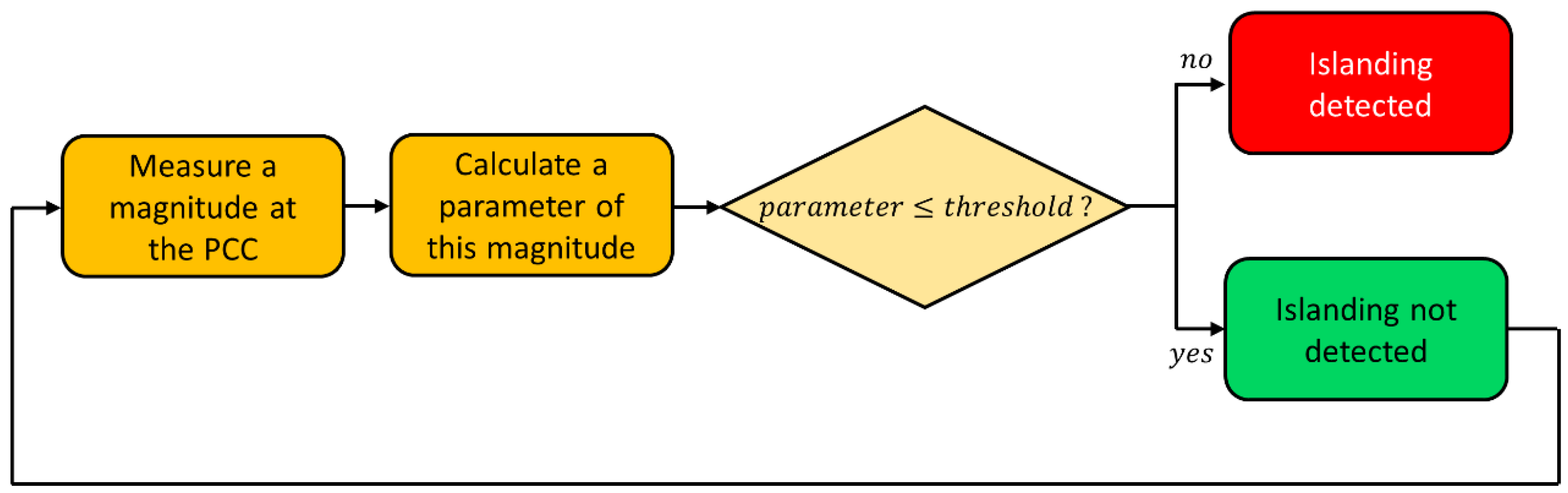
2.1. Passive Methods

Passive islanding detection methods are based on monitoring one or several significant magnitudes of the microgrid. A wide range of passive methods have been proposed in the literature [2,3,4,5,6,7,8,9,10,11] according to the magnitude measured (voltage, current, frequency, etc.) and the parameter calculated and monitored (the value of the magnitude, the rate of change, the harmonic content, etc.). The general implementation scheme of a passive method is shown in Figure 2.
Passive methods are well known and largely used because they are simple, inexpensive and because of the fact that they do not introduce disturbances such as variations of reactive power or harmonics that could degrade the power quality. However, they suffer from a non-detection zone (NDZ), which means that, under some conditions, islanding detection may be compromised, reducing their performance. The concept of NDZ as a performance index to evaluate different anti-islanding schemes is widely explained in reference [112].

2.1.1. Over Under Voltage (OUV) and Over Under Frequency (OUF)

This method consists of continuously monitoring the voltage and/or the frequency in the Point of Common Coupling (PCC) of the microgrid to verify if they are between the previously defined threshold values. When the microgrid is connected, these magnitudes are imposed by the utility grid, and they remain quite stable during normal operating conditions. When islanding occurs, the mismatch between the local generation and local consumption leads to deviations in voltage and frequency from the nominal values.
The drawback is that if local generation and local consumption mismatch is small when the islanding occurs, power and frequency deviations can be negligible. In consequence, there is an NDZ in which islanding is not detected.

2.1.2. Rate of Change of Output Power (RoCoP)

This method consists of monitoring the output power (active and/or reactive) at the PCC. If the variation rate is higher than a value, the method considers that islanding has occurred. This method is effective with unbalanced loads, it is quite fast (24–26 ms), and it has a small NDZ, being possible to obtain better results compared with other methods such as rate of change of voltage (RoCoV) [22,23]; however, it has a high error detection rate [16,24]. This method can fail in the cases where the microgrid generators do not have enough available power to compensate the load change (for example, if they are working at full load), which means that the output power will not change due to a load variation, and islanding will not be detected. Reference [25] presents an application of this method based on measuring the reactive power changes through the quotient ∂V/∂Q.

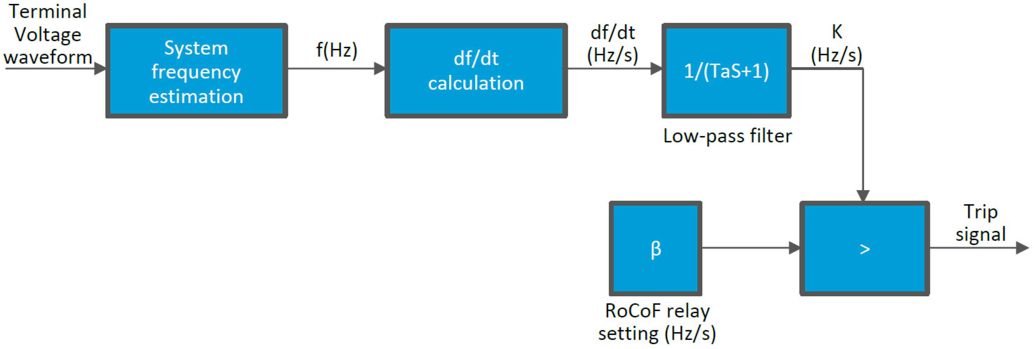
2.1.3. Rate of Change of Voltage (RoCoV)/Frequency (RoCoF)/Frequency over Output Power (RoCoFOP)

RoCoV and RoCoF consist of constantly measuring the variation rate of the voltage and the frequency at the PCC, respectively. Threshold values have to be chosen to avoid false positives, i.e., to recognize islanding as common disturbances of the grid that are comprised into the admissible range according to the grid codes [26,27].
There is a variation of this method called RoCoFOP that consists of measuring both the frequency and the power output of the generators and using this quotient to detect islanding [28]. It is especially effective in small systems where there are small load changes. It has a small NDZ, a detection time of around 100 ms and a very low error detection rate [16,29].
In reference [30], a technique is presented in which RoCoF is complemented by also analyzing the rate of change of the impedance (RoCoF-RoCoI) with the purpose of blocking RoCoF trips in case of a false positive.

2.1.4. Voltage Unbalance (VU)

This method is based on monitoring the voltage unbalance in the three-phase output power generated in the microgrid, according to the expression:
V U = V 2 V 1
where V 1 is the positive sequence component and V 2 is the negative sequence component.
The basis of this method is that changes in loading conditions cause changes in the V U provoked by harmonic distortion peaks [31]. The detection time is approximately 53 ms, and it has a low error detection rate but a large NDZ.

2.1.5. Voltage Phase Jump Detection

The phase angle jump is a parameter largely used to detect voltage dips when a fault occurs and is part of the protective relaying system [32,33,34,35]. During grid-connected mode, the voltage at PCC is imposed by the utility grid. When islanding occurs, the phase voltage at the PCC becomes dependent on the power factor of the local load, which usually results in a sudden change of its value, as seen in Figure 3. The voltage phase jump detection method measures this phase angle, normally using a phase-locked loop (PLL), to detect islanding. The method is easy to implement, but threshold values have to be carefully chosen because the start of big loads, such as motors, can cause transients of this magnitude. The performance depends on the local load; if the power factor is close to unity, islanding could not be detected as the phase jump will be negligible. Sometimes this method is named power factor detection or transient phase detection [2,6,36].
A variation of this method has been presented under the denomination phase monitoring [20]. It consists of monitoring the phase shift between the voltage and the current in the inverter output, considering that the phase of any load can be calculated from the expression [20]:
ϑ = tan 1 [ R ( ω C 1 ω L ) ]
where ω is the angular frequency of the grid, R the resistive load, L the inductive load and C the capacitive load.
Under normal operation, voltage and current should be in phase because the reference current for the inverter is synchronized with the fundamental voltage at the PCC. If islanding occurs, the voltage frequency can vary, causing a shift of the voltage vector and, consequently, the phase changes. This method can detect islanding as long as the load does not resonate at the grid frequency because, in this case, the phase does not vary. Then, the NDZ size is quite similar to the OUF method.
Reference [37] presents a method based on the phase angle of positive sequence voltage that has achieved zero NDZ and a detection time of 0.10 s in simulations considering the IEEE 1547 standard [1].
Another variation of this method has been presented under the denomination rate of change of phase angle difference (RoCPAD) [38]. Voltage and current signals are measured and transformed into phasors (amplitude, phase and frequency) to determine the current to voltage phase angle. The variation rate of this phase angle is constantly monitored and fluctuations faster than a defined value are interpreted as islanding. In reference [39], a method named rate of change of power factor angle, which has adaptive thresholds values, is presented.

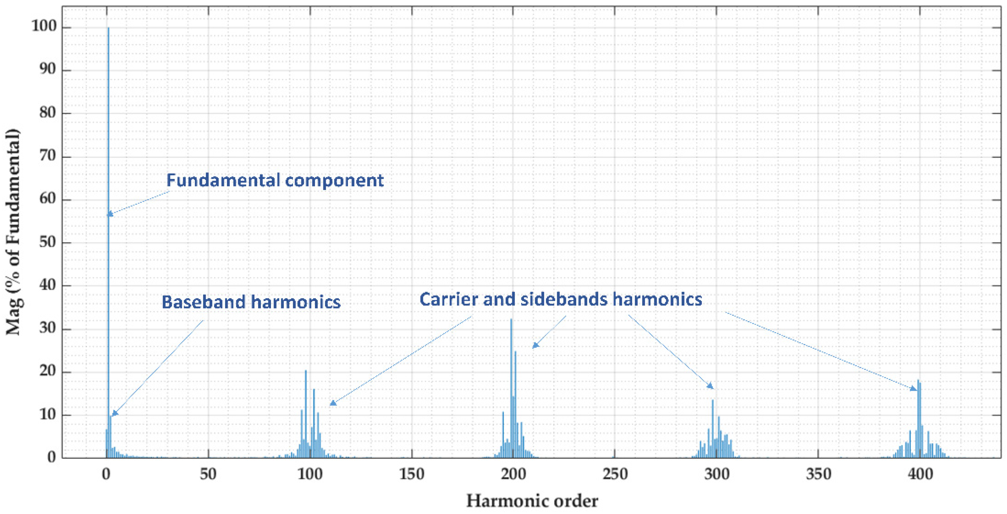
2.1.6. Harmonic Content of Voltage and Current

The output voltage waveform of the inverter is a square wave which is non-sinusoidal. Figure 4 show the harmonic content of the measured output voltage v A C ( t ) of a 6 kW and 5 kHz three-phase inverter.
Harmonic content detection methods can be classified into two types. To the first category belong those that are based on the measurement of the total harmonic distortion (THD) in voltage and/or current signals. The THD is a parameter that quantifies the total harmonic content of a signal, and it is calculated by the following expression (for voltage), with V 1 being the fundamental voltage and V k the k-order harmonic voltage:
T H D = k = 3 , 5 , 7 V k 2 V 1 2
In grid-connected operation, THD at PCC is highly influenced by the quality of supply of electricity. The harmonic content in distribution grids has been extensively studied, both on customer buses and at substations [113,114,115].
An important issue of this method is the selection of an appropriate threshold that provides good effectiveness and a low error detection rate. This threshold has to be lower than the THD produced in unintentional islanding but higher than the admissible THD of the grid, according to regulations such as EN 50160 [116].
This method can fail with high levels of reactive power (Q). Resistive, inductive and capacitive loads (RLC) can attenuate some frequencies and produce resonances in some other frequencies used by local inverters. Moreover, some voltage disturbances (for example, the connection of capacitor banks) can produce a transitory THD peak that could be interpreted as islanding. Due to these issues, this method is not often used [40].
Reference [41] presents a passive method measuring the THD of the current. Reference [42] presents a passive method based on calculating the THD of the voltage, combined with a voltage unbalance detection. This author has also developed protection schemes and circuits [43,44].
The other category of harmonic content detection methods is based on the measurement of some specific harmonics, especially the lowest ones (3rd, 5th and 7th) or some other ones produced locally, such as those generated by the switching of local inverters. The magnitude of these harmonics is different if the microgrid is connected or not connected to the grid; therefore, this kind of method can be effective to detect islanding.
Some examples of this possibility can be found in the literature. Reference [45] presents a passive islanding detection method based on measuring the 5th harmonic voltage at the PCC, which meets the requirements of IEEE 1547 standards [1]. Reference [46] presents a harmonic monitoring method based on the measurement of the 3rd and 5th harmonics, obtaining a high detection ratio with an optimal selection of the threshold values. Reference [31] presents a method based on voltage unbalance and current THD measurement.

2.1.7. Wavelet Transform

Wavelet transform is a generalization of short-time Fourier transform (STFT). It can be viewed as the projection of a signal into a set of basis functions named wavelets [47]. As the power is affected by variations when islanding occurs, this signal processing technique can track this magnitude in a certain frequency range. It can also process signals with time and frequency variation [48].
Many islanding detection methods based on wavelet transform have been developed. Reference [49] proposes a time-frequency detection algorithm based on monitoring the high-frequency components injected by PV inverters in which wavelet analysis is applied to obtain time localization of the islanding condition. The detection time is between 17.19 ms and 26.87 ms, the NDZ is small and it is tolerant to grid frequency and voltage variations. Reference [50] proposes an islanding detection technique based on the combination of a wavelet packet transform (WPT) and a probabilistic neural network (PNN), in which the PCC voltage is measured and processed by the WPT to find the normalized Shannon entropy (NSE) and the normalized logarithmic energy entropy (NLEE). In reference [51], a method that uses the transient signals generated during the islanding event has been developed, based on obtaining transient current signals from a discrete wavelet transform and applying pattern recognition techniques through probabilistic neural networks [16]. Reference [9] proposed a passive method based on wavelet transform and machine learning that achieves high accuracy.

2.1.8. Fourier and Other Mathematical Transform-Based Methods
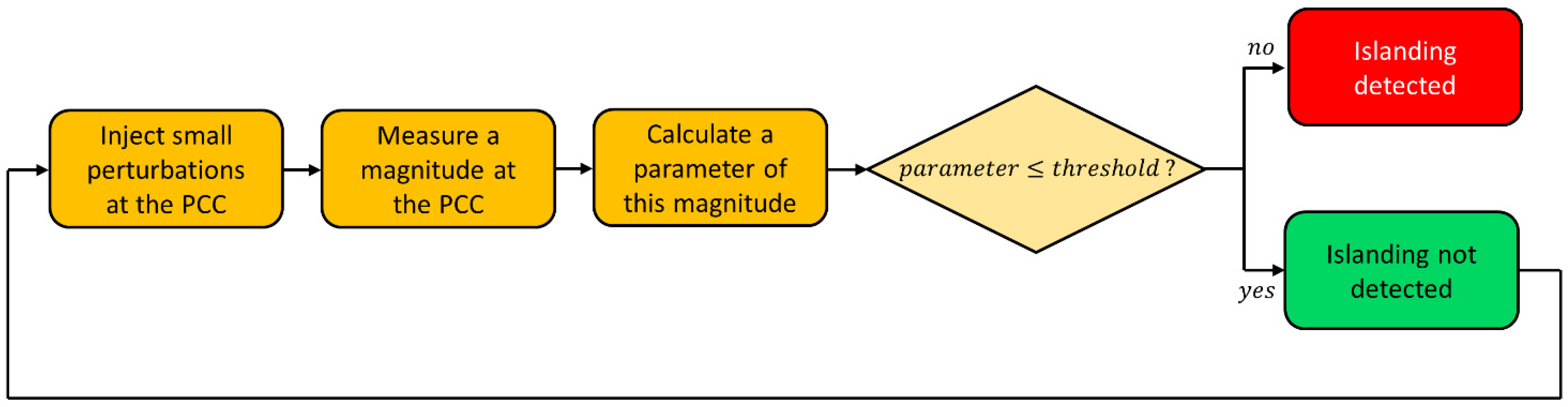
Fourier transform (FT) is a very powerful tool to analyze stationary signals [52], but it has some issues with non-stationary signals, transitory periods and fluctuations [53]. As a consequence, FT can be used to analyze the harmonic content in stationary mode but not to analyze fluctuating signals derived from islanding. Fourier-based methods are fast and efficient, but their computational requirements are high.
Many algorithms of fast Fourier transform (FFT) and discrete Fourier transform (DFT) have been developed to implement this transformation in digital systems. In reference [54], grid harmonic components at the PCC are monitored using a DFT to detect islanding because this harmonic content is different in grid-connected when compared to islanded mode. The detection time is less than 1 ms. Reference [55] presents a method based on measuring the impedance at the switching frequency of a local pulse width modulation (PWM) inverter, improving the resolution in the frequency domain using FFT. This method can work in a microgrid with multiple inverters, but different switching frequencies must be used.
In the literature, examples for the application of the s-transform [56], tt-transform [57] and Hilbert transform [58] can be seen.

2.2. Active Methods

Active islanding detection methods have been developed with the objective of increasing the performance of passive methods and reducing the NDZ. The main difference with passive methods is that active methods require the addition of small perturbations to the grid, as shown in Figure 5. These perturbations are calibrated to have negligible effects when grid-connected but to be noticeable when islanded. Then, active methods can be effective in detecting islanding in scenarios where many passive methods fail, for example, when local generation and consumption are in balance. However, they might cause a degradation in the quality of supply. Another disadvantage is that some of them present problems in power plants with more than one synchronous generator [59]. Next, a description of the most relevant active methods is presented.

2.2.1. Change of Impedance

This method consists of monitoring the source impedance, taking into account that the source impedance of the utility grid is smaller than the impedance of the local load. Then, the measured impedance will be much lower when grid-connected rather than when islanded, which allows the detection of this situation. A common way to measure the source impedance is by applying a near short-circuit with a low value impedance in each cycle, during an instant close to the zero-cross (for example, from 358° to 360°, as shown in Figure 6), and measuring the current [60]. Another way of implementing this method is to use a small high-frequency signal as the input of a voltage divider which has, in parallel, a fixed impedance and the system impedance [61].
This method has a small NDZ, a low error detection rate and a short detection time (about 10 ms). This method is suitable for small microgrids.

2.2.2. Active Impedance Detection

This method consists of introducing a perturbation in the current that produces a perturbation in the voltage, or vice versa. It also causes a perturbation in power. The voltage variation Δ V can be calculated as [2]:
Δ V = Δ P 2 R P
where Δ P is the perturbation in active power, R the resistance and P the active power.
An example of perturbation can be a notch in the signal, as shown in Figure 7, generated by varying the gain parameter in the inverter during this period of time. If the microgrid is connected to a strong enough utility grid (low impedance), the voltage or the current at PCC is not affected by the notch. However, if the monitored magnitude shows this notch, that means that the impedance at the inverter terminals is higher than it should be if the utility were connected, then islanding is detected [62]. This method usually presents a reduced NDZ, but does not work well with multiple local inverters.
Some variations of this method use the symmetrical component transformation or the direct-quadrature-zero transformation. For example, the technique known as negative sequence current injection consists of injecting a disturbance signal of negative sequence current to the PCC [63,64]. When grid-connected, this negative sequence will flow to the utility grid. However, when islanded, it will flow to the load, causing an unbalance in voltage. If this unbalance exceeds a threshold value, islanding will be detected. This technique improves the performance and the sensitivity to noise, and the NDZ can be negligible by using a periodic pulse signal as the reference signal of the negative-sequence current [65]. Reference [66] proposes to inject a signal based on DQ that is continuously on top of the DC component. The spectral content of this signal is confined to a very narrow band around the fundamental frequency, reducing the waveform distortion and avoiding the degradation of the power quality. The method proposed in [67] consists of injecting a disturbance signal through either the direct axis (it affects the amplitude of the voltage) or the quadrature axis (it causes a frequency deviation) and measuring these magnitudes at PCC. When grid-connected, the influence is negligible, but under islanded conditions, they have noticeable effects. Reference [68] shows an example of an algorithm consisting of generating disturbances by signal injection based on DQ implementation and detecting islanding by measuring voltage, frequency, active and reactive power and total harmonic distortion. This method can work with resistive, capacitive and inductive loads.

2.2.3. Harmonic Component Injection

This method can be found under several denominations: harmonic component injection, impedance at specific frequency, harmonic amplitude jump or high frequency signal injection. The method is based on the same principles as passive harmonic content of voltage and current but with the injection of a particular harmonic, normally in current, with a specific frequency. It is advisable to inject the frequency signal close to the PCC. In this method, it is considered that the harmonic content is introduced intentionally; in case it is introduced unintentionally, for example, caused by the inverter switching, the method should be classified as passive. Detection is based on the fact that the utility grid impedance is much lower than the load impedance at the harmonic frequency. The high-frequency impedance can be measured according to the output current and the measured output voltage of an LCL filter [69]. For most common implementations of this method, the NDZ is reduced, and they have short detection times (several ms) and a low error detection rate [16]. This is suitable with several inverters, but one of them should be the master [70]. However, this method produces a slight degradation in the power quality, increasing the THD of the signal.
In reference [71], an islanding detection technique based on measuring the harmonic impedance by injecting a current disturbance and measuring the resulting voltage is proposed. Reference [72] presents a way to detect islanding conditions based on introducing a low amplitude voltage signal with a frequency different from the fundamental frequency. Reference [69] proposes a detection method based on the injection of a high-frequency voltage to measure the high-frequency impedance of the grid. In reference [73], it is presented an islanding detection technique based on harmonic distortion that works introducing an active voltage locus to shift the reference active power. This signal is an amplification of each harmonic component by its order, which changes the voltage at PCC and breaks the power balance transferring the operating point outside the NDZ. Then, the OUV method can detect islanding by only measuring the voltage at the PCC. Paper [74] presents a method consisting of injecting a Gaussian modulated signal to cause voltage disturbances at the PCC that trips the ROCOF protection in case of islanding.
Mathematical transformations such as wavelet transform or Fourier transform can also be applied in harmonic-based methods. For example, the technique proposed in [75] combines the injection of a harmonic current with the application of the Goertzel algorithm (a Discrete Fourier Transform). Reference [76] proposes a method capable of working with multiple inverters also based on injecting harmonic currents with the same or different harmonic orders and monitoring the changes at the PCC, in which the Goertzel algorithm is employed to identify frequency components.

2.2.4. PLL Phase Perturbation

This method consists of slightly modifying the inverter current signal reference by adding a second harmonic disturbance signal at the PLL reference. The amplitude of this disturbance at the PCC depends on the impedance connected to this point. When grid-connected, the generated current is not affected in a noticeable way because the voltage will be stabilized by the utility grid. However, when the grid becomes unavailable, due to the added second harmonic, a deviation of the voltage at the PCC can be detected, which allows the detection of islanding.
This method causes a very small disturbance when grid-connected compared to other active islanding detection methods, such as active frequency drift or Sandia frequency shift. It has a small NDZ, a low error detection rate and a detection time of approximately 120 ms. In addition, it can be used with multiple local generators running in parallel [77].
Reference [78] uses this method by injecting a second harmonic at the inverter output current and observing the behavior of the voltage at the PCC, which depends on the impedance connected to the PCC in an islanding situation; this islanding detection is based on the Goertzel algorithm.

2.2.5. Slip Mode Frequency Shift (SMS)

This method, also called active phase shift, uses positive feedback in the PLL of the inverter to destabilize the phase when the utility grid is not present. With this method, the current-voltage phase angle is controlled to be a function of the PCC voltage. When the utility grid is connected, the frequency of the grid is not impacted because it is a solid reference that stabilizes the operating point. However, in islanded mode, this positive feedback causes instability due to the fact that the PLL acts in the wrong direction to correct the phase error. It is a simple method with small NDZ and is able to work with multiple inverters; however, it decreases the power quality.
Reference [79] presents an improvement of this method called automated phase shift, where an additional phase shift is introduced to improve the accuracy. In [80], an advanced version of the conventional SMS method is presented, in which the parameters are calibrated periodically by measuring the impedance of the local load. Performance and stability analysis of this method are also available [1,81,82].

2.2.6. Active Frequency Drift (AFD)

In this method, also known as frequency bias, the waveform of the current is slightly distorted, for example, increasing the frequency and remaining the signal at zero until the next cycle, as represented in Figure 8. This causes the inverter to give a distorted output current, as its frequency is slightly different than the voltage frequency at the PCC. When grid-connected, the utility grid maintains a stable frequency, and this disturbance has no effect. When islanded, the effects are noticeable, and the inverter tends to increase the frequency to eliminate the phase error. This tendency continues until frequency exits the OUF protection range and islanding is detected [2,15]. The chopping factor c of the perturbation is defined as follows, with T being the period and t c the zero-time:
c = 2 · t c T
This technique can be used with multiple local generators [83].

2.2.7. Sandia Frequency Shift (SFS)

This method, also called frequency set point, frequency positive feedback or active frequency drift with positive feedback, consists of introducing positive feedback in the frequency of the PCC voltage. When grid-connected, the utility grid maintains stability. When islanded, a slight deviation causes the frequency to increase or decrease progressively because of the positive feedback until it reaches the OUF threshold. The chopping frequency c f can be calculated from the next expression, in which c f 0 is the chopping factor, k S F S is the proportional gain, f i n v is the output frequency of the inverter and f g r i d is the frequency of the grid:
c f = c f 0 + k S F S ( f i n v f g r i d )
Several implementations of this method can be seen in [84,85,86,87]. It can be combined with the Sandia voltage shift method; both together are very effective [88]. The NDZ of this method and the dependence of the local active power consumption are analyzed in reference [89].

2.2.8. Sandia Voltage Shift (SVS)

Sandia voltage shift is based on adding positive feedback in the voltage at the PCC. During grid-connected operation, no significant variations should occur. In the case of a disconnection of the grid, a small variation of the voltage at the PCC is amplified by the positive feedback, quickly becoming out of the range of OUV and allowing the detection of the islanding. This method has a small NDZ, but it degrades the power quality [90].

2.2.9. Frequency Jump (FJ)

This method is a modification of the AFD method [2]. It consists of inserting dead zones into the output current waveform, but only in some cycles. There are many possibilities for this dithering pattern; a simple option would be, for example, a dead zone in every third cycle. If the microgrid is connected to the utility grid, the result is a modified inverter current that is occasionally distorted, but the utility grid dominates the voltage at the PCC, and it is not significantly affected. When working disconnected from the utility grid, islanding can be detected by a deviation in frequency (as in AFD) or by a variation in the PCC voltage frequency that matches the dithering pattern.

2.2.10. Variation of Active Power/Reactive Power

These two methods are based on the fact that when the microgrid is islanded, the voltage is a function of active power alone, whereas its frequency is a function of both active and reactive power.
Variation of active power, also called active power shift, consists of the injection of extra active power at the PCC that increases the amplitude of the voltage. If grid-connected, this increase will be compensated by the utility grid, but when islanded, it causes the actual voltage to be higher than the nominal voltage, which allows the detection of islanding [91].
In a similar way, variation of reactive power consists of introducing a continuous perturbation in the reactive power supplied by local generators, whereas voltage and frequency at the PCC are monitored. Then, this injection of reactive power will increase the frequency at the PCC if islanded, allowing the detection of islanding [92].
Both methods have a small NDZ but a high error detection rate, with the detection time of approximately 0.3 s in the first case and roughly 2 s in the second one. They degrade the power quality, and they also might cause instability issues.
Reference [93] proposes an islanding detection technique based on modifying the power-voltage (P-V) curves of the synchronous generators in a way that the microgrid maintains stability while grid-connected and loses its stability if islanded. As a result, OUV and OUF protection methods are sufficient to detect islanding, achieving an almost negligible NDZ.

2.2.11. Reactive Power Export Error Detection (RPEED)

This technique consists of forcing the generation units to produce some reactive power which cannot be supported unless the generator is connected to the grid. If grid-connected, it flows to the PCC and then to the utility grid. If islanding occurs, this reactive power cannot be injected into the grid, and there will be a difference between the reactive power setpoint and the reactive power generated. Consequently, islanding can be detected [94].

2.2.12. Reactive Power versus Frequency (Q-f) Droop

Reference [95] presents a technique consisting of the establishment of a Q-f droop curve that forces the synchronous generators to lose their stable operation when islanded, allowing detection by OUF protection.

2.2.13. Sudden Change in Impedance

This method, presented in [2], consists of installing two independent monitoring devices in series in the external and neutral conductor. Each of these independent units continuously monitors the connected grid by measuring voltage, frequency and impedance (injecting a small pulse). They can detect significant changes in impedance, which would occur if the utility were disconnected.

2.2.14. Virtual Capacitor/Virtual Inductor/Virtual Resistor

In virtual capacitor and virtual inductor methods, the local inverter acts as a virtual capacitor or a virtual inductor, respectively, having a fundamental frequency slightly lower or higher than the utility grid. Then, if the grid power becomes interrupted, the virtual capacitor/inductor operation of the local generator results in the change of load voltage in amplitude or frequency, even when local generation and consumption is balanced. Hence, the proposed method can immediately detect the islanding operation [96,97]. Both methods slightly degrade the power quality.
The virtual resistor method acts in a similar way. The inverter has an operating frequency slightly higher or lower than the nominal frequency of the grid. In grid-connected mode, the voltage and frequency at PCC will be stabilized by the utility grid. If disconnected from the utility grid, the voltage amplitude or frequency of the load will change. If the change exceeds a predefined threshold value, islanding will be detected [98].

2.3. Hybrid Methods

Hybrid methods are a combination of two or more methods, normally passive and active, with the purpose of increasing the effectiveness of passive methods without perturbing the power quality as much as most active methods do. Normally, the passive method is continuously working, and in case of possible islanding (if the parameter is over a minimum threshold but under a maximum threshold that directly trips the islanding detection), the active method is quick to launch, as shown in Figure 9. Hybrid strategies can work well if the selected methods complement each other efficiently. However, the complexity and the cost of hybrid methods are usually higher than using these methods individually. Many examples of hybrid methods can be found, some proposals are shown below.

2.3.1. Voltage Unbalance and Sandia Frequency Shift

Reference [99] proposes a method that combines voltage unbalance (passive) and Sandia frequency shift (active). The method that is continuously working is VU, which does not cause any disturbance. If VU detects a variation, SFS is launched to confirm that it is due to islanding and not for any other reason; therefore, positive feedback in frequency is applied. Then, if the frequency at PCC changes from the rated value to the SFS setpoint, islanding is detected. In any other case, the grid will impose the nominal frequency, and there will not be any noticeable change; therefore, islanding will not be detected.
In this way, the power quality degradation caused by these active methods is temporary and not permanent. This combination can detect islanding in 0.15–0.21 s, and its effectiveness depends mainly on the SFS. Then, in microgrids with non-synchronous generators, the effectiveness decreases.

2.3.2. Rate of Change of Voltage and Variation of Active/Reactive Power

In [100], a technique consisting of a combination between RoCoV (passive) and variation of active power (active) is proposed. RoCoV is continuously monitoring the voltage variation rate at PCC, and if this method detects potential islanding, variation of active power is launched. Then, the local generators inject an extra active power, which is compensated by the utility grid if connected. However, if the system is islanded, this extra active power will increase the voltage amplitude at PCC from the nominal value, allowing the detection of islanding. This combination provides the detection efficiency and low NDZ of active power variation, avoiding a degradation in the quality of supply for most of the time. It is very effective unless demand and generation perfectly match. The detection time is lower than 0.5 s.
In [101], a similar combination has been tested, but with variation of reactive power. In this case, islanding is detected by the variation in frequency.

2.3.3. Rate of Change of Voltage/Frequency and High-Frequency Voltage Perturbation

Paper [102] explains the development of a method based on a combination between RoCoV/RoCoF (passives) and high-frequency voltage perturbation (active), being the last one a case of harmonic component injection. Primary detection is conducted by RoCoV/RoCoF, measuring voltage and frequency at PCC. If potential islanding is detected, a high-frequency voltage perturbation is introduced by switching a high impedance load. When grid-connected, this perturbation is absorbed by the utility grid, but when islanded, the voltage variations at PCC caused by the injected perturbation allow the detection of islanding. The detection time is approximately 0.2 s, and it is very effective with different types of loads regardless of the quality factor. However, its effectiveness decreases in large microgrids (more than 1 kW).

2.3.4. Rate of Change of Reactive Power and Load Connecting Strategy

In reference [103], a technique that combines RoCoP (passive) and load connecting strategy (active) is presented. In the first step, the rate of change of reactive power technique is used to detect islanding. If this method suspects islanding, to discriminate it from other events, a load is connected to change the reactive power demand. When the microgrid is connected to the grid, the addition of this load will cause a negligible variation in d q / d t because the utility grid regulates the reactive power at PCC. However, in islanded mode, the system will observe a large difference between the demanded and the generated reactive power, which allows the detection of islanding. This method is quite effective if the connected load has an appropriate value, a small (but not zero) NDZ and a quick detection time (about 40 ms).

2.3.5. Sandia Frequency Shift and Reactive Power versus Frequency Droop

Reference [104] presents a hybrid method that aims to reduce the NDZ of SFS (active) using and Q-f droop curve method (also active). In SFS, the optimal value of the gain k S F S is directly proportional to the quality factor of the load. Then, if the quality factor of the load is high, the gain has to be also high, which can result in false-positive detection and also in instability issues. Adding some reactive power according to a Q-f droop curve allows high effectivity in islanding detection by monitoring the change of frequencies, maintaining k S F S in moderate values. In grid-connected mode, the demanded Q is supplied by the grid, but when islanded, the value of Q will be close to zero because generation units are set to minimize the generation of Q, producing a change in the frequency that can be detected. The effectiveness is high, and the detection time is approximately 1.4 s.

3. Overview of Remote Detection Methods

3.1. Communication Methods

Communication methods are based on the existence of communication between the power plant and the utility grid. The status of islanding or not islanding is directly sent, so the detection is immediate and without NDZ. In addition, they do not affect the quality of the power supply at all. However, communication methods are expensive because of the requirement of dedicated specialized hardware, and they could fail if communication interrupts for any reason [2,105,106]. They can be classified into two groups regarding the channel used to send data.

3.1.1. Power Line Carrier Communication (PLCC)

A PLCC system consists of a transmitter installed on the utility grid and a receiver on the microgrid that detects the signal of the transmitter. When islanding occurs, the receiver loses the signal, and consequently, it can be detected [107,108,109].

3.1.2. Standard Data Communication

This group comprises several methods consisting of the establishment of communication between the microgrid and the utility grid through an independent channel. A popular method called signal produced by disconnect consists of a signal that is only sent when the utility grid is disconnected. Some other communication methods are based on a SCADA that allows to remotely monitor the status of the power plant [110]. This requires some specific hardware (PC, PLC, etc.). Communication methods can also be based on a transfer trip scheme, which is complex and expensive [111].

3.2. Utility Methods

Methods of this category are based on the installation of some electric components, normally inductors or capacitors, on the utility grid side. The purpose is that in the case of islanding, the impedance at the PCC changes, making it possible to detect this situation. These methods can be fast and quite reliable without affecting the quality of the power supply, but they are expensive because of the requirement of some specific components.

Impedance Insertion

This method consists of installing a low-value impedance, usually a capacitor bank, on the grid side. The breaker of this component is normally open, and it only closes when islanding occurs. This causes a sudden variation in the reactive power consumption that can be easily detected by the microgrid [46].

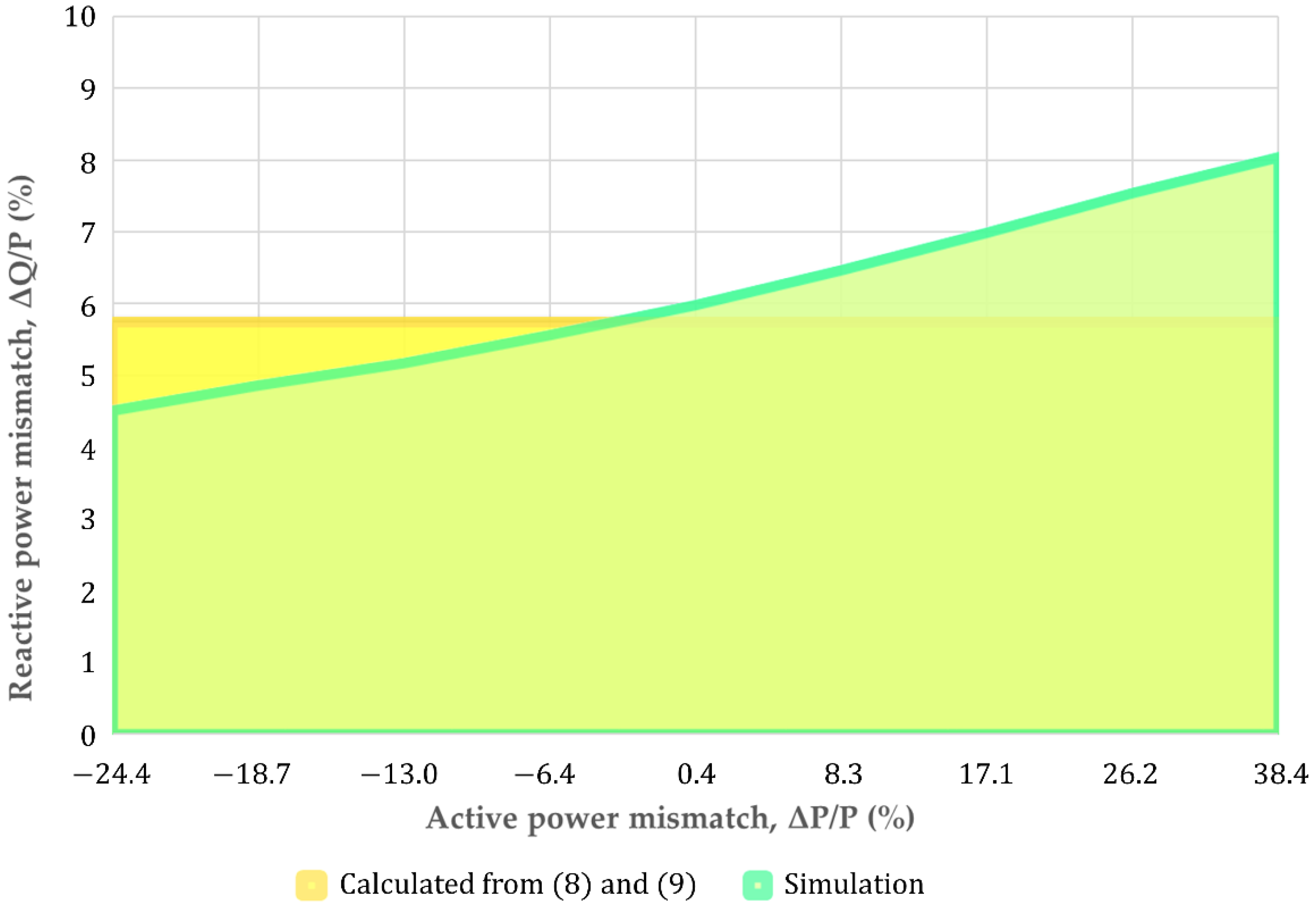
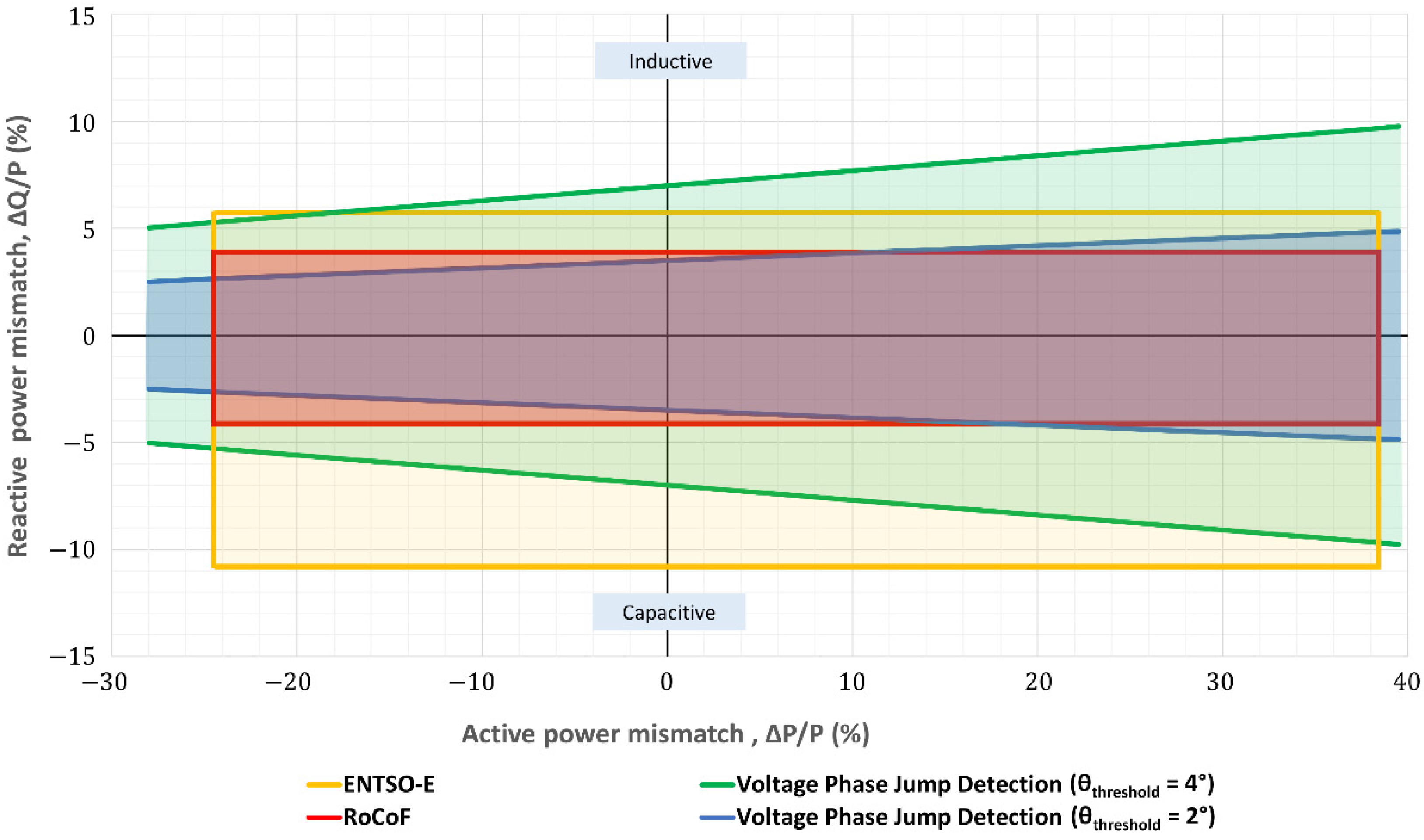
4. Non-Detection Zones: A Comparison between the Limits of ENTSO-E, Islanding Standards and Common Anti-Islanding Passive Methods

Islanding standards establish the test procedure for evaluating the reliability of islanding protections implemented in inverters. The experimental setup for the IEC 62116 [117] tests is shown in Figure 10.
Once the system reaches the steady state, the test begins when the switch S1 opens, and the time ( t t r i p ) while the inverter continues to feed the load before the islanding protection trip is measured. The test is carried out for different active and reactive power conditions. Table 6 summarizes the requirements of each standard and shows the quality factor ( Q f ), the required islanding trip time ( t t r i p ) and the normal range of operation for frequency and voltage. The quality factor ( Q f ) is defined as:
Q f = R · C L
where R is the effective load resistance, L the effective load inductance and C the effective load capacitance.
The normal operating range for inverters is defined by islanding standards, as is shown in Table 6. Regulations establish minimum periods of time during which an electricity generation module must be able to operate at a different frequency and voltage values, deviating from the nominal value, without disconnecting from the grid. In the European Union, the ENTSO-E regulation [118] is considered. According to each normal operating range defined by standards and national regulations, a particular NDZ is obtained for the OUV and OUF protections. In this work, ENTSO-E, IEC 62116, IEEE 929-2000 [119], IEEE 1547-2018 [1], the German VDE 0126 [120], the Australian AS4777.3-2005 [121] and the Japanese JEAC 9701 [122] have been evaluated. The NDZs obtained for these regulations are then compared with the NDZs obtained with different anti-islanding methods.
During the test or an islanding event, the active power ( Δ P ) and reactive power ( Δ Q ) mismatches are not enough to obtain the frequency ( f ) and voltage ( V ) out of their normal operating range, making islanding detection impossible. The NDZs can be obtained from the following equations that determine the relationship between active power and voltage and between reactive power and frequency [112]:
( V V m a x ) 2 1   Δ P P ( V V m i n ) 2 1
Q f · ( 1 ( f f m i n ) 2 )   Δ Q P Q f · ( 1 ( f f m a x ) 2 )
where V m i n ,   V m a x ,   f m i n and f m a x are the limits of the allowed operating range. Therefore, according to the different standards and the ENTSO-E, the NDZs calculated for OUV and OUF are shown in the fourth column in Table 6 and represented in Figure 11.
Both Equations (8) and (9), are derived for ∆P = ∆Q = 0. Therefore, when ∆P and ∆Q are different of zero, that is when there is a load mismatch between the AC power sources and the RLC load (calculated at the resonant frequency for Qf = 1). To show the accuracy of the approach, the value obtained from (8) and (9) are compared in Figure 12 with those of the simulation (case of inductive load). Hence, Equations (8) and (9) give a simple way to estimate the NDZ with acceptable accuracy.
As previously explained, RoCoF detection is used for the purposes of anti-islanding disconnection protection. However, as it is indicated in ENTSO-E, to ensure network stability, a power generating module should be capable of staying connected to the network and should operate at RoCoF up to a threshold specified by ENTSO-E. To obtain the RoCoF value, firstly, the frequency ( f ) is estimated from the measured voltage using a PLL. A 200-ms time window with a latency of 50 ms has been considered to obtain the frequency. Then, the time derivative of the frequency is computed, and a low-pass filter is applied to eliminate high RoCoF dynamics, being the smoothing trend obtained using a moving average filter. RoCoF is calculated [117] with a 500-ms time window and a latency of 250-ms, and it is compared with the settings. In Figure 13, this RoCoF schematic diagram is shown.
The NDZ for the anti-islanding scheme based on RoCoF detection has been derivated as follows. The RoCoF threshold is set to 2 Hz⁄s, the limits of frequency are then 49 Hz and 51 Hz, starting at an initial value of 50 Hz and considering in both cases that Q f = 1 . Hence, substituting the frequency limits into Equation (9), allows us to define the NDZ for RoCoF protection as indicated in Equation (10) and shown as the red color area in Figure 14:
4.12 % Δ Q P 3.88 %
On the other hand, the voltage phase jump detection is based on the measurement of the phase difference between the inverter output voltage and the inverter output current. If a voltage phase jump occurs during islanding, detection is possible. However, the threshold value setting ( θ t h r e s h o l d ) is critical to provide reliable islanding detection. The equation proposed in [112] to evaluate the NDZ of phase jump is:
| a r c t a n ( Δ Q P 1 + Δ P P ) | θ t h r e s h o l d
The election of θ t h r e s h o l d depends significantly on the accuracy of the voltage and current measurements at the PCC. As can be noticed in Figure 14, for high precision measurements ( θ t h r e s h o l d = 2 ° , lines in blue) the voltage phase jump detection method is able to reduce the NDZ obtained with the ENTSO-E criteria for voltage and frequency variations (yellow area in Figure 14). Likewise, the resulting NDZ increases when θ t h r e s h o l d increases. Figure 14 show the NDZ for θ t h r e s h o l d = 4 ° in green.
In the case of anti-islanding protection based on the measurement of voltage or current harmonics, the NDZ size depends on the harmonics chosen for the comparison and the set thresholds. For that reason, the quantitative determination of the associated NDZ is much more complex. In any case, the network can present contents in harmonics and, therefore, thresholds must be large enough to allow these contents in harmonics. Furthermore, the contents of the grid frequency harmonics due to the inverter depends on the power generated and on the power factor. The lower the power generated is, the higher the harmonics are. Likewise, there is a dependence on the load and its power factor. However, regarding the harmonics of the switching frequency, the harmonic content is due to the inverter itself, and that probably makes the use of these methods more feasible.

5. Future Trends

Interconnection codes lay down rules for distributed generators, which involves some NDZ. Only in the case of communication can the islanding methods’ NDZ can be avoided. However, this last technique is expensive. Small scale microgrids need to minimize software and hardware requirements; therefore, the utilization of advanced communication infrastructures is not the best option.
From an industrial point of view, research should be focused on non-expensive solutions capable of eliminating NDZ in order to overcome drawbacks. Furthermore, the speed and accuracy of detection are the main targets for future islanding detection method research.
On the one hand, learning algorithms and advanced digital signal processing techniques are potential tools for islanding detection, and they will continue to be developed, even though they can increase the hardware and software resources needed.
On the other hand, passive methods are inexpensive; therefore, more development is expected even if it is not easy. Regarding the harmonics of the switching frequency, the harmonic content is due to the inverter itself, and that makes the use of these methods more feasible.
Finally, active methods are effective in islanding detection; however, they inject small perturbations in a steady state. Avoiding the power quality degradation in a steady state will continue to be the challenge for active methods.

6. Conclusions

A comprehensive review of islanding detection methods has been conducted to help to define the best control to achieve a certain NDZ. These methods have been classified as can be seen in Figure 1. Their strengths and weaknesses have been evaluated in terms of detection time, effectiveness, error detection rate, NDZ, the possibility of working with multiple inverters and possible impact on the power quality (Table 1, Table 2, Table 3, Table 4 and Table 5).
Most islanding methods have limitations because of the requirements of grid codes that establish a range of voltage, frequency, etc., in which the local microgrid must remain connected to the utility grid. To analyze how it affects islanding detection, a comparison between the resulting NDZ obtained from the requirements of grid codes and the most common passive islanding detection methods have been performed. NDZs of these methods have been calculated analytically and by simulation and compared with the NDZs imposed by ENTSO-E and standards (Table 6).
It is worth noting that RoCoF protection is able to obtain an NDZ lower than the NDZs imposed by the grid codes irrespective of network conditions or parameter settings. However, only in the case of communication islanding methods can NDZ be eliminated.

Author Contributions

Conceptualization, J.A.C., S.M.-A. and M.G.-G.; methodology, J.A.C., D.C., S.M.-A. and M.G.-G.; investigation, J.A.C., D.C., S.M.-A. and M.G.-G.; validation, J.A.C., D.C., S.M.-A., M.G.-G. and H.L.; writing—original draft preparation, J.A.C., D.C. and M.G.-G.; writing—review and editing, J.A.C., S.M.-A., M.G.-G. and H.L.; supervision, J.A.C., S.M.-A., M.G.-G. and H.L.; funding acquisition, M.G.-G. and H.L. All authors have read and agreed to the published version of the manuscript.

Funding

This project has received funding from the ECSEL Joint Undertaking (JU) under grant agreement No 783158. The JU receives support from the European Union’s Horizon 2020 research and innovation programme and Italy, Germany, Belgium, Sweden, Austria, Romania, Slovakia, France, Poland, Spain, Ireland, Switzerland, Israel.

Institutional Review Board Statement

Not applicable.

Informed Consent Statement

Not applicable.

Acknowledgments

The authors wish to thank the technical support from the Research Group on Renewable Energy Integration (GENER) of the University of Zaragoza (funded by the Government of Aragon). In addition, the authors thank the International Electrotechnical Commission (IEC) for permission to reproduce Information from its International Standards. All such extracts are copyright of IEC, Geneva, Switzerland. All rights reserved. Further information on the IEC is available from www.iec.ch. IEC has no responsibility for the placement and context in which the extracts and contents are reproduced by the author, nor is IEC in any way responsible for the other content or accuracy therein.

Conflicts of Interest

The authors declare no conflict of interest.

Appendix A

In Table A1, the abbreviations and acronyms used in this manuscript are presented.
Table A1. List of abbreviations and acronyms used in this manuscript.
ACAlternating Current
AFDActive Frequency Drift
ASAustralian Standard
DCDirect Current
DFTDiscrete Fourier Transform
DGDiesel Generator
DQDirect Quadrature
ENTSO-EEuropean Network of Transmission System Operators for Electricity
EUEuropean Union
FFTFast Fourier Transform
FJFrequency Jump
FTFourier Transform
IECInternational Electrotechnical Commission
IEEEInstitute of Electrical and Electronics Engineers
JEACJapan Electric Association Code
LCLInductor (L), Capacitor (C), Inductor (L)
NDZNon-Detection Zone
NLEENormalized Logarithmic Energy Entropy
NSENormalized Shannon Entropy
OUFOver Under Frequency
OUVOver Under Voltage
PActive Power (also named Real Power)
PCPersonal Computer
PCCPoint of Common Coupling
PLCProgrammable Logic Controller
PLCCPower Line Carrier Communication
PLLPhase-Locked Loop
PNNProbabilistic Neural Network
PVPhotovoltaic
P-VPower-Voltage
PWMPulse Width Modulation
QReactive Power
Q-fReactive Power Frequency
RLCResistive (R), inductive (L) and capacitive (C)
RoCoFRate of Change of Frequency
RoCoFOPRate of Change of Frequency over Output Power
RoCoPRate of Change of Output Power
RoCoVRate of Change of Voltage
RoCPADRate of Change of Phase Angle Difference
RPEEDReactive Power Export Error Detection
SCADASupervisory Control And Data Acquisition
SFSSandia Frequency Shift
SMSSlip Mode Frequency Shift
STFTShort-Time Fourier Transform
SVSSandia Voltage Shift
THDTotal Harmonic Distortion
ULUnderwriters Laboratories
VDEVerband der Elektrotechnik
VUVoltage Unbalance
Wi-FiWireless Fidelity
WPTWavelet Packet Transform

References

  1. IEEE. IEEE Standard for Interconnecting Distributed Resources with Electric Power Systems; IEEE Std 1547–2018; IEEE: Piscataway, NJ, USA, 2018. [Google Scholar]
  2. Bower, W.; Ropp, M. Evaluation of Islanding Detection Methods for Utility-Interactive Inverters in Photovoltaic Systems; Technical Report; US Department of Energy: Washington, DC, USA, 2002.
  3. De Mango, F.; Liserre, M.; Dell’Aquila, A.; Pigazo, A. Overview of anti-islanding algorithms for PV systems. Part I: Passive methods. In Proceedings of the 12th International Power Electronics and Motion Control Conference, Portoroz, Slovenia, 30 August–1 September 2006; pp. 1878–1883. [Google Scholar]
  4. De Mango, F.; Liserre, M.; Dell’Aquila, A. Overview of Anti-Islanding Algorithms for PV Systems. Part II: Active methods. In Proceedings of the 12th International Power Electronics and Motion Control Conference, Portoroz, Slovenia, 30 August–1 September 2006; pp. 1884–1889. [Google Scholar]
  5. Mahat, P.; Chen, Z.; Bak-Jensen, B. Review of islanding detection methods for distributed generation. In Proceedings of the 3rd International Conference on Electric Utility Deregulation and Restructuring and Power Technologies, Nanjing, China, 6–9 April 2008; pp. 2743–2748. [Google Scholar]
  6. Teoh, W.Y.; Tan, C.W. An overview of islanding detection methods in photovoltaic systems. Int. J. Electr. Comput. Eng. 2011, 5, 1341–1349. [Google Scholar]
  7. Ahmad, K.N.E.K.; Selvaraj, J.; Rahim, N.A. A review of the islanding detection methods in grid-connected PV inverters. Renew. Sustain. Energy Rev. 2013, 21, 756–766. [Google Scholar] [CrossRef]
  8. Hosseinzadeh, M.; Rajaei Salmasi, F. Islanding Fault Detection in Microgrids—A Survey. Energies 2020, 13, 3479. [Google Scholar] [CrossRef]
  9. Khan, M.A.; Haque, A.; Bharath Kurukuru, V.S.; Saad, M. Islanding detection techniques for grid-connected photovoltaic systems-A review. Renew. Sustain. Energy Rev. 2022, 154, 1–21. [Google Scholar] [CrossRef]
  10. Timbus, A.; Oudalov, A.; Ho, C.N. Islanding detection in smart grids. In Proceedings of the IEEE Energy Conversion Congress and Exposition, Atlanta, Georgia, 12–16 September 2010; pp. 3631–3637. [Google Scholar]
  11. Lee, J.M. Islanding Detection Methods for Microgrids. Master’s Thesis, University of Wisconsin, Madison, WI, USA, 2011. [Google Scholar]
  12. Palm, S.; Schegner, P. Fundamentals of detectability and detection methods of unintentional electrical islands. In Proceedings of the IEEE Eindhoven PowerTech, Eindhoven, Netherlands, 29 June–2 July 2015; pp. 1–6. [Google Scholar]
  13. Laaksonen, H.; Hovila, P. Future-proof islanding detection schemes in Sundom Smart Grid. CIRED-Open Access Proc. J. 2017, 2017, 1777–1781. [Google Scholar] [CrossRef] [Green Version]
  14. Skocil, T.; Gomis-Bellmunt, O.; Montesinos-Miracle, D.; Galceran-Arellano, S.; Rull-Duran, J. Passive and active methods of islanding for PV systems. In Proceedings of the 13th European Conference on Power Electronics and Applications, Barcelona, Spain, 8–10 September 2009; pp. 1–10. [Google Scholar]
  15. Mastromauro, R. Grid Synchronization and Islanding Detection Methods for Single-Stage Photovoltaic Systems. Energies 2020, 13, 3382. [Google Scholar] [CrossRef]
  16. Raza, S.; Mokhlis, H.; Arof, H.; Laghari, J.A.; Wang, L. Application of signal processing techniques for islanding detection of distributed generation in distribution network: A review. Energy Convers. Manag. 2015, 96, 613–624. [Google Scholar] [CrossRef] [Green Version]
  17. Fuchs, E.; Masoum, M.A. Power Quality in Power Systems and Electrical Machines, 2nd ed.; Academic Press: Cambridge, MA, USA, 2015. [Google Scholar]
  18. Bhattacharyya, S.; Cobben, J.; Kling, W. Harmonic current pollution in a low voltage network. In Proceedings of the IEEE PES General Meeting, Minneapolis, MN, USA, 25–29 July 2010; pp. 1–8. [Google Scholar]
  19. Cobben, J.; Kling, W.; Myrzik, J. Power quality aspects of a future micro grid. In Proceedings of the International Conference on Future Power Systems, Amsterdam, The Netherlands, 18 November 2005; p. 5. [Google Scholar]
  20. Aljankawey, A.; Morsi, W.G.; Chang, L.; Diduch, C. Passive method-based islanding detection of renewable-based distributed generation: The issues. In Proceedings of the IEEE Electrical Power & Energy Conference, Halifax, NS, Canada, 25–27 August 2010; pp. 1–8. [Google Scholar]
  21. Liserre, M.; Teodorescu, R.; Blaabjerg, F. Stability of photovoltaic and wind turbine grid-connected inverters for a large set of grid impedance values. IEEE Trans. Power Electron. 2006, 21, 263–272. [Google Scholar] [CrossRef]
  22. Redfern, M.A.; Usta, O.; Fielding, G. Protection against loss of utility grid supply for a dispersed storage and generation unit. IEEE Trans. Power Deliv. 1993, 8, 948–954. [Google Scholar] [CrossRef]
  23. Redfern, M.A.; Barrett, J.; Usta, O. A new microprocessor based islanding protection algorithm for dispersed storage and generation units. IEEE Trans. Power Deliv. 1995, 10, 1249–1254. [Google Scholar] [CrossRef]
  24. Kim, M.S.; Haider, R.; Cho, G.J.; Kim, C.H.; Won, C.Y.; Chai, J.S. Comprehensive Review of Islanding Detection Methods for Distributed Generation Systems. Energies 2019, 12, 837. [Google Scholar] [CrossRef] [Green Version]
  25. Bakhshi, M.; Noroozian, R.; Gharehpetian, G.B. Passive anti-islanding scheme based on reactive power in the smart grids. In Proceedings of the Iranian Conference on Smart Grids, Tehran, Iran, 24–25 May 2012; pp. 1–7. [Google Scholar]
  26. Bakhshi-Jafarabadi, R.; Sadeh, J.; Chavez, J.d.J.; Popov, M. Two-level Islanding Detection Method for Grid-connected Photovoltaic System-based Microgrid with Small Non-detection Zone. IEEE Trans. Smart Grid 2020, 12, 1063–1072. [Google Scholar] [CrossRef]
  27. Vieira, J.C.M.; Freitas, W.; Huang, Z.; Xu, W.; Morelato, A. Formulas for predicting the dynamic performance of ROCOF relays for embedded generation applications. IEE PROC-C 2006, 153, 399–406. [Google Scholar] [CrossRef]
  28. Fu-Sheng, P.; Shyh-Jier, H. A detection algorithm for islanding-prevention of dispersed consumer-owned storage and generating units. IEEE Trans. Energy Convers. 2001, 16, 346–351. [Google Scholar] [CrossRef]
  29. Quoc-Tuan, T. New methods of islanding detection for photovoltaic inverters. In Proceedings of the IEEE PES Innovative Smart Grid Technologies Conference Europe (ISGT-Europe), Ljubljana, Slovenia, 9–12 October 2016; pp. 1–5. [Google Scholar]
  30. Marchesan, G.; Maresch, K.; Cardoso, G., Jr.; de Morais, A.P.; Muraro, M.R. Distributed Synchronous generation ride-through enhancement by anti-islanding protection blocking. Electr. Power Syst. Res. 2021, 196, 1–12. [Google Scholar] [CrossRef]
  31. Sung-Il, J.; Kwang-Ho, K. An islanding detection method for distributed generations using voltage unbalance and total harmonic distortion of current. IEEE Trans. Power Deliv. 2004, 19, 745–752. [Google Scholar]
  32. El Halabi, N.; García-Gracia, M.; Borroy, J.; Villa, J. Current phase comparison pilot scheme for distributed generation networks protection. Appl. Energy 2011, 88, 4563–4569. [Google Scholar] [CrossRef]
  33. García-Gracia, M.; El Halabi, N.; Borroy, S.; De Urtasun, L.G. Phase jump correction factor applied to the differential equation algorithm by an adaptive scheme. IET Gener. Transm. Distrib. 2011, 5, 266–275. [Google Scholar] [CrossRef]
  34. Wang, Y.; Bollen, M.H.; Xiao, X.Y. Calculation of the phase-angle-jump for voltage dips in three-phase systems. IEEE Trans. Power Deliv. 2014, 30, 480–487. [Google Scholar] [CrossRef]
  35. Espín-Delgado, Á.; Camarillo-Peñaranda, J.R.; Ramos, G. Characterization of phase-angle jump in radial systems using incremental voltage phasors. IEEE Trans. Ind. Appl. 2018, 55, 1117–1125. [Google Scholar] [CrossRef]
  36. Singam, B.; Hui, L.Y. Assessing SMS and PJD schemes of anti-islanding with varying quality factor. In Proceedings of the IEEE International Power and Energy Conference, Putra Jaya, Malaysia, 28–29 November 2006; pp. 196–201. [Google Scholar]
  37. Shafique, N.; Raza, S.; Bibi, S.; Farhan, M.; Riaz, M. A simplified passive islanding detection technique based on susceptible power indice with zero NDZ. Ain Shams Eng. J. 2022, 13, 101637. [Google Scholar] [CrossRef]
  38. Samui, A.; Samantaray, S. Assessment of ROCPAD relay for islanding detection in distributed generation. IEEE Trans. Smart Grid. 2011, 2, 391–398. [Google Scholar] [CrossRef]
  39. Xie, X.; Xu, W.; Huang, C.; Fan, X. New islanding detection method with adaptively threshold for microgrid. Electr. Power Syst. Res. 2021, 195, 1–11. [Google Scholar] [CrossRef]
  40. Osmanaj, S. An experimental study for the islanding detection by the harmonic distortion method and protection system of the inverter. Prz. Elektrotech. 2019, 1, 234–238. [Google Scholar] [CrossRef]
  41. Karegar, H.K.; Shataee, A. Islanding detection of wind farms by THD. In Proceedings of the Third International Conference on Electric Utility Deregulation and Restructuring and Power Technologies, Nanjing, China, 6–9 April 2008; pp. 2793–2797. [Google Scholar]
  42. Laaksonen, H. Advanced islanding detection functionality for future electricity distribution networks. IEEE Trans. Power Deliv. 2013, 28, 2056–2064. [Google Scholar] [CrossRef]
  43. Laaksonen, H. Securing passive islanding detection and enabling stable islanding with Q/f-droop control of DG unit. Int. Rev. Electr. Eng. 2014, 9, 592–602. [Google Scholar]
  44. Laaksonen, H. Protection scheme for island operated medium-voltage microgrid. Int. Rev. Electr. Eng. 2015, 10, 510–519. [Google Scholar] [CrossRef]
  45. Merino, J.; Mendoza-Araya, P.; Venkataramanan, G.; Baysal, M. Islanding detection in microgrids using harmonic signatures. IEEE Trans. Power Deliv. 2014, 30, 2102–2109. [Google Scholar] [CrossRef] [Green Version]
  46. Kobayashi, H.; Takigawa, K.; Hashimoto, E.; Kitamura, A.; Matsuda, H. Method for preventing islanding phenomenon on utility grid with a number of small scale PV systems. In Proceedings of the Conference Record of the 22nd IEEE Photovoltaic Specialists Conference, Las Vegas, NV, USA, 7–11 October 1991; pp. 695–700. [Google Scholar]
  47. Akansu, A.N.; Haddad, R.A. Wavelet Transform. In Multiresolution Signal Decomposition, 2nd ed.; Akansu, A.N., Haddad, R.A., Eds.; Academic Press: San Diego, CA, USA, 2001; pp. 391–442. [Google Scholar]
  48. Marques da Silva, D.; Costa, F.B.; Miranda, V.; Leite, H. Wavelet-based analysis and detection of traveling waves due to DC faults in LCC HVDC systems. Int. J. Electr. Power Energy Syst. 2019, 104, 291–300. [Google Scholar] [CrossRef]
  49. Pigazo, A.; Liserre, M.; Mastromauro, R.A.; Moreno, V.M.; Dell’Aquila, A. Wavelet-based islanding detection in grid-connected PV systems. IEEE Trans. Ind. Electron. 2008, 56, 4445–4455. [Google Scholar] [CrossRef] [Green Version]
  50. Ahmadipour, M.; Hizam, H.; Othman, M.L.; Mohd Radzi, M.A. An Anti-Islanding Protection Technique Using a Wavelet Packet Transform and a Probabilistic Neural Network. Energies 2018, 11, 2701. [Google Scholar] [CrossRef] [Green Version]
  51. Lidula, N.; Perera, N.; Rajapakse, A. Investigation of a fast islanding detection methodology using transient signals. In Proceedings of the IEEE Power & Energy Society General Meeting, Calgary, AB, Canada, 26–30 July 2009; pp. 1–6. [Google Scholar]
  52. Proakis, J.G.; Manolakis, D.G. Digital Signal Processing: Principles, Algorithms, and Applications, 3rd ed.; Prentice Hall: Upper Saddle River, NJ, USA, 1996. [Google Scholar]
  53. Gu, Y.H.; Bollen, M.H.J. Time-frequency and time-scale domain analysis of voltage disturbances. IEEE Trans. Power Deliv. 2000, 15, 1279–1284. [Google Scholar] [CrossRef]
  54. Kim, I.S. Islanding Detection Technique using Grid-Harmonic Parameters in the Photovoltaic System. Energy Procedia 2012, 14, 137–141. [Google Scholar] [CrossRef] [Green Version]
  55. Lee, S.H.; Park, J.W. New islanding detection method for inverter-based distributed generation considering its switching frequency. IEEE Trans. Ind. Appl. 2010, 46, 2089–2098. [Google Scholar] [CrossRef]
  56. Ray, P.K.; Mohanty, S.R.; Kishor, N. Disturbance detection in grid-connected distributed generation system using wavelet and S-transform. Electr. Power Syst. Res. 2011, 81, 805–819. [Google Scholar] [CrossRef]
  57. Khamis, A.; Shareef, H.; Wanik, M. Pattern recognition of islanding detection using tt-transform. J. Asian Sci. Res. 2012, 2, 607. [Google Scholar]
  58. Mahela, O.P.; Heydarian-Forushani, E.; Alhelou, H.H.; Khan, B.; Garg, A.R.; Al-Sumaiti, A.S. Combined Stockwell and Hilbert Transforms Based Technique for the Detection of Islanding Events in Hybrid Power System. In Proceedings of the IECON 2020 The 46th Annual Conference of the IEEE Industrial Electronics Society, Singapore, 18–21 October 2020; pp. 2531–2536. [Google Scholar]
  59. Xue, M.; Liu, F.; Kang, Y.; Zhang, Y. Investigation of active islanding detection methods in multiple grid-connected converters. In Proceedings of the IEEE 6th International Power Electronics and Motion Control Conference, Wuhan, China, 17–20 May 2009; pp. 2151–2154. [Google Scholar]
  60. Hopewell, P.D.; Jenkins, N.; Cross, A.D. Loss-of-mains detection for small generators. IEE Proc. Electr. Power Appl. 1996, 143, 225–230. [Google Scholar] [CrossRef]
  61. O’Kane, P.; Fox, B. Loss of mains detection for embedded generation by system impedance monitoring. In Proceedings of the 6th International Conference on Developments in Power System Protection, Nottingham, UK, 25–27 March 1997; pp. 95–98. [Google Scholar]
  62. Ropp, M.; Ginn, J.; Stevens, J.; Bower, W.; Gonzalez, S. Simulation and experimental study of the impedance detection anti-islanding method in the single-inverter case. In Proceedings of the IEEE 4th World Conference on Photovoltaic Energy Conference, Waikoloa, HI, USA, 7–12 May 2006; pp. 2379–2382. [Google Scholar]
  63. Karimi, H.; Yazdani, A.; Iravani, R. Negative-Sequence Current Injection for Fast Islanding Detection of a Distributed Resource Unit. IEEE Trans. Power Electron. 2008, 23, 298–307. [Google Scholar] [CrossRef]
  64. Nguyen Duc, T. Negative-sequence Current Injection of Dispersed Generation for Islanding Detection and Unbalanced Fault Ride-through. In Proceedings of the 46th International Universities’ Power Engineering Conference (UPEC), Soest, Germany, 5–8 September 2011; VDE. pp. 1–6. [Google Scholar]
  65. Bahrani, B.; Karimi, H.; Iravani, R. Nondetection Zone Assessment of an Active Islanding Detection Method and its Experimental Evaluation. IEEE Trans. Power Deliv. 2011, 26, 517–525. [Google Scholar] [CrossRef]
  66. Ye, Z.; Li, L.; Garces, L.; Wang, C.; Zhang, R.; Dame, M.; Walling, R.; Miller, N. A new family of active antiislanding schemes based on DQ implementation for grid-connected inverters. In Proceedings of the IEEE 35th Annual Power Electronics Specialists Conference (IEEE Cat. No. 04CH37551), Aachen, Germany, 20–25 June 2004; pp. 235–241. [Google Scholar]
  67. Hernandez-Gonzalez, G.; Iravani, R. Current injection for active islanding detection of electronically-interfaced distributed resources. IEEE Trans. Power Deliv. 2006, 21, 1698–1705. [Google Scholar] [CrossRef]
  68. Abdolrasol, M.G.M.; Mekhilef, S. Hybrid anti-islanding algorithm for utility interconnection of distributed generation. In Proceedings of the International Conference for Technical Postgraduates (TECHPOS), Kuala Lumpur, Malaysia, 14–15 December 2009; pp. 1–5. [Google Scholar]
  69. Reigosa, D.; Briz, F.; Charro, C.B.; García, P.; Guerrero, J.M. Active islanding detection using high-frequency signal injection. IEEE Trans. Ind. Appl. 2012, 48, 1588–1597. [Google Scholar] [CrossRef]
  70. Reigosa, D.; Briz, F.; Blanco, C.; García, P.; Guerrero, J.M. Active islanding detection for multiple parallel-connected inverter-based distributed generators using high frequency signal injection. IEEE Trans. Power Electron. 2013, 29, 1192–1199. [Google Scholar] [CrossRef] [Green Version]
  71. Shi, H.; Yang, Z.; Yue, X.; Hou, L.; Zhuo, F. Calculation and measurement of harmonic impedance for a microgrid operating in islanding mode. In Proceedings of the 7th International Power Electronics and Motion Control Conference, Harbin, China, 2–5 June 2012; pp. 356–361. [Google Scholar]
  72. Jun, L.; Xue-liang, H.; Xiao-hu, C.; Miao, X.; Wen, X. Two islanding detection circuits based on the impedance variation for the micro-grid. In Proceedings of the 2nd International Symposium on Power Electronics for Distributed Generation Systems, Hefei, China, 16–18 June 2010; pp. 859–863. [Google Scholar]
  73. Massoud, A.; Ahmed, K.; Finney, S.; Williams, B. Harmonic distortion-based island detection technique for inverter-based distributed generation. IET Renew. Power Gener. 2009, 3, 493–507. [Google Scholar] [CrossRef]
  74. Ferreira, D.A.; de Almeida, P.M.; Monteiro, H.L.M.; Cardoso, T.T.; Silva, L.R.M.; Duque, C.A. Plug-in active ROCOF method for islanding detection based on small-signal injection. Electr. Power Syst. Res. 2021, 201, 1–10. [Google Scholar] [CrossRef]
  75. Kim, J.; Kim, J.; Ji, Y.; Jung, Y.; Won, C. An Islanding Detection Method for a Grid-Connected System Based on the Goertzel Algorithm. IEEE Trans. Power Electron. 2011, 26, 1049–1055. [Google Scholar] [CrossRef]
  76. Patthamakunchai, S.; Konghirun, M.; Lenwari, W. An anti-islanding for multiple photovoltaic inverters using harmonic current injections. In Proceedings of the 9th International Conference on Electrical Engineering/Electronics, Computer, Telecommunications and Information Technology, Phetchaburi, Thailand, 16–18 May 2012; pp. 1–4. [Google Scholar]
  77. Ciobotaru, M.; Agelidis, V.G.; Teodorescu, R.; Blaabjerg, F. Accurate and less-disturbing active antiislanding method based on PLL for grid-connected converters. IEEE Trans. Power Electron. 2010, 25, 1576–1584. [Google Scholar] [CrossRef]
  78. Velasco, D.; Trujillo, C.; Garcera, G.; Figueres, E. An active anti-islanding method based on phase-PLL perturbation. IEEE Trans. Power Electron. 2010, 26, 1056–1066. [Google Scholar] [CrossRef] [Green Version]
  79. Liu, F.; Kang, Y.; Zhang, Y.; Duan, S.; Lin, X. Improved SMS islanding detection method for grid-connected converters. IET Renew. Power Gener. 2010, 4, 36–42. [Google Scholar] [CrossRef]
  80. Pahlevani, M.; Kaviri, S.M.; Jain, P.; Mohammadpour, B. Advanced slip mode frequency shift islanding detection method for single phase grid connected PV inverters. In Proceedings of the IEEE Applied Power Electronics Conference and Exposition (APEC), Long Beach, CA, USA, 20–24 March 2016; pp. 378–385. [Google Scholar]
  81. Lopes, L.A.C.; Huili, S. Performance assessment of active frequency drifting islanding detection methods. IEEE Trans. Energy Convers. 2006, 21, 171–180. [Google Scholar] [CrossRef]
  82. Mohammadpour, B.; Zareie, M.; Eren, S.; Pahlevani, M. Stability analysis of the slip mode frequency shift islanding detection in single phase PV inverters. In Proceedings of the IEEE 26th International Symposium on Industrial Electronics (ISIE), Edinburgh, UK, 19–21 June 2017; pp. 873–878. [Google Scholar]
  83. Lopes, L.A.; Zhang, Y. Islanding detection assessment of multi-inverter systems with active frequency drifting methods. IEEE Trans. Power Deliv. 2007, 23, 480–486. [Google Scholar] [CrossRef]
  84. Du, P.; Ye, Z.; Aponte, E.E.; Nelson, J.K.; Fan, L. Positive-Feedback-Based Active Anti-Islanding Schemes for Inverter-Based Distributed Generators: Basic Principle, Design Guideline and Performance Analysis. IEEE Trans. Power Electron. 2010, 25, 2941–2948. [Google Scholar]
  85. Zeineldin, H.H.; Kennedy, S. Sandia Frequency-Shift Parameter Selection to Eliminate Nondetection Zones. IEEE Trans. Power Deliv. 2009, 24, 486–487. [Google Scholar] [CrossRef]
  86. Zeineldin, H.; Conti, S. Sandia frequency shift parameter selection for multi-inverter systems to eliminate non-detection zone. IET Renew. Power Gener. 2011, 5, 175–183. [Google Scholar] [CrossRef]
  87. Reis, M.V.G.; Barros, T.A.S.; Moreira, A.B.; Nascimento, P.S.F.; Ruppert, E.F.; Villalva, M.G. Analysis of the Sandia Frequency Shift (SFS) islanding detection method with a single-phase photovoltaic distributed generation system. In Proceedings of the IEEE PES Innovative Smart Grid Technologies Latin America (ISGT LATAM), Montevideo, Uruguay, 5–7 October 2015; pp. 125–129. [Google Scholar]
  88. Stevens, J.; Bonn, R.; Ginn, J.; Gonzalez, S.; Kern, G. Development and Testing of an Approach to Anti-Islanding in Utility-Interconnected Photovoltaic Systems; (No. SAND2000–1939); Sandia National Laboratories Report SAND2000–1939; Sandia National Laboratories: Albuquerque, NM, USA, 2000.
  89. Zeineldin, H.H.; Salama, M.M. Impact of load frequency dependence on the NDZ and performance of the SFS islanding detection method. IEEE Trans. Ind. Electron. 2009, 58, 139–146. [Google Scholar] [CrossRef]
  90. El-Moubarak, M.; Hassan, M.; Faza, A. Performance of three islanding detection methods for grid-tied multi-inverters. In Proceedings of the IEEE 15th International Conference on Environment and Electrical Engineering (EEEIC), Rome, Italy, 10–13 June 2015; pp. 1999–2004. [Google Scholar]
  91. Jeraputra, C.; Enjeti, P.N. Development of a robust anti-islanding algorithm for utility interconnection of distributed fuel cell powered generation. IEEE Trans. Power Electron. 2004, 19, 1163–1170. [Google Scholar] [CrossRef]
  92. Jin Beom, J.; Hee Jun, K.; Soo Hyun, B.; Kang Soon, A. An improved method for anti-islanding by reactive power control. In Proceedings of the International Conference on Electrical Machines and Systems, Nanjing, China, 27–29 September 2005; pp. 965–970. [Google Scholar]
  93. Zeineldin, H.; Kirtley, J.L. A simple technique for islanding detection with negligible nondetection zone. IEEE Trans. Power Deliv. 2009, 24, 779–786. [Google Scholar] [CrossRef]
  94. Chowdhury, S.P.; Chowdhury, S.; Crossley, P.A. Islanding protection of active distribution networks with renewable distributed generators: A comprehensive survey. Electr. Power Syst. Res. 2009, 79, 984–992. [Google Scholar] [CrossRef]
  95. Zeineldin, H. A Q- f Droop Curve for Facilitating Islanding Detection of Inverter-Based Distributed Generation. IEEE Trans. Power Electron. 2009, 24, 665–673. [Google Scholar] [CrossRef]
  96. Chiang, W.J.; Jou, H.L.; Wu, J.C. Active islanding detection method for inverter-based distribution generation power system. Int. J. Electr. Power Energy Syst. 2012, 42, 158–166. [Google Scholar] [CrossRef]
  97. Jou, H.L.; Chiang, W.J.; Wu, J.C. Virtual inductor-based islanding detection method for grid-connected power inverter of distributed power generation system. IET Renew. Power Gener. 2007, 1, 175–181. [Google Scholar] [CrossRef]
  98. Chiang, W.J.; Jou, H.L.; Wu, J.C.; Wu, K.D.; Feng, Y.T. Active islanding detection method for the grid-connected photovoltaic generation system. Electr. Power Syst. Res. 2010, 80, 372–379. [Google Scholar] [CrossRef]
  99. Menon, V.; Nehrir, M.H. A Hybrid Islanding Detection Technique Using Voltage Unbalance and Frequency Set Point. IEEE Trans. Power Syst. 2007, 22, 442–448. [Google Scholar] [CrossRef]
  100. Mahat, P.; Chen, Z.; Bak-Jensen, B. A Hybrid Islanding Detection Technique Using Average Rate of Voltage Change and Real Power Shift. IEEE Trans. Power Deliv. 2009, 24, 764–771. [Google Scholar] [CrossRef] [Green Version]
  101. Yin, J.; Chang, L.; Diduch, C. A new hybrid anti-islanding algorithm in grid connected three-phase inverter system. In Proceedings of the 37th IEEE Power Electronics Specialists Conference, Jeju, Korea, 18–22 June 2006; pp. 1–7. [Google Scholar]
  102. Chang, W. A hybrid islanding detection method for distributed synchronous generators. In Proceedings of the 2010 International Power Electronics Conference, Sapporo, Japan, 21–24 June 2010; pp. 1326–1330. [Google Scholar]
  103. Laghari, J.A.; Mokhlis, H.; Bakar, A.H.A.; Karimi, M. A new islanding detection technique for multiple mini hydro based on rate of change of reactive power and load connecting strategy. Energy Convers. Manag. 2013, 76, 215–224. [Google Scholar] [CrossRef]
  104. Vahedi, H.; Noroozian, R.; Jalilvand, A.; Gharehpetian, G. Hybrid SFS and Q-f Islanding Detection Method for inverter-based DG. In Proceedings of the IEEE International Conference on Power and Energy, Kuala Lumpur, Malaysia, 29 November–1 December 2010; pp. 672–676. [Google Scholar]
  105. Funabashi, T.; Koyanagi, K.; Yokoyama, R. A review of islanding detection methods for distributed resources. In Proceedings of the IEEE Bologna Power Tech Conference Proceedings, Bologna, Italy, 23–26 June 2003. [Google Scholar]
  106. Kitamura, A.; Okamoto, M.; Hotta, K.; Takigawa, K.; Kobayashi, H.; Ariga, Y. Islanding prevention measures: Demonstration testing at Rokko test center for advanced energy systems. In Proceedings of the Conference Record of the Twenty Third IEEE Photovoltaic Specialists Conference-1993 (Cat. No. 93CH3283–9), Louisville, KY, USA, 10–14 May 1993; pp. 1063–1067. [Google Scholar]
  107. Ropp, M.; Larson, D.; Meendering, S.; McMahon, D.; Ginn, J.; Stevens, J.; Bower, W.; Gonzalez, S.; Fennell, K.; Brusseau, L. Discussion of a Power Line Carrier Communications-Based Anti-Islanding Scheme using a Commercial Automatic Meter Reading System. In Proceedings of the IEEE 4th World Conference on Photovoltaic Energy Conference, Waikoloa, HI, USA, 7–12 May 2006; pp. 2351–2354. [Google Scholar]
  108. Xu, W.; Zhang, G.; Li, C.; Wang, W.; Wang, G.; Kliber, J. A Power Line Signaling Based Technique for Anti-Islanding Protection of Distributed Generators—Part I: Scheme and Analysis. IEEE Trans. Power Deliv. 2007, 22, 1758–1766. [Google Scholar] [CrossRef]
  109. Wang, W.; Kliber, J.; Zhang, G.; Xu, W.; Howell, B.; Palladino, T. A Power Line Signaling Based Scheme for Anti-Islanding Protection of Distributed Generators—Part II: Field Test Results. IEEE Trans. Power Deliv. 2007, 22, 1767–1772. [Google Scholar] [CrossRef]
  110. Aphrodis, N.; Ntagwirumugara, E.; Vianney, B.J.M.; Mulolani, F. Design, Control and Validation of a PV System Based on Supervisory Control and Data Acquisition (SCADA) Viewer in Smartgrids. In Proceedings of the 5th International Conference on Control, Automation and Robotics (ICCAR), Beijing, China, 19–22 April 2019; pp. 23–28. [Google Scholar]
  111. Walling, R.A. Application of direct transfer trip for prevention of DG islanding. In Proceedings of the IEEE Power and Energy Society General Meeting, Detroit, MI, USA, 24–28 July 2011; pp. 1–3. [Google Scholar]
  112. Ye, Z.; Kolwalkar, A.; Zhang, Y.; Du, P.; Walling, R. Evaluation of anti-islanding schemes based on nondetection zone concept. IEEE Trans. Power Electron. 2004, 19, 1171–1176. [Google Scholar] [CrossRef]
  113. Emanuel, A.E.; Orr, J.A.; Cyganski, D.; Gulachenski, E.M. A survey of harmonic voltages and currents at distribution substations. IEEE Trans. Power Deliv. 1991, 6, 1883–1890. [Google Scholar] [CrossRef]
  114. Emanuel, A.E.; Orr, J.A.; Cyganski, D.; Gulachenski, E.M. A survey of harmonic voltages and currents at the customer’s bus. IEEE Trans. Power Deliv. 1993, 8, 411–421. [Google Scholar] [CrossRef]
  115. Nejdawi, I.; Emanuel, A.; Pileggi, D.; Corridori, M.; Archambeault, R. Harmonics trend in NE USA: A preliminary survey. IEEE Trans. Power Deliv. 1999, 14, 1488–1494. [Google Scholar] [CrossRef]
  116. CENELEC. EN 50160:2010/A2:2019 Voltage Characteristics of Electricity Supplied by Public Electricity Networks; German Institute for Standardisation: Berlin, Germany, 2019. [Google Scholar]
  117. IEC 62116:2014. Utility-Interconnected Photovoltaic Inverters. Test Procedure of Islanding Prevention Measures; International Electrotechnical Commission. Copyright © www.iec.ch; IEC: Geneva, Switzerland, 2014. [Google Scholar]
  118. ENTSO-E. Commission Regulation (EU) 2016/631 of 14 April 2016 establishing a network code on requirements for grid connection of generators. Off. J. Eur. Union 2016, L112, 1–68. [Google Scholar]
  119. The Institute of Electrical and Electronics Engineers. IEEE Std 929–2000 Recommended Practice for Utility Interface of Photovoltaic (PV) Systems; IEEE: Piscataway, NJ, USA, 2000. [Google Scholar]
  120. Deutsches Institut fur Normung (DIN); Verband der Elektrotechnik Elektronik Informationstechnik (VDE) e.V. Automatic Disconnection Device between a Generator and the Public Low Voltage Grid; VDE V 0126–1-1:2013–08; Deutsches Institut fur Normung (DIN): Berlin, Germany; Verband der Elektrotechnik Elektronik Informationstechnik (VDE) e.V.: Frankfurt, Germany, 2013. [Google Scholar]
  121. Committee EL-042 (Renewable Energy Power Supply Systems and Equipment). AS/NZS 4777.3–2005: Grid Connection of Energy Systems via Inverters—Part 3: Grid Protection Requirements; Standards Australia: Sydney, NSW, Australia, 2005. [Google Scholar]
  122. JESCE. Grid-interconnection Code. In JEAC 9701–2019; Japan Electric Association: Chiyoda-ku, Japan, 2019. [Google Scholar]
Figure 1. Classified list of the islanding methods evaluated in this work.
Energies 15 00460 g001
Figure 2. General scheme of passive methods.
Energies 15 00460 g002
Figure 3. Example of voltage signal jump monitored in the voltage phase jump detection method.
Energies 15 00460 g003
Figure 4. Harmonic content of the measured output voltage of a 6 kW and 5 kHz three-phase inverter.
Energies 15 00460 g004
Figure 5. General scheme of active methods.
Energies 15 00460 g005
Figure 6. Example of application time (switch on interval) in Change of Impedance method.
Energies 15 00460 g006
Figure 7. Example of sinusoidal voltage signal with notch perturbation.
Energies 15 00460 g007
Figure 8. Sinusoidal voltage signal with zero-time perturbation.
Energies 15 00460 g008
Figure 9. General scheme of hybrid methods.
Energies 15 00460 g009
Figure 10. Experimental arrangement for the IEC 62116 test procedure [117]. Reprint with permission [IEC 62116 ed.2.0]; Copyright 2014, IEC Geneva, Switzerland. www.iec.ch.
Energies 15 00460 g010
Figure 11. NDZ comparison of the NDZ of islanding standards and ENTSO-E for OUV and OUF.
Energies 15 00460 g011
Figure 12. Comparison between the NDZ calculated from (8) and (9) and the NDZ obtained by simulation for ENTSO-E and IEC 62116.
Energies 15 00460 g012
Figure 13. RoCoF schematic diagram.
Energies 15 00460 g013
Figure 14. NDZ comparison between ENTSO-E, RoCoF and voltage phase jump detection for two different θ t h r e s h o l d .
Energies 15 00460 g014
Table 6. Comparison between reference islanding standards and ENTSO-E [118].
Q f   1 t t r i p   2Normal Range of Operation 3NDZ 4
IEC 62116 [117]1t < 1 s ( f 0 1.5 )   Hz f ( f 0 + 1.5 )   Hz 6.28 % Δ Q P 5.74 %
t < 2 s 85 % V 115 % 24.38 % Δ P P 38.40 %
ENTSO-E [118]
(EU) 2016/631
( f 0 2.5 )   Hz f ( f 0 + 1.5 )   Hz 10.80 % Δ Q P 5.74 %
85 % V 115 % 24.38 % Δ P P 38.40 %
IEEE 929-2000
UL 1741 [119]
2.5t < 2 s 59.3   Hz   f   60.5   Hz 5.93 % Δ Q P 4.11 %
88 % V 110 % 17.35 % Δ P P 29.13 %
IEEE 1547-2018 [1]1t < 2 s 59.3   Hz   f   60.5   Hz 2.37 % Δ Q P 1.64 %
88 % V 110 % 17.35 % Δ P P 29.13 %
VDE 0126-1-1
Germany [120]
2t < 0.2 s 47.5   Hz f 50.2   Hz
80 % V 115 % 24.38 % Δ P P 56.25 %
AS4777.3-2005
Australia [121]
1t < 2 sSetting value (Hz)
Setting value (V)
Grid interconnection Code JEAC 9701-2019
(Japanese standard) [122]
0 (+rotating machinery)Passive:
t < 0.5 s
Setting value (Hz)
Setting value (V)
Active:
0.5 s < t < 1 s
Setting value (Hz)
Setting value (V)
1  Q f : Quality factor; 2  t t r i p : Required islanding trip time; 3  f 0 : Rated frequency; 4 NDZ: Non-Detection Zone.
Publisher’s Note: MDPI stays neutral with regard to jurisdictional claims in published maps and institutional affiliations.

