Article

A Convenient Method for the Accurate Calculation of Fin Efficiency of H-Type Fins Based on Linear Nomograms and Fitting Formulae

Key Laboratory of Energy Thermal Conversion and Control of Ministry of Education, School of Energy and Environment, Southeast University, Nanjing 210096, China
*
Author to whom correspondence should be addressed.
Energies 2022, 15(2), 456; https://doi.org/10.3390/en15020456
Submission received: 21 December 2021 / Revised: 31 December 2021 / Accepted: 4 January 2022 / Published: 10 January 2022

Abstract

:
Fin efficiency, as a measure of the effectiveness of the heat transfer enhancement, is of great importance in studying the heat transfer performance of H-type finned tube banks. The fin efficiency of square fins is adopted by most researchers as an alternative to that of H-type fins, which can create certain errors in the fin efficiency of H-type fins. For this paper, the linear nomograms and fitting formulae of fin efficiency of H-type fins are obtained by the definition method of fin efficiency based on numerous numerical simulations, and the results calculated by this method are verified by experimental data. On this basis, the effects of three geometric parameters (slit width, fin height, and fin thickness) and two thermal parameters (surface heat transfer coefficient and fin thermal conductivity) on the fin efficiency of H-type fins are also investigated and compared to those of square fins. The results indicate that the fin efficiency of H-type fins increases with the increment of fin thickness and thermal conductivity, and decreases with the increase of slit width, fin height, and surface heat transfer coefficient. Accordingly, the linear nomograms and fitting formulae for the fin efficiency of H-type fins, which are well compatible with experimental data, can help to facilitate further theoretical research and engineering application.

1. Introduction

The rational utilization of energy has become the great concern of the industry development all over the world, which puts forward the requirement of fortified heat exchange in the process of residual-heat utilization for the purpose of energy conservation and economic efficiency. Heat transfer enhancement is mainly realized by an “active method” and a “passive method” [1,2]. The “passive method” is independent of additional power from the external except for the power consumption in the transmission of the fluid medium. It mainly includes extended surfaces, flow manipulators, vortex generators, porous solids, and turbulators [3,4,5]. The extended surface by fins is one of the most widely used methods in theoretical research and engineering application, which aims to enhance the heat transfer by augmenting the heat-exchanging areas. Fins have been applied in the heat exchangers with thermoelectric cooling [6], condensation [7], latent heat energy storage [8], nanofluid [9], and other kinds of application. Finned tubes are basically classified into plain finned tubes, corrugated finned tubes, slotted finned tubes, and perforated finned tube with longitudinal vortex generator [10,11], among which the H-type finned tube is a relatively new type of the slotted finned tube. The advantages of H-type finned tubes can be summarized as high heat transfer efficiency, little flow resistance, low dust deposition, low wear, small size, and light weight [12,13,14,15]. Therefore, H-type finned tubes have great theoretical value and a huge range of prospects in applications.
The effectiveness of finned tubes to enhance heat transfer is generally measured by fin efficiency, which represents the heat dissipation performance of fins [16]; there is an iterative relationship between fin efficiency and the average surface heat transfer coefficient of finned tubes [3]. Therefore, before studying the heat transfer performance of H-type finned tubes, fin efficiency should be firstly considered as a crucial parameter. There are three main methods to calculate fin efficiency, namely the sector method [17], the equivalent circular fin method [3,18,19], and the method of definition of fin efficiency [20,21]. However, few methods have been applied in the calculation of the fin efficiency of H-type fins, and it is unfortunate that few authors have indicated how the fin efficiency was calculated in their papers [22,23,24,25]. Additionally, the fin efficiency of square fins calculated by the former Soviet linear nomogram has been adopted as an alternative to that of H-type fins [26,27,28], which creates a difference in the fin efficiency between H-type and square fins, especially in the circumstance of large slit width. It is of considerable inconvenience to employ the former Soviet linear nomogram of square fins in the iterations between the fin efficiency and the surface heat transfer coefficient, and the insufficiently detailed linear nomogram makes it difficult to ensure the accuracy of results. The former Soviet linear nomogram, considering the influence of exothermic inhomogeneity and the manufacturing process, is appropriate for the actual working conditions under long-term operation, which can create certain deviations from the results in experiments on newly invested fins or numerical simulations.
In addition, the method of definition of fin efficiency has been applied to the numerical simulations of H-type fins with trapezoidal, wedge configurations, and other novel modifications [20]. This method has also been employed in experimental investigations of H-type fins [14,21], where more accurate fin efficiency and surface heat transfer coefficient values were determined by iteration after the measurement of fin temperatures. The method of definition of fin efficiency provides a feasible way to the calculation in theoretical research and reference for the engineering application. Nevertheless, it is important to point out that the obtained correlations about fin efficiency of H-type fins from the experiments have some shortcomings. The surface heat transfer coefficient in the correlations obtained by Chen et al. [21] only relates to the air velocity and geometric parameters even though the thermal conductivity of fin materials and other variations also play important roles, and the scope of applicability of the correlations is limited to their own experimental setup.
There are certain errors in calculating the fin efficiency of H-type fins using the linear nomograms of square fins provided by [28], and it is inconvenient for researchers to obtain fin efficiency when iterating over the surface heat transfer coefficient. Therefore, in order to obtain a more accurate and convenient calculation method of fin efficiency for H-type fins, the definition method is chosen to numerically calculate the fin efficiency of H-type fins in this paper. The linear nomograms and fitting formulae of fin efficiency of H-type fins at different non-dimensional slit widths G/do are summarized based on numerous performed numerical simulations. The effects of three geometric parameters (slit width, fin height, and fin thickness) and two thermal parameters (surface heat transfer coefficient and thermal conductivity) are examined. The differences in the fin efficiency between H-type and square fins are also discussed, and, accordingly, the fin efficiency of square fins is calculated by the former Soviet linear nomogram and the similar numerical simulations, respectively. The linear nomograms and fitting formulae of fin efficiency of H-type fins can satisfy the requirements for the effective calculation of the surface heat transfer coefficient. This method has been applied to our current investigations and the next paper on the heat transfer and flow performance of H-type finned tube banks.

2. Model Description and Numerical Method

2.1. Physical Model

The schematic diagram of an H-type finned tube is shown in Figure 1a. The top and side views of the H-type fin are presented in Figure 1b,c, respectively. In this regard, it is assumed that the fin edge is considered to be adiabatic in simulations. The geometric parameters of the basic H-type finned tube are listed in Table 1.
In order to facilitate mathematical processing and maintain the basic characteristics of practical problems, reasonable assumptions regarding the heat transfer model of H-type fin are proposed as follows:
(1)
A heat dissipation model is applied to the H-type fin for this paper. The temperatures of fin base and the ambient fluid are constant as Tlj and Tf, respectively.
(2)
The thermal conduction along the thickness direction is ignored, and the heat conduction inside the H-type fin is two-dimensional.
(3)
The fin thermal conductivity is constant. The thermal contact resistance between the fin and the tube is not considered.

2.2. Governing Equations

Based on the simplified physical model obtained above, this can be described as a two-dimensional steady heat conduction problem, and the corresponding governing differential equation can be adopted [29]:
x ( λ t x ) + y ( λ t y ) + S = 0
Due to the constant physical property of the fin material, λ is a constant and S = q = −h(t−tf). The governing equation can be transformed into:
λ ( 2 t x 2 + 2 t y 2 ) + h ( t f t ) = 0
where λ is the fin thermal conductivity, W/(m·K); t is the temperature on the fin surface, °C; h is the average surface heat transfer coefficient combining radiation and convection, W/(m2·K); and tf is the ambient fluid temperature, °C.
In the governing equation, the temperature of the fin base is constant, and the fin edges are under the Neumann boundary conditions.

2.3. Data Reduction

Numerical simulations are employed in this paper to compute the temperature distribution of the fins, and the fin efficiency of H-type fins is assessed with the definition of the fin efficiency. For heat dissipation, the fin efficiency is defined as the ratio of the actual heat loss from the fin to the heat loss, which assumes that the entire fin surface is at the temperature of the fin base [24]; this is defined as follows:
η f = q 0 q max
where qmax is an ideal heat transfer given by
q max = F h ( t fb t f )
where F is the heat-exchanging area of the fin surface, m2; h is the average surface heat transfer coefficient combining radiation and convection, W/(m2·K); tfb is the temperature of the fin base, °C; and tf is the ambient temperature, °C.
q0 is the actual heat transfer. If the area of an element is set as Fij and the temperature of this element is set as tij, then q0 can be written as:
q 0 = F i j h ( t i j t f )
Therefore, it can be deduced that the numerical calculation formula of fin efficiency of H-type fins is expressed as:
η f = F i j h ( t i j t f ) F h ( t fb t f ) = F i j ( t i j t f ) F ( t fb t f )

2.4. Grid Independency

Pdetool in MATLAB (Producer: Beijing TianyanRongzhi; Location: Beijing, China) provides a powerful and flexible environment for the solution to the partial differential equations of two-dimensional finite elements. It mainly consists of three steps. The first step is defining a PDE problem, which includes the determinations of two-dimensional computational regions, boundary conditions, and PDE coefficients. The types of partial differential equations that can be solved by pdetool include elliptic, parabolic, hyperbolic, and eigenvalue types. In this paper, the PDE coefficients are determined by comparing the form of governing Equation (2) with the chosen elliptic type of PDE. The second step is solving differential equations, which includes meshing, discretizing the equation, and obtaining the numerical solution. The third step is graphically displaying results and exporting the data of each mesh. A specific case is demonstrated as having the same calculation procedures. The relevant parameters are shown in Table 2, and Figure 2 displays the mesh division and the simulated temperature contour in this case. As a result, the calculated value of fin efficiency is 0.777.
Additionally, in order to reduce mesh-dependency, the temperature difference of the upper right corner mesh (with the lowest temperature) is taken as the mesh dependence criterion. When the temperature difference is less than 0.01 °C through fining mesh, it is considered that the temperature distribution has no mesh-dependency. As shown in Table 3, when the number of grids reaches 2390, refining the grids does not make a significant change in the minimum temperature. Therefore, it is most appropriate to adopt the number of grids of 2390.

2.5. Validation of the Method

In order to validate the reliability of the numerical method, numerical calculations of the fin efficiency of H-type fins are carried out based on the geometric parameters and experimental data for bank D from [21]. The results are compared with the calculated data from the former Soviet linear nomogram [28] and the experimental results presented by Chen et al. [21]. The comparisons presented in Figure 3 reveal that the maximum deviation between the results from the former Soviet linear nomogram and the experiment is more than 10%, with the average deviation being around 6%. Since the former Soviet linear nomogram is more suitable to calculate the fin efficiency of square fins, its results are larger than both the experimental results and the numerical results of H-type fins. In addition, the different flow states at different points greatly affect the measured temperatures and surface heat transfer coefficient in the experiment, and the measured temperature cannot be completely symmetrical along the flow direction. All these factors can lead to the certain difference of the results between the experiments and simulations, but the numerical results from the method of definition of fin efficiency in this paper are roughly consistent with the experimental results and the absolute value of the relative error first decreases and then gradually increases within 0–6%. It is fully demonstrated that the numerical method of the fin efficiency of H-type fins in this paper is more accurate and credible than the other tested methods.

3. Results and Discussion

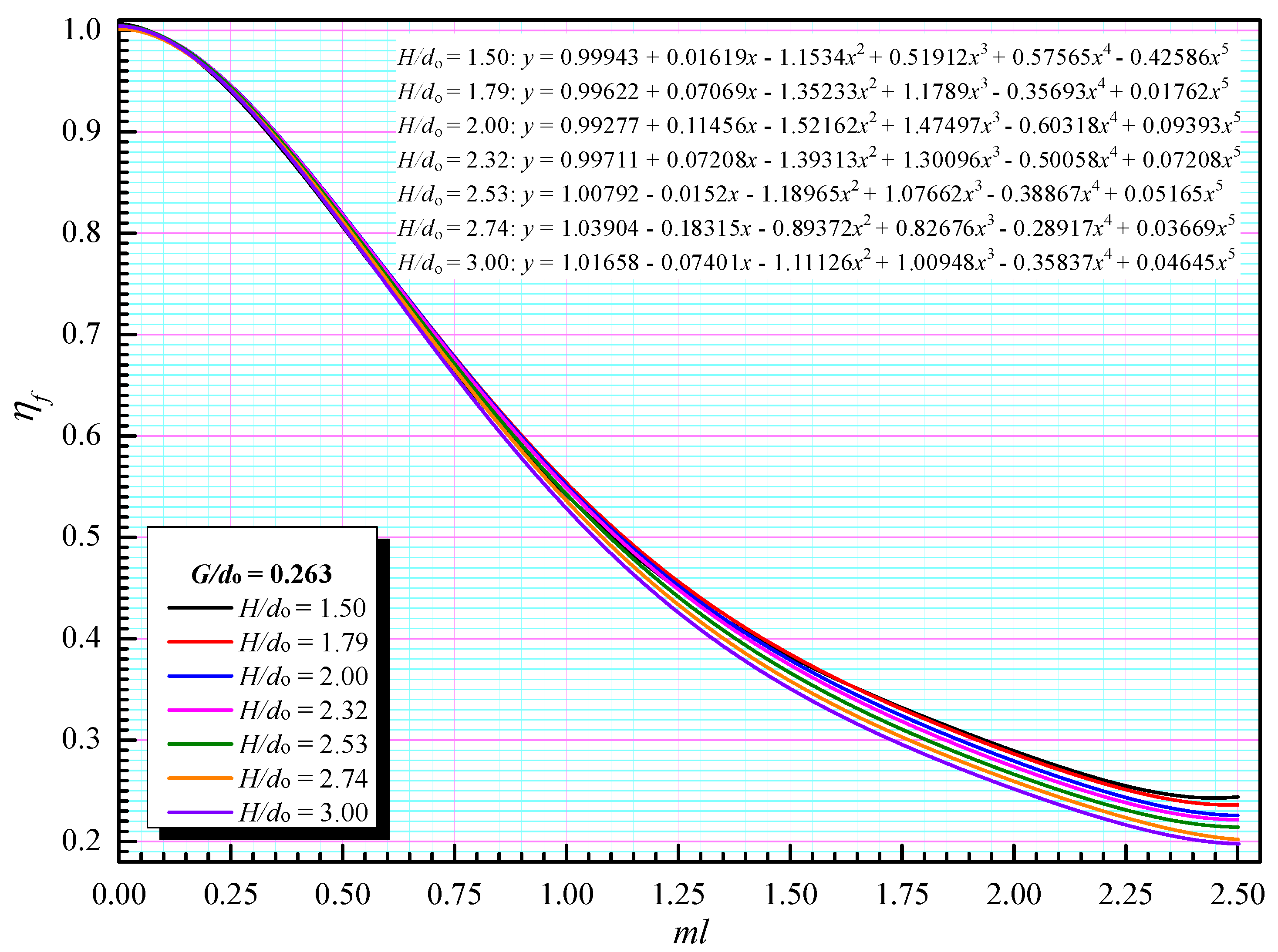
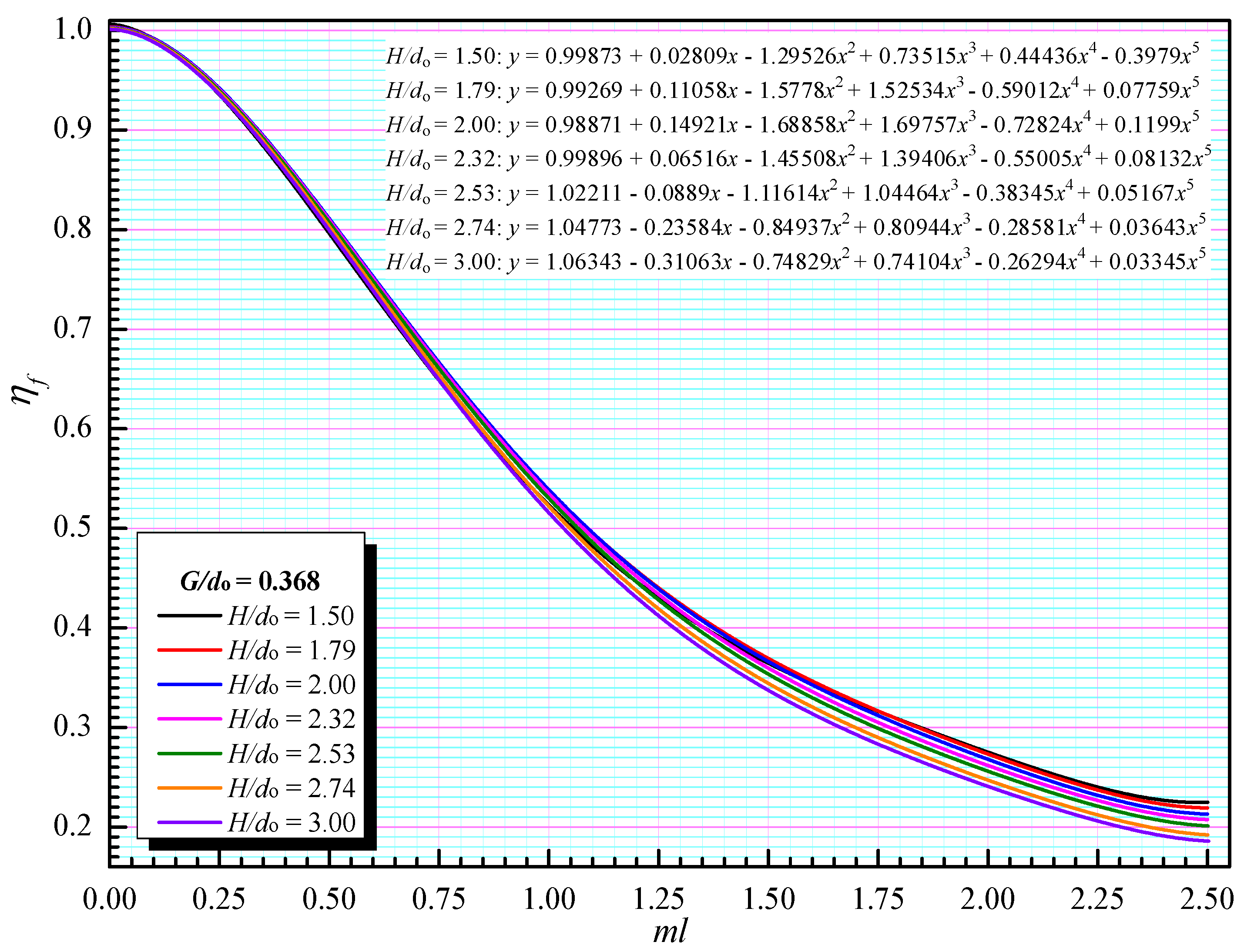
3.1. Linear Nomograms and Fitting Formulae of Fin Efficiency of H-Type Fins

In view of two-dimensional heat conduction model, it can be observed that the factors affecting the fin efficiency of H-type fins include the geometric parameters (slit width G, fin height H, and fin thickness δ), the fin thermal conductivity λ, and the surface heat transfer coefficient h. Numerous numerical calculations are carried out in this paper by varying these parameters via the method of controlled variates. Accordingly, the linear nomograms and fitting formulae of fin efficiency of H-type fins are summarized by fitting the data. The comprehensive influence of diverse parameters is considered in the linear nomograms of fin efficiency of H-type fins, which is similar to that of square fins. For the purpose of facilitating the calculation, ml is taken as the comprehensive variable of fin efficiency of H-type fins on the premise of equal fin height and fin width, i.e., H = A, where m = 2 h / ( λ δ ) and l = (H − do)/2.
In order to obtain more precise and careful linear nomograms, the effects of different tube diameters do and different non-dimensional slit widths G/do are investigated. The results shown in Figure 4 indicate that the fin efficiency of H-type fins hardly varies with tube diameters. When obtaining the linear nomograms and fitting formulae, the calculated data for fin efficiency of H-type fins under three diameters (32, 38, and 42 mm) is used in the fitting process. Figure 5 demonstrates the inverse relationship between the fin efficiency and ml at different ratios of G/do. Since the slit width of H-type fins hardly varies in a wide range in practice, the values of slit widths presented in this paper meet requirements of the general engineering application. The difference in the fin efficiency between the H-type fins with different ratios of G/do tends to first augment and then steadily maintain. Accordingly, it is necessary to make a valid distinction of the fin efficiency at different non-dimensional slit widths.
Three non-dimensional slit widths and several fin heights, which are usually applied in heat exchangers of power plants, are selected in the calculations to cover most of common conditions. Then, the corresponding values of fin efficiency of H-type fins are acquired by means of numerical simulations when ml ranges from 0 to 2.5. The linear nomograms and corresponding fitting polynomials derived from simulated data under three diameters (32, 38, and 42 mm) are shown in Figure 6, Figure 7 and Figure 8, where H = A and is uniformly expressed by H. The fin efficiency of H-type fins in the fitting formulae is expressed by y, and ml is expressed by x. The fin efficiency of H-type fins can be directly calculated according to the fitting formula without repeatedly querying the linear nomograms in the iterative process. Considering the heat transfer at the edge of H-type fins, the dimension in the direction of fin thickness needs to be extended to the dimension in the two-dimensional fin plane, so (H − do + 2δ)/2 is assigned to l when calculating the fin efficiency of H-type fins by means of the fitting formulae. These values adapt to the general structures of H-type fins and meet the requirements of common calculations. While H/do or G/do are not the given values in these linear nomograms, the interpolation method is recommended.
For the following section, the obtained linear nomograms and fitting formulae are employed to calculate the fin efficiency of H-type fins in the analysis of the effects of slit width G, fin height H, fin thickness δ, fin thermal conductivity λ, and surface heat transfer coefficient h. For the purpose of drawing distinctions between the fin efficiency of H-type and square fins with the corresponding sizes, the fin efficiency of square fins is calculated by the similar numerical simulation and the linear nomogram from the former U.S.S.R.

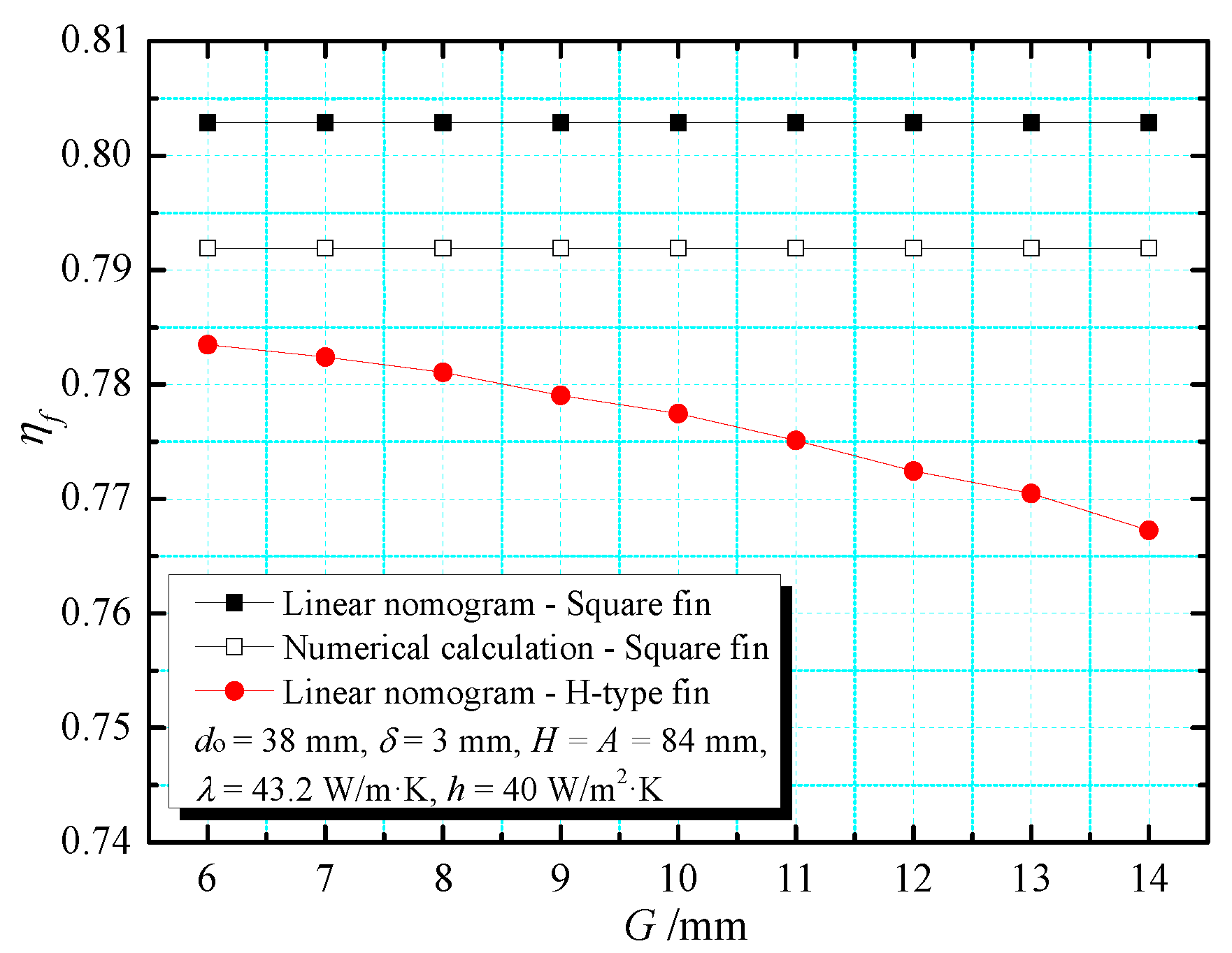
3.2. The Effect of Slit Width

For examining the effect of slit width on the fin efficiency of H-type and square fins, the slit width varies from 6 to 14 mm during the calculation. The effect of slit width on the fin efficiency of H-type and square fins is presented in Figure 9. It can be seen that when the non-dimensional slit width G/do is in the range of 0.158–0.368, the fin efficiency of H-type fins presents a persistent negative correlation with slit width. At the same time, whether or not the fin efficiency of square fins is calculated from the numerical simulations or from the former Soviet linear nomogram, the larger the slit width, the greater the difference in the fin efficiency between H-type and square fins is, which results from the reduction in surface area of H-type fins. Therefore, in the circumstance of larger slit width, the replacement of fin efficiency of square fins for that of H-type fins can create more obvious deviation.

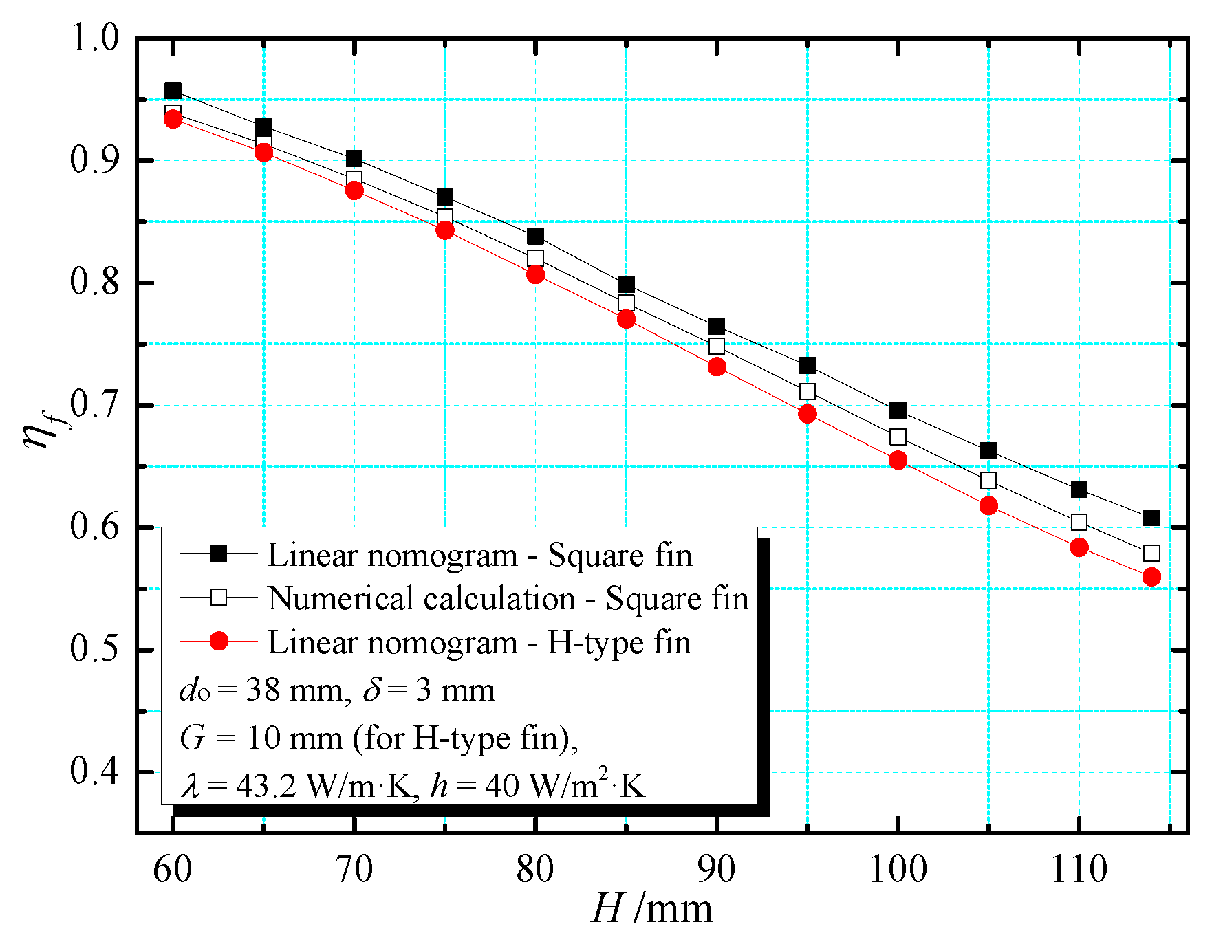
3.3. The Effect of Fin Height

Figure 10 displays the relation between fin efficiency and fin height within a variation range of the non-dimensional fin height H/do from 1.579 to 3 during a calculation in which the fin width is equal to the fin height. It can be seen that the fin efficiency of both H-type and square fins presents similar declines with increasing fin height due to the higher thickness of the thermal boundary layer. Furthermore, the increment of the fin height results in the increasing difference in the fin efficiency between the H-type and square fins. Compared with the fin efficiency of H-type fins, the deviations of the fin efficiency of square fins calculated from the former Soviet linear nomogram and numerical simulations are 2.3–8.9% and 0.5–3.4%, respectively.

3.4. The Effect of Fin Thickness

The correlation between the fin efficiency and the fin thickness is presented in Figure 11. When the fin thickness increases from 0.25 to 5 mm, the fin efficiency of square and H-type fins increases with basically the same trend. The results calculated from the numerical simulation and the former Soviet linear nomogram are 1.22–5.79% and 2.87–16.49%, respectively, higher than the fin efficiency of H-type fins. The difference in the fin efficiency between the H-type and square fins tends to gradually diminish with the increasing fin thickness.

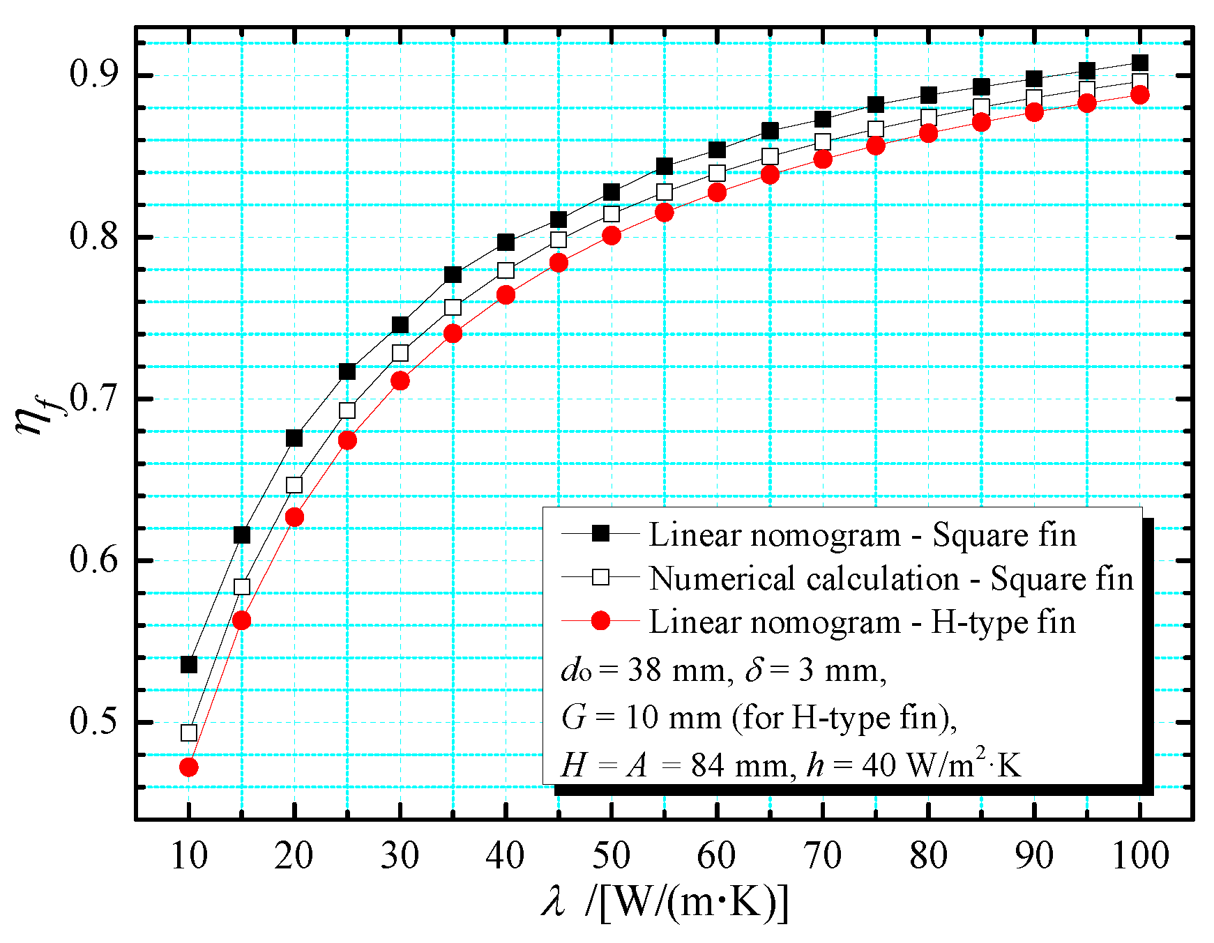
3.5. The Effect of Fin Thermal Conductivity

For examining the effect of fin thermal conductivity on the fin efficiency, calculations and simulations are conducted for the fin thermal conductivity from 10 to 100 W/(m·K), which is consistent with diverse materials. The results shown in Figure 12 reveal that the increment of the fin thermal conductivity contributes to the increase in the fin efficiency and the decline in the difference in the fin efficiency between the H-type and square fins regardless of whether the fin efficiency of square fins is calculated from the former Soviet linear nomogram or the numerical simulations. Thus, when conditions permit, a fin material with large thermal conductivity can be an appropriate option.

3.6. The Effect of Surface Heat Transfer Coefficient

Figure 13 presents the correlation between the fin efficiency and surface heat transfer coefficient within a variation range of 10–120 W/(m2·K). The increase in surface heat transfer coefficient not only decreases the fin efficiency but also augments the difference in the fin efficiency of H-type and square fins. It can be seen that compared to the fin efficiency of H-type fins, the average deviations of the fin efficiency of the square fins calculated from the former Soviet linear nomogram and numerical simulations are more than 4% and less than 2%, respectively. Accordingly, when replacing the fin efficiency of the square fins calculated by the linear nomogram for that of H-type fins, the deviation in surface heat transfer coefficient may be obvious.

4. Conclusions

For the sake of more accurate investigations into the heat transfer performance of H-type finned tube banks in the future, the definition method of fin efficiency is employed in this paper to obtain linear nomograms and fitting formulae under different geometric parameters. The former Soviet linear nomogram and the similar numerical simulations are applied to calculate the fin efficiency of square fins, and comparisons of fin efficiency between H-type and square fins are carried out. The numerical calculation is realized by the pdetool function of MATLAB. The following conclusions are obtained.
(1)
The linear nomograms and fitting formulae of fin efficiency of H-type fins obtained in different non-dimensional slit widths (G/do = 0.158, 0.263, and 0.368) and various non-dimensional fin heights (H/do = 1.5, 1.79, 2, 2.32, 2.53, 2.74, and 3) are presented, which are in good agreement with the experimental results. This method offers an accurate and reliable reference for theoretical research and engineering application.
(2)
An increasing slit width is found to decrease the fin efficiency of H-type fins. The larger the slit width, the greater the discrepancy in the fin efficiency between H-type and square fins is.
(3)
The increase in the fin thickness and fin thermal conductivity results in an increment of fin efficiency and a decline in the difference in the fin efficiency between H-type and square fins.
(4)
With increasing fin height and surface heat transfer coefficient, the fin efficiency of the H-type and square fins decreases while the difference in the fin efficiency between these two kinds of fins increases.
The method proposed in this paper is more convenient and accurate for calculating the fin efficiency of H-type fins, and it also facilitates the iteration between fin efficiency and surface heat transfer coefficient, which can be applied in most engineering cases. However, it is not applicable in some specific situations, such as the circumstance with large temperature difference between the fluid inside and outside the tube, which need to be further studied.

Author Contributions

Conceptualization, Y.F. and X.W.; methodology, Y.F.; software, Y.F.; validation, Y.F., X.W., and Z.S.; formal analysis, X.W.; investigation, Y.F., X.W., and Z.S.; resources, X.W.; data curation, Y.F.; writing—original draft preparation, Y.F.; writing—review and editing, X.W.; visualization, Y.F.; supervision, C.L.; project administration, C.L.; funding acquisition, X.W. and C.L. All authors have read and agreed to the published version of the manuscript.

Funding

This research was funded by the National Key R&D Program of China, grant number 2018YFB0605303.

Institutional Review Board Statement

Not applicable.

Informed Consent Statement

Not applicable.

Data Availability Statement

Not applicable.

Acknowledgments

We are indebted to Xin Wu and Cai Liang for their insightful suggestions on the original manuscript. All the editors and anonymous reviewers are gratefully acknowledged.

Conflicts of Interest

The authors declare no conflict of interest.

Nomenclature

Afin width, m
doouter diameter of the tube, m
Fheat-exchanging area of the fin surface, m2
Fijarea of an element, m2
Gslit width, m
haverage surface heat transfer coefficient combining radiation and convection, W⋅m−2⋅K−1
Hfin height, m
ptube wall thickness, m
q0actual heat transfer rate, W
qmaxideal heat transfer rate, W
tfin temperature, °C
tfambient fluid temperature, °C
tfbtemperature of the fin base, °C
tijtemperature of an element, °C
δfin thickness, m
λfin thermal conductivity, W⋅m−1⋅K−1

References

  1. Borunda, M.; Garduno-Ramirez, R.; Jaramillo, O.A. Optimal operation of a parabolic solar collector with twisted-tape insert by multi-objective genetic algorithms. Renew. Energy 2019, 143, 540–550. [Google Scholar] [CrossRef]
  2. Mehta, D.S.; Vaghela, B.; Rathod, M.K.; Banerjee, J. Heat transfer enhancement using spiral fins in different orientations of Latent Heat Storage Unit. Int. J. Therm. Sci. 2021, 169, 107060. [Google Scholar] [CrossRef]
  3. Lotfi, B.; Sundén, B. Development of new finned tube heat exchanger: Innovative tube-bank design and thermohydraulic performance. Heat Transf. Eng. 2020, 41, 1209–1231. [Google Scholar] [CrossRef] [Green Version]
  4. Mosavati, B.; Mosavati, M. A New Approach to Solve Inverse Boundary Design of a Radiative Enclosure with Specular–Diffuse Surfaces. J. Heat Transf. 2022, 144, 012801. [Google Scholar] [CrossRef]
  5. Mosavati, B.; Mosavati, M.; Kowsary, F. Inverse boundary design solution in a combined radiating-free convecting furnace filled with participating medium containing specularly reflecting walls. Int. Commun. Heat Mass Transf. 2016, 76, 69–76. [Google Scholar] [CrossRef]
  6. Xia, G.; Zhao, H.; Zhang, J.; Yang, H.; Feng, B.; Zhang, Q.; Song, X. Study on Performance of the Thermoelectric Cooling Device with Novel Subchannel Finned Heat Sink. Energies 2022, 15, 145. [Google Scholar] [CrossRef]
  7. Seol, S.-H.; Lee, S.-G.; Son, C.-H.; Yoon, J.-H.; Eom, I.-S.; Park, Y.-M.; Yoon, J.-I. Effects of Experimental Parameters on Condensation Heat Transfer in Plate Fin Heat Exchanger. Energies 2021, 14, 7681. [Google Scholar] [CrossRef]
  8. Sun, X.; Mahdi, J.M.; Mohammed, H.I.; Majdi, H.S.; Zixiong, W.; Talebizadehsardari, P. Solidification Enhancement in a Triple-Tube Latent Heat Energy Storage System Using Twisted Fins. Energies 2021, 14, 7179. [Google Scholar] [CrossRef]
  9. Alazwari, M.A.; Safaei, M.R. Non-Isothermal Hydrodynamic Characteristics of a Nanofluid in a Fin-Attached Rotating Tube Bundle. Mathematics 2021, 9, 1153. [Google Scholar] [CrossRef]
  10. Wang, Y.; He, Y.L.; Li, Y.S.; Cheng, Z.D. Theoretical study of air-side volatility effects on the performance of H-type finned heat exchangers in waste heat utilization. Numer. Heat Tranf. A-Appl. 2016, 70, 613–638. [Google Scholar] [CrossRef]
  11. Zheng, N.B.; Liu, P.; Shan, F.; Liu, Z.C.; Liu, W. Turbulent flow and heat transfer enhancement in a heat exchanger tube fitted with novel discrete inclined grooves. Int. J. Therm. Sci. 2017, 111, 289–300. [Google Scholar] [CrossRef]
  12. Zhao, X.B.; Tang, G.H.; Shi, Y.T.; Li, Y.K. Experimental study of heat transfer and pressure drop for H-type finned oval tube with longitudinal vortex generators and dimples under flue gas. Heat Transf. Eng. 2017, 39, 608–616. [Google Scholar] [CrossRef]
  13. Jin, Y.; Tang, G.H.; He, Y.L.; Tao, W.Q. Parametric study and field synergy principle analysis of H-type finned tube bank with 10 rows. Int. J. Heat Mass Transf. 2013, 60, 214–251. [Google Scholar] [CrossRef]
  14. Li, X.Z.; Zhu, D.S.; Sun, J.F.; Mo, X.; Yin, Y.D. Air side heat transfer and pressure drop of H type fin and tube bundles with in line layouts. Exp. Therm. Fluid Sci. 2018, 96, 146–153. [Google Scholar] [CrossRef]
  15. Wang, F.L.; He, Y.L.; Tang, S.Z.; Tong, Z.X. Parameter study on the fouling characteristics of the H-type finned tube heat exchangers. Int. J. Heat Mass Transf. 2017, 112, 367–378. [Google Scholar] [CrossRef]
  16. Chen, H.L.; Wang, C.C. Analytical analysis and experimental verification of trapezoidal fin for assessment of heat sink performance and material saving. Appl. Therm. Eng. 2016, 98, 203–212. [Google Scholar] [CrossRef]
  17. Perrotin, T.; Clodic, D. Fin efficiency calculation in enhanced fin-and-tube heat exchangers in dry conditions. In Proceedings of the 21st IIR International Congress of Refrigeration, Washington, DC, USA, 17–22 August 2003. [Google Scholar]
  18. Schmidt, T.E. Heat transfer calculations for extended surfaces. Refrig. Eng. 1949, 4, 351–357. [Google Scholar]
  19. Cuce, E.; Oztekin, E.K.; Cuce, P.M. Heat transfer enhancement in cylindrical fins through longitudinal parabolic perforations. Int. J. Ambient Energy 2019, 40, 406–412. [Google Scholar] [CrossRef]
  20. Bhale, P.; Kaushik, M.; Liaw, J.S.; Wang, C.C. Airside Performance of H-Type Finned Tube Banks with Surface Modifications. Energies 2019, 12, 584. [Google Scholar] [CrossRef] [Green Version]
  21. Chen, H.; Wang, Y.; Zhao, Q.; Ma, H.; Li, Y.; Chen, Z. Experimental Investigation of Heat Transfer and Pressure Drop Characteristics of H-type Finned Tube Banks. Energies 2014, 7, 7094. [Google Scholar] [CrossRef] [Green Version]
  22. Wang, Y.C.; Tang, G.H. Acid condensation and heat transfer characteristics on H-type fin surface with bleeding dimples and longitudinal vortex generators. Chin. Sci. Bull. 2014, 59, 4405–4417. [Google Scholar] [CrossRef]
  23. Zhao, X.B.; Tang, G.H.; Ma, X.W.; Jin, Y.; Tao, W.Q. Numerical investigation of heat transfer and erosion characteristics for H-type finned oval tube with longitudinal vortex generators and dimples. Appl. Energy 2014, 127, 93–104. [Google Scholar] [CrossRef]
  24. Jin, Y.; Yu, Z.Q.; Tang, G.H.; He, Y.L.; Tao, W.Q. Parametric study and multiple correlations of an H-type finned tube bank in a fully developed region. Numer. Heat Tranf. A-Appl. 2016, 70, 64–78. [Google Scholar] [CrossRef]
  25. Li, X.L.; Wang, S.Q.; Yang, D.L.; Tang, G.H.; Wang, Y.C. Thermal-hydraulic and fouling performances of enhanced double H-type finned tubes for residual heat recovery. Appl. Therm. Eng. 2021, 189, 116724. [Google Scholar] [CrossRef]
  26. Yang, Z.J.; Yuan, Y.C.; Yang, Y.Q.; Yang, X. Calculation for Fin Efficiency of H-Type Finned Elliptical Tube. Boil. Technol. 2019, 50, 18–23. [Google Scholar] [CrossRef]
  27. Liu, Y.Z.; Yuan, Y.C.; Xu, S.Y.; Wu, W.B. Experimental study on the characteristics of heat transfer and flow resistance for H-type finned tube banks. J. Univ. Shanghai Sci. Technol. 2004, 26, 457–460. [Google Scholar] [CrossRef]
  28. Gurewitch, A.M.; Kuznetsov, H.B. Thermal Calculation for Boilers-Standardization Method, 1973th ed.; China Machine Press: Beijing, China, 1976; p. 319. [Google Scholar]
  29. Roy, A.K.; Kumar, K. 2D heat conduction on a flat plate with Ti6Al4V alloy under steady state conduction: A numerical analysis. Mater. Today 2021, 46, 896–902. [Google Scholar] [CrossRef]
Figure 1. Schematic diagram of the H-type finned tube: (a) physical model; (b) top view of the H-type fin; (c) side view of the H-type fin.
Energies 15 00456 g001
Figure 2. Illustration of the H-type fin: (a) mesh in computational domain; (b) temperature contour.
Energies 15 00456 g002
Figure 3. Comparison of fin efficiency ηf for method validation.
Energies 15 00456 g003
Figure 4. Influence of three diameters do on the fin efficiency of H-type fins when G/do = 0.263 and H/do = 2.21.
Energies 15 00456 g004
Figure 5. Influence of different G/do on the fin efficiency of H-type fins when H/do = 2.21.
Energies 15 00456 g005
Figure 6. Linear nomograms and fitting formulae of fin efficiency at G/do = 0.158.
Energies 15 00456 g006
Figure 7. Linear nomograms and fitting formulae of fin efficiency at G/do = 0.263.
Energies 15 00456 g007
Figure 8. Linear nomograms and fitting formulae of fin efficiency at G/do = 0.368.
Energies 15 00456 g008
Figure 9. Influence of the slit width of fins on the fin efficiency of H-type and square fins.
Energies 15 00456 g009
Figure 10. Influence of the fin height on the fin efficiency of H-type and square fins.
Energies 15 00456 g010
Figure 11. Influence of the fin thickness on the fin efficiency of H-type and square fins.
Energies 15 00456 g011
Figure 12. Influence of fin thermal conductivity on the fin efficiency of H-type and square fins.
Energies 15 00456 g012
Figure 13. Influence of the surface heat transfer coefficient on the fin efficiency of H-type and square fins.
Energies 15 00456 g013
Table 1. Geometric parameters of the basic H-type finned tube in physical model.
H/mmA/mmG/mmδ/mmdo/mmp/mm
8484103385
Table 2. Parameters of H-type fins in the case.
Geometric Parametersdo/mmH and A/mmG/mmδ/mm
Values3884103
Thermal parameterstfb/°Ctf/°Cλ/(W/(m·K))h/(W/(m2·K))
Values702543.240
Table 3. Grid independence test.
Grid number1111173623902998
The lowest temperature55.478 °C55.449 °C55.433 °C55.437 °C
Temperature difference--0.029 °C0.016 °C0.004 °C
Publisher’s Note: MDPI stays neutral with regard to jurisdictional claims in published maps and institutional affiliations.

