Review

Role and Important Properties of a Membrane with Its Recent Advancement in a Microbial Fuel Cell

by
Aritro Banerjee
*,
Rajnish Kaur Calay
and
Fasil Ejigu Eregno
Faculty of Engineering Science and Technology, UiT—The Arctic University of Norway, 8514 Narvik, Norway
*
Author to whom correspondence should be addressed.
Energies 2022, 15(2), 444; https://doi.org/10.3390/en15020444
Submission received: 6 December 2021 / Revised: 3 January 2022 / Accepted: 4 January 2022 / Published: 9 January 2022
(This article belongs to the Special Issue Advances in Energy Materials and Clean Energy Technologies)

Abstract

:
Microbial fuel cells (MFC) are an emerging technology for wastewater treatment that utilizes the metabolism of microorganisms to generate electricity from the organic matter present in water directly. The principle of MFC is the same as hydrogen fuel cell and has three main components (i.e., anode, cathode, and proton exchange membrane). The membrane separates the anode and cathode chambers and keeps the anaerobic and aerobic conditions in the two chambers, respectively. This review paper describes the state-of-the-art membrane materials particularly suited for MFC and discusses the recent development to obtain robust, sustainable, and cost-effective membranes. Nafion 117, Flemion, and Hyflon are the typical commercially available membranes used in MFC. Use of non-fluorinated polymeric membrane materials such as sulfonated silicon dioxide (S-SiO2) in sulfonated polystyrene ethylene butylene polystyrene (SSEBS), sulfonated polyether ether ketone (SPEEK) and graphene oxide sulfonated polyether ether ketone (GO/SPEEK) membranes showed promising output and proved to be an alternative material to Nafion 117. There are many challenges to selecting a suitable membrane for a scaled-up MFC system so that the technology become technically and economically viable.

Graphical Abstract

1. Introduction

Many wastewater treatment techniques are used to remove contaminants from wastewater so that it can be returned safely to the water cycle. Typically, these include anaerobic digestion, aerobic activated sludge process, chemical precipitation, coagulation, flocculation, neutralization, adsorption, etc. These technologies require energy for operating and dealing with sludge management issues. Anaerobic digestion also generates sewage/biogas while effectively treating the sewage. Biogas is a mixture of methane (CH4), carbon dioxide (CO2), and water (H2O). The process of generating methane is called methanogenesis, and the microorganism involved in the process are methanogens. Methane can be used as fuel for heating, transport or generating electricity.
On the other hand, in a microbial fuel cell (MFC), the electroactive microorganism called exoelectrogen consumes organic matter present in wastewater and converts it directly into electricity. The microorganism oxidizes the organic matter and produces H+ ions (protons) and electrons in the anodic chamber. Protons are allowed to migrate towards the cathode chamber through the proton exchange membrane, and the electrons are made to flow via an external circuit to the cathode, where the reduction of H+ ion takes place.
Barnett Cohen observed this phenomenon in 1931 and created microbial half fuel cells (MFC) that, when connected in series, were capable of producing over 35 volts with only a current of 2 milliamps [1]. Over the years, it has been shown that MFC technology has potential for wastewater treatment and energy generation. There are other types of devices that generate electricity directly from fuel, such as polymer electrolyte membrane fuel cell (PEM), reverse polymer electrolyte membrane fuel cell (RePEM) and store energy such as redox flow batteries (RFB) which requires heavy metals [2,3]. The unique capability of MFC is to treat wastewater and produce electricity from microbial activity. Microorganisms not only reduced organic matter in the wastewater, but recent studies have found metal-reducing microorganisms that can also treat wastewater containing heavy and toxic metals [4,5]. PEM fuel cell requires an external source of hydrogen and oxygen gases to run the system [6]. In comparison, MFC is eco-friendly and self-sustainable technology to produce energy from waste material.
There are several papers in the last few decades that investigated MFCs for removal of BOD and COD [7], removal of toxic and heavy metals [8], and of course, generating electricity simultaneously [9]. Other applications include biosensors [10,11], bioremediations [12], nitrification and denitrification [13]. Some researchers also demonstrate the removal of various salts from saline water [14,15]. By modifying MFC’s architecture and operating conditions, the technology can be used to produce hydrogen. It is claimed that less energy is required compared to the electrolysis of H2O to produce hydrogen [16]. The researchers showed that carbon dioxide could be reduced in the anodic chamber to form methane gas [17]. However, many of these findings are preliminary studies at the laboratory level. In order to develop an application based MFC system such as removing heavy metals from wastewater, the design and operating conditions of the MFC must be enhanced [18]. The architecture and materials of the key components such as electrodes and membranes are critical for the optimal performance of the MFC [19].
This paper discusses the role of the proton exchange membrane on the overall performance of MFC. It also describes the design strategy for choosing the suitable membrane based on the application of the MFC system for enhancing the overall performance of the system. Here, the state-of-the-art of the latest advancement of membrane and analysis of the existing knowledge on membrane materials and their impact on performance and cost are presented.

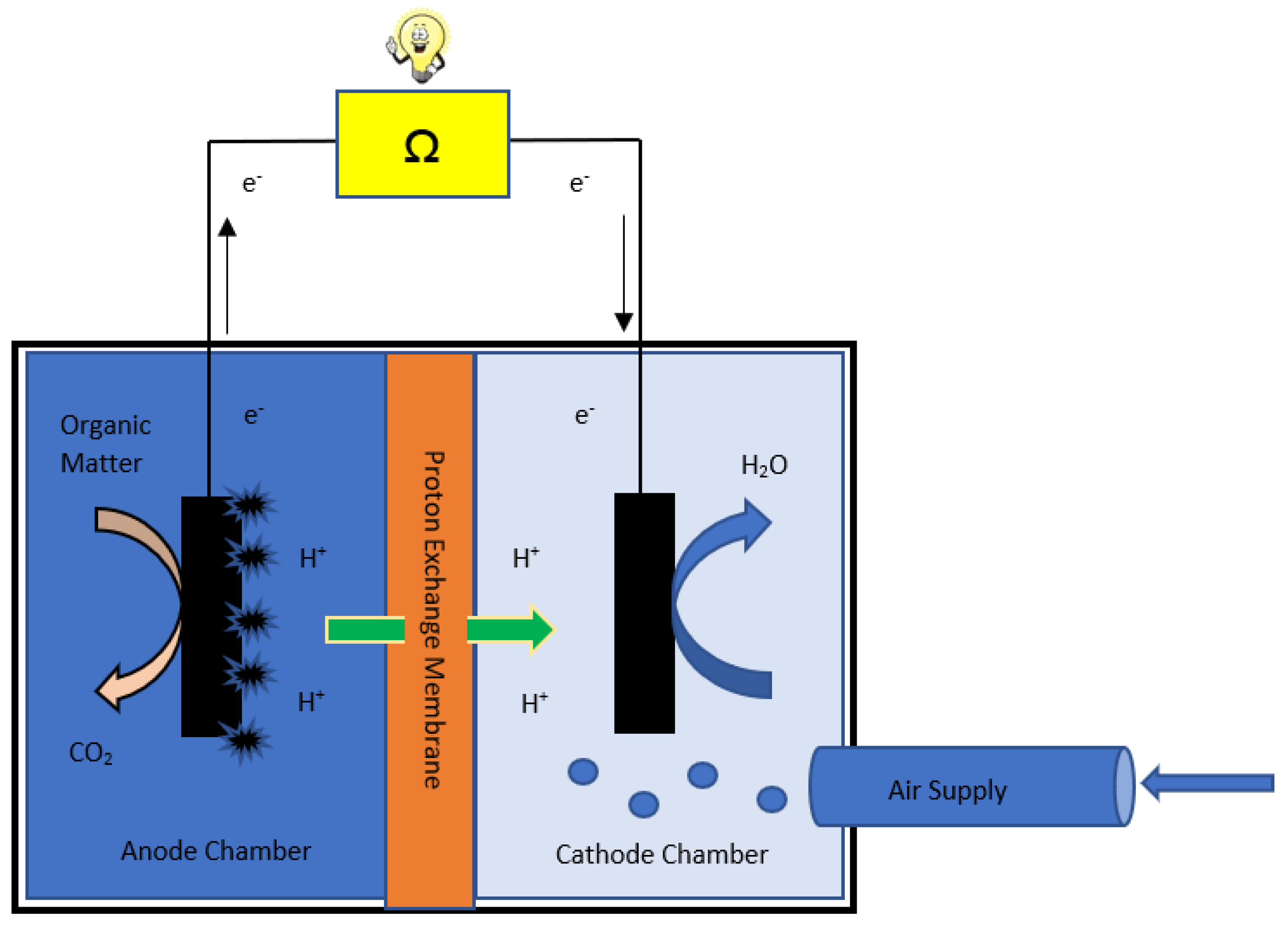
2. Working Principle and Components of MFC

The schematic of MFC is shown in (Figure 1). The wastewater is fed into the anode chamber, where active microbes form a biofilm on the anode surface and microbes oxidize organic matter to produce electrons that are made to flow through an external circuit to reach the cathode. While the protons (H+) move internally through the proton exchange membrane towards the cathode chamber and meet electrons to complete the reaction by producing pure water [20]. The purpose of using a proton exchange membrane in between anodic and cathodic chambers is to allow only the H+ (proton) ions produced in the anodic chamber to pass through towards the cathodic chamber internally [21,22]. Electricity is generated due to the flow of electrons through the external circuit. There are two different reactions at anode and cathode; each has a different reaction rate and kinetics [23]. Each of these components contributes to the device’s performance. Hence, it is crucial to characterize the components to improve the performance of MFC.
Considering glucose as an example substrate [24,25], typical anodic and the cathodic half-reactions are given below [26]:
Anode half-reaction:
C6H12O6 + 6H2O → 6CO2 +24 H+ + 24e
Cathode half reaction:
6O2 + 24e + 24H+ → 12H2O
Complete reaction:
C6H12O6 + 6O2→ 6CO2 + 6H2O
Open circuit voltage generated can be calculated from the Gibbs free energy of water formation and charge of the electrons [27].
ΔE = −ΔG/nF
ΔE = 237,130 (J/mol)/2 × 96,480 (C/mol) = 1.23 Volts
where n is the number of exchanged electrons and F is Faraday’s constant. For the oxidation of hydrogen and water formation, n = 2; Gibbs free energy, ΔG is −237,130 J/mol; F = Faraday’s constant value is 96,480 C/mol [28]. Therefore, for generating energy for useful purposes, a number of cells need to be stacked [22].

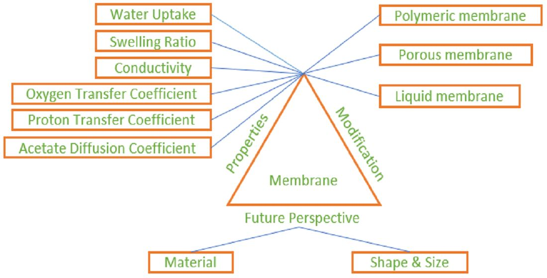
3. Role of Proton Exchange Membrane and Characterization

The performance of an MFC depends on the microbial activity in the anodic chamber and the efficient passage of the protons into the cathodic chamber. In this regard, the membrane acts as a boundary between the anaerobic anode chamber and aerobic cathode and no undesired mixing of species between chambers is allowed [29]. The membrane should also facilitate transportation of only H+ ion from anode to cathode and repel all other anions and negatively charged particles and prevent crossover of O2 from cathodic to the anodic chamber.
Proton exchange membranes are partially permeable and made of ionomers that only conducts protons and restricts electrons. The membrane also does not permit the flow of any gaseous products (i.e., carbon dioxide (CO2) in the anodic chamber and oxygen (O2) in the cathodic chamber) [30]. The most commonly used membrane is Nafion from DuPont, an ionomer with a perfluorinated backbone such as Teflon [26]. Nafion has been widely used in other types of fuel cells and batteries such as polymer electrolyte membrane fuel cells (PEMFC), vanadium redox flow batteries (VRFBs) etc. [31]. The conductive co-polymer Nafion is a sulfonated tetrafluoroethylene-based fluoropolymer [32]. Nafion has a high hydrophobicity due to the presence of perfluoroalkyl backbones. As a cation exchange polymer, Nafion prevents anionic species from reaching the electrode surface while allowing cation to pass through. The hydrophilic Nafion film has a negatively charged sulfonate group that provides selective preconcentration of positively charged particles via electrostatic interaction. In contrast, the hydrophobic fluorocarbon chain gives a selectivity for the hydrophobic part of the molecule [27]. Moreover, Nafion provides good chemical and mechanical stability due to the Polytetrafluoroethylene (PTFE) backbone and strong C-F bonds. The advantage of using Nafion as a membrane in MFC is its excellent proton conductivity due to the significant phase separation between hydrophilic and hydrophobic domains. Other advantages are good antifouling capacity and chemical compatibility [31].
Proton conductivity acts as the fundamental property of membranes when assessing the potential material for membranes, especially for electricity generation applications. Resistive losses are dependent on the proton conductivity and ionic resistance of the membrane. Research work has been done to analyze the effect of the thickness of the membrane on the output performance of MFC. The experiments were done for three different thicknesses 2.5, 5, and 10 mm of the membrane made of fine fire clay material. The maximum absolute power around 2.1 mW was obtained using a 2.5 mm thick membrane since a thinner membrane has lower ionic resistance than the thick one [33]. A research study was carried out to analyze the effect of the thickness of the Nafion membrane used in an iron-chromium redox flow battery with thicknesses of 50, 126, and 178 µm. The maximum utilization of electrolytes was observed with a thickness of 126 µm. The outcome of the research work implies that the thinner membrane has less internal resistance and higher permeability to electro active species [34]. Another research work was carried out to analyze the effect of the thickness of nanocomposite membrane on the output of MFC by using STAT 15 optimization tool. The experiments were carried out using three different thicknesses of the nanocomposite membrane, such as 100, 120, and 140 µm. The maximum power density of around 147 mW/m2 was obtained for the membrane thickness of 120 µm (0.12 mm) [35]. Although the thinnest membrane was 100 µm but this study indicates the need to optimize the thickness of the membrane to minimize the internal resistance, ionic loss and maximize the permeability of electroactive species. At a molecular level, the proton transport in hydrated polymeric matrices is based on two principal mechanisms: proton hopping technique in which protons are transferred from one site to another through the formation [36] and breaking of hydrogen bonds known as Grotthuss-type mechanism and diffusion mechanism where water acts as the vehicle [37,38].
In MFC, the suspended microorganisms make a thin layer on the membrane surface. The formed thin layer may lead to choking of membrane called biofouling and has been observed by some researchers [39]. This fouling affects the flow of protons through the membrane [40]. According to another study, in a continuous flow, MFC may lose nutrients as the substrate present in influent wastewater passes through the membrane. Undesired oxygen diffusion from the cathodic chamber to anode also adversely affects microbial activity. So, considering all of these possibilities that may affect the cell’s performance, proton exchange membranes should exhibit certain characteristics. Understanding these characteristics also lead to modification of membrane design. The techniques to determine the essential properties of the membrane are described briefly below.

3.1. Water Uptake

The water uptake is a property that defines the amount of water retained by a saturated membrane. It is measured by immersing the membrane in demineralized water at 30 °C for 24 h to reach an equilibrium state [41]. The membrane gets swollen after this operation. The weight of the swollen membrane is measured after removing the excess water from the surface of it, and the dry weight of the membrane before it is introduced to deionized water is measured by drying it at 30 °C for 15 h [42,43]. The water uptake capacity is expressed as % and calculated using the following equation.
W a t e r   U p t a k e   c a p a c i t y   ( % ) = ( w t .   o f   s w o l l e n   m e m b r a n e w t .   o f   d r y   m e m b r a n e ) w t .   o f   d r y   m e m b r a n e   × 100
Water uptake capacity is dependent mainly on the functional group of the polymeric membrane. Hydrophilic membranes have more water uptake capacity with a specific functional group such as -SO3H [44]. This property of the proton exchange membrane is sensitive since it is directly connected to the ion exchange capacity. Enhancement in water uptake can directly increase the ion exchange capacity of a particular polymeric membrane. A research study showed that in (VRFB) vanadium redox flow batteries, the maximum ion exchange capacity was obtained around 1.73 meq/g using a pristine SPEEK membrane with the highest water uptake capacity 35.1% compared to the other types [45].

3.2. Swelling Ratio

Polymer membrane starts swelling due to osmosis and absorption in the presence of solution depending on the specific solute concentration [46]. The membrane gets swelled when it comes in contact with deionized water. The thickness of the wet membrane is measured by allowing it to soak in deionized water at 30 °C for 24 h. It is allowed to dry at 30 °C for 15 h for estimating the dry membrane thickness [42]. The difference in the thickness between the swollen membrane and the dried membrane is measured. The swelling ratio is expressed as follows.
S w e l l i n g   r a t i o   ( % ) = ( t h i c k n e s s s   o f   w e t   m e m b r a n e t h i c k n e s s   o f   d r y   m e m b r a n e ) t h i c k n e s s   o f   d r y   m e m b r a n e   × 100
The proton exchange membrane often shrinks and swells depending on the solute concentration of water. The membrane is regenerable and often needs to be regenerated with a dilute solution of strong mineral acids. During regeneration and operation, the membrane swells a lot due to the concentration difference of the aqueous solution. The swelling ratio plays a significant role when the membrane needs regeneration. An increase in the swelling ratio enhances the membrane’s life cycle and partially boosts the hydrophilicity, but excess swelling may adversely affect the mechanical properties. When the membrane swells, the size may become larger, but the thickness decreases. In this way, the membrane may become more porous, leading to gas/oxygen diffusion through the membrane [47].

3.3. Oxygen Transfer Coefficient

The proton exchange membrane restricts oxygen into the anodic chamber. The oxygen transfer coefficient is the property that defines the ability to transfer (diffuse) oxygen through the membrane. In order to measure this coefficient, the cathode chamber is recirculated with oxygen saturated demineralized water under continuous aeration. In contrast, the anodic chamber is kept anaerobic by sparging nitrogen or argon gas [48]. The perturbation in dissolved oxygen (DO) in the anodic chamber is measured by inserting a DO probe. The oxygen mass transfer coefficient and diffusion coefficient are calculated as below [49].
O x y g e n   m a s s   t r a n s f e r   c o e f f i c i e n t   ( K O ,   c m / s ) = V A × t × ln [ ( C 0 C ) / C 0 ]
where V is the volume of liquid in the anaerobic chamber, A is the effective surface area of the membrane, C0 is the saturated oxygen concentration in the cathodic chamber, and C is the concentration of oxygen in the anaerobic anode chamber at a time t.
D i f f u s i o n   c o e f f i c i e n t ( D o   , c m 2 s ) = K O × L t
where, Lt is the thickness of the membrane [50].

3.4. Proton Conductivity

It is an important property of the membrane. Researchers have reported a method to measure a membrane’s conductivity and diffusion coefficient in MFC [51]. They filled two chambers with demineralized water with different proton concentrations C1, C2. Caustic soda lye was used to maintain the pH of chamber one at 10.5 and whereas, chamber two was filled with demineralized water at pH level 6.5. C22 is the proton concentration in chamber two after a certain time interval t. The proton transfer coefficient and diffusion coefficient are calculated as below.
P r o t o n   t r a n s f e r   c o e f f i c i e n t ( K H   c m / s ) = V A × t × ln [ ( C 1 + C 2 2 C 22 ) / ( C 1 C 2 ) ]
D i f f u s i o n   c o e f f i c i e n t ( D H ,   c m 2 s ) = K H × L t
where V is the volume of two identical chambers, A is the effective membrane surface area, and Lt is the membrane thickness.
In most designs, the cathode chamber is always maintained in aerobic condition, and the condition in the anodic chamber is essentially kept anaerobic. Crossover of oxygen from cathodic to anodic chamber slows down the microbial activity in the anodic chamber leading to decrease output. There are many polyvalent cations other than the H+ ion present in the wastewater. Membrane selectively uptake the H+ ions [30] and helps to migrate them from anodic to the cathodic chamber. So, this property of the membrane is important since the selectivity of H+ ions over all other cations plays a significant role in output performance.

3.5. Substrate (Acetate) Diffusion Coefficient

The wastewater contains several organic compounds which are consumed by microbes. In MFC research work, several organic materials are used as a substrate, such as acetate, glucose, lactate etc. Transportation of acetate or substrate from anodic to the cathodic chamber is not desired since it inhibits the output performance [9], often known as substrate loss [52]. A simple experiment can determine the ability of a membrane to transfer the substrate from anode to cathode [53].
A known concentration of acetate is used in demineralized water at the anodic side of the membrane and measured the change in acetate concentration in both chambers after a certain time interval t by using GC (gas chromatography). The Acetate transfer coefficient and diffusion coefficient are calculated as below.
A c e t a t e   t r a n s f e r   c o e f f i c i e n t ( K A   c m / s ) = V A × t × ln [ ( C A 2 C C ) / ( C A ) ]
  D i f f u s i o n   c o e f f i c i e n t ( D A ,   c m 2 s ) = K A × L t
where CA is the concentration of acetate in the anode chamber, CC is the concentration of acetate in the cathode chamber at time t, V is the volume of the chamber, and A is the effective surface area of the membrane.

4. State of the Art and Modification of the Membrane

As mentioned earlier, Nafion is the most used perfluorosulfonic acid (PFSA) membrane in MFCs. Nafion is s sulfonated tetrafluoroethylene-based conductive fluoropolymer. Nafion has a high hydrophobicity due to the presence of perfluoroalkyl backbones. The hydrophilic -SO3H groups are attached to the terminals, located at the end of the side chain. This fix negatively charged sulfonated group (-SO3H) at the terminal ends to enhance the proton conductivity of the membrane. The proton conductivity of Nafion 117 is 2 × 10⁻² (S/cm), and it has an ion exchange capacity of 0.982 meq/gm. The water uptake capacity is around 22% at room temperature [30]. The oxygen transfer coefficient and diffusivity values are Ko = 1.6 × 10⁻⁴ (cm/s) and Do = 5.35 × 10⁻⁶ (cm2/s) respectively [52]. It has been investigated by several researchers that due to the values of oxygen transfer and diffusivity coefficient of Nafion, leakage of oxygen from the cathodic to the anodic chamber occurs. This phenomenon is quite undesired for the anaerobic microorganism in the anodic chamber.
Focusing on developing the efficacies of Nafion, many research works have been carried out based on its critical properties. Enhancement of proton conductivity and ion exchange capacity can directly boost the output of MFC. Minimizing oxygen transfer coefficient and acetate diffusion coefficient is another modification to enhance output. The recent development of Nafion and the use of other materials as a membrane in MFCs are briefly discussed in this section. Minimizing of migration of acetate was also achieved by using a membrane made of clay and activated carbon derived from coconut shells [53]. Several researchers have altered the essential properties of the membrane, either by modifying the Nafion membrane or by developing less expensive alternative and hybrid materials. These developments and modifications are discussed below.

4.1. Use & Modification of Perfluorinated and Non-Fluorinated Polymeric Membranes

Flemion™ and Hyflon® are commercially available Perfluorinated polymeric membranes used in PEM fuel cells [54], and therefore can also be used in MFC. A group of researchers have investigated the performance of Flemion in MFC and achieved 200 mW/m2 output power density [55]. Another research work reported using Hyflon in MFC and obtained around 80 mW/m2 from a stack of four MFC units, which is not very promising [30,56]. Various essential properties of the membrane were modified by several researchers by either adapting the Nafion membrane or developing cheaper alternatives and hybrid materials.
The improvisation of titanium dioxide (TiO2) in sulfonated polyether ether ketone membrane showed better results for ion-exchange properties, proton conductivity, oxygen transfer coefficient, and power densities than pure Nafion 117. The researchers had optimized the concentration of the titanium dioxide to modify the Nafion membrane. The best result was found at the TiO2 concentration of 7.5% [41]. Above 7.5% doping of TiO2 showed a blocking effect and started to hinder the conductivity of the proton through the membrane. Cation exchange membrane exhibits polymeric chain movement due to its long-chain polymeric structure. This movement of long-chain polymers helps to transport protons. Amount of doping more than 7.5% of TiO2 blocked the movement of the long-chain polymers. This phenomenon is called the blocking effect. The homogeneous distribution of TiO2 as an inorganic filler in Nafion makes the membrane more amorphous. An increase in the amorphous structure of the membrane leads to higher porosity than that for pure Nafion. The increase in the porosity leads to a comparably low-pressure drop and fouling across the membrane. Optimum doping of TiO2 in sulfonated polyether ether ketone showed robustness and sustainability in the long-run operation.
Some researchers have tested other inexpensive materials such as sulfonated silicon dioxide (S-SiO2) in sulfonated polystyrene ethylene butylene polystyrene and showed an increase in the output power densities compared to normal Nafion 117 [49]. They used a single-chambered microbial fuel cell in their experiment to measure the concentration dependencies of sulfonated silicon dioxide on output power densities. Based on the doping concentrations (2.5%, 5%, 7.5%, and 10%) the best result was obtained at 7.5% concertation of sulfonated silicon dioxide. The ion exchange capacity, the conductivity of protons, water uptake capacity, were improved, and the substrate loss was reduced. Migration of oxygen from cathode to anode was also minimum at 7.5% concentration. Ionic conductivity increased by three times compared to Nafion 117; proton conductivity increased by 1.6 times; water uptake capacity increased by 9.5 times; and the oxygen transfer coefficient decreased by 4.6 times.
Overall, the output of the test MFC increased by four-fold compared to Nafion 117. Moreover, the researchers reported an 83% decrease in cost compared to Nafion117, available at USD 1500 per 1 m2 area, whereas the cost of (S-SiO2)- (SSEBS) membrane is reported as around USD 250 [49]. The paper also showed the cost comparison of this nano synthesized membrane with Nafion 117 and a scaled-up MFC system of 1000 liter capacity [49].
A group of researchers [57] used graphene oxide (GO) in sulfonated polyether ether ketone (SPEEK) to find an alternative and inexpensive material compared to the Nafion117 membrane for MFC for wastewater treatment application. The modification slightly decreased the water uptake capacity of the membrane. However, hydrophilic oxygenated functional groups accelerated H+ ion transfer through hydrogen bond resulting in high proton conductivity. Although GO SPEEK produced 10% less power density than Nafion 117, the coulombic efficiency of the GO SPEEK membrane was 1.4 times more than that of Nafion. This modified membrane also offered an excellent antifouling property [57]. Therefore, a Modified GO SPEEK membrane can be a good option for wastewater treatment applications in MFC.
Another research group laminated the surface of the Nafion 117 membrane with chlorosulfonic acid to form sulfonated polyvinylidene fluoride (PVdF) [51]. This lamination inhibited the oxygen migration from cathode to anode, resulting in higher open-circuit voltages (OCVs) and coulombic efficiency than Nafion 117. The maximum power density obtained was around 446 mW/m2, and the blending of PVdF slightly increased the cell’s proton conductivity and ion exchange capacity. The modified membrane maintained the much-needed anaerobic conditions in the anode chamber due to the very low oxygen transfer coefficient and diffusivity property.
In another paper, blending of ion exchange material and polybenzimidazole (PBI) with polyvinylpyrrolidone (PVP) was carried out to increase the hygroscopic content of the membrane and increase the performance of the MFC [58]. The blend ratio of (PBI: PVP) was varied from 70:30, 50:50, and 30:70 and dependencies of blend ratio on the power output were evaluated. The 30:70 ratio of (PBI: PVP) showed the best output density of 231 mW/m2, compared with the output of other ratios [58].
Introduction of hygroscopic material such as 5% aluminum oxide (Al2O3) in sulfonated polyvinylidene fluoride (PVdF) copolymerized with hexafluoropropylene (HFP)/Nafion blended membrane electrode assembly improved the output power densities of MFC [46]. The use of Al2O3 made the process more expensive with respect to the achieved output. The addition of fillers such as ferrosoferric oxide (Fe3O4) in polyarylene ether sulfone (PES) membrane can also be another way of improving the performance of MFC. Logan compared the performance of air cathode single-chambered microbial fuel cells in the presence and absence of polymeric membrane. The output power density in the presence of membrane was around 262 mW/m2 whereas, without the proton exchange membrane, it was around 494 mW/m2 [59]. The paper showed a better result in the case of batch operation of MFC. However, in the case of continuous steady-state operation over a period of time, the output needs to be monitored for both conditions to make a decisive conclusion.
Another important study was reported using sulfonated polystyrene-ethylene-butylene-polystyrene (SPSEBS) membrane that achieved 106.9% enhanced output performance than Nafion 117. The maximum output power density obtained was 600 mW/m2. This output was achieved due to the increased water uptake capacity of the SPSEBS membrane and decreased oxygen permeability by one order of magnitude compared to that of Nafion 117 [50].

4.2. Porous Membranes

Many researchers have reported clay and ceramics as potential inexpensive membrane materials. The purpose of using ceramic or clay membrane over cation exchange membrane was to make the system more cost-effective. Some researchers have used ceramic membranes and studied the MFC performance in batch and continuous operation [60]. The comparison was made between three kinds of ceramic membranes, CM1, CM2 and CM3, with porosities of 0.14, 0.015, and 0.0005 microns, respectively. CM3 exhibited a better output power density than the other porosities. This smallest pore size of CM3 helped to block higher valent relatively large cations and allowed only H+ ions to migrate. The highest power densities obtained were 1790 mW/m2 in batch operation and 2300 mW/m2 in continuous operation. Whereas, using Nafion membrane, the power densities were 1225 mW/m2 and 1880 mW/m2 in batch and continuous mode operations, respectively [60].
Nafion 117 membranes are regenerable, but the cost is relatively higher than a one-time usable ceramic membrane. Although the life of ceramic membrane is short, more tests need to be performed over extended periods to compare the true-life cycle cost of ceramic membranes concerning the regenerable Nafion 117 membrane.
Clay consists of various hygroscopic oxides such as titanium dioxide (TiO2), aluminum sulfate (Al2(SO4)3), silicon dioxide (SiO2), aluminum oxide (Al2O3) and aluminum silicate (Al2SiO5). With these hygroscopic components and being cheap, clay is a good candidate as a membrane material. Researchers used activated carbon derived from coconut shells to improve the surface properties of clay membranes [52]. The specific surface area of activated carbon helped in preserving bound water and enhanced proton hopping through the membrane.
The capital expenditure or cost of ACCS/Clay membrane is 45 US Dollars/m2, almost 40 times less than the cost of Nafion 117 [52]. In contrast, the operational expenditure is higher for ACCS/Clay membrane. Moreover, the researchers have reported that clay and activated carbon (ACCS/Clay) membrane produced less power output than Nafion in MFC. In order to compare the life cycle cost between porous and Nafion membrane, more studies need to be conducted focusing on the output performance and operational expenditures.

4.3. Liquid Membranes

A study on the ionic liquid separator (1-octyl-3-methylimidazolium hexafluorophosphate, ([omim] [PF6]) was carried out by some researchers [61], and it was found that it performs well only for thermophilic microorganisms [62]. Another study was carried out by preparing membrane using ionic liquid 1-butyl-3-methylimidazoluim hexafluorophosphate ionic liquid ([bmim] [PF6]) and PVDF polymer, which performed better due to various mass transfer phenomena taking place through the ionic liquid. The ionic liquid is suitable when the operating temperature is more than 50–60 °C, but at a lower temperature, the power density is low at 179 mW/m2. Moreover, [bmim] [PF6] is very expensive, increasing the overall cost of MFC. The research results of these developments are summarized in Table 1.

5. Comparative Analysis of Polymeric Modified Membranes with Nafion

Various studies focusing on cost optimization and development of the polymeric membrane were conducted in the past few years [46,49,50,57]. Examples are doping of polymeric compounds such as polybenzimidazole (PBI), polyvinylpyrrolidone (PVP), polypropylene (PP), polystyrene, sulfonated polyether ether ketone (SPEEK), sulfonated polyvinylidene fluoride (PVdF) with HFP, sulfonated polystyrene ethylene butylene polystyrene (SSEBS), and sulfonated polyether ether ketone (SPEEK) has been broadly studied. Among these materials, sulfonated polyether ether ketone (SPEEK) and sulfonated polystyrene ethylene butylene polystyrene (SSEBS) have proved to be alternative cheap materials to Nafion 117. Modification of Nafion membrane by using TiO2 with a certain concentration gives a promising output but the use of titanium dioxide also makes MFC expensive. The properties of SPEEK, SSEBS, and GO SPEEK membrane as alternative inexpensive materials are compared with Nafion 117 in terms of output performance of MFC and showed in Table 2.

6. Future Perspective

MFC has the ability to convert waste material directly into electricity. Therefore, it has many potential applications such as biosensors, sanitation, wastewater treatment, biohydrogen production etc. [63,64,65,66]. However, most papers are aimed at laboratory scale study in batch [67], fed-batch [68] and continuous mode operation to measure output current and power density by varying materials of the key components of MFC [69,70]. Very few publications focus on application-based development for MFC commercialization [71,72]. Researchers highlighted several barriers to achieving good performance in large scale operations. Primarily, materials and then the proper design of stacking of MFC can minimize ohmic losses and internal resistance of the system [73,74]. Cost is also a big barrier to the commercialization of the technology. Membrane carries almost 60% of the total cost of a typical MFC [30]. To make the membrane more robust and compatible with different wastewater sources, both the shape and selection of material are the important factors.
The surface-to-volume ratio is an essential parameter for efficient ion exchange. An increase in the surface area can directly increase the membrane’s active sites, which enhances the exchange of protons. Therefore, modelling and optimization based on the cost of material need to be carried out with the proper architecture of the overall MFC. For example, in polymeric electrolytic membrane fuel cell, Nafion 211 membrane was used with prism structured by using thermal imprinting technique with TiO2 [75]. The prism shape of the membrane increased the surface area and helped to avoid water clogging, as shown in (Figure 2). Similar attempts can be made to make the prism structured using composite membrane for MFC to investigate its impact on performance compared to the traditional membrane.

7. Conclusions

This paper reviews the state of the art of membrane used in MFC. The essential characteristics that impact the performance and cost of the MFC system are discussed. Currently, polymer-based commercial membranes are used. However, there is a need for alternative materials which are comparatively cheaper than polymer-based membranes without losing functionality. Based on published research results following conclusions can be made.
  • The two most essential membrane characteristics are ion exchange capacity and the mass transfer coefficients for MFC operation. The researchers have made several attempts to find alternative materials compared to expensive Nafion 117. GO/SPEEK and SiO2-S dopped in SSEBS are shown as suitable alternative materials that performed 55% and 107% better than Nafion, respectively.
  • Cheap, porous materials such as clay and ceramic are also potential materials for membranes in MFC. The surface of clay membranes can be modified using activated carbon to improve performance. The modified clay membrane performed better than the clay membrane, but clay membranes were not sustainable.
  • The ceramic membrane is found to be better than Nafion, but it is not reusable. Due to the large porosity, oxygen diffuses into the anode and adversely affects the anaerobic conditions. The substrate also diffuses into the cathode, inhibiting microbial activity.
  • Most published papers show that MFC works fine under controlled laboratory environments using the lab-scale system. But to develop the MFC system for large-scale operations in real applications, several aspects need to be considered. Only then the MFC technology can compete with the existing wastewater treatment and waste to energy technologies.
Finally, it can be concluded that polymer materials have the potential to be used in developing large scale MFC systems. However, more research is required to increase the durability and reduce the cost of materials.

Author Contributions

Conceptualization, A.B. and R.K.C.; methodology, A.B.; validation, A.B. and R.K.C.; formal analysis, A.B.; data curation, A.B.; writing—original draft preparation, A.B. and R.K.C.; writing—review and editing, F.E.E.; supervision, R.K.C. and F.E.E.; project administration, R.K.C. and F.E.E.; funding acquisition, R.K.C. All authors have read and agreed to the published version of the manuscript.

Funding

The work was conducted as PhD research jointly funded by SPRING Eu-India (Agreement No. 821423), and UiT funded the APC.

Institutional Review Board Statement

Not Applicable.

Informed Consent Statement

Not Applicable.

Data Availability Statement

Not Applicable.

Conflicts of Interest

The authors declare that they do not have any competing interest or any kind of personal relationship that could affect the work shown in this review article.

Notation

VVolume of the anodic (1) and cathodic (2) chamber (ml)
AEffective surface area of the membrane (cm2)
C0Saturated oxygen concentration in the cathodic chamber (mg/L)
tTime (h)
KoMass Transfer Coefficient of Oxygen (cm/s)
DoDiffusion Coefficient of Oxygen (cm2/s)
CConcentration of oxygen in the anaerobic anode chamber at a time t (mg/L)
LtThickness of the membrane (cm)
KHProton transfer Coefficient (cm/s)
DHDiffusion Coefficient of proton (cm2/s)
C1concentration of proton (H+) in first chamber (mol/L)
C2concentration of proton (H+) in second chamber (mol/L)
C22concentration of proton (H+) in second chamber at a time interval t (mol/L)
KAAcetate transfer Coefficient (cm/s)
DADiffusion Coefficient of Acetate (cm2/s)
CAConcentration of acetate in anode chamber (mg/L)
CBConcentration of acetate in cathode chamber at a time interval t (mg/L)
ΔGGibbs free energy (J/mol)
FFaraday’s constant (C/mol)

References

  1. Cohen, B. The Bacterial Culture as an Electrical Half-Cell. J. Bacteriol. 1931, 21, 18–19. [Google Scholar]
  2. Perna, A.; Kim, S. Pem Fuel Cells and Vanadium Redox Flow Batteries: Two. In Proceedings of the European Fuel Cell Technology & Applications Conference—Piero Lunghi Conference 2017, Naples, Italy, 12–15 December 2017; pp. 15–17. [Google Scholar]
  3. Zhang, H.; Sun, C. Cost-effective iron-based aqueous redox flow batteries for large-scale energy storage application: A review. J. Power Sources 2021, 493, 229445. [Google Scholar] [CrossRef]
  4. Gangadharan, P.; Nambi, I.M. Hexavalent chromium reduction and energy recovery by using dual-chambered microbial fuel cell. Water Sci. Technol. 2015, 71, 353–358. [Google Scholar] [CrossRef] [Green Version]
  5. Kim, H.J.; Park, H.S.; Hyun, M.S.; Chang, I.S.; Kim, M.; Kim, B.H. A mediator-less microbial fuel cell using a metal reducing bacterium, Shewanella putrefaciens. Enzym. Microb. Technol. 2002, 30, 145–152. [Google Scholar] [CrossRef]
  6. Zhang, H.; Shen, P.K. Recent Development of Polymer Electrolyte Membranes for Fuel Cells. Chem. Rev. 2012, 112, 2780–2832. [Google Scholar] [CrossRef]
  7. Kaewkannetra, P.; Chiwes, W.; Chiu, T.Y. Treatment of cassava mill wastewater and production of electricity through microbial fuel cell technology. Fuel 2011, 90, 2746–2750. [Google Scholar] [CrossRef]
  8. Song, T.-S.; Jin, Y.; Bao, J.; Kang, D.; Xie, J. Graphene/biofilm composites for enhancement of hexavalent chromium reduction and electricity production in a biocathode microbial fuel cell. J. Hazard. Mater. 2016, 317, 73–80. [Google Scholar] [CrossRef] [PubMed]
  9. Abbasi, U.; Jin, W.; Pervez, A.; Bhatti, Z.A.; Tariq, M.; Shaheen, S.; Iqbal, A.; Mahmood, Q. Anaerobic microbial fuel cell treating combined industrial wastewater: Correlation of electricity generation with pollutants. Bioresour. Technol. 2016, 200, 1–7. [Google Scholar] [CrossRef]
  10. Yu, D.; Bai, L.; Zhai, J.; Wang, Y.; Dong, S. Toxicity detection in water containing heavy metal ions with a self-powered microbial fuel cell-based biosensor. Talanta 2017, 168, 210–216. [Google Scholar] [CrossRef]
  11. Mukherjee, S.; Su, S.; Panmanee, W.; Irvin, R.T.; Hassett, D.J.; Choi, S. A microliter-scale microbial fuel cell array for bacterial electrogenic screening. Sens. Actuators A: Phys. 2013, 201, 532–537. [Google Scholar] [CrossRef]
  12. He, Y.-R.; Xiao, X.; Li, W.-W.; Cai, P.-J.; Yuan, S.-J.; Yan, F.-F.; He, M.-X.; Sheng, G.-P.; Tong, Z.-H.; Yu, H.-Q. Electricity generation from dissolved organic matter in polluted lake water using a microbial fuel cell (MFC). Biochem. Eng. J. 2013, 71, 57–61. [Google Scholar] [CrossRef]
  13. Feng, C.; Huang, L.; Yu, H.; Yi, X.; Wei, C. Simultaneous phenol removal, nitrification and denitrification using microbial fuel cell technology. Water Res. 2015, 76, 160–170. [Google Scholar] [CrossRef] [PubMed]
  14. Sevda, S.; Abu-Reesh, I.M.; Yuan, H.; He, Z. Bioelectricity generation from treatment of petroleum refinery wastewater with simultaneous seawater desalination in microbial desalination cells. Energy Convers. Manag. 2017, 141, 101–107. [Google Scholar] [CrossRef]
  15. Mohanakrishna, G.; Venkata Mohan, S.; Sarma, P.N. Bio-electrochemical treatment of distillery wastewater in microbial fuel cell facilitating decolorization and desalination along with power generation. J. Hazard. Mater. 2010, 177, 487–494. [Google Scholar] [CrossRef] [PubMed]
  16. Venkata Mohan, S.; Mohanakrishna, G.; Srikanth, S.; Sarma, P. Harnessing of bioelectricity in microbial fuel cell (MFC) employing aerated cathode through anaerobic treatment of chemical wastewater using selectively enriched hydrogen producing mixed consortia. Fuel 2008, 87, 2667–2676. [Google Scholar] [CrossRef]
  17. Chae, K.-J.; Choi, M.-J.; Kim, K.-Y.; Ajayi, F.; Park, W.; Kim, C.-W.; Kim, I.S. Methanogenesis control by employing various environmental stress conditions in two-chambered microbial fuel cells. Bioresour. Technol. 2010, 101, 5350–5357. [Google Scholar] [CrossRef]
  18. Ezziat, L.; ElAbed, A.; Ibnsouda, S.; El Abed, S.; ElAbed, A. Challenges of Microbial Fuel Cell Architecture on Heavy Metal Recovery and Removal From Wastewater. Front. Energy Res. 2019, 7, 1–13. [Google Scholar] [CrossRef]
  19. Mathuriya, A.S.; Jadhav, D.A.; Ghangrekar, M.M. Architectural adaptations of microbial fuel cells. Appl. Microbiol. Biotechnol. 2018, 102, 9419–9432. [Google Scholar] [CrossRef]
  20. Kalia, V.C.; Kumar, P. Microbial Applications vol. 1 Bioremediation and Bioenergy; Springer: Cham, Switzerland, 2018. [Google Scholar] [CrossRef]
  21. Das, D. Microbial Fuel Cell; Springer International Publishing: Cham, Switzerland, 2018. [Google Scholar]
  22. Flimban, S.G.A.; Ismail, I.M.I.; Kim, T.; Oh, S.-E. Overview of Recent Advancements in the Microbial Fuel Cell from Fundamentals to Applications: Design, Major Elements, and Scalability. Energies 2019, 12, 3390. [Google Scholar] [CrossRef] [Green Version]
  23. Oliveira, V.; Simões, M.; Melo, L.; Pinto, A. Overview on the developments of microbial fuel cells. Biochem. Eng. J. 2013, 73, 53–64. [Google Scholar] [CrossRef]
  24. Gezginci, M.; Uysal, Y. Electricity generation using different substrates and their different concentrations in microbial fuel cell. J. Environ. Prot. Ecol. 2014, 15, 1744–1750. [Google Scholar]
  25. Jafary, T.; Ghoreyshi, A.A.; Najafpour, G.D. The Effect of Substrate Concentration on the Electrical Performance of Microbial Fuel Cell (MFC). In Proceedings of the International Conference on Environment 2010, Penag, Malaysia, 13–15 December 2010. [Google Scholar]
  26. Rahimnejad, M.; Bakeri, G.; Najafpour, G.; Ghasemi, M.; Oh, S.-E. A review on the effect of proton exchange membranes in microbial fuel cells. Biofuel Res. J. 2014, 1, 7–15. [Google Scholar] [CrossRef]
  27. Gautam, D.; Anjum, S.; Ikram, S. Proton Exchange Membrane (PEM) in Fuel Cells: A Review. IUP J. Chem. 2010, III, 51–81. [Google Scholar]
  28. Logan, B.E.; Hamelers, B.; Rozendal, R.; Schröder, U.; Keller, J.; Freguia, S.; Aelterman, P.; Verstraete, W.; Rabaey, K. Microbial Fuel Cells: Methodology and Technology. Environ. Sci. Technol. 2006, 40, 5181–5192. [Google Scholar] [CrossRef]
  29. Dharmalingam, S.; Kugarajah, V.; Sugumar, M. Membranes for Microbial Fuel Cells; Elsevier: Amsterdam, The Netherlands, 2018. [Google Scholar]
  30. Ramirez-nava, J.; Mart, M.; Hern, G. The Implications of Membranes Used as Separators in Microbial Fuel Cells. Membranes 2021, 11, 738. [Google Scholar] [CrossRef] [PubMed]
  31. Sun, C.; Złotorowicz, A.; Nawn, G.; Negro, E.; Bertasi, F.; Pagot, G.; Vezzù, K.; Pace, G.; Guarnieri, M.; Di Noto, V. [Nafion/(WO3)x] hybrid membranes for vanadium redox flow batteries. Solid State Ionics 2018, 319, 110–116. [Google Scholar] [CrossRef]
  32. Mokhtarian, N.; Ghasemi, M.; Daud, W.R.W.; Ismail, M.; Najafpour, G.; Alam, J. Improvement of Microbial Fuel Cell Performance by Using Nafion Polyaniline Composite Membranes as a Separator. J. Fuel Cell Sci. Technol. 2013, 10, 041008. [Google Scholar] [CrossRef]
  33. Merino-Jimenez, I.; Obata, O.; Pasternak, G.; Gajda, I.; Greenman, J.; Ieropoulos, I. Effect of microbial fuel cell operation time on the disinfection efficacy of electrochemically synthesised catholyte from urine. Process. Biochem. 2020, 101, 294–303. [Google Scholar] [CrossRef]
  34. Sun, C.; Zhang, H. Investigation of Nafion series membranes on the performance of iron-chromium redox flow battery. Int. J. Energy Res. 2019. [CrossRef]
  35. Sugumar, M.; Kugarajah, V.; Dharmalingam, S. Optimization of operational factors using statistical design and analysis of nanofiller incorporated polymer electrolyte membrane towards performance enhancement of microbial fuel cell. Process. Saf. Environ. Prot. 2021. [Google Scholar] [CrossRef]
  36. Ghosh, P.; Ramachandran, M.; Kumar, V. Review on Proton Exchange Membranes and its Application in Microbial Fuel Cells. Int. J. Mech. Eng. Technol. 2018, 9, 1632–1641. Available online: http://www.iaeme.com/IJMET/index.asp1632; http://www.iaeme.com/ijmet/issues.asp?JType=IJMET&VType=09&IType=13; http://www.iaeme.com/IJMET/issues; http://www.iaeme.com/IJMET/index.asp1633 (accessed on 21 December 2021).
  37. Breslau, B.R.; Miller, I.F. A hydrodynamic model for electroosmosis. Ind. Eng. Chem. Fundam. 1971, 10, 554–565. [Google Scholar] [CrossRef]
  38. De Grotthuss, C.J.T. Sur la décomposition de l’eau et des corps qu’elle tient en dissolution à l’aide de l’électricité galvanique. Ann. Chim. 1806, 58, 54–73. [Google Scholar]
  39. Miskan, M.; Ismail, M.; Ghasemi, M.; Jahim, J.M.; Nordin, D.; Abu Bakar, M.H. Characterization of membrane biofouling and its effect on the performance of microbial fuel cell. Int. J. Hydrogen Energy 2016, 41, 543–552. [Google Scholar] [CrossRef]
  40. Xu, J.; Sheng, G.-P.; Luo, H.-W.; Li, W.-W.; Wang, L.-F.; Yu, H.-Q. Fouling of proton exchange membrane (PEM) deteriorates the performance of microbial fuel cell. Water Res. 2012, 46, 1817–1824. [Google Scholar] [CrossRef] [PubMed]
  41. Venkatesan, P.N.; Dharmalingam, S. Effect of cation transport of SPEEK—Rutile TiO2 electrolyte on microbial fuel cell performance. J. Membr. Sci. 2015, 492, 518–527. [Google Scholar] [CrossRef]
  42. González-Pabón, M.J.; Figueredo, F.; Martínez-Casillas, D.C.; Cortón, E. Characterization of a new composite membrane for point of need paper-based micro-scale microbial fuel cell analytical devices. PLoS ONE 2019, 14, e0222538. [Google Scholar] [CrossRef]
  43. Tiwari, B.; Noori, T.; Ghangrekar, M. A novel low cost polyvinyl alcohol-Nafion-borosilicate membrane separator for microbial fuel cell. Mater. Chem. Phys. 2016, 182, 86–93. [Google Scholar] [CrossRef]
  44. Dawkhar, S.A.; Attar, S.J.; Rikame, S.S. Fabrication of Cation Exchange Membrane for Microbial Fuel Cells. Int. J. Recent Technol. Eng. 2019, 8, 769–773. [Google Scholar] [CrossRef]
  45. Sun, C.; Negro, E.; Vezzù, K.; Pagot, G.; Cavinato, G.; Nale, A.; Bang, Y.H.; Di Noto, V. Hybrid inorganic-organic proton-conducting membranes based on SPEEK doped with WO3 nanoparticles for application in vanadium redox flow batteries. Electrochim. Acta 2019, 309, 311–325. [Google Scholar] [CrossRef]
  46. Kumar, V.; Kumar, P.; Nandy, A.; Kundu, P.P. A nanocomposite membrane composed of incorporated nano-alumina within sulfonated PVDF-co-HFP/Nafion blend as separating barrier in a single chambered microbial fuel cell. RSC Adv. 2016, 6, 23571–23580. [Google Scholar] [CrossRef]
  47. Zhang, Y.; Ting, J.W.Y.; Rohan, R.; Cai, W.; Li, J.; Xu, G.; Chen, Z.; Lin, A.; Cheng, H. Fabrication of a proton exchange membrane via blended sulfonimide functionalized polyamide. J. Mater. Sci. 2014, 49, 3442–3450. [Google Scholar] [CrossRef] [Green Version]
  48. Tao, H.-C.; Sun, X.-N.; Xiong, Y. A novel hybrid anion exchange membrane for high performance microbial fuel cells. RSC Adv. 2014, 5, 4659–4663. [Google Scholar] [CrossRef]
  49. Sivasankaran, A.; Sangeetha, D.; Ahn, Y.-H. Nanocomposite membranes based on sulfonated polystyrene ethylene butylene polystyrene (SSEBS) and sulfonated SiO2 for microbial fuel cell application. Chem. Eng. J. 2016, 289, 442–451. [Google Scholar] [CrossRef]
  50. Ayyaru, S.; Letchoumanane, P.; Dharmalingam, S.; Stanislaus, A.R. Performance of sulfonated polystyrene–ethylene–butylene–polystyrene membrane in microbial fuel cell for bioelectricity production. J. Power Sources 2012, 217, 204–208. [Google Scholar] [CrossRef]
  51. Kumar, V.; Kumar, P.; Nandy, A.; Kundu, P.P. Fabrication of laminated and coated Nafion 117 membranes for reduced mass transfer in microbial fuel cells. RSC Adv. 2016, 6, 21526–21534. [Google Scholar] [CrossRef]
  52. Chae, K.-J.; Choi, M.; Ajayi, F.F.; Park, W.; Chang, I.S.; Kim, I.S. Mass Transport through a Proton Exchange Membrane (Nafion) in Microbial Fuel Cells. Energy Fuels 2007, 22, 169–176. [Google Scholar] [CrossRef]
  53. Neethu, B.; Bhowmick, G.D.; Ghangrekar, M. A novel proton exchange membrane developed from clay and activated carbon derived from coconut shell for application in microbial fuel cell. Biochem. Eng. J. 2019, 148, 170–177. [Google Scholar] [CrossRef]
  54. Colomban, P. Proton conductors and their applications: A tentative historical overview of the early researches. Solid State Ionics 2019, 334, 125–144. [Google Scholar] [CrossRef]
  55. Scott, K. Membranes and separators for microbial fuel cells. In Microbial Electrochemical and Fuel Cells; Elsevier: Amsterdam, The Netherlands, 2016; pp. 153–178. [Google Scholar] [CrossRef]
  56. Merlo, L.; Ghielmi, A.; Cirillo, L.; Gebert, M.; Arcella, V. Resistance to peroxide degradation of Hyflon® Ion membranes. J. Power Sources 2007, 171, 140–147. [Google Scholar] [CrossRef]
  57. Leong, J.X.; Daud, W.R.W.; Ghasemi, M.; Ahmad, A.; Ismail, M.; Ben Liew, K. Composite membrane containing graphene oxide in sulfonated polyether ether ketone in microbial fuel cell applications. Int. J. Hydrogen Energy 2015, 40, 11604–11614. [Google Scholar] [CrossRef]
  58. Kumar, V.; Mondal, S.; Nandy, A.; Kundu, P.P. Analysis of polybenzimidazole and polyvinylpyrrolidone blend membranes as separating barrier in single chambered microbial fuel cells. Biochem. Eng. J. 2016, 111, 34–42. [Google Scholar] [CrossRef]
  59. Liu, H.; Logan, B. Electricity generation using an air-cathode single chamber microbial fuel cell (MFC) in the absence of a proton exchange membrane. ACS Natl. Meet. B. Abstr. 2004, 228, 4040–4046. [Google Scholar]
  60. Daud, S.M.; Daud, W.R.W.; Kim, B.H.; Somalu, M.R.; Abu Bakar, M.H.; Muchtar, A.; Jahim, J.M.; Lim, S.S.; Chang, I.S. Comparison of performance and ionic concentration gradient of two-chamber microbial fuel cell using ceramic membrane (CM) and cation exchange membrane (CEM) as separators. Electrochim. Acta 2018, 259, 365–376. [Google Scholar] [CrossRef]
  61. Ebrahimi, M.; Kujawski, W.; Fatyeyeva, K.; Kujawa, J. A Review on Ionic Liquids-Based Membranes for Middle and High Temperature Polymer Electrolyte Membrane Fuel Cells (PEM FCs). Int. J. Mol. Sci. 2021, 22, 5430. [Google Scholar] [CrossRef] [PubMed]
  62. Koók, L.; Kaufer, B.; Bakonyi, P.; Rózsenberszki, T.; Rivera, I.; Buitrón, G.; Bélafi-Bakó, K.; Nemestóthy, N. Supported ionic liquid membrane based on [bmim][PF6] can be a promising separator to replace Nafion in microbial fuel cells and improve energy recovery: A comparative process evaluation. J. Membr. Sci. 2019, 570–571, 215–225. [Google Scholar] [CrossRef]
  63. Ivars-Barceló, F.; Zuliani, A.; Fallah, M.; Mashkour, M.; Rahimnejad, M.; Luque, R. Novel Applications of Microbial Fuel Cells in Sensors and Biosensors. Appl. Sci. 2018, 8, 1184. [Google Scholar] [CrossRef] [Green Version]
  64. Jadhav, D.A.; Das, I.; Ghangrekar, M.M.; Pant, D. Moving towards practical applications of microbial fuel cells for sanitation and resource recovery. J. Water Process. Eng. 2020, 38, 101566. [Google Scholar] [CrossRef]
  65. Banu, J.R.; Kavitha, S. Various Sludge Pretreatments: Their Impact on Biogas Generation. In Waste Biomass Management—A Holistic Approach; Springer: Cham, Switzerland, 2017. [Google Scholar] [CrossRef]
  66. Florio, C.; Nastro, R.A.; Flagiello, F.; Minutillo, M.; Pirozzi, D.; Pasquale, V.; Ausiello, A.; Toscano, G.; Jannelli, E.; Dumontet, S. Biohydrogen production from solid phase-microbial fuel cell spent substrate: A preliminary study. J. Clean. Prod. 2019, 227, 506–511. [Google Scholar] [CrossRef]
  67. Sun, Y. Performance Investigation of Batch Mode Microbial Fuel Cells Fed With High Concentration of Glucose. Biomed. J. Sci. Tech. Res. 2018, 3, 001–006. [Google Scholar] [CrossRef]
  68. Pannell, T.C.; Goud, R.K.; Schell, D.; Borole, A. Effect of fed-batch vs. continuous mode of operation on microbial fuel cell performance treating biorefinery wastewater. Biochem. Eng. J. 2016, 116, 85–94. [Google Scholar] [CrossRef] [Green Version]
  69. De Juan, A.; Nixon, B. Technical Evaluation of The Microbial Fuel Cell Technology in Wastewater Applications. J. Sustain. Energy Eng. 2015, 1, 1–18. [Google Scholar] [CrossRef]
  70. Abdallah, M.; Feroz, S.; Alani, S.; Sayed, E.T.; Shanableh, A. Continuous and scalable applications of microbial fuel cells: A critical review. Rev. Environ. Sci. Bio/Technology 2019, 18, 543–578. [Google Scholar] [CrossRef]
  71. Jadhav, D.A.; Mungray, A.K.; Arkatkar, A.; Kumar, S.S. Recent advancement in scaling-up applications of microbial fuel cells: From reality to practicability. Sustain. Energy Technol. Assessments 2021, 45, 101226. [Google Scholar] [CrossRef]
  72. Gajda, I.; Greenman, J.; Ieropoulos, I.A. Recent advancements in real-world microbial fuel cell applications. Curr. Opin. Electrochem. 2018, 11, 78–83. [Google Scholar] [CrossRef]
  73. Fan, Y.; Sharbrough, E.; Liu, H. Quantification of the Internal Resistance Distribution of Microbial Fuel Cells. Environ. Sci. Technol. 2008, 42, 8101–8107. [Google Scholar] [CrossRef]
  74. Logan, B.E.; Zikmund, E.; Yang, W.; Rossi, R.; Kim, K.-Y.; Saikaly, P.E.; Zhang, F. Impact of Ohmic Resistance on Measured Electrode Potentials and Maximum Power Production in Microbial Fuel Cells. Environ. Sci. Technol. 2018, 52, 8977–8985. [Google Scholar] [CrossRef] [PubMed]
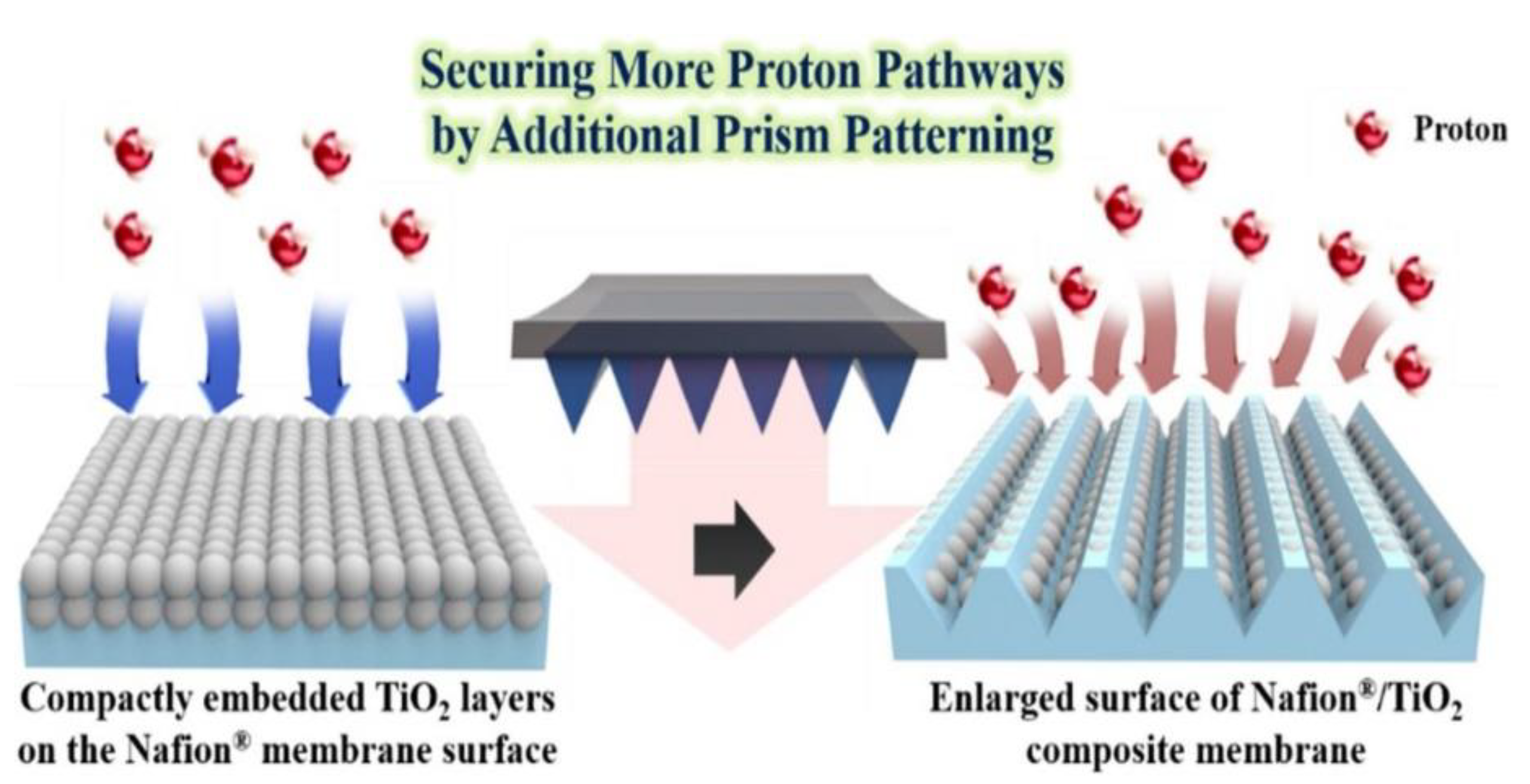
  75. Jang, S.; Kang, Y.S.; Choi, J.; Yeon, J.H.; Seol, C.; Nam, L.V.; Choi, M.; Kim, S.M.; Yoo, S.J. Prism patterned TiO2 layers/Nafion® composite membrane for elevated temperature/low relative humidity fuel cell operation. J. Ind. Eng. Chem. 2020, 90, 327–332. [Google Scholar] [CrossRef]
Figure 1. A schematic diagram of a microbial fuel cell (MFC).
Energies 15 00444 g001
Figure 2. Schematic presentation additional effect of the composite Nafion membrane with prism patterned TiO2 layers [75].
Energies 15 00444 g002
Table 1. Modification of proton exchange membranes and their properties.
Membrane TypeSubstrateMembrane Width (cm)Water Uptake %Proton Conductivity (S/cm)O2 Transfer Coefficient (cm/s)MFC TypePower/Current OutputRef
Nafion and SPEEK in TiO2Glucose0.01821.830.187 × 10−22.2 × 10⁻⁶SCMFC5.7 W/m3[41]
SSEBSAcetate 400.75 × 10⁻⁵-SCMFC1209.7 mW/m2[49]
SPEEK & GO SPEEKAcetate0.02 & 0.02146.69 & 85.360.108 × 10−3
& 0.148 × 10⁻³
1.38 × 10⁻⁶
& 1.15 × 10⁻⁶
Dual chamber812 and 902 mW/m2[57]
Ceramic membrane & Cation exchange membraneAcetate0.25 & 0.018---Dual chamber1790 and 1225 mW/m2[60]
Supported Ionic liquid membrane (SILM)Acetate----Dual Chamber179 mW/m2[62]
Clay and activated carbon-based membrane-derived coconut shellAcetate-19.4-1.3 × 10⁻⁴Dual chamber246 mW/m2[52]
Nafion 117Domestic sludge0.02222 × 10−21.6 × 10⁻⁴SCMFC262 mW/m2[59]
SPSEBSGlucose0.0181640.3820.36 × 10−4SCMFC600 mW/m2[50]
Polybenzimidazole and polyvinylpyrrolidone blended membrane--35.41.2 × 10−3--231.8 mW/m2[58]
Sulfonated PVDF coated Nafion 117Phosphate0.021314.25.91 × 10−39.4 × 10⁻⁵SCMFC446.45 mW/m2[51]
Sulfonated PVDF-co-HFP/Nafion blended with nano aluminaPhosphate0.0224%3.57 × 10−29.27 × 10−4SCMFC541.52 mW/m2[46]
Table 2. Comparison of the properties of the modified membranes SPEEK, SSEBS, and GO SPEEK type with Nafion 117.
CharacteristicsNafion 1177.5% TiO2 Dopped in SPEEK7.5% SiO2-S Dopped in SSEBSGO SPEEKRef
Proton conductivity (S/cm)2 × 1020.187 × 10−23.21 × 10−23.21 × 10−2[41,49,53,57]
Water uptake %2221.8321085.36[41,49,53,57]
Oxygen transfer coefficient, Ko (cm/s)1.6 × 1042.2 × 10−60.75 × 10−51.15 × 10−6[41,49,53,57]
Ion exchange capacity (meq/gm)0.9821.983.01-[41,49,53,57]
Power Density (mW/m2)2905.7 W/m31209902[41,49,53,57]
Publisher’s Note: MDPI stays neutral with regard to jurisdictional claims in published maps and institutional affiliations.

