Article

Heat Storage and Release Performance of Cascade Phase Change Units for Solar Heating in a Severe Cold Region of China

1
School of Energy and Power Engineering, University of Shanghai for Science and Technology, Shanghai 200093, China
2
School of Energy and Environment, Inner Mongolia University of Science and Technology, Baotou 014010, China
3
Department of Mechanical Engineering, Faculty of Engineering and Architecture, Recep Tayyip Erdogan University, Zihni Derin Campus, Rize 53100, Turkey
4
School of Building Services Science and Engineering, Xi’an University of Architecture and Technology, Xi’an 710055, China
*
Authors to whom correspondence should be addressed.
Energies 2022, 15(19), 7421; https://doi.org/10.3390/en15197421
Submission received: 25 August 2022 / Revised: 26 September 2022 / Accepted: 29 September 2022 / Published: 10 October 2022

Abstract

:
The heat storage and release performance of cascade phase change units are investigated numerically for users in Inner Mongolia’s severe cold region. Three schemes of phase change material combinations are thoroughly tested. We obtained a better material combination scheme S3 (palmitic acid + polyethylene glycol), which has higher heat storage capacity per unit mass, higher average heat flux, and better unit synchronisation performance, so that it is more suitable for solar heating and cascade heat storage units in cold regions of Inner Mongolia. This study takes into account the irradiation variation of typical days during the winter heating season. The results show that the palmitic acid and polyethylene glycol combination scheme has the highest total heat storage per unit mass. This scheme also performs well in the synchronisation of two-stage storage units. When compared to the other two schemes, the average heat flux is increased by 25.5% for the first stage unit and 16.8% for the second stage unit.

1. Introduction

Because of its large reserves, cleanliness, and safety, solar energy is regarded as the most promising renewable energy [1,2]. However, it is frequently constrained by intermittent and geographic constraints. The phase change heat storage technique can be used to utilise solar energy efficiently and continuously [3,4].
A heat storage unit is installed in a typical phase change heat storage system, and HTF (heat transfer fluid) flows into and out of the heat storage unit to achieve charging/discharging. However, as heat storage and release progress, the efficiency of a single heat storage unit decreases, affecting heat storage and release efficiency [5]. Furthermore, solar irradiation varies with time, resulting in performance fluctuation when using a traditional single heat storage unit [6]. To address the aforementioned issue, cascade phase change heat storage technology can be designed. This obtained a better material combination scheme S3 (palmitic acid + polyethylene glycol), which has higher heat storage capacity per unit mass, higher average heat flux, and better unit synchronisation performance, so that it is more suitable for solar heating and cascade heat storage units in cold regions of Inner Mongolia.
Wang et al. [7] created a concentric sleeve cascade heat storage system in which the melting point of the phase change material increases sequentially from the inside to the outside. The heat storage time of cascade heat storage was found to be 21% shorter than that of single-stage heat storage. According to Kousksou et al. [8] and Fang et al. [9] using cascaded phase change heat storage can significantly improve heat storage system performance. Gong et al. [10] used multiple phase change materials to conduct thermodynamic analysis of a phase change heat storage system. The findings indicate that using multiple phase change materials for cascade heat storage can improve exergy efficiency over a single unit. The more phase change materials that are used, the greater the exergy improvement. According to the results of Chiu et al. [11] a multi-stage phase change energy storage system can increase heat transfer rate by nearly 40% compared to a single-stage phase change energy storage system.
Hicham El Mghari et al. [12] discovered that the three-stage phase change energy storage system had a 18.4% higher energy storage efficiency than the single-stage phase change energy storage system. K.E. Elfeky, et al. [13] discovered that the three-stage PCMs (phase change materials) unit could improve the heat transfer rate greatly and shorten the heat storage time effectively. Peiro et al. [14] constructed a multi-stage phase change energy storage system and discovered that the temperature of the outlet HTF was more stable. Gong et al. [10] discovered that the cascade phase change thermal storage device achieves the highest exergy efficiency when the phase transition temperature of the thermal storage material is distributed in equal proportions. Adine et al. [15] investigated the effect of HTF inlet condition on the thermal performance of a cascaded phase change thermal storage device and discovered the optimal inlet temperature and mass flow rate. Tamme et al. [16] investigated the melting characteristics of cascaded phase change thermal storage. They discovered that the geometrical relationship between the ambient temperature and the heat source temperature is the phase change temperature in a single-stage thermal storage device. Wang et al. [17] investigated the cascade phase change structure experimentally, and the results revealed that the melting time was reduced by 37% to 42% when compared to the single unit. The advantages of the shell-and-tube cascade storage structure were experimentally validated by Michels and Pitz-Paal et al. [18] they discovered that the cascade storage structure charges and discharges at a faster rate than the single-stage structure.
The modelling of cascade phase change is also in the centre of interest over the last two decades. Hicham El Mghari et al. [12] examined the charging mechanism efficiency and heat transfer characteristics of a three-stage cascaded latent heat thermal energy storage unit (LHTES) with longitudinal fins. To maximise the thermal efficiency of cascade storage units, they optimised the HTF’s inlet temperature and mass flow rate. Domanski et al. [19] investigated the charging and discharging processes of a two-stage phase change heat storage device. The results showed that the first-stage unit’s melting point temperature should be as close to the HTF’s inlet temperature as possible, while the second-stage unit’s melting point temperature should be close to the ambient temperature. Gokon et al. [20] proposed a numerical method for solar thermal storage utilising cascade storage units. In both the charging and discharging processes, they discovered that the cascade design has a higher proportion of liquid phase than the single design, indicating that the cascade structure improves heat transfer. The results showed that the melting point temperature of the first-stage unit should be as close to the inlet temperature of the HTF as possible, while the melting point temperature of the second-stage unit should be close to the ambient temperature. Gokon et al. [20] proposed a numerical method for solar thermal storage with cascade storage units. They discovered that the cascade design has a higher proportion of liquid phase than the single design in both the charging and discharging processes, indicating that the cascade structure improves heat transfer. Fang et al. [9] used the enthalpy method to develop a physical and mathematical model of a cascade storage device with two-stage shell-and-tube units. They did analyses on new different mass components of the PCM affect storage efficiency.
Solar energy density is higher in northwest than southeast in China (as shown in Figure 1) [21]. Inner Mongolia has an abundance of solar energy resources, with total solar radiation ranging from 6490 to 6992 MJ/m2 per year. In the winter, however, there is a long heating period and significant heating demand. As a result, Inner Mongolia appears to be a promising candidate for solar heating development. However, there have been few reports on cascade phase change heat storage technology being used for heating in Inner Mongolia. In this paper, a numerical method is used to investigate the heat storage and release performances of cascade heat storage units with various PCM schemes, as well as to find the best PCM scheme for cascade heat storage in Inner Mongolia’s harsh cold region.
In this paper, the second paragraph introduces the establishment of the model, including the solar radiation in Inner Mongolia, material combination, mathematical model, etc. In the third section, the results are analysed and compared with the experimental results to verify the correctness of the results. The fourth paragraph clarifies the research results.

2. Modelling

2.1. Solar Irradiation Data

Baotou is located in North China, the southern end of the Mongolian Plateau, and the central part of Inner Mongolia. Baotou has a semi-arid continental monsoon climate in the middle temperate zone. The scenery here is pleasant and the temperature is moderate. The annual average temperature is 7.2 °C, the annual average wind speed is 1.2 m/s, the annual total precipitation is 421.8 mm, and the annual sunshine hours are 2882.2 h.
Baotou is located in the severe cold region with intense solar irradiation. It has cold and long winters with a heating period of up to 180 days. The variation of solar irradiation is depicted in Figure 2. This paper studied the solar irradiation on a typical day, 1 January.
Without taking into account the energy lost during heat transfer between the solar collector and the HTF, the hourly solar irradiation energy can be calculated as follows [23]:
Q = 3.6 c t G
where, Q   is the solar radiation energy, kW. G   is the design flow rate, t/h. c is the specific heat capacity of HTF, 2.36 kJ·(kg·K)−1. t is the HTF inlet temperature, K. Considering that the temperature of the heating water supply is generally 348 K, this paper sets the inlet temperature of the HTF to 348 K. To realise the variation of hourly solar irradiation, the flow rate of HTF therefore correspondingly varies, as shown in Figure 3.

2.2. Materials Combination Schemes

The selection and combination of PCM for cascade storage units follows the following rules:
(1)
The phase change temperature of the selected materials should be lower than the inlet temperature of the HTF. The phase change temperature of the material in the first stage unit should be higher than that in the second stage unit;
(2)
A gradient is formed by the phase change temperature difference of the specified material combinations;
(3)
The chosen materials should be common PCM in solar thermal utilisation systems and meet the most basic principles of phase change material screening, such as meeting thermal storage parameter requirements, good economy, environmental protection, and so on.
The materials combination schemes are shown in Table 1.

2.3. Physical and Mathematical Model

This paper investigates a two-stage cascade phase change heat storage device with a shell and tube structure. The heating oil is used as the HTF flowing inside the tube, while the PCM is filled outside. A copper tube with a length of 600 mm and a diameter of 40 mm is used.
As shown in Figure 4, two-stage storage units are separated by 200 mm. Simplifications and assumptions for modelling are as follows:
(1)
The shell and tube’s wall thickness is ignored, and the shell wall is adiabatic;
(2)
The PCMs are homogeneous and uniformly distributed in the storage unit;
(3)
The thermal properties of PCMs are constant.
The mathematical models are described as follows:
The Solidification/Melting model in fluent software is adopted in this article, The simulation software adopts enthalpy porosity method to process the phase change interface and simulate the phase change process. In this method, the paste area is regarded as a porous medium, and the porosity is analogised to the liquid rate. When the porosity of the numerical simulation unit is zero, it is completely solidified, and the unit speed is not considered.
(1)
Mathematical model of HTF and model assumptions
The following assumptions give unsteady three-dimensional flow models of heat transfer during the melting process of PCM in the cylindrical exchanger enclosure:
  • The HTF flow and the liquid PCM are in the laminar pattern;
  • The average temperature of inlet corresponds to the HTF inlet value;
  • Term of viscous dissipation has been neglected, thus the viscous incompressible flow and the temperature distribution in the annulus are described by Navier-Stokes and thermal energy equations, respectively;
  • The density is calculated using the Boussinesq approximation;
  • During the transition from the solid to the liquid state, density remains constant;
  • Since the term of viscous dissipation has been ignored, Navier–Stokes is used to explain the viscous incompressible flow and thermal energy equations is used to explain temperature distribution in the annulus.
The expression for the energy equation of the HTF is:
ρ f c f T f τ + ρ f c f ϑ x T f x + ρ f c f ϑ y T f x = k f 2 T f x 2 + 2 T f y 2
where ρf is the density of the HTF, kg·m−3; cf is the specific heat of the HTF, J·(kg·K)−1; Tf is the temperature of the HTF, K; vx and vy are the flow velocity of HTF in x and y direction, m/s; and kf is the thermal conductivity of the HTF, W·(m·K)−1.
The expression of the momentum equation for the HTF is:
ρ f ϑ x τ + ρ f ϑ x 2 x + ρ f ϑ x ϑ y y = μ f 2 x x 2 + μ f 2 x y 2 P x
ρ f ϑ y τ + ρ f ϑ y 2 y + ρ f ϑ x ϑ y x = μ f 2 y x 2 + μ f 2 y y 2 P y
where μ f is the dynamic viscosity of the HTF, kg·(m·s)−1.
The expression for the continuity equation of the HTF is:
ϑ x x + ϑ y y = 0
(2)
Mathematical model of phase change material
The energy equation expression of the phase change material in the heat storage unit is:
ρ H τ = λ T p
where H = h + h l h s , H = h r + T r T p C p d T p , h l h s = β L , ρ   is the density of the phase change material, kg·m−3; λ   is the thermal conductivity of the phase change material, W·(m·K)−1; T p , T r   are the temperature and reference temperature of the phase change material, respectively, K; H , h , h l , h s , h r   are the enthalpy of the phase change material, respectively, sensible heat specific enthalpy, liquid specific enthalpy, solid specific enthalpy and reference enthalpy, kJ·kg−1; C p is the constant pressure specific heat capacity of the phase change material, kJ·(kg·K)−1; β is the liquid phase ratio; L is the latent heat of the phase change material, kJ·kg−1.
The liquid phase rate in the cascade phase change heat storage unit is calculated as follows:
β = 0                                             T p < T s     T p T s T l T s                             T s < T p < T l 1                                                   T l < T p  
where T s , T l are the solidification temperature and melting temperature of the phase change material, K, respectively.

2.4. Boundary and Initial Conditions

(1)
Boundary conditions
HTF inlet boundary condition:
T f x = 0 , t = T i n l e t  
where Tinlet is the inlet temperature of the HTF, K.
ϑ i n , x x = 0 , t = ϑ i n l e t
ϑ i n , x x = 0 , t = 0  
where ϑ i n , x , ϑ i n , y is the velocity of the HTF in the tube in the x and y directions, m·s−1; is the inlet flow velocity of the HTF, m·s−1.
The boundary conditions on the outer wall of the outer tube is:
T y y = 0 = 0
(2)
Initial conditions
The initial conditions of the cascade phase change heat storage unit is:
T i n x , y , t = 0 = T 0
where   T i n is the temperature of the cascaded phase change heat storage unit and the internal temperature of the HTF, K; T 0 is the initial temperature, K.
The initial temperature inside the cascaded phase change heat storage units is set at 293 K. The inlet flow rate is given in Table 2.

2.5. Numerical Simulation Method

A typical turbulence model and a solidification/melting model were used in the simulation. The SIMPLE approach was employed to link the pressure and velocity fields. The second-order upwind differential method was used in energy and momentum equations. The default relaxation factor has been selected.

3. Results and Analysis

3.1. Model Validation

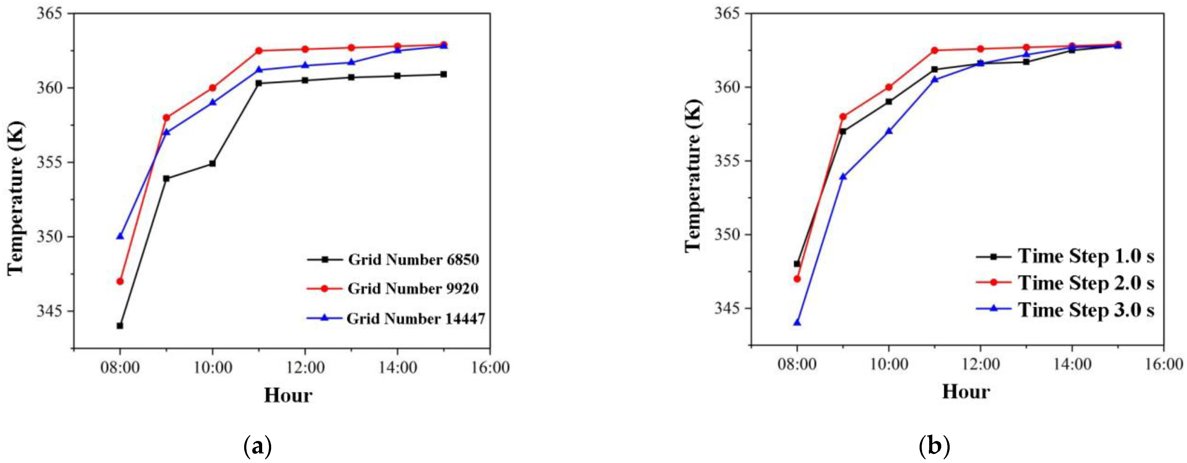
3.1.1. Independence Verification

To adapt to the cylindrical heat storage unit, a rectangular grid is used. For the case of S1, grids of 6850, 9920, and 14,447 were created. Figure 5a depicts the HTF temperature of the cascade storage unit’s outlet at various grid numbers. This study chose grid number 9920 for further computation based on calculation accuracy and computational time. Figure 5b depicts the HTF temperature of the cascade storage unit’s outlet over time. The time step is set to 2.0 s to achieve the effect of accounting for simulation accuracy and simulation efficiency.

3.1.2. Comparison and Verification with Experimental Results

Experimental results with stearic acid as the first stage material and lauric acid as the second stage material were used to validate the model.
Temperature testing was performed 15 mm away from the entrance in a horizontal direction and 30 mm below the inner tube. Figure 6 depicts a comparison of experimental and numerical results. They agree well with the maximum error of 6.9 percent, demonstrating the effectiveness of this modelling.

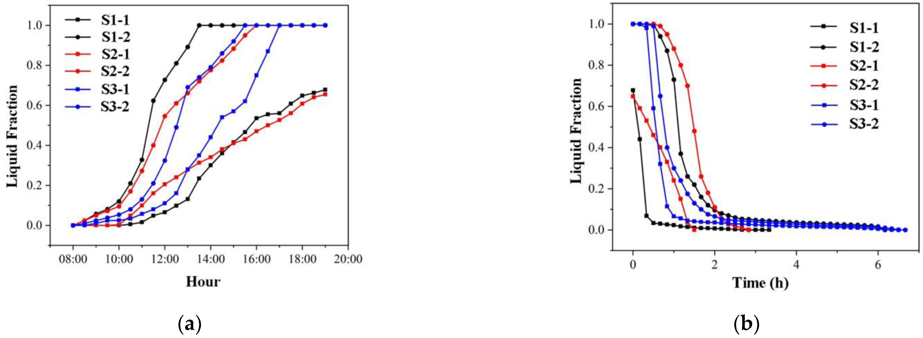
3.2. Heat Storage and Release Performance of Cascade Units

Figure 7 depicts the heat storage behaviours in cascade units with three PCM combination schemes. Similarly, as solar irradiation increases, the PCMs in second stage units melt first. The second stage units in S2 and S3 complete the melting process at 16:00, while S1 finishes 2 h earlier. Only PCM in S3 completes the melting process in the first stage units.
Figure 8a shows the liquid fraction in each heat storage and release unit. The liquid fractions in S3’s two-stage units are closer together than in S1 and S2. As a result, the two units in S3 are more synchronous in the heat storage process, indicating that the temperature gradient setting in S3 is more suitable for the cases studied in this paper. Figure 8b illustrates the liquid fractions in each unit of the heat release process. S3’s two-stage units are more synchronised.
Figure 9 shows the average heat fluxes in the S1–S3 cascade unit. They decrease before 10 a.m. because sensible heat storage by PCM occurs when solar irradiation input is low in the morning. The average heat fluxes in the cascade units of S1–S3 are increasing in the short term due to the rapid increase in solar irradiation from 10 a.m. to 12 p.m. They then drop again because the second stage storage units absorb a lot of heat to help with the phase change. Most cascade units experience latent heat storage between 12 and 4 p.m. After 4 p.m., the sun’s irradiation gradually decreased, while heat fluxes decreased continuously. In heat storage processes S1–S3, the average heat flux is 727.6 W/m2, 781.5 W/m2, and 913.1 W/m2, respectively. Figure 9b depicts the average heat fluxes in the heat release process. They must be constantly dropping when discharging heat. They do, however, drop faster at first due to the release of latent heat. In the heat release process of S1–S3, the average heat flux is 661.1 W/m2, 975.6 W/m2, and 807.2 W/m2, respectively.

4. Conclusions

In this paper, a two-stage cascade heat storage device is investigated for solar heating in the severe cold region of Inner Mongolia. The materials combination schemes, e.g., S1(stearic acid + lauric acid), S2 (paraffin C28 + paraffin C26), and S3 (palmitic acid + polyethylene glycol), were designed for cascade storage units. The heat storage and release performances of each unit were numerically studied. The materials combination scheme S3 (palmitic acid + polyethylene glycol) has higher heat storage capacity per unit mass, higher average heat flux, and better performance of unit synchronisation, making it more suitable for solar heating with cascade heat storage units in the severe cold region of Inner Mongolia. The findings can realise efficient and sustainable utilisation of solar energy and promote social development.

Author Contributions

Conceptualization, L.Z. and S.G.; methodology, J.J. and S.G.; software, Z.L. and L.Z.; validation, Z.L. and L.Z.; formal analysis and investigation, L.Z., Z.L. and G.J.; writing—original draft preparation, L.Z. and Z.L.; writing—review and editing, E.C., J.J. and S.G; supervision, J.J. and S.G.; project administration, S.G.; funding acquisition, S.G. All authors have read and agreed to the published version of the manuscript.

Funding

This research was funded by [National Natural Science Foundation of China] grant number [51966015, 51706111].

Data Availability Statement

Not applicable.

Acknowledgments

We appreciate Yan Liu for his support of experimental validation.

Conflicts of Interest

The authors declare no conflict of interest.

References

  1. Jradi, M.; Veje, C.; Jorgensen, B.N. Performance analysis of a soil-based thermal energy storage system using solar-driven air-source heat pump for Danish buildings sector. Appl. Therm. Eng. 2017, 114, 360–373. [Google Scholar] [CrossRef]
  2. Herche, W. Solar energy strategies in the U.S. utility market. Renew. Sustain. Energy Rev. 2017, 77, 590–595. [Google Scholar] [CrossRef]
  3. Huang, M.; He, W.; Incecik, A.; Gupta, M.K.; Królczyk, G.; Li, Z. Phase change material heat storage performance in the solar thermal storage structure employing experimental evaluation. J. Energy Storage 2022, 46, 103638. [Google Scholar] [CrossRef]
  4. Zhu, C.; Li, B.; Yan, S.; Luo, Q.; Li, C. Experimental research on solar phase change heat storage evaporative heat pump system. Energy Convers. Manag. 2021, 229, 113683. [Google Scholar] [CrossRef]
  5. Lin, W.; Ling, Z.; Fang, X.; Zhang, Z. Experimental and numerical research on thermal performance of a novel thermal energy storage unit with phase change material. Appl. Therm. Eng. 2021, 186, 116493. [Google Scholar] [CrossRef]
  6. Singh, P.; Sharma, R.; Ansu, A.; Goyal, R.; Sarı, A.; Tyagi, V. A comprehensive review on development of eutectic organic phase change materials and their composites for low and medium range thermal energy storage applications. Sol. Energy Mater. Sol. Cells 2021, 223, 110955. [Google Scholar] [CrossRef]
  7. Wang, J.; Ouyang, Y.; Chen, G. Experimental study on charging processes of a cylindrical heat storage capsule employing multiple-phase-change materials. Int. J. Energy Res. 2001, 25, 439–447. [Google Scholar] [CrossRef]
  8. Kousksou, T.; Strub, F.; Lasvignottes, J.C.; Jamil, A.; Bédécarrats, J.P. Second law analysis of latent thermal storage for solar system. Sol. Energy Mater. Sol. Cells 2007, 91, 1275–1281. [Google Scholar] [CrossRef]
  9. Fang, M.; Chen, G.M. Effects of different multiple pcms on the performance of a latent thermal energy storage system. Appl. Therm. Eng. 2006, 27, 994–1000. [Google Scholar] [CrossRef]
  10. Gong, Z.X.; Mujumdar, A.S. Thermodynamic optimization of the thermal process in energy storage using multiple phase change materials. Appl. Therm. Eng. 1997, 17, 1067–1083. [Google Scholar] [CrossRef]
  11. Chiu, J.; Martin, V. Multistage latent heat cold thermal energy storage design analysis. Appl. Energy 2013, 112, 1438–1445. [Google Scholar] [CrossRef]
  12. El Mghari, H.; Idrissi, A.; El Amraoui, R. Cascaded latent heat thermal energy storage device with longitudinal fins: Numerical investigation of melting process and thermal performance analysis. J. Energy Storage 2022, 53, 105199. [Google Scholar] [CrossRef]
  13. Elfeky, K.E.; Ahmed, N.; Wang, Q. Numerical comparison between single PCM and multi-stage PCM based high temperature thermal energy storage for CSP tower plants. Appl. Therm. Eng. 2018, 139, 609–622. [Google Scholar] [CrossRef]
  14. Peiró, G.; Gasia, J.; Miró, L.; Cabeza, L.F. Experimental evaluation at pilot plant scale of multiple PCMs (cascaded) vs. single PCM configuration for thermal energy storage. Renew. Energy 2015, 83, 729–736. [Google Scholar] [CrossRef] [Green Version]
  15. Adine, H.A.; El Qarnia, H. Numerical analysis of the thermal behaviour of a shell and tube heat storage unit using phase change materials. Appl. Math. Model. 2008, 33, 2132–2144. [Google Scholar] [CrossRef]
  16. Tamme, R.; Taut, U.; Streuber, C.; Kalfa, H. Energy storage development for solar thermal processes. Sol. Energy Mater. 1991, 24, 386–396. [Google Scholar] [CrossRef]
  17. Steinmann, W.; Tamme, R. Latent heat storage for solar steam systems. J. Sol. Energy Eng. 2008, 130, 1004–1005. [Google Scholar] [CrossRef]
  18. Michels, H.; Pitz-Paal, R. Cascaded latent heat storage for parabolic trough solar power plants. Sol. Energy 2007, 81, 829–837. [Google Scholar] [CrossRef]
  19. Domanski, R.; Fellah, G. Exergy analysis for the evaluation of a thermal storage system employing PCMS with different melting temperatures. Appl. Therm. Eng. 1996, 16, 907–919. [Google Scholar] [CrossRef]
  20. Gokon, N.; Nakano, D.; Inuta, S.; Kodama, T. High-temperature carbonate/MgO composite materials as thermal storage media for double-walled solar reformer tubes. Sol. Energy 2008, 82, 1145–1153. [Google Scholar] [CrossRef]
  21. SolarGIS. Available online: https://solargis.com/maps-and-gis-data/download/China (accessed on 6 November 2018).
  22. The Meteorological Information Center of the China Meteorological Administration also Has the Meteorological Data Room. Special Meteorological Data Set for Building Environment Analysis in China; China Construction Industry Press: Beijing, China, 2005. [Google Scholar]
  23. Liu, Q.; Bai, Z.; Sun, J.; Yan, Y.; Gao, Z.; Jin, H. Thermodynamics investigation of a solar power system integrated oil and molten salt as heat transfer fluids. Appl. Therm. Eng. 2016, 93, 967–977. [Google Scholar] [CrossRef]
Figure 1. Distribution of solar resources in China [21].
Energies 15 07421 g001
Figure 2. The monthly variation of solar irradiation in Baotou of Inner Mongolia [22].
Energies 15 07421 g002
Figure 3. The hourly solar irradiance intensity and inlet velocity.
Energies 15 07421 g003
Figure 4. Physical model and 2D simplified model of the cascaded phase change heat storage: (a) Physical model; (b) 2D model.
Energies 15 07421 g004aEnergies 15 07421 g004b
Figure 5. Independence analysis of grid number and time step: (a) with different grid numbers; (b) with different time steps.
Energies 15 07421 g005
Figure 6. Comparison of experimental and simulation results.
Energies 15 07421 g006
Figure 7. Heat storage behaviours in cascade units with three combination schemes of PCMs: (a) S1: stearic acid + lauric acid; (b) S2: paraffin (C28) + paraffin (C16); (c) S3: palmitic acid + polyethylene glycol.
Energies 15 07421 g007aEnergies 15 07421 g007b
Figure 8. Liquid fraction in the cascade units of S1–S3: (a) heat storage process; (b) heat release process.
Energies 15 07421 g008
Figure 9. Average heat flux in the cascade units of S1–S3: (a) heat storage process; (b) heat release process.
Energies 15 07421 g009
Table 1. Combination schemes of PCM for cascade storage units.
Scheme 1S1S2S3
MaterialStearic AcidLauric AcidParaffin (C28)Paraffin (C16)Palmitic AcidPolyethyle-ne Glycol
Density/kg·m−39138677807769891200
Specific Heat/J·(kg·K)−1217523002120250024802300
Thermal Conductivity/W·(m·K)−10.2160.1470.1510.1180.1600.190
Latent Heat/kJ·kg−1201.8173.8253.0141.9222.0181.4
Phase Change Temperature/K341318334320332324
Table 2. Hourly solar radiation intensity and inlet velocity fitting values.
 Time8:009:0010:0011:0012:0013:00
Total Radiation Intensity on Horizontal Plane/W·m−221.622.2147.2283.3369.4419.4
Inlet velocity/m s−10.0230.0230.1540.2970.3870.440
 Time14:0015:0016:0017:0018:00--
Total Radiation Intensity on Horizontal Plane/W·m−2419.4380.6297.2158.322.2--
Inlet velocity/m s−10.4400.3990.3160.1660.023--
Publisher’s Note: MDPI stays neutral with regard to jurisdictional claims in published maps and institutional affiliations.

