Article

Salt Deposits and Brine Blowout: Development of a Cross-Linking Composition for Blocking Formations and Methodology for Its Testing

1
Arctic Competence Center, Saint Petersburg Mining University, 199106 Saint Petersburg, Russia
2
Institut für Bohrtechnik und Fluidbergbau, TU Bergakademie Freiberg, D-09599 Freiberg, Germany
3
Center for Technological Development of the Fuel and Energy Complex, Ufa State Petroleum Technological University, 450062 Ufa, Russia
*
Authors to whom correspondence should be addressed.
Energies 2022, 15(19), 7415; https://doi.org/10.3390/en15197415
Submission received: 14 September 2022 / Revised: 29 September 2022 / Accepted: 8 October 2022 / Published: 9 October 2022

Abstract

:
Uncontrolled inflow of formation fluid (brine) into a well adversely affects the cation–anion bonds in solutions and leads to their dissociation and loss of aggregative stability. Blow-out significantly complicates the drilling process and leads to an increase in non-productive time and in financial costs for problem solving. It is necessary to create a blocking screen that allows separation of the layer from the well and prevents brine flow. This article is devoted to the development of polymeric-blocking compositions that work due to the crystallization reaction of divalent salts of calcium and magnesium chlorides. More than 14 components were detected in the formation fluid on the atomic emission spectrometer. Based on the study of the compatibility of components with brine and the study of rheology and filtration processes through a real core under HPHT conditions, the optimal component polymer composition was selected. The reason for the increase in the rheology of composition during its thickening was established. With the help of tomographic studies, the depth of penetration of the filtrate into the core of layers was determined. For further studies, an experimental stand was designed for physical simulation of the isolation process under HPHT conditions and backpressure from the formation.

1. Introduction

The drilling of exploration and production wells at a number of fields in the world and Russia, in particular in Eastern Siberia, is complicated by the presence of brine blowout and absorbing horizons.
Abnormally high pressures of high salinity formations (AHFP) with alternating absorption intervals do not allow accident-free drilling of wells. Often, in such objects with AHFP, the reservoir pressure value greatly exceeds the reservoir pressure gradient corresponding to the section of deposits in conditions of salt deposits and is almost always comparable to the rock pressure value [1]. Drilling of objects with AHFP is timed to the opening of formations saturated with highly mineralized reservoir fluid. In addition to this, there is the problem of penetrating unknown intersalt formations with an anomaly coefficient from 2.35 to 2.65 [1]. As a result, the drilling process is complicated by frequent stops and overflows of highly mineralized formation water (brine), which necessitates the organization of additional measures for its utilization and preservation of environmental safety [2].
The cost of eliminating complications and carrying out repair and isolation works averages from $ 200,000 to $ 400,000 per well, and for gas wells, they range from 2.5% of the total cost of gas production [3]. If all the wells in the field are taken into account, the costs become huge.
The choice of technology for the elimination of brine blowout depends on the genesis of brine and the characteristics of its occurrence in the chemogenic reservoir rock [4]. Therefore, consideration of the issue of the genesis of both brines and their host rocks is an important task.
Brine blowout horizons occur in carbonate reservoirs in the salt column. They are characterized by fractured and fractured-vein types of anomalous hydraulically conductive reservoirs. In addition, a characteristic feature is the interbedding of carbonate and halite rocks and the pseudostratal distribution of the anomalous reservoir in the salt column, caused by the ability to limit the development of cracks along the vertical [5,6]. Due to the hydrodynamic closeness of the reservoirs, the fluid pressure is close to the mountain pressures, as a result of which AHFP zones are formed, which are characteristic of the vast majority of brine manifestations [7].
Brine is a multiphase system formed by an intercrystalline pore solution, soluble salts of halite, calcium sulfate, magnesium, and calcium chlorides, and highly dispersed clay particles [5]. In other words, this is highly mineralized reservoir water with rare metals and mineral salts. As a result of its impact on the well, there is a flowing and deformation of casing strings due to high formation pressures, sticking of drill pipes due to salt plugs, an aggressive effect on casing strings and cement, high flow rates, as well as hydraulic fracturing of overlying weak open formations [8,9].
In the process of washing out the brine along the wellbore to the surface, the salts contained in it crystallize and settle on the walls of the well, thereby narrowing its wellbore and forming salt sludge plugs that clog the formation [10,11].
The crystallization process is initiated by divalent calcium and magnesium cations, which cause coagulation of the drilling fluid, and the landslide precipitation of salt begins, often leading to the abandonment of the well. Under the influence of brine and often accompanying hydrogen sulfide and carbon dioxide, there is rapid corrosion of pipes and cement stone due to brine [12].
To resist the loss of drilling mud and formation fluids blowout, various methods of isolating the wellbore are used, not counting the running of the casing string and its cementing. In the drilling industry, wellbore strengthening is divided into preventive methods and remedial methods. Based on foreign drilling experience, preventive methods of strengthening the wellbore are more effective than restorative ones, but are not always feasible due to the complexity of forecasting in conditions of heterogeneous mining and geological conditions [13]. Restorative techniques are applied to seal the fracture or pore space and isolate the wellhead by applying various loss circulation materials (LCM) [14].
Moreover, to resist brine blowout, methods such as increasing the density of the mud and discharging the brine-producing horizon are sometimes used [10]. During the reopening of the formation, as a result of its blockage by sedimentary brine, the flow rates increase significantly and an increase in density leads only to absorption [15]. In addition, with an increase in the density of the solution, the likelihood of sticking increases. The elimination of complications by discharging the brine-producing horizon is also ineffective since the layers with brine are not completely depleted due to low reservoir properties. By the time the brine blowout is completed, the drilling fluid becomes completely unusable [16]. Moreover, even after the long development of the reservoir, the pressure in it is higher than the underlying horizon. This method is effective only for lenticular local accumulation of brine with low energy [10].
Other methods are also known for isolating brine-producing and absorbing layers. For example, the use of polymer gel systems, which are divided into immature and mature systems [17]. Pre-formed (mature) systems cannot pass interpore channels or natural fractures with a transverse dimension of less than 0.052 mm. Treatment with such gels is mainly used in large artificial cracks that can provide the required depth of gel penetration [18]. The use of immature gel systems is of great interest in this study.
Foamed gels for the isolation of layers have been developed, which are created in the same way as water-based foam systems. However, there are no studies on the application of such systems for HPHT conditions [17].
In industry, there is also the use of selective isolation methods. For example, one can single out the technology for installing a column of expandable pipes [19]. The technology has been quite successfully applied in a number of fields. However, in their study, the authors focused on developing a method of isolation without stopping the drilling process and changing the bottom hole assembly to other specialized equipment, which leads to an increase in well construction time.
On the example of field experience, some successful cases of elimination of brine manifestations were analyzed in a number of fields. At the Znamenskoye field, hydrogels with stabilized nonionic polysaccharides were used [20]. At the Astrakhan gas condensate field, an overpressure method was used followed by the installation of a cement bridge [21]. In the fields of the Eastern Ciscaucasia, a method of relieving pressure and replacing the drilling fluid with a lime-bitumen solution was used [16]. In China, in the Zhongyuan oil field, combined polymer systems based on organic, inorganic crosslinkers, and polyacrylamide were used. The composition was successful at a temperature of 90 °C and a salinity of 0.15 kg/L [22]. All these methods are applicable to specific mining–geological and thermobaric conditions of the deposit. However, based on the production experience of drilling wells at the Kovyktinskoye gas condensate field, all existing and previously used methods for combating brine manifestations turned out to be ineffective [6]. For example, the installation of a cement bridge plug is not effective in salt deposits. The integrity of the cement stone is broken in the process of hardening and constant influx of highly mineralized reservoir fluid. There is no high-quality adhesion of cement to salt rock at the point of contact.
Mining–geological and thermobaric conditions at the deposits are different. A striking example of brine manifestations is the Kovyktinskoye gas condensate field, which is unique in terms of reserves [23]. Well-drilling conditions are among the most aggressive and difficult. Therefore, in this study, when developing a system of crosslinkers, the authors relied precisely on the difficult conditions of the Kovyktinskoye gas condensate field. After all, solving the problem will allow wells to be successfully drilled in the selected field.
Three structural complexes are conventionally distinguished in the field section [24]: suprasalt, saline, and subsalt (consists of sulfate–carbonate and terrigenous subcomplexes). These cavernous and fractured sulfate–carbonate interlayers are reservoirs of extremely saturated and highly mineralized calcium chloride brines. The sulfate–carbonate subcomplex of the presalt complex is characterized by dolomites with metamorphosed calcium chloride brines of high salinity, 0.35–0.4 kg/L on average [25]. Due to the ingress of formation waters from subsalt deposits into the mud, the solubility of the sodium chloride decreases and the salt particles crystallize. Due to the increase in brine inflow, the acidity of the solution increases, and an increase in the impact on polymers leads to a deterioration in the rheological properties of the drilling mud. Therefore, when choosing the component composition of washing liquids, the main emphasis is on nonionic salt-resistant materials [25].
The above points summarize the main motivations of the authors which led to the purpose of this study. To reduce the risks of emergencies during the preparation of the wellbore before running casing strings with further cementing, it is necessary to develop and implement a technology for isolating brine-bearing formations. The solution of the set scientific and technical problem will reduce the time of well construction and reduce the consumption of reagents, as well as ensure industrial and environmental safety of work.

2. Materials and Methods

In the course of this study, methods are used to determine the chemical composition of liquids [26,27]. Methods modernized by the authors are also used, which are based on standard research methods [28] of filtration properties on HPHT filter presses.

2.1. Experimental Methodology

The study was designed to test blocking compositions in conditions as close as possible to the conditions of a real field without the involvement of additional material costs for conducting industrial tests as part of the study.

2.2. Study of Formation Fluid Samples from Developing Intervals

Brine samples were analyzed in the laboratories of Saint Petersburg Mining University on an atomic emission spectrometer ICPE-9000 from Shimadzu.

2.3. Study of the Compatibility of Drilling Fluids and Brine and Brine and Polymer Components of Blocking Compositions

Drilling fluids used by drilling and service companies for drilling brine-producing intervals in the field where the corresponding samples were taken were analyzed. The study was carried out according to the methods provided in the sources [29,30]. The rheological characteristics of drilling fluids were measured after settling the mixture with the addition of brine at various concentrations. For studies under normal conditions and HPHT conditions, a Fann-35SA viscometer and an OFITE 1100 rheometer were used.
Further, the structural and rheological characteristics of brine were studied depending on the concentration of polymer components. The content of polymer components varied in the concentration range from 1% to 10%. The rheological characteristics were determined using a Fann-35SA viscometer. According to the test results, the most suitable polymer components are selected for the next stages of the study.

2.4. Filtration Study of Blocking Compounds

The improved cell design of the OFITE HPHT dynamic filter press was used to determine the curing capacity of polymer-based blocking compounds (Figure 1).
The filtration cell and the procedure for conducting the experiment were modernized in order to maximally approach the geological conditions of the field. An artificial bulk model was created by crushing a part of the salt core taken from the top of developing layers in the same interval where samples of highly mineralized formation fluid were taken on a Fritsch pulverisette 1 (model 2) jaw crusher.
The selection of the blocking composition and its further studies were carried out according to the following methodology.
For the experiment, an OFITE HTHP filter press with a 500 mL chamber was used. A bulk model of crushed core in a volume of 250 cm3 was placed on the bottom of the filtration cell and compacted with a press. A perforated stainless steel disk pre-made according to the inner diameter was installed on the compacted salt layer. Then, the resulting bulk model was saturated with a sample of highly mineralized formation fluid at a pressure drop of 0.1 MPa.
Blocking compositions were prepared in advance in a volume of 300 mL. The liquid glass phase with various silicate modules was diluted with process water and mixed with an IKA laboratory stirrer. Polymers of various concentrations were added to the prepared liquid glass of a given density with a concentration step of 0.5%. The compositions were mixed at a speed of 400–600 rpm for 45–60 min until complete dissolution [18].
The hardener composition is poured into the prepared cell on top of the separating disc and, under a certain pressure, the composition is pumped through an artificially created bulk model saturated with brine until the liquid flow out from the opposite edge completely stops or a constant filtration is established for 150 min.
Filtration studies are carried out both at room temperature of about 22 °C and a pressure of 0.7 MPa, and under thermobaric conditions of the field where our brine and core samples were taken.
Photographs of the bulk model before and after the filtration study were taken at 100× magnification using a Keyence VHX-600 Digital Microscope.

3. Results

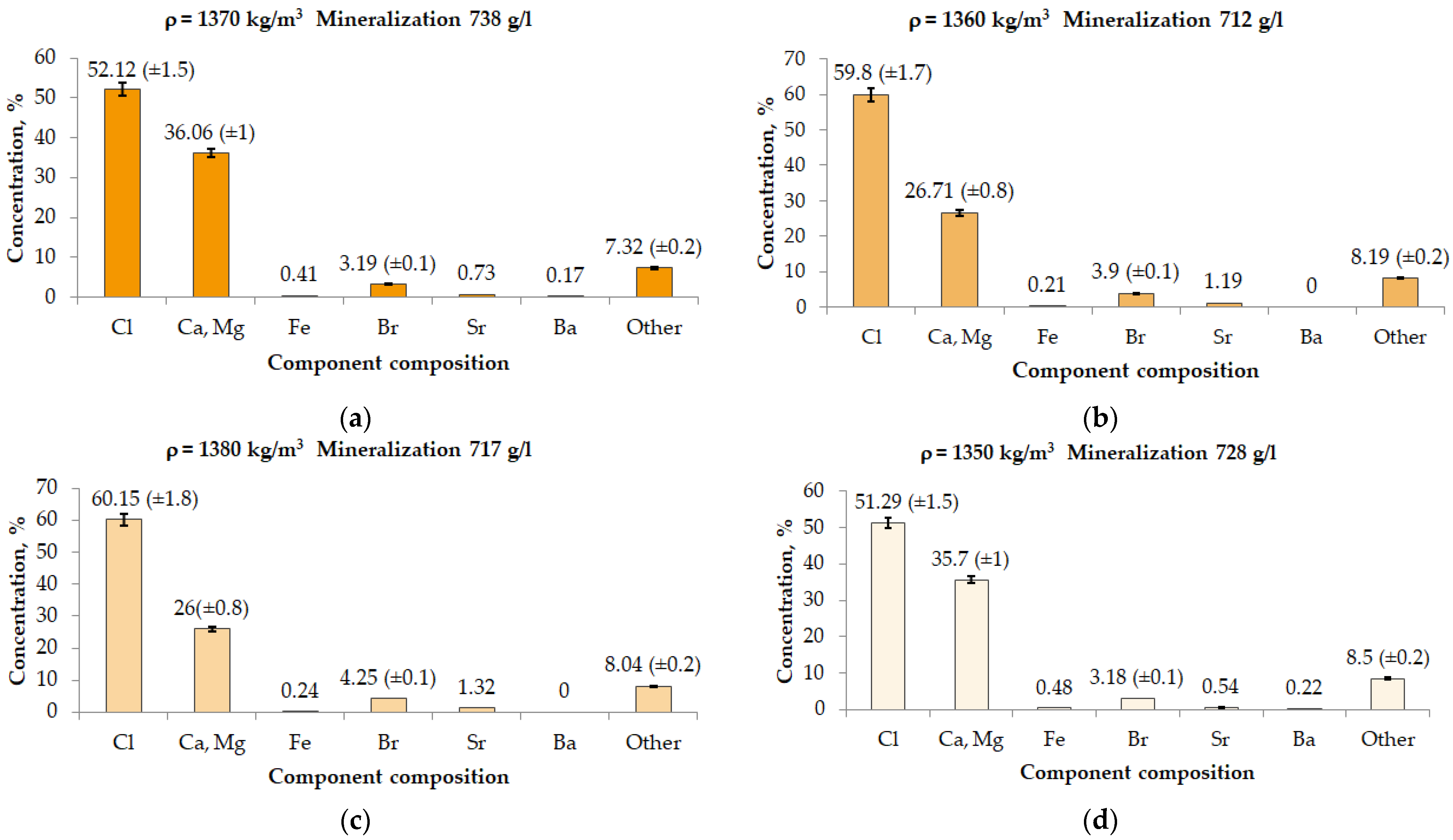
3.1. Chemical Analysis of the Component Composition of Formation Fluid

Determination of the dry residue of the reservoir fluid sample was carried out by comparison with standard solutions with known concentrations of the element being determined by the method of calibration graph and the method of standard additions [26,27].
To carry out measurements, the atomic emission spectrometer was put into operation in accordance with the operating instructions, and the method parameters necessary for the determination of lithium were set. The radiation intensity was measured using the spectral line of lithium at a wavelength of 670.78 nm [26,27]. Standard solutions were sequentially introduced into the atomic steam generator; deionized water was used as a blank, which was used to dilute the brine samples and standard solutions. Measurements of the values of the emission signals of standard solutions were carried out in the mode of three repetitions. The calibration curve was a linear dependence of the concentration of standard solutions on the average emission values with a correlation coefficient r = 0.9998. Measurement of the values of the emission signals of the prepared brine samples was also carried out in the mode of three repetitions, after which the software calculated the values of the lithium concentration automatically according to the constructed calibration graph. The standard deviation of three parallel measurements for each solution did not exceed 3% (reflected in Figure 2). The obtained values were multiplied by the dilution factor.
The result of the study using the calibration graph method is shown in Figure 2.
Based on the results of the formation fluid study, it can be concluded that most of the brine is represented by calcium and magnesium salts. The concentration of chlorides varies from 51.29% to 60.15% and the concentration of calcium and magnesium from 26% to 35.7%.
To confirm the obtained values and eliminate the possible influence of matrix effects, the concentrations of the components in the studied brine samples were also measured using the standard additions method.
As in the previous case, after the atomic emission spectrometer entered the mode and the experimental parameters were set, the values of the emission signals of the studied solutions were measured in the triple repetition mode.
The results of the analysis by the method of standard additions are presented in Table 1.
Based on the results of the study of the component composition of the formation fluid (brine), it can be concluded that most of the brine is represented by divalent salts of calcium from 99,400 to 166,000 mg/dm3 and magnesium from 33,000 to 77,600 mg/dm3. For this reason, the choice of the polymer component for the future blocking composition is directed towards high-quality highly purified polymers. The total mineralization of brine is extremely high and ranges from 717 to 738 g/L.
The brine also contains a rather high concentration of critical metals such as lithium (from 645 to 760 mg/dm3).
Having found out that the highest content of metal cations and salts in the reservoir fluid is predominant, we can assume a further mechanism for blocking brine-saturated reservoirs.
Mainly reaction between CaCl2 and MgCl2 with Na2SiO3 leads to crystallization which results in the formation of insoluble salts (calcium and magnesium silicates):
CaCl 2 + Na 2 SiO 3 H 2 O CaCl 2 + 2 NaCl
This reaction of the formation of a thick gel and insoluble salts will be taken as the basis for further studies.

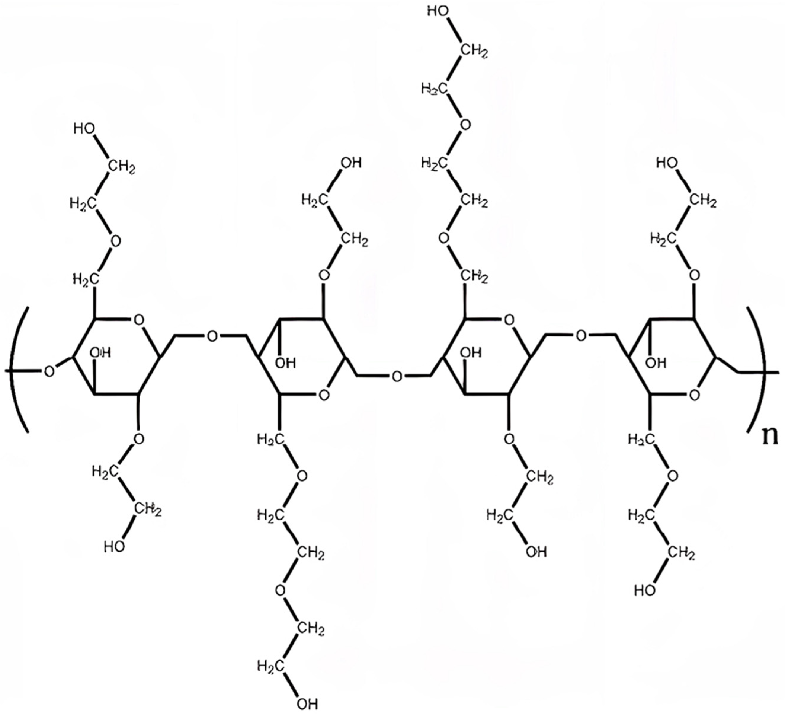
3.2. Selection of a Polymer Base for a Blocking Compound

But the rate of the thickening reaction is too fast. An increase in the viscosity of the liquid glass solution by the additional introduction of a polymer is necessary to reduce the thickening time with brine.
The following materials are used as samples of polymer materials:
  • Xanthan gum (glamine or equivalent) [31,32];
  • Highly purified, high viscosity polyanionic cellulose (Aqua PAC R or equivalent);
  • Copolymer of polyacrylamide and sulfonic acid (polymer x20 or equivalent) [33];
  • Highly purified hydroxyethyl cellulose (HEC) (Natrosol 250 HHR or equivalent) [34].
The polymers based on polyacrylamides (polymer X20) did not dissolve in the brine, although they are salt-resistant materials. There is an understandable reason for this, which is as follows: most often, polymeric materials are dissolved in fresh water, and then inorganic salts are added to fresh solutions [35]. In fresh water, initially, the polymer macromolecule is in an unfolded state, which consumes a large amount of dissolution energy, after which the salinization of the aqueous solution reduces the rheological characteristics, but it does not exfoliate [36].
In the case of brine, it initially contains ions of monovalent and divalent metal ions, which do not allow polyacrylamide molecules to dissolve in the brine [37].
Polysaccharide materials based on polyanionic cellulose and starch, although dissolved, showed no significant changes in the structural and rheological parameters of the brine.
Polymers based on xanthan gum BioSin and HEC Natrosol 250 HHR led to a change in the structural and rheological characteristics of the brine. The measurement results are shown in Table 2.
From the measurement results (Table 2), it can be seen that the polymer based on HEC is most compatible with the brine due to the more flexible macromolecule and the nonionic nature of the functional groups: -CH2OCH2CH2OH and -HC-OCH2CH2OH in HEC.
Therefore, for further research, Natrosol 250 HHR and BioSin biopolymer were chosen as a polymer base for blocking composition.
The results of the study of the structural and rheological characteristics of brine depending on the concentration of polymers are shown in Table 3.
From the analysis of the data obtained, it can be seen that satisfactory rheological properties can be observed in a number of compositions based on Natrosol 250 HHR. The performance based on the Biosin polymer is unsatisfactory due to low values of dynamic shear stress (DSS).
Rheological properties at angles of twist from 3 to 600 degrees change smoothly in compositions based on Natrosol 250 HHR at a concentration of 1% to 3%. At 5% and 7% polymer, the value is too high and reaches 60 and 230, respectively.
The index of plastic viscosity of the solution of the composition based on Natrosol 250 HHR is optimal at a concentration of 1% to 3% and varies from 12 to 14 mPa·s. At the same time, at a polymer concentration of 5% and 7%, the value of plastic viscosity already increases by 28 mPa·s and 30 mPa·s, respectively, which is an unsatisfactory value.
The obtained values of dynamic shear stress are optimal only for the composition based on Natrosol 250 HHR at a concentration of 3% and 5% and are 15 and 20 dPa. At a concentration of 1% and 2%, the DSS value is too low and amounts to 5 dPa, and at a polymer concentration of 7%, the DSS value is too high—146 dPa.
Based on the analysis of structural and rheological characteristics, an additive based on Natrosol 250 HHR at a concentration of 3% will further be considered the optimal polymer for compatibility with brine.
For maximum approximation of the conditions of the field, we will determine the structural and rheological characteristics of the compositions under the thermobaric conditions of the field. The studies were carried out on the OFITE 1100 rheometer.
The results are presented in Table 4.
To explain the results, let us discuss the physicochemical properties of polymers and their chemical structure.
The physicochemical properties of polymers and their solutions depend on their primary chemical structural formula. Most often, the main reason for the increase in the viscosity of polymer solutions is the intermolecular interaction of macromolecules with each other. If the properties of dilute polymer solutions do not increase critically, then with a growth in the polymer concentration, a rapid and significant rise in the structural and rheological properties of their solutions occurs [38].
The mechanism of a rapid and significant rise in the rheological characteristics of a HEC solution is determined by its chemical structure of the primary structural link shown in Figure 3.
Like most branched polysaccharides, HEC is capable of forming highly viscous solutions at low concentrations. During dispersion in water, the pendant hydroxyethyl and dihydroxyethyl groups attached to the cellulose core interact via hydrogen bonds with water molecules. Because of this, HEC molecules are intermolecularly intertwined in the aqueous phase, which in turn leads to an increase in viscosity and gelation. With a further increase in the concentration of HEC, an increase in viscosity and gelation occurs, in this case, water molecules form an ordered structure around the HEC molecule and thereby lead to a multiple increase in structural and rheological characteristics [38].
In the practice of oil and gas well construction, rheological parameters included in the Bingham–Shvedov equation are most widely used: limiting dynamic shear stress, plastic viscosity, and structural characteristics are estimated from static shear stress for 10 min and 10 s. The optimal ratio is [38]:
DSS PV 1 ÷ 1.5   ( performed   only   when   calculating   in   units   of   the   API   Standard )
In our case, this ratio is achieved at an additive polymer (HEC) concentration of 3%.
At the same time, based on the analysis of the values in Table 3 and Table 4, it can be concluded that changing the thermobaric testing conditions does not significantly affect the rheological characteristics of the mixture of polymers and brine.

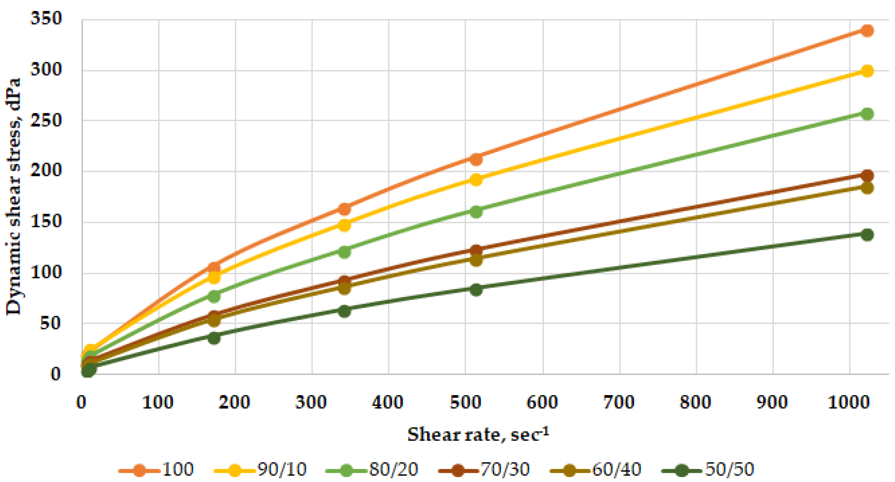
3.3. Studies of the Influence of Brine on the Structural–Rheological and Filtration Characteristics of Drilling Fluids

Since the drilling of rape-bearing horizons involves the opening of reservoirs with AHFP, when drilling this interval, it is rational to use, for example, a weighted polymer-clay drilling fluid [39].
The studies include the addition of formation fluid (brine) to a weighted drilling fluid with a density of 2050 kg/m3 [40].
A salt-saturated drilling fluid based on sodium chloride with a density of 1180 kg/m3 was used as a dispersed medium in the weighted mud. The use of a salt-saturated drilling fluid is associated with preventing the erosion of the salt strata and the formation of possible caverns [41,42].
The weighting of the drilling fluid was carried out with barite concentrate and the regulation of filtration and rheological parameters with the help of the following materials: biopolymer Glamin—structure-forming agent; resin polymer—stabilizer of rheological and filtration properties; FHLS—lignosulfonate thinner; Polideform—defoamer; and Polyeconol A—crystallization inhibitor [43,44].
To study the compatibility of the drilling fluid with brine, six mixtures were considered. The first composition (100) was clean drilling fluid. Then, we gradually diluted the drilling fluid with brine in increments of 10% of the total volume of the mixture. The final sixth composition (50/50) was a mixture containing 50% drilling fluid and 50% brine.
The resulting mixture rheological profiles are shown in Figure 4.
The compatibility test was repeated after warming up for 8 h at 60 °C. The resulting rheological profiles are shown in Figure 5.
Based on the nature of the rheological curves and the data obtained, it can be concluded that the weighted polymer-clay drilling fluid is combined with the reservoir fluid. The addition of brine to the weighted solution does not lead to its thickening. This is observed on the graph with rheological profiles—the values of the dynamic shear stress decrease as the solution is diluted with brine.

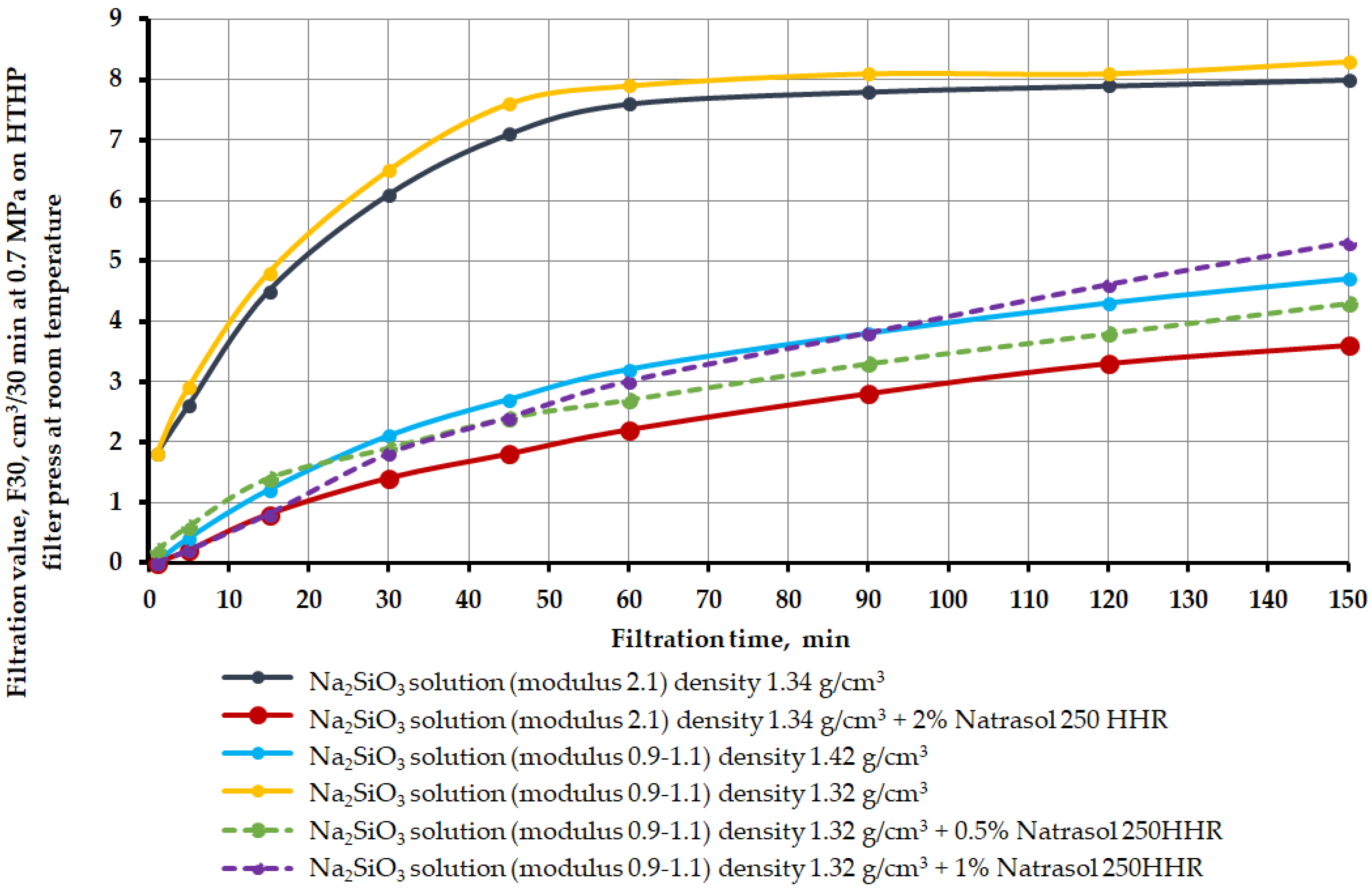
3.4. The Study of the Filtration Characteristics of the Blocking Composition under Normal Conditions

The previously prepared blocking composition was poured into the cell and pumped until the liquid outflow from the opposite edge completely stopped or until a constant filtration was established for 150 min at a pressure drop of 0.7 MPa.
As part of the experiment, seven blocking compositions without polymer and with the addition of a polymer were investigated. The change in filtration values can be seen in Figure 6. The core samples used for the fill model and the fill model after the experiment are shown in Figure 7.
Description of the results: Na2SiO3 solution (module 2.1) density 1420 kg/m3—the formed filtrate passed through the entire bulk model, displacing the brine. The filtrate acquired a blue-gray precipitate. When pressed, it did not collapse and did not crumble. Na2SiO3 solution (module 2.1), density 1340 kg/m3—the formed filtrate passed through the entire bulk model, displacing the brine. The filtrate acquired a blue-gray precipitate. When pressed, it did not collapse and did not crumble. Na2SiO3 solution (module 2.1) density 1340 kg/m3 + 2% Natrosol 250 HHR—unformed filtrate did not pass through the entire bulk model. A hard crust formed on the top of the sample. Na2SiO3 solution (modulus 0.9–1.1), density 1420 kg/m3—the formed filtrate passed through the entire bulk model, displacing the brine. When pressed, it collapsed and did not crumble—fragile. Na2SiO3 solution (modulus 0.9–1.1) density 1320 kg/m3—the formed filtrate passed through the entire bulk model. When pressed, it collapsed and crumbled—fragile. Na2SiO3 solution (modulus 0.9–1.1) density 1320 kg/m3 + 0.5% Natrosol 250 HHR—the formed filtrate passed through the entire bulk model. When pressed, it collapsed and crumbled—fragile. Na2SiO3 solution (modulus 0.9–1.1) density 1320 kg/m3 + 1% Natrosol 250 HHR—formed filtrate passed through the entire bulk model. When pressed, it collapsed and crumbled—fragile.
From the test results obtained, the following conclusions can be drawn for this section:
The use of only liquid glass with a silicate module 2.1 quickly seizes a salt sample saturated with brine in a short period of time, which makes its use not very convenient from a technological point of view. That is, this composition has too fast gel time.
A dilute solution of liquid glass with a modulus of 2.1 and a density of 1340 kg/m3 passes through the entire bulk model. The whole sample is not destroyed.
A liquid glass solution with a density of 1320 kg/m3 passed through the entire sample. The sample is solid, but destroyed.
All sodium silicate solutions with a silicate modulus of 0.9–1.1 were destroyed when removed from the filter-press cell.
To provide a more even water glass distribution front through the bulk model, the water glass solution was treated with Natrosol 250 HHR HEC at concentrations from 0.5% to 2%. The strongest sample was formed when processing up to 2% of the polymer.
According to the results of the studies, the optimal composition for blocking brine-bearing formations is a composition based on a solution of liquid glass (density 1340 kg/m3) with a silicate module 2.1, additionally treated with Natrosol 250 HHR HEC at a concentration of 2%.
To check the effectiveness of the use of the blocking composition, filtration studies were also carried out on carbonate core samples.
The result of applying a blocking composition based on Na2SiO3 with a silicate modulus 3.4 with a density of 1250 kg/m3 treated with hydroxyethyl cellulose at a concentration of 2% is shown in Figure 8.
Based on the visual inspection of the bulk model after the experiment (Figure 8), it can be concluded that the composition based on liquid glass with silicate 3.4 with a density of 1250 kg/m3, treated with HEC at a concentration of 2%, effectively binds grains of carbonate core pre-saturated with brine. A strong structure is formed that does not crumble into small particles.

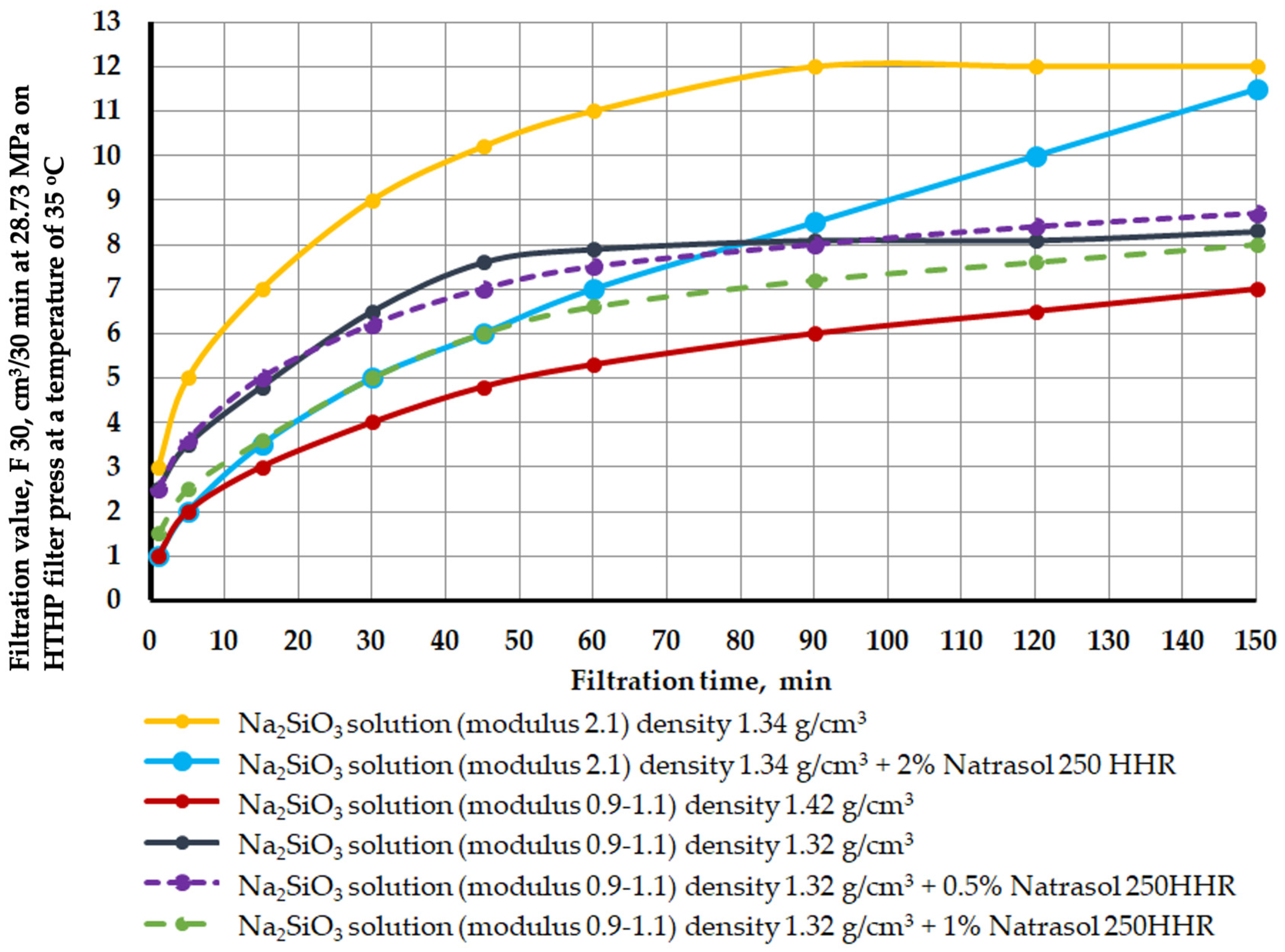
3.5. Study of Filtration Characteristics and Plugging Ability of Blocking Composition under Thermobaric Conditions

Based on field data on the opening of rape-bearing formations at one of the fields in Eastern Siberia, the maximum pressure at the wellhead with a closed blowout preventer (BOP) was 27.36 MPa. In this regard, during the research, the following thermobaric conditions were adopted: pressure, taking into account 5% of the reserve, will be 28.73 MPa, temperature 35 °C.
The study of properties was carried out at a temperature of 35 °C and a pressure drop of 28.73 MPa on an OFITE HPHT dynamic filter press, and a gas booster was used to create the required pressure. The gas booster is similar in principle to a high pressure liquid pump, where a larger piston is connected to a smaller one. The gas supplied from the compressor drives the gas booster mechanism [45].
The dynamics of filtration changes over time for blocking compositions is shown in Figure 9.
It can be seen from the analysis of the curves that the reaction time of most compositions occurs in the range of 80–100 min (inflection on the curve and alignment).
The use of only liquid glass with a silicate module of 2.1 quickly seizes and hardens the salt sample, which makes it not very convenient to use from a technological point of view (yellow line on the graph). For a more uniform liquid glass filtration front through a bulk model, the liquid glass solution was treated with Natrasol 250 HHR hydroxyethyl cellulose. As mentioned earlier, in the discussion of the results under Figure 6, the strongest sample is obtained when processing 2% of the polymer. It is important to note that it is at a polymer concentration of 2% (blue line on the graph) that the filtration is evenly distributed throughout the test. Additional treatment of liquid glass with hydroxyethyl cellulose increases the filtration time to 150 min, which makes it possible for the composition to penetrate a greater distance into the formation. All this confirms the effectiveness of the polymer composition chosen by the authors.
The main task in the development of a blocking composition is the maximum penetration of the composition into the wellbore with a further reaction of precipitation of calcium and magnesium metasilicates [46,47]. For this reason, determination of the penetration depth of the filtrate was carried out on a SkyScan 1173 tomograph. Table 5 shows the penetration depth of the filtrate depending on the composition of the crosslinker.
Based on the results obtained, it can be concluded that all compounds successfully penetrate into the pore space to a depth of 43 mm to 74 mm. At the same time, the greatest penetration depth is observed in the composition based on sodium metasilicate and the polymer additive Natrosol 250 HHR at a concentration of 2% and is 74 mm. The greater penetration depth compared with other compositions can be explained by the optimal structural and rheological characteristics of this composition.
This confirms that the authors have developed and selected the most optimal composition for the isolation of layers under conditions of salt deposits and brine manifestations.

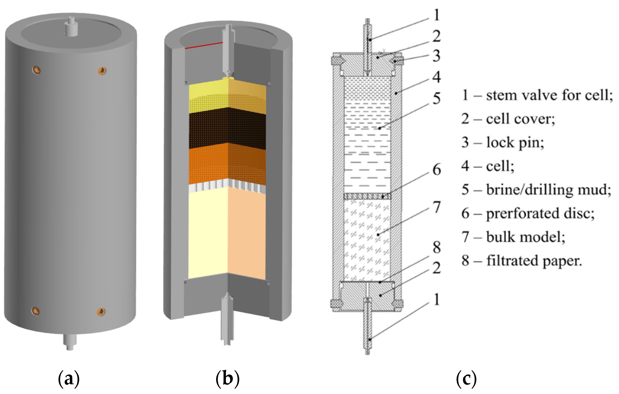
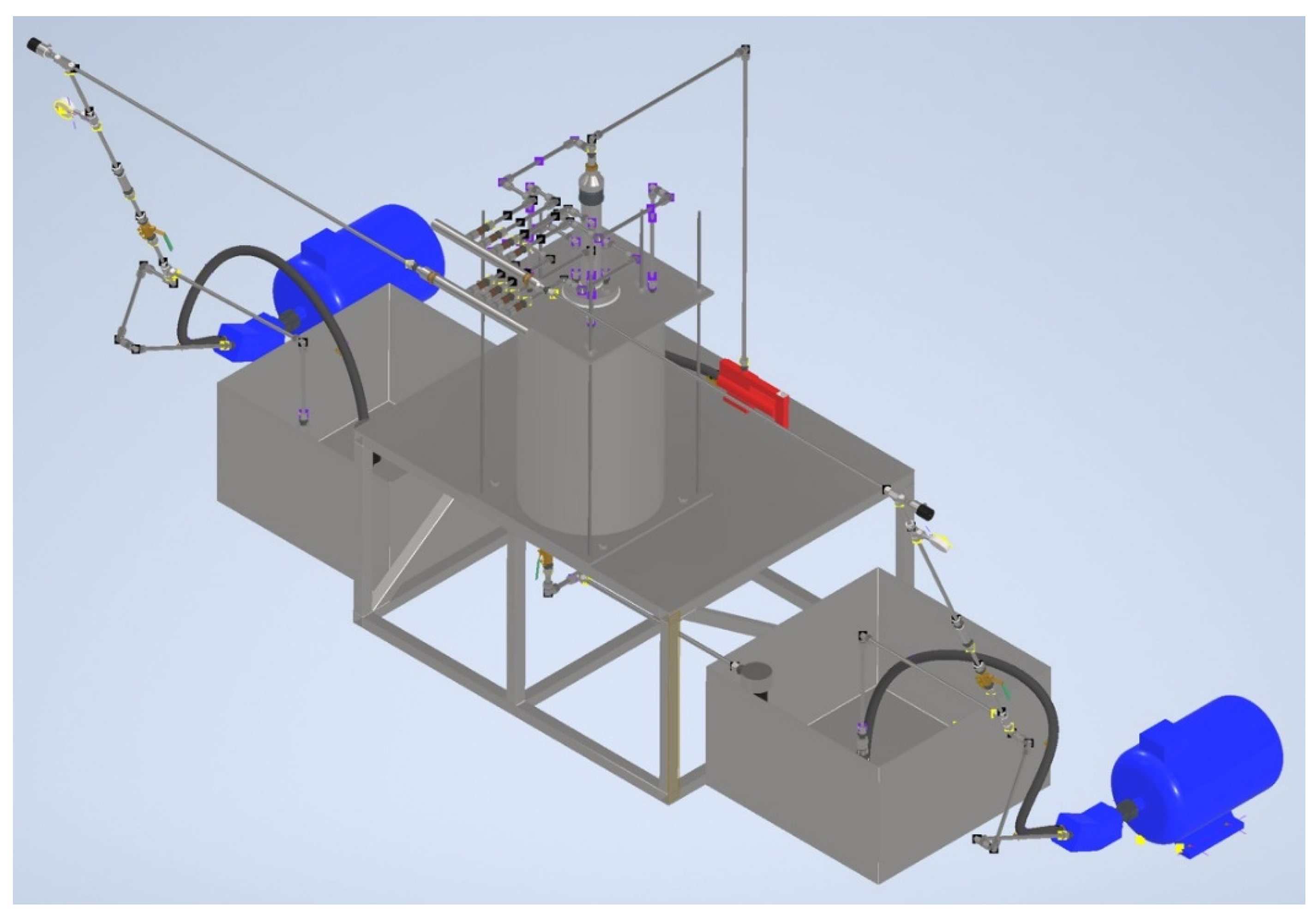
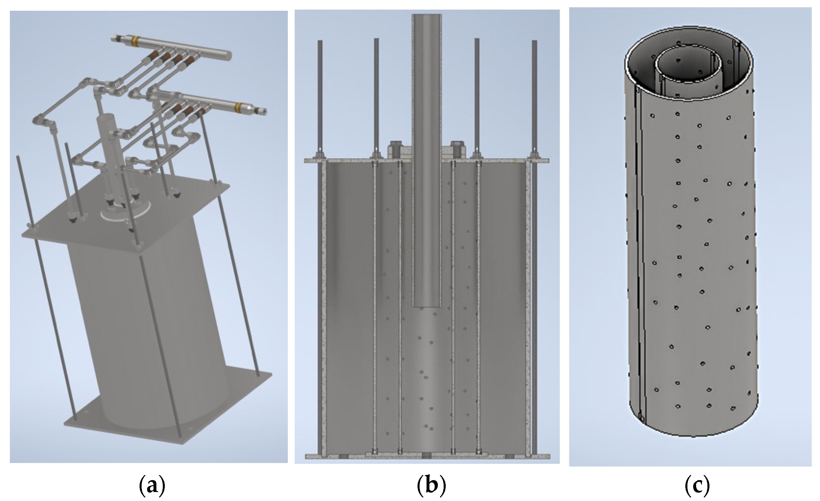
4. Experimental Stand Design

For future research and testing of compositions for blocking formations in conditions as close as possible to the conditions for the use of such compositions in real wells, an experimental stand was designed.
The stand design allows you to simulate different well and reservoir conditions. In particular, it is possible to change both the type of formation fluid supplied from the formation, and the bulk model itself, which imitates rock on the walls of the well. With the help of hydraulic piping of the stand, it is possible to simulate various pressure drops in the well, for example, to make the formation pressure higher than the well pressure for development and, conversely, for pushing process fluid into the formation [48].
At the initial stage of designing the stand, a basic hydraulic diagram of the device was created. The main working element of the stand is the working area in which the simulation of water intrusion will take place. Water intrusion modeling includes:
  • Creation of a reservoir model saturated with fluid;
  • Creation of a well model filled with drilling fluid;
  • Creation of a model of the drill string, through which the hardening composition will be injected.
The designed stand assembly with all elements is shown in Figure 10.
The main working area of the test bench consists of a chamber filled with soil and an external tank. The chamber is designed to be collapsible so that the tests can be repeated many times. At the same time, the connection of the chamber parts is strong enough to withstand the pressure of the drilling fluid column and injection of the blocking composition.
The designed chamber consists of an inner and outer shell made of steel pipes and is shown in Figure 11a. The pipes are bisected longitudinally and perforated (Figure 11b).
The hydraulic connection between the brine and drilling fluid supply lines and the working area is through a distribution manifold, shown in Figure 11c.
The blocking composition is fed into the inner cavity of the chamber through the central pipe, which imitates the drill pipe string. Drilling and process fluids are also supplied to the working area from specially prepared containers using axial piston pumps [49,50].
The use of the stand will allow simulation of the process of formation fluid manifestation during drilling and studying the mechanism of formation blocking using various blocking compositions.
In the future, the developed stand can be used to study other isolation methods.

5. Discussion

The existing technological methods of resisting brine blowout given in the article demonstrate inefficiency in the conditions of blocking formations containing highly mineralized formation fluid. The method of isolation given in the source [22] using polyacrylamide derivatives does not result in a positive effect, due to the fact that the polymer molecules cannot dissolve sufficiently in water with a total mineralization of 0.35–0.4 kg/L and higher. Other methods, which involve changing the layout of drill pipes and running profile covers and casing strings, lead to a significant increase in well construction time due to additional tripping operations and the installation of cement plug bridges in problematic horizons, as in [21], because of poor adhesion of the cement stone with the rock in the conditions of salt deposits.
The research methodology, presented for the first time, makes it possible to fully assess in detail the nature of the problem associated with brine blowout with a detailed analysis of the chemical composition of the formation fluid and by conduct research on core samples taken from the roof of developing horizons. After all, it was the detection of a high concentration of metals and salts in the brine that made it possible to determine the future method of blocking the formation.
The developed polymer blocking composition takes into account the shortcomings described in other studies. The use of water glass makes it possible to crystallize the reservoir fluid because of the reaction with metal cations. An additional increase in the viscosity of the mixture due to the treatment of the composition with HEC allows not only to increase the strength of the resulting gel, but also to increase the thickening time for successful injection of the composition into fractured-pore interlayers with brine.
This paper presents an integrated approach to the study of the problem of brine blowout, including the study of the chemical composition of brine, which should underlie not only design solutions, but also operating procedures for trouble-free drilling.
In summary, it can be noted that in this work an attempt was made not only to assess the blowout problem but to also establish the causes of these complications. The necessity of using a blocking mechanism with a crystallization reaction with metal cations contained in reservoir water, rather than simply pumping various fractions of LCM into fractured pore horizons, is proved.

6. Conclusions

The following conclusions were made:
  • The choice of a method for isolating formations without stopping the drilling process and changing the borehole assembly to minimize non-productive time is justified.
  • Based on the methods of atomic emission spectrometry, spectrophotometry, and titrimetry, the composition of the reservoir fluid was studied in detail. The concentration of chlorides reaches 60%, and divalent salts of calcium chloride (CaCl2) and magnesium (MgCl2) 26% and 35.7%. The identification of these components made it possible to put forward and experimentally confirm the idea of the possibility of crystallization of metal cations upon interaction with Na2SiO3 with the formation of an insoluble precipitate.
  • Based on the study of the compatibility of polymers of different groups, it was found that the most suitable additive for thickening the gel and increasing the hardening time of the composition is HEC. Successful combination with brine is explained by a more flexible macromolecule and the nonionic nature of the functional groups: -CH2OCH2CH2OH and -HC-OCH2CH2OH. The explanation of the interaction process by means of hydrogen bonds, the subsequent intermolecular interweaving of molecules, and the alignment of an ordered structure around the HEC molecule with an increase in viscosity confirmed the effectiveness of the selected additive.
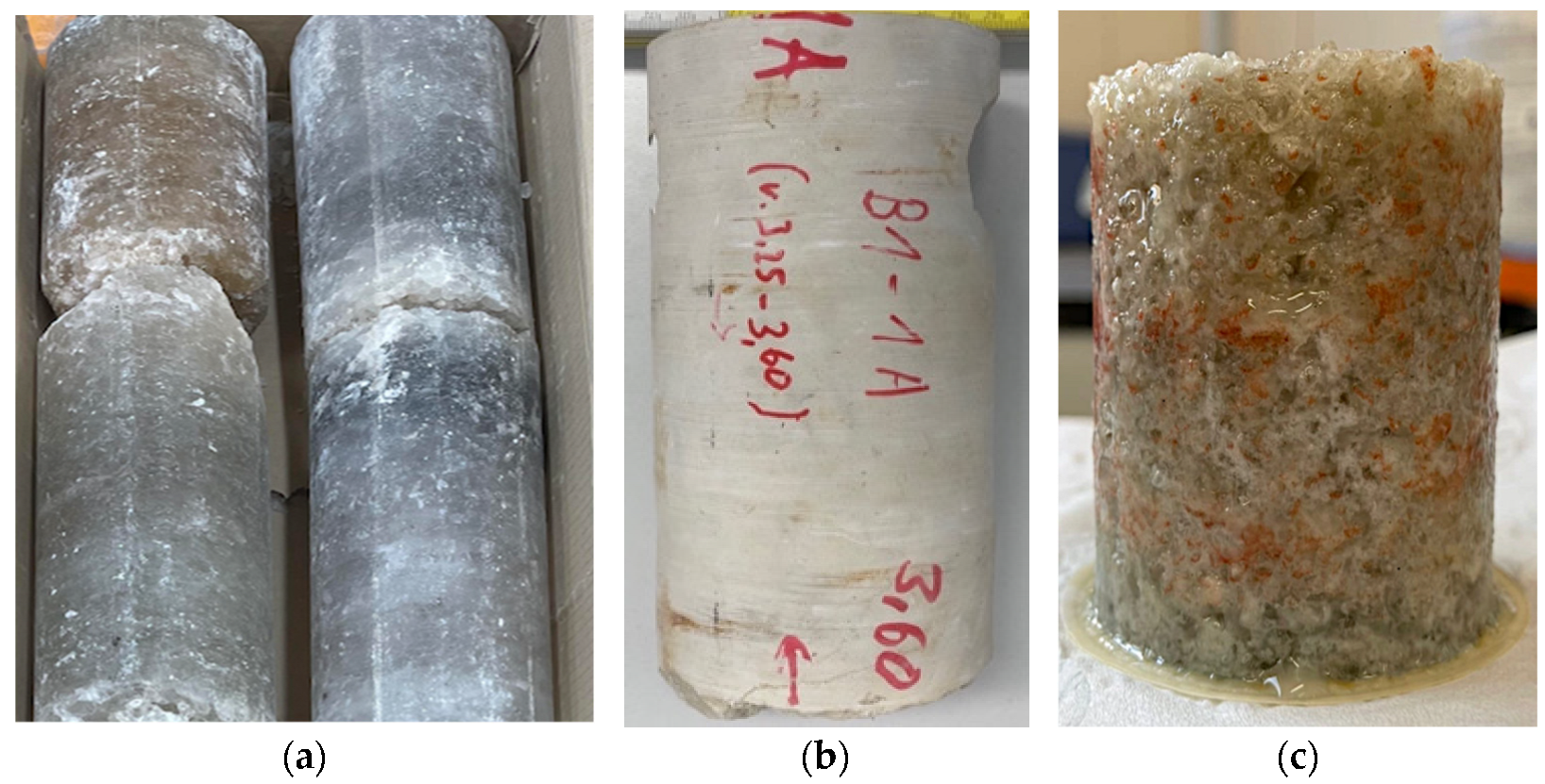
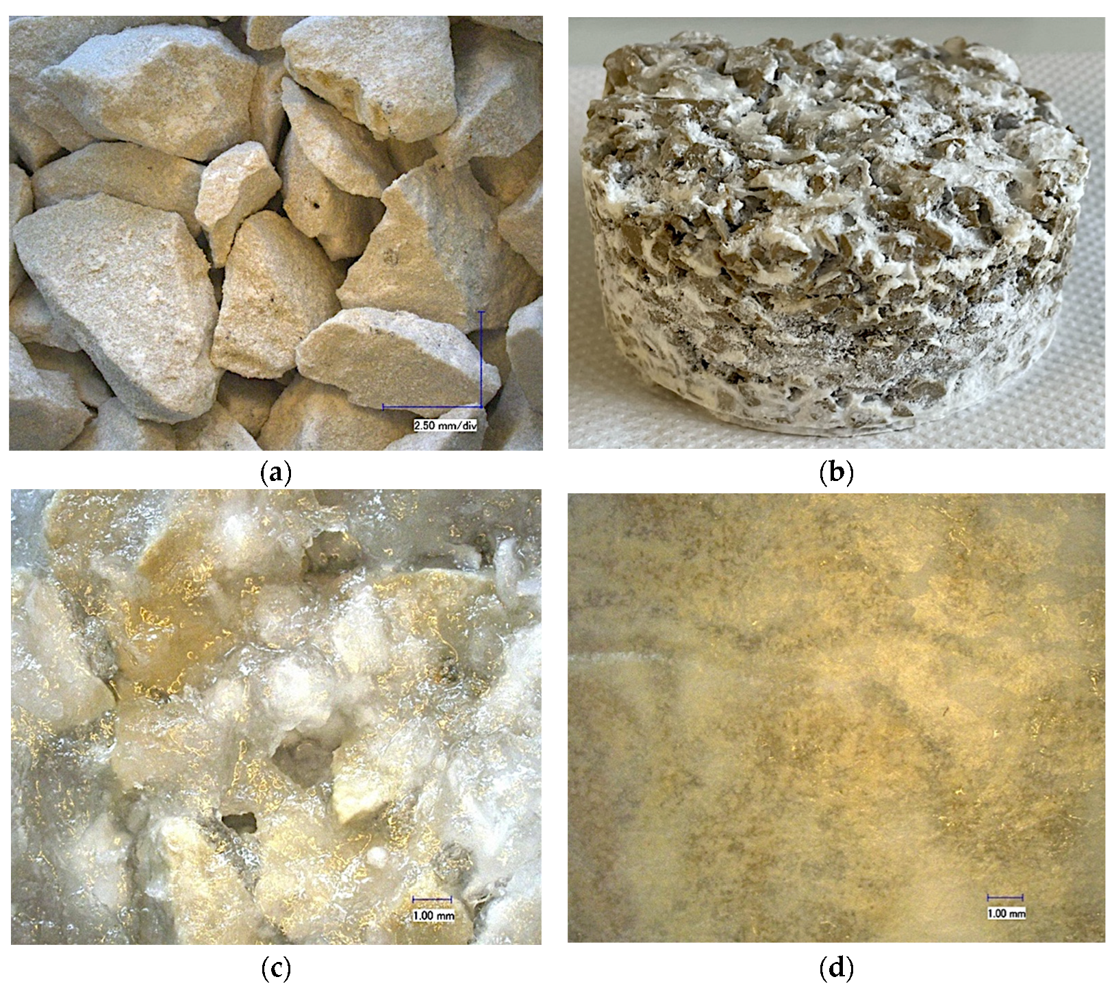
  • Filtration of the polymer composition through a bulk model from the core of developing formations saturated with brine at a pressure of 28.73 MPa and 35 °C made it possible to establish the optimal concentration of the polymer at 2%, dissolved in sodium metasilicate with a silicate modulus of 2.1 and a total density of the composition of 1.34 g/cm3. After filtering the composition, the bulk model had the highest strength with the formation of a hard crust on the upper part of the sample.
  • Based on tomographic studies, it was found that the depth of penetration of the filtrate during the injection of the developed blocking composition into the core of developing layers was 74 mm.
  • For subsequent tests, an experimental stand was developed to simulate the process of isolation of layers under conditions of back pressure from the side of the layer. Laboratory tests on the stand will allow not only testing of various compositions to resist losses and blowout, but also allow exploration of other technical methods for isolating problem horizons.
  • The use of the developed method of blocking formations will allow oil and gas companies to reduce non-productive time associated with the elimination of brine manifestations and accelerate the transition to further development of productive hydrocarbon deposits.
  • The developed research methodology will allow scientists and oil engineers to select and develop new types of blocking compositions based on the study of physical and chemical interaction with formation fluid components.
The results of the research are planned to be tested in the near future at a real field in wells complicated by brine blowout and fluid losses.

Author Contributions

Conceptualization, M.D. and D.S.; methodology, E.K.; software, D.S. and E.K.; validation, E.K.; formal analysis, D.S.; investigation, D.S., E.K. and F.R.; resources, D.S.; data curation, R.A.; writing—original draft preparation, D.S. and E.K.; writing—review and editing, D.S. and E.K.; visualization, D.S.; supervision, M.D., F.R. and R.A.; and project administration, E.K. All authors have read and agreed to the published version of the manuscript.

Funding

This research received no external funding.

Data Availability Statement

The data presented in this study are available on request from the corresponding author. The data are not publicly available due to its storage in private networks.

Conflicts of Interest

The authors declare no conflict of interest.

Nomenclature

AHFPAbnormally high formation pressure
BOPBlowout preventer
DSSDynamic shear stress
FHLSFerrochrome lignosulfonate
HECHydroxyethylcellulose
HPHTHigh pressure and high temperature
LCMLoss circulation materials
PACPolyanionic cellulose

References

  1. Vakhromeev, A.G.; Sverkunov, S.A.; Ilin, A.I. Mining and Geological Conditions of Drilling Brine Productive Zones with Abnormally High Reservoir Pres-sure in Natural Cambrian Reservoirs of the Kovykta Gas Condensate Field. Proc. Sib. Dep. Sect. Earth Sci. Russ. Acad. Nat. Sci. 2016, 2, 74–78. [Google Scholar] [CrossRef]
  2. Dvoynikov, M.; Kuchin, V.; Mintzaev, M. Development of viscoelastic systems and technologies for isolating water-bearing horizons with abnormal formation pressures during oil and gas wells drilling. J. Min Inst. 2021, 247, 57–65. [Google Scholar] [CrossRef]
  3. Ageev, S.A.; Rakhimov, N.V.; Kiryakov, G.A. Strategic Aspects, Technical and Technological Solutions for Improving Well Workover Efficiency. Bull. Assoc. Drill. Contractors 2016, 4, 13–20. [Google Scholar]
  4. Goronovich, S.N. Genesis of brine collectors and conditions of their plugging during well construction in the Orenburg region. Environ. Prot. Oil Gas Ind. 2007, 6, 39–43. [Google Scholar]
  5. Vakhromeev, A.G.; Gorlov, I.V. Fountain manifestations of extremely saturated lithium-bearing brines in wells in the south of the Siberian Platform: Drilling, testing, forecasting of fluid systems with AHFP. In Proceedings of the All-Russian Conference on Groundwater of the East of Russia XII, Novosibirsk, Russia, 18–22 June 2018; pp. 27–33. [Google Scholar]
  6. Ushivtseva, L.F. Geological risks and environmental safety of well drilling in regions with the development of salt dome tectonics. Geoecological problems of our time and ways to solve them. In Proceedings of the II All-Russian Scientific and Practical Conference, Oryol, Russia, 6 October 2020; pp. 103–113. [Google Scholar]
  7. Feng, Y.; Gray, K. Review of fundamental studies on lost circulation and wellbore strengthening. J. Pet. Sci. Eng. 2017, 152, 511–522. [Google Scholar] [CrossRef]
  8. Al-salali, Y.Z.; Al-Bader, H.; Vidyasagar, D.; Manimaran, A.; Packirisamy, S.; Al-Ibrahim, A. Paradigm Shift in Reducing Formation Damage: Application of Potassium Formate Water Based Mud in Deep HPHT Exploratory Well. In Proceedings of the SPE Kuwait International Petroleum Conference and Exhibition, Kuwait City, Kuwait, 10–12 December 2012. [Google Scholar] [CrossRef]
  9. Amir, Z.; Saaid, M. The retardation of polyacrylamide by ammonium chloride in high-salinity and high-temperature conditions: Molecular analysis. Polym. Bull. 2020, 77, 5469–5487. [Google Scholar] [CrossRef]
  10. Skokov, V.V. Genesis and chemical composition of brines of the Astrakhan gas condensate field, factors of occurrence and methods of combating brine manifestation. Izv. Vuzov. Min. Mag. 2017, 2, 44–49. [Google Scholar]
  11. Batyrov, M.I.; Savenok, O.V. Development of measures for the prevention and timely elimination of geological complications in the form of brine during drilling of well No. 9 of the Vikanskaya area. Nauka. Technique. Technol. 2020, 1, 44–73. [Google Scholar]
  12. Ma, J.; Yu, P.; Xia, B. Effect of salt and temperature on molecular aggregation behavior of acrylamide polymer. e-Polymers 2019, 19, 594–606. [Google Scholar] [CrossRef]
  13. Ghalambor, A.; Salehi, S.; Shahri, M.P.; Karimi, M. Integrated workflow for lost circulation prediction. In Proceedings of the SPE International Symposium and Exhibition on Formation Damage Control, Lafayette, LA, USA, 26–28 February 2014. [Google Scholar]
  14. Mirabbasi, S.; Ameri, M.; Alsaba, M.; Karami, M.; Zargarbashi, A. The evolution of lost circulation prevention and mitigation based on wellbore strengthening theory: A review on experimental issues. J. Pet. Sci. Eng. 2022, 211. [Google Scholar] [CrossRef]
  15. Ushivtseva, L.F. Hydrogeological characteristics of the zones of brine manifestations of the Astrakhan arch. Geol. Geogr. Glob. Energy 2019, 4, 106–115. [Google Scholar]
  16. Khurshudov, V.A.; Khurshudov, D.V. Characteristic features of the struggle with deposits in the salt deposits of the Upper Jurassic when drilling super-deep wells in the areas of the Eastern Ciscaucasia (Combating the manifestations of brine). Constr. Oil Gas Wells Land Sea 2010, 1, 11–14. [Google Scholar]
  17. Zhu, D.; Bai, B.; Hou, J. Polymer Gel Systems for Water Management in High-Temperature Petroleum Reservoirs: A Chemical Review. Energy Fuels 2017, 31, 13063–13087. [Google Scholar] [CrossRef]
  18. Seright, R. Gel propagation through fractures. SPE Prod. Facil. 2001, 16, 225–231. [Google Scholar] [CrossRef]
  19. Khamityanov, N.K. Technology of isolation of the complication zone by a column of expandable pipes. Onshore Offshore Oil Gas Well Constr. 2011, 1, 19–21. [Google Scholar]
  20. Averkina, E.V.; Shakirova, E.V. Features of the preparation of drilling fluids based on formation water of the Znamenskoye field. Probl. Collect. Prep. Transp. Oil Oil Prod. 2019, 4, 38–46. [Google Scholar]
  21. Khailovsky, V.N. Analysis of geological complications in overproductive deposits at the Astrakhan GCF. Int. Sci. Res. J. 2015, 1, 79–83. [Google Scholar]
  22. Wang, J.; Yan, L.; Liu, F.; Yang, H.; Yin, D. Treatment Technology of Brine Contamination and Barite Settlement for the High Temperature and High Density OBM for Ultra-Deep Well Drilling in Western China. In Proceedings of the International Petroleum Technology Conference, Beijing, China, 26–28 March 2019. [Google Scholar] [CrossRef]
  23. Kovyktinskoe Field. Available online: https://www.gazprom.com/projects/kovyktinskoye/ (accessed on 26 September 2022).
  24. Averkina, E.V. Analysis of brine-producing wells in gas condensate fields of the Irkutsk region. Proc. Sib. Branch Sect. Earth Sci. Russ. Acad. Nat. Sciences. Geol. Prospect. Explor. Ore Depos. 2009, 2, 152–157. [Google Scholar]
  25. Buglov, E.N.; Vaseneva, E.G. Well drilling under conditions of hydrogen sulfide aggression. Bull. ISTU 2013, 12, 121–123. [Google Scholar]
  26. Environmental Regulation 14.1:2:4.261-10; Quantitative Chemical Analysis of Waters. Methodology for Measuring the Mass Concentration of Dry and Calcined Residues in Samples of Drinking, Natural and Waste Water by the Gravimetric Method. RussianGost: Moscow, Russia, 2015.
  27. GOST 18164-72; Drinking Water. Method for Determining the Content of Dry Residue. Introduction 01/01/1974; RussianGost: Moscow, Russia, 1974.
  28. API RP 13I: Laboratory Testing of Drilling Fluids, 9th ed.; American Petroleum Institute: Washington, DC, USA, December 2020.
  29. P1-01.05 M-0044; Guidelines of Rosneft Oil Company PJSC Uniform Technical Requirements for the Main Classes of Chemical Reagents. Rosneft Oil Company: Moscow, Russia, 2016.
  30. Petrov, N.A. Study of salt-resistant polymeric reagents. Electron. J. Oil Gas Bus. 2016, 2, 38–54. [Google Scholar] [CrossRef] [Green Version]
  31. Babajide, A.; Adebowale, O.; Adesina, F.; Churchill, A.; Ifechukwu, M. Effects of Temperature and Pressure on Shale Cuttings Dispersion in Water Based Mud WBM Using NACL, CACL2, KCL Salts as Primary Inhibiting Agents and Polymer XCD Xanthan Gum as Secondary Inhibiting Agent. In Proceedings of the SPE Nigeria Annual International Conference and Exhibition, Lagos, Nigeria, 2–4 August 2016. [Google Scholar] [CrossRef] [Green Version]
  32. Howard, S.; Kaminski, L.; Downs, J. Xanthan Stability in Formate Brines-Formulating Non-Damaging Fluids for High Temperature Applications. In Proceedings of the SPE European Formation Damage Conference and Exhibition, Budapest, Hungary, 3–5 June 2015. [Google Scholar] [CrossRef]
  33. Magzoub, M.; Salehi, S.; Hussein, I.; Nasser, M. Development of a Polyacrylamide-Based Mud Formulation for Loss Circulation Treatments. ASME J. Energy Resour. Technol. 2021, 143, 073001. [Google Scholar] [CrossRef]
  34. Ulyasheva, N.; Leusheva, E.; Galishin, R. Development of the drilling mud composition for directional wellbore drilling considering rheological parameters of the fluid. J. Min. Inst. 2020, 244, 454–461. [Google Scholar] [CrossRef]
  35. Karsani, K.; Al-Muntasheri, G.; Sultan Hussein, I. Impact of salts on polyacrylamide hydrolysis and gelation: New insights. J. Appl. Polym. Sci. 2014, 131. [Google Scholar] [CrossRef]
  36. Islamov, S.R.; Bondarenko, A.V.; Mardashov, D.V. A selection of emulsifiers for preparation of invert emulsion drilling fluids. In Topical Issues of Rational Use of Natural Resources; Taylor & Francis: London, UK, 2020; pp. 487–494. [Google Scholar] [CrossRef]
  37. Zulhelmi, A.; Said, I. In situ organically cross-linked polymer gel for high-temperature reservoir conformance control: A review. Polym. Adv. Technol. 2018, 30, 13–39. [Google Scholar] [CrossRef] [Green Version]
  38. Islamov, S.R.; Bondarenko, A.V.; Mardashov, D.V. Substantiation of a well killing technology for fractured carbonate reservoirs. In Youth Technical Sessions Proceedings: VI Youth Forum of the World Petroleum Council–Future Leaders Forum; Taylor & Francis: London, UK, 2019; pp. 256–264. [Google Scholar] [CrossRef]
  39. Koshelev, V.N. Cleanout of Oil and Gas Wells; Nedra Publishers: Moscow, Russia, 2019; p. 687. [Google Scholar]
  40. Morenov, V.; Leusheva, E.; Liu, T. Development of a Weighted Barite-Free Formate Drilling Mud for Well Construction under Complicated Conditions. Polymers 2021, 13, 4457. [Google Scholar] [CrossRef]
  41. Mao, H.; Yang, Y.; Zhang, H.; Zheng, J.; Zhong, Y. Conceptual Design and Methodology for Rheological Control of Water-Based Drilling Fluids in Ultra-High Temperature and Ultra-High Pressure Drilling Applications. J. Pet. Sci. Eng. 2020, 188, 106884. [Google Scholar] [CrossRef]
  42. Zhou, H.; Deville, J.P.; Davis, C.L. Novel High Density Brine-Based Drill-In Fluids Significantly Increased Temperature Limit for HP/HT Applications; SPE: London, UK, 17 March 2015. [Google Scholar] [CrossRef]
  43. Liu, T.; Leusheva, E.L.; Morenov, V.A.; Li, L.; Jiang, G.; Fang, C.; Zhang, L.; Zheng, S.; Yu, Y. Influence of polymer reagents in the drilling fluids on the efficiency of deviated and horizontal wells drilling. Energies 2020, 18, 4704. [Google Scholar] [CrossRef]
  44. Nikolaev, N.I.; Leusheva, E.L. low-density cement compositions for well cementing under abnormally low reservoir pressure conditions. J. Min. Inst. 2019, 236, 194. [Google Scholar] [CrossRef] [Green Version]
  45. Mardashov, D.V.; Bondarenko, A.V.; Raupov, I.R. Technique for calculating technological parameters of non-Newtonian liquids injection into oil well during workover. J. Min. Inst. 2022, 253, 41–48. [Google Scholar] [CrossRef]
  46. Mohamed, A.; Salehi, S.; Ahmed, R. Significance and Complications of Drilling Fluid Rheology in Geothermal Drilling: A Review. Geothermics 2021, 93, 102066. [Google Scholar] [CrossRef]
  47. Abbas, A.; Bashikh, A.; Hayder, A.; Haider, M. Intelligent decisions to stop or mitigate lost circulation based on machine learning. Energy 2019, 183, 1104–1113. [Google Scholar] [CrossRef]
  48. Yang, G.; Liu, T.; Blinov, P.A.; Wang, Y.; Feng, Y. Temperature regulation effect of low melting point phase change microcapsules for cement slurry in nature gas hydrate-bearing sediments. Energy 2022, 253, 124115. [Google Scholar] [CrossRef]
  49. Ali, A.; Si, Q.; Yuan, J. Investigation of energy performance, internal flow and noise characteristics of miniature drainage pump under water–air multiphase flow: Design and part load conditions. Int. J. Environ. Sci. Technol. 2022, 19, 7661–7678. [Google Scholar] [CrossRef]
  50. Koteleva, N.; Buslaev, G.; Valnev, V.; Kunshin, A. Augmented Reality System and Maintenance of Oil Pumps. Int. J. Eng. 2020, 33, 1620–1628. [Google Scholar] [CrossRef]
Figure 1. Scheme of the chamber of the modified cell (500 mL) of the OFFITE HTHP filter press for determining the curing ability of blocking compounds. (a) 3D layout of the cell; (b) 3D layout of the cell in section; and (c) cell drawing with positions.
Energies 15 07415 g001
Figure 2. Analysis of the dry residue of formation fluid using the calibration graph method. (a) Sample No. 1, bottom hole 2153 m (after a day of overflow); (b) Sample No. 2, bottom hole 2236 m; (c) Sample No. 3, bottom hole 2236 m; and (d) Sample No. 4, bottom hole 2153 m (bottom hole pack).
Energies 15 07415 g002
Figure 3. Idealized chemical structure of HEC with degree substitution 2.0 and molar substitution 2.5.
Energies 15 07415 g003
Figure 4. Rheological profiles of mixtures of heavy mud with brine depending on their ratio before heating under normal conditions.
Energies 15 07415 g004
Figure 5. Rheological profiles of mixtures of heavy mud with brine depending on their ratio after heating at 60 °C for 8 h.
Energies 15 07415 g005
Figure 6. Filtration change over time in brine crosslinkers as a function of silicate modulus, density, and hydroxyethyl cellulose content Natrosol 250 HHR.
Energies 15 07415 g006
Figure 7. Core samples and bulk model after a filtration experiment. (a) Salt core from a brine-producing horizon; (b) carbonate core; and (c) general view of the bulk model after pumping the blocking compound.
Energies 15 07415 g007
Figure 8. Bulk model with a fraction of ground carbonate rock more than 2.5 mm after pumping the hardening composition. (a) Snapshot of the bulk model at ×100 magnification on a Keyence VHX-600 microscope; (b) general view of the bulk model after the experiment; (c) snapshot of the bulk model after the experiment at ×100 magnification (top view); and (d) photograph of the bulk model after the experiment at ×100 magnification on a microscope (bottom view).
Energies 15 07415 g008
Figure 9. Filtration change over time in brine crosslinkers as a function of silicate modulus, density, and hydroxyethyl cellulose content Natrosol 250 HHR at 35 °C and 28.73 MPa.
Energies 15 07415 g009
Figure 10. Experimental stand in the assembly.
Energies 15 07415 g010
Figure 11. Working area of the stand. (a) Connecting the distribution manifold to the work area; (b) axial section of the working area; and (c) perforated chamber.
Energies 15 07415 g011
Table 1. Results of the analysis of the dry residue of formation fluid by the method of standard additions.
No.Mass Concentration of a Chemical ElementResearch Results, mg/dm3Research Method
Sample No. 1Sample No. 2Sample No. 3Sample No. 4
1Lithium740 ± 96645 ± 84655 ± 85760 ± 99Atomic emission spectrometry
2Bor81 ± 11126 ± 16121 ± 1647 ± 6
3Barium114 ± 15104 ± 14122 ± 16110 ± 14
4Calcium166,000 ± 28,22099,400 ± 16,898103,000 ± 17,510163,000 ± 27,710
5Magnesium34,800 ± 452476,300 ± 991977,600 ± 10,08833,000 ± 4290
6Potassium3360 ± 437967 ± 1261150 ± 1502830 ± 368
7Sodium1510 ± 196961 ± 1251140 ± 1481490 ± 194
8Iron1150 ± 127503 ± 55546 ± 601220 ± 134
9Manganese227 ± 3087 ± 1199 ± 13234 ± 30
10Strontium2730 ± 3403011 ± 4224520 ± 6331640 ± 230
11Phosphate-ion20 ± 445 ± 945 ± 950 ± 10Spectrophotometry
12Sulfate-ion2882 ± 2592209 ± 1992305 ± 2072882 ± 259Titrimetry
13Chloride-ion388,275± 58,241386,300 ± 57,945396,500± 59,475387,750± 58,163
14Bicarbonate-ion1373 ± 1651525 ± 1831068 ± 1281373 ± 165
Table 2. Changes in the structural and rheological characteristics of brine during the processing of 2% polymers.
Rheological CharacteristicsUnitsMaterial Name
BrineAqua PAC L 2%Aqua PAC R 2%Natrosol
2%
Biosin
2%
Starch Poly KR 2%
Torsion angles: ϴ600degree232528332925
ϴ300degree121316201713
ϴ200degree89111499
ϴ100degree455955
ϴ66degree112611
ϴ3degree111311
Plastic viscosity, ηpmPa·s111212131212
DSSdPa552035255
Gels 10 sdPa111111
Gels 10 mindPa111221
Densitykg/m3139013901390139013901390
Table 3. Study of the effect of polymer concentration on the structural and rheological characteristics of brine under normal conditions.
Rheological CharacteristicsUnitsMaterial Name and Concentration
Natrosol 250 HHR, %Biosin, %
12357101235710
Torsion angles: ϴ600degree25252960230>300242525272932
ϴ300degree13131532130121313141517
ϴ200degree891022898899911
ϴ100degree5551148445556
ϴ6degree11112111122
ϴ3degree11112111122
Plastic viscosity, ηpmPa·s1212142830121212131415
DSSdPa551520146055555
Gels 10 sdPa11222111222
Gels 10 mindPa22224111222
Table 4. Study of the effect of polymer concentration on the structural and rheological characteristics of brine at a temperature of 35 °C and a pressure of 8.1 MPa.
Rheological CharacteristicsUnitsMaterial Name and Concentration
Natrosol 250 HHR, %Biosin, %
12357101235710
Torsion angles: ϴ600degree26252955226>300222523253031
ϴ300degree15141633133111013141615
ϴ200degree7811218710678711
ϴ100degree6771251676454
ϴ6degree12112111122
ϴ3degree12112111122
Plastic viscosity, ηплmPa·s1313122932141210121315
DSSdPa451318148145445
Gels 10 sdPa22222211222
Gels 10 mindPa22223111222
Table 5. The dependence of the filtrate penetration zone depending on the composition.
No.CompoundPenetration Zone, Rf, mm
1Na2SiO3 solution (modulus 2.1) density 1340 kg/m3 250 HHR56
2Na2SiO3 solution (modulus 2.1) density 1340 kg/m3 + 2% Natrosol 250 HHR74
3Na2SiO3 solution (modulus 0.9–1.1) density 1420 kg/m343
4Na2SiO3 solution (modulus 0.9–1.1) density 1320 kg/m352
5Na2SiO3 solution (modulus 0.9–1.1) density 1320 kg/m3 + 0.5% Natrosol 250 HHR63
6Na2SiO3 solution (modulus 0.9–1.1) density 1320 kg/m3 + 1.0% Natrosol 250 HHR65
Publisher’s Note: MDPI stays neutral with regard to jurisdictional claims in published maps and institutional affiliations.

