Article

Impedance Compensation Method Considering Unbalanced Ground Fault with SFCL in a Power Distribution System

Department of Electrical Engineering, Soongsil University, 369, Sangdo-ro, Dongjak-gu, Seoul 156-743, Korea
*
Author to whom correspondence should be addressed.
Energies 2022, 15(19), 7405; https://doi.org/10.3390/en15197405
Submission received: 18 August 2022 / Revised: 5 September 2022 / Accepted: 7 September 2022 / Published: 9 October 2022
(This article belongs to the Section A1: Smart Grids and Microgrids)

Abstract

:
As the energy demand increases due to the developing electric power industry, the fault current becomes higher during the fault time. A new approach is needed to reduce a fault current in a power distribution system, since the fault currents influence other protective devices’ operation. To decrease the fault current, the superconducting fault current limiter (SFCL) has been suggested. The SFCL has no power loss with no effect on a power distribution system because the SFCL impedance only occurs during the fault time. However, the SFCL can reduce the fault current; it causes the trip time delay of the over current relay (OCR). Compensation methods for the balanced fault have been invented in previous studies, while research on unbalanced ground fault compensation are few. In this paper, the compensation method configured with impedance components of a power distribution system is introduced to eliminate the influence of the SFCL on the OCR. In addition, the components of the SFCL impedance are removed from the characteristic equation of the OCR. To verify the effect of the impedance compensation method, fault simulations are carried out in 3 types of ground faults using PSCAD/EMTDC.

1. Introduction

The energy demand of a power system increases due to the development of the electric power industry and the complexity of a power system. As a result, the fault current increases and power devices exceed their capacities and their operation is affected. It is necessary to increase the capacity of devices in a power distribution system to reduce the fault current, but it is economically burdensome.
Another way to limit the increasing fault current is by installing a superconducting fault current limiter (SFCL). The SFCL is economical in that it has no loss and quickly limits the fault current in a power distribution system by the quench occurrence of the high temperature superconducting (HTSC) element. In normal operation, the resistance of the HTSC element is zero; the SFCL has no effect on a power distribution system. If the fault occurs, the resistance of the HTSC element obtains a value and performs the fast fault current limiting operation. Different types of the SFCLs exist, such as typically resistive-type, transformer-type, flux-lock-type, hybrid type and trigger-type SFCL. The trigger-type SFCL has the advantage of minimizing the power consumption of the HTSC element by using a switching operation [1,2,3,4,5,6,7,8].
Though the SFCL effectively controls the fault current, the SFCL obstructs the activation of the OCR. The OCR has inverse characteristics for the fault current, so the trip time of the OCR is delayed as the fault current decreases due to the SFCL. The trip delay problem of the OCR (due to the fault current limiting operation of the SFCL) has been found, in many previous studies, to be resolved by resetting the characteristic equation of the OCR using the current or voltage components. However, these previous reports only deal with balanced ground fault situations and may cause malfunction in unbalanced ground faults, since the fault current is different in each ground fault. All ground types of faults must be considered because unbalanced ground fault such as single-line and double-line ground faults (SLG, DLG) occur more than balanced ground faults such as triple-line ground faults (TLG) [9,10,11,12,13,14,15,16,17,18,19,20,21].
In this paper, the impedance compensation method for the OCR using power distribution system components are suggested to lessen the effect of the SFCL. Research on balanced ground faults were suggested in previous studies, so the impedance compensation method for unbalanced ground fault is investigated. To prove the impedance compensation method for the OCR operation, it is derived through the simulation comparison by Power Systems Computer Aided Design (PSCAD) and Electro Magnetic Transient DC analysis program (EMTDC).

2. Configuration of Power Distribution System with SFCL

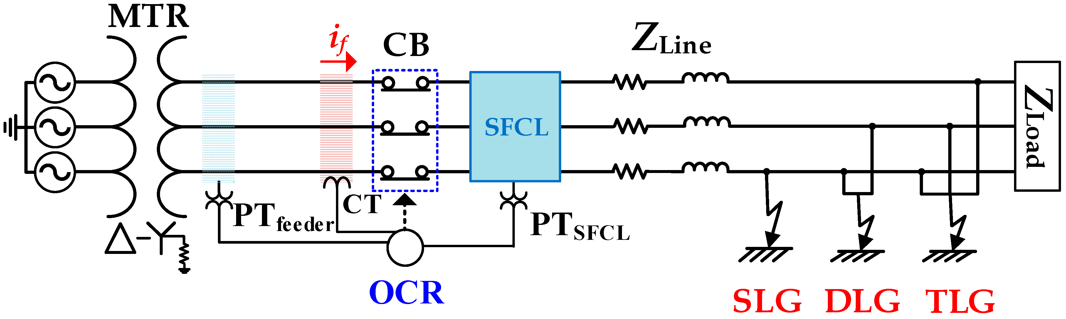
2.1. Structure of Power Distribution System

A power distribution system, simulated in Figure 1, consists of a single feeder line, source, main transformer (MTR), loads, the over current relay (OCR), the circuit breaker (CB) and trigger-type SFCL. The OCR measures three phase feeder currents through the current transformer (CT), and three phase feeder voltages and the SFCL voltages in three phases are estimated by the potential transformer (PT). After that, three phase currents and voltages are changed into the sequence components (positive, negative, zero). The OCR controls the CB using sequence components of feeder currents against the fault situation. These sequence components of feeder currents and voltages are used to derive the sequence impedance components, which are applied to the impedance compensation method of the OCR described in Section 3.2. In addition, a load of 5 [MW] (ZLoad) is installed at the end point of the feeder. The feeder lines (ZLine) have resistance and reactance in each phase, and conductance is set very low to omit the mutual impedance, since it affects the formation of the impedance compensation method. The three types of ground fault, which are the single-line ground fault (SLG), double-line ground fault (DLG) and the triple-line ground fault (TLG), emerge at the 10 [km] point from the feeder. One of the three ground faults occurs and has different results, as shown in Section 4. Specifications of power distribution system are shown in Table 1 [22].

2.2. Trigger Type SFCL Modeling

Figure 2 shows three phase trigger type SFCL, which controls the fault current by activating the breaker with the control circuit. The control circuit measures the voltage of the high temperature superconducting (HTSC) element (VSC) and the current (ICLR) of the current limiting reactor (CLR). Then, the control circuit sends a close/open signal to the breaker. In normal operation, the current only flows into the HTSC element since it is zero resistance. When the fault occurs, the fault current exceeds the critical current (IC) and the resistance of the HTSC element obtains a value. If the voltages of the HTSC element (VSC) exceed the setting voltage (VSet), the control circuit makes a signal to open the breaker and the fault current flows into the CLR due to the opening of the breaker. If the CLR current decreases more than the setting current (ISet) after the fault disappears, the control circuit sends a signal to close the breaker and the current again flows into the HTSC element by the closing operation of the breaker. Therefore, trigger-type SFCL is an economic model due to the trigger operation with the HTSC element and the control circuit. To improve the trip time delay of OCR, a suggested impedance compensation method will be used with the SFCL. Detailed parameters of trigger type SFCL are described in Table 2.

3. Operational Characteristic of over Current Relay

3.1. Equivalent Impedance of Power Distribution System

The equivalent impedance of a power distribution system is represented in the matrix to discuss the effect of the SFCL on a power distribution system. The impedance matrix equations are presented in 3 cases of the ground fault:
  • Case 1: Single-line ground fault (SLG)
  • Case 2: Double-line ground fault (DLG)
  • Case 3: Triple-line ground fault (TLG)
The impedance matrix equations are expressed in the sequence components ( Z f e e d e r 0 P N ) and three phases’ components ( Z f e e d e r a b c ) . In normal operation, three phase and sequence impedance matrix equations are shown in (1).
Z f e e d e r a b c = Z f e e d e r 0 P N = [ Z l i n e + Z l o a d 0 0 0 Z l i n e + Z l o a d 0 0 0 Z l i n e + Z l o a d ]
  Z l i n e is the line impedance and Z l o a d is the load impedance described in Figure 1. A main diagonal of Z f e e d e r a b c is three phase feeder impedance and Z f e e d e r 0 P N main diagonal called the self-impedance is the sequence components of the feeder impedances. An off diagonal of Z f e e d e r a b c and Z f e e d e r 0 P N are the mutual impedances and they are all zero-value, as described in Section 2.1. These two impedance matrix equations are the same before the fault period. After the fault occurs, Z f e e d e r a b c and Z f e e d e r 0 P N are expressed in 3 cases on the ground fault type.
Case 1, the single-line ground fault (SLG) occurs in the a-phase, Z l o a d disappears in a faulted phase and the SFCL impedances ( Z S F C L ) are added in each phase at Z f e e d e r a b c shown in (2). Z f e e d e r a b c is converted to Z f e e d e r 0 P N by using the convert Equations (3) and (4).
Z f e e d e r a b c = [ Z l i n e + Z S F C L 0 0 0 Z l i n e + Z l o a d + Z S F C L 0 0 0 Z l i n e + Z l o a d + Z S F C L ]  
A = [ 1 1 1 1 a 2 a 1 a a 2 ] ,   a = 1 120 ˚
Z 0 P N = A 1 Z a b c A
Z f e e d e r 0 P N is shown in (5) derived from (2) to (4). In (5), only a main diagonal of Z f e e d e r 0 P N has the Z S F C L , whereas an off diagonal has only the load impedances. A main diagonal is the self impedance and off diagonal is the mutual impedance. As seen in (5), the SFCL only affects the main diagonal called the self-impedance in a power distribution system.
Z f e e d e r 0 P N = 1 3 [ 3 ( Z l i n e + Z S F C L ) + 2 Z l o a d Z l o a d Z l o a d Z l o a d 3 ( Z l i n e + Z S F C L ) + 2 Z l o a d Z l o a d Z l o a d Z l o a d 3 ( Z l i n e + Z S F C L ) + 2 Z l o a d ]
Case 2, the double-line ground fault (DLG) appears in the ab-phase, Z l o a d disappears from the faulted phase and Z S F C L is added in each phase shown in (6). Z f e e d e r 0 P N shown in (7) is derived from (6) and the convert Equations (3) and (4).
Z f e e d e r a b c = [ Z L i n e + Z S F C L 0 0 0 Z L i n e + Z S F C L 0 0 0 Z L i n e + Z L o a d + Z S F C L ]
Z f e e d e r 0 P N = 1 3 [ 3 ( Z l i n e + Z S F C L ) + Z l o a d a Z l o a d a 2 Z l o a d a 2 Z l o a d 3 ( Z l i n e + Z S F C L ) + Z l o a d a Z l o a d a Z l o a d a 2 Z l o a d 3 ( Z l i n e + Z S F C L ) + Z l o a d ]
Case 3, when the triple-line ground fault (TLG) occurs, Z l o a d is disappeared and Z S F C L is added in all phases, described in (8). Z f e e d e r a b c and Z f e e d e r 0 P N are identical in TLG.
Z f e e d e r a b c = [ Z l i n e + Z S F C L 0 0 0 Z l i n e + Z S F C L 0 0 0 Z l i n e + Z S F C L ]
Z f e e d e r 0 P N = [ Z l i n e + Z S F C L 0 0 0 Z l i n e + Z S F C L 0 0 0 Z l i n e + Z S F C L ]
From (5), (7) and (9), the sequence impedance component of the SFCL includes in a diagonal elements of Z f e e d e r 0 P N , consequently the SFCL impedance ( Z S F C L ) affects only the sequence self-impedances (positive, negative, zero) of the feeder line. On this basis, the impedance compensation method of the OCR can be composed only of the sequence self-impedance components of the feeder line. The sequence impedance matrixes are different according to the ground fault type, the impedance compensation method should be different on each ground fault [23,24,25,26,27].

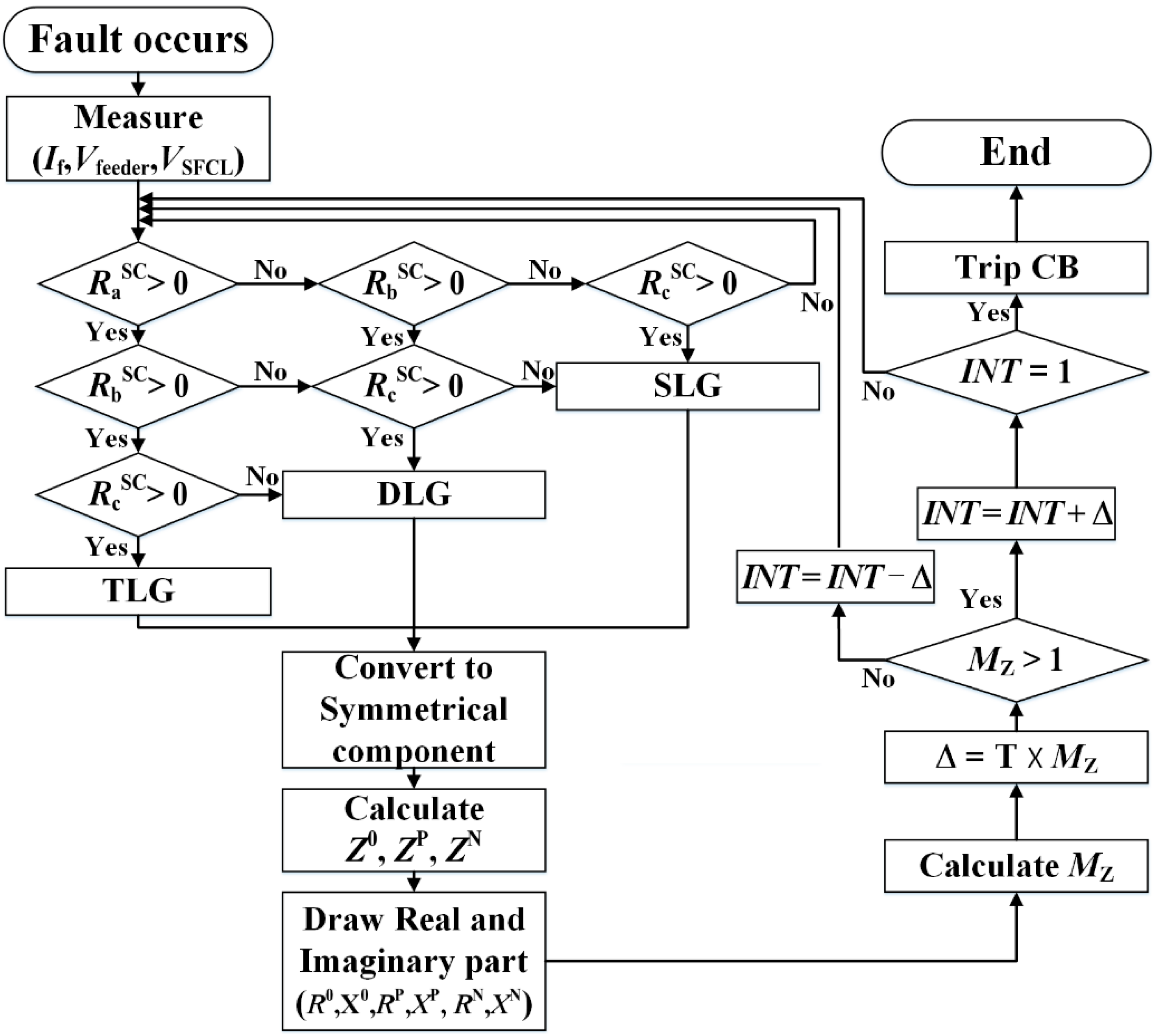
3.2. Over Current Relay’s Characteristic Modeling

The operation of the OCR is described by a characteristic equation with inverse characteristics shown in (10) to (12). TD is a time dial of the OCR, MI is an operation indicator value and A, B, and p are constants referred to KEPCO’s (Korea Electric Power Corporation) OCR Standard. MI is the ratio of feeder current (If) divided into setting current (Ipickup). If indicates the sum of the feeder current’s phasor sequence components and Ipickup is the pickup current considering rated voltage and line capacities. If the SFCL operates on the feeder, If is reduced and the trip time of OCR is delayed. The zero and negative sequences of the feeder current (If0, IfN) are zero at the triple line ground fault (TLG) [16,28].
T t r i p = T D ( A M p 1 + B )
M I = I f I p i c k u p
I f = | I f 0 + I f P + I f N |  
Therefore, the compensation method is needed to minimize the influence of the SFCL. (13) to (15) form the equations of the sequence impedance by reflecting the sequence feeder voltage (Vfeeder) and pickup voltage (Vpickup). The zero and negative sequences of the feeder voltage (V0feeder, VNfeeder) are zero at the triple-line ground fault (TLG).
M I V 0 = I f 0 I p i c k u p ( K V p i c k u p V f e e d e r 0 ) = K Z p i c k u p Z f e e d e r 0
M I V P = I f P I p i c k u p ( K V p i c k u p V f e e d e r P ) = K Z p i c k u p Z f e e d e r P
M I V N = I f N I p i c k u p ( K V p i c k u p V f e e d e r N ) = K Z p i c k u p Z f e e d e r N
(13) to (15) are converted into the reciprocals, then all reciprocal equations are added together and converted into the reciprocal again to make the sequence impedance Equation (16).
M I V = 1 1 M I V 0 + 1 M I V P + 1 M I V N = K Z p i c k u p Z f e e d e r 0 + Z f e e d e r P + Z f e e d e r N   = K Z p i c k u p | ( R f e e d e r 0 + j X f e e d e r 0 ) + ( R f e e d e r P + j X f e e d e r P ) + ( R f e e d e r N + j X f e e d e r N ) |
In (16), the sequence impedances of the SFCL should be eliminated from the feeder impedances to remove the effect of the SFCL from OCR’s trip operation. (17) is the impedance compensation method that the compensation constant K changes the result of (17) depending on the ground fault type. The parameters of OCR are described in Table 3.
M Z 0 P N = K Z p i c k u p | ( R f e e d e r 0 R S F C L 0 ) + j [ ( X f e e d e r 0 X S F C L 0 ) ] + ( R f e e d e r P R S F C L P ) + j [ ( X f e e d e r P X S F C L P ) ] + ( R f e e d e r N R S F C L N ) + j [ ( X f e e d e r N X S F C L N ) ] |
The flowchart of the impedance compensation method with the OCR operational algorithm is shown in Figure 3. The ground fault type is determined by measuring the resistance occurrence of HTSC element in each phase. After that, MZ is calculated using the sequence components of the feeder voltages, the SFCL voltages and the feeder currents. MZ is progressed with the operating characteristic of the OCR (10).

4. Results and Discussion

Fault current limiting of the over-current relay (OCR) using the impedance compensation method was analyzed from the simulation results in three types of ground fault. The fault simulations were performed in two OCR characteristic equations, which were the existing OCR algorithm (2) and the impedance compensation method (17). After that, the results with the SFCL were compared. In addition, three results of the impedance compensation method (17) were analyzed according to different K values (1, 2, and 3.5). Three types of ground faults were simulated in 0.3 [s] to analyze the results of the OCR’s operation.

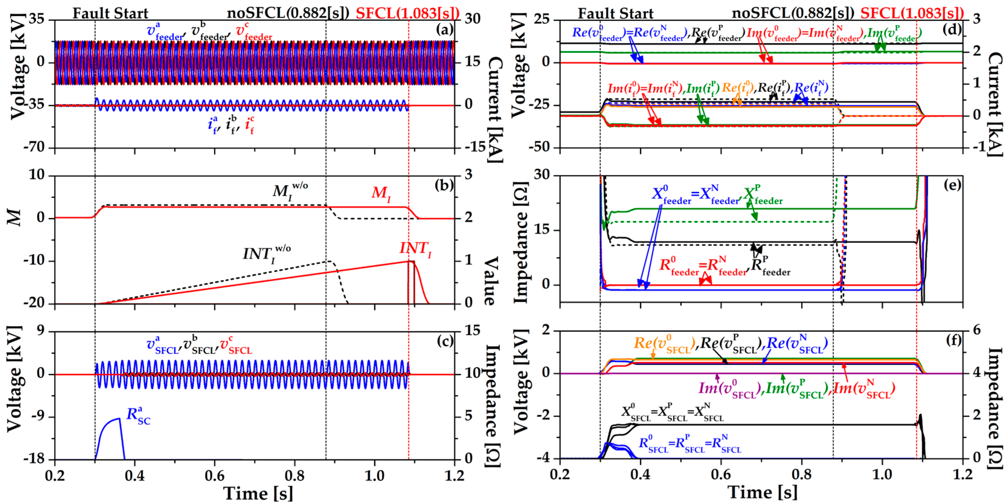
4.1. Single-Line Ground Fault

Figure 4 shows the single-line ground fault (SLG) in a phase to ground using the existing over-current relay (OCR) algorithm (2). OCR operates at 0.882 [s] without the SFCL and OCR with SFCL operates at 1.083 [s]. Figure 4a shows the feeder voltage and currents when the SFCL is installed. The operation of OCR using (2) is expressed in the integration value INTI, which increases after the fault occurs. The OCR is tripped when INTI approaches “1” point as seen in Figure 4b, which activates the CB to be open and separates the fault section from the main grid. In Figure 4c, the resistance of HTSC element (RaSC) obtains a resistance value because the fault current (If) exceeds the critical current. During the fault time, the voltage of the SFCL (vSFCL) is reduced by RaSC and increased again since the direction of the fault current changes to the current limiting reactor (CLR). Figure 4d shows the sequence component waveforms of the feeder voltages and currents. The dotted line is the feeder voltage and current using existing the OCR algorithm (2) without the SFCL and the solid line is the identical condition with the SFCL. The zero and negative sequence feeder voltages are almost the same. Figure 4e is the sequence component waveforms of the feeder impedances. The dotted line is the feeder impedances using the existing OCR algorithm (2) without the SFCL and the solid line is the identical condition with the SFCL. Figure 4f is the sequence component waveform of the SFCL voltages and impedances.
Figure 5 shows the single-line ground fault (SLG) in a phase to ground using the impedance compensation method (17). In Figure 5b, the operation of OCR using (17) is expressed in the integration value INTZ, which has three different waveforms depending on K values (1, 2, 3.5). When K = 3.5, the index value (MZ) and INTZ are most similar to the existing OCR algorithm (2) without SFCL (INTw/oI). OCR operates at 0.88 [s] and decreased by 0.002 [s] compared to the existing OCR algorithm (2) with SFCL. In Figure 5c, resistance of the HTSC element (RaSC) is the same as Figure 4 since the breaker operation of the SFCL is constant as the critical current (IC) is maintained. During the fault time, the voltage of the SFCL (vSFCL) is reduced by RaSC and increased again since the direction of the fault current changes to the current limiting reactor (CLR). Figure 5d shows the sequence components’ waveforms of the feeder voltages and currents. The dotted line is the feeder voltages and currents using existing OCR algorithm (2) without the SFCL and the solid line is the impedance compensation method (17) with the SFCL. The zero and negative sequence feeder voltages are almost the same. Figure 5e is the sequence components’ waveforms of feeder impedance. The dotted line is the feeder impedances using the existing OCR algorithm (2) without the SFCL and the solid line is the feeder impedances using the impedance compensation method (17) with the SFCL. Figure 5f is the sequence component waveforms of the SFCL voltages and impedances.

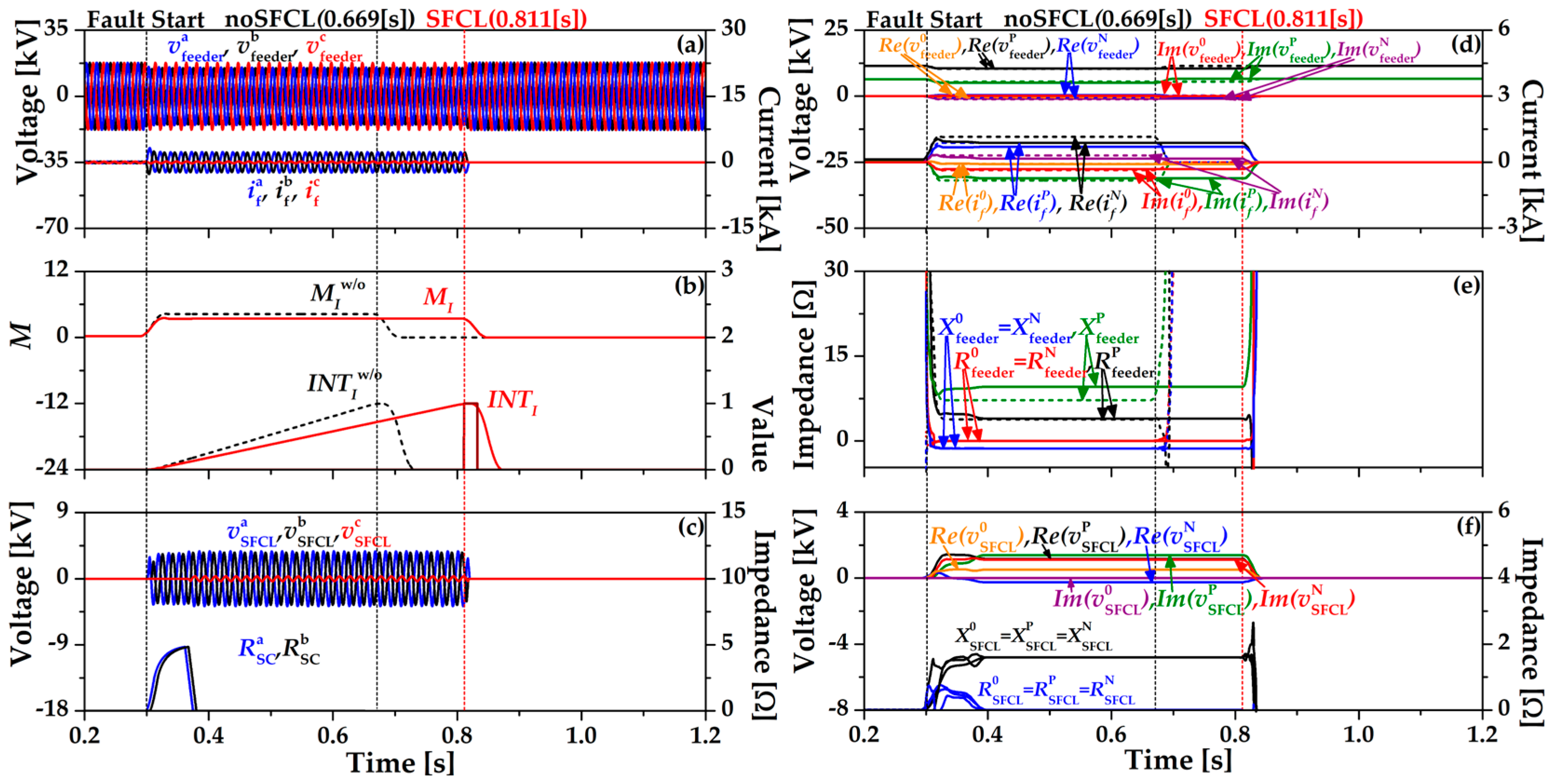
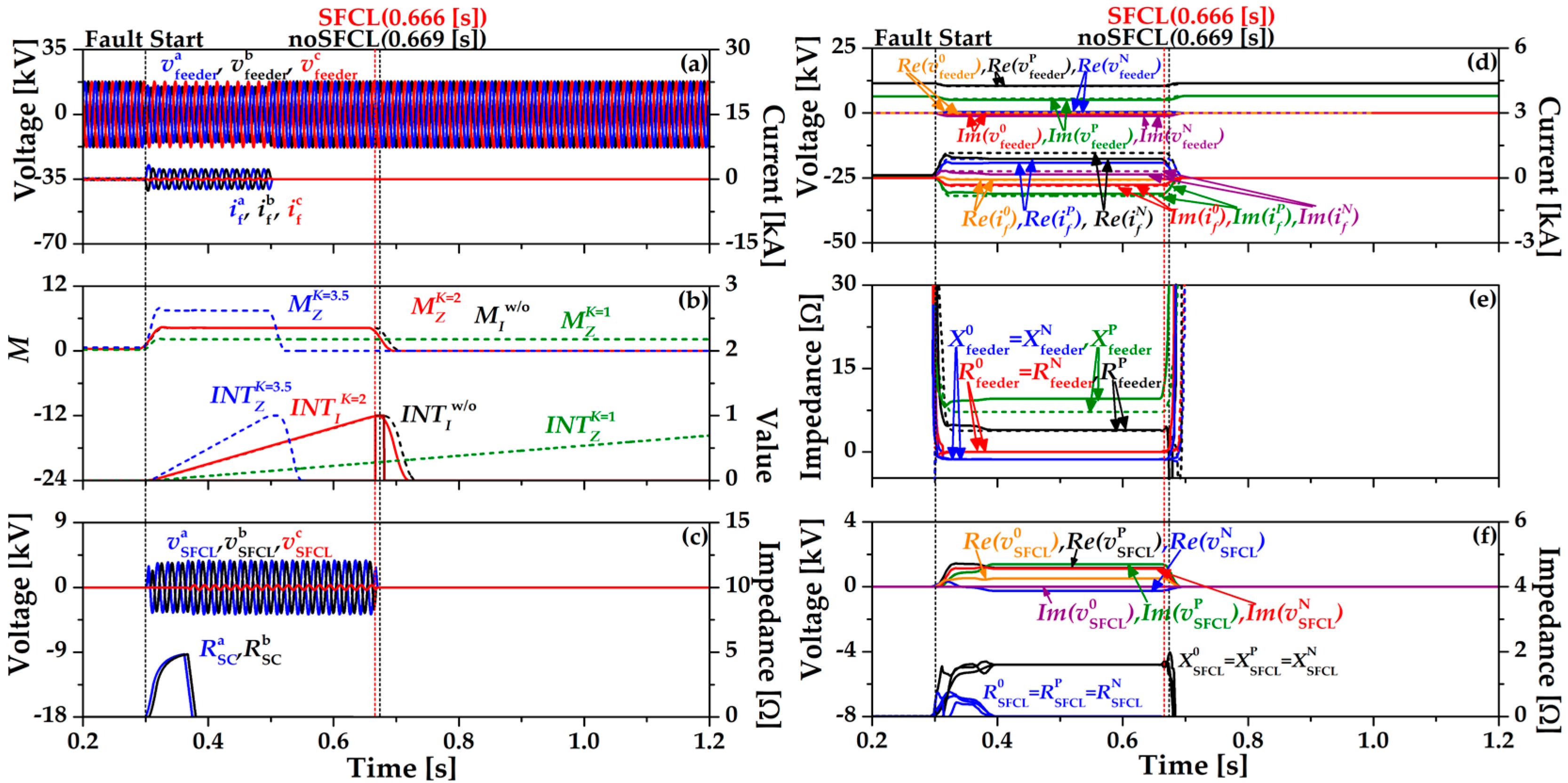
4.2. Double-Line Ground Fault

Figure 6 shows the double-line ground fault (DLG) in ab phase to ground using the existing over-current relay (OCR) algorithm (2). OCR operates at 0.669 [s] without the SFCL and OCR with SFCL operates at 0.811 [s]. Figure 6a shows the feeder voltages and currents when the SFCL is installed. The operation of OCR using (2) is expressed in the integration value INTI, which increases after the fault occurs and when INTI approaches “1” point as seen in Figure 6b. In Figure 6c, resistance of HTSC element (RaSC, RbSC) obtains a resistance value because the fault current (If) exceeds the critical current and RaSC, RbSC becomes zero when the breaker in the SFCL is operated, as explained in Section 2.2. During the fault time, the voltage of the SFCL (vSFCL) is reduced by RaSC and increased again since the direction of the fault current changes to the current limiting reactor (CLR). Figure 6d shows the sequence components’ waveforms of the feeder voltages and currents. The dotted line is the feeder voltages and currents using the existing OCR algorithm (2) without the SFCL and the solid line is the identical condition with the SFCL. The zero and negative sequence feeder voltages are almost the same. Figure 6e shows the sequence components’ waveforms of feeder impedances. The dotted line is the feeder impedances using the existing OCR algorithm (2) without the SFCL and the solid line is the identical condition with the SFCL. Figure 6f is the sequence component waveforms of the SFCL voltages and impedances.
Figure 7 shows the double-line ground fault (DLG) in ab phase to ground using impedance compensation method (17). In Figure 7b, the operation of OCR using (17) is expressed in the integration value INTZ, which has three different waveforms depending on the K value (1, 2, 3.5). When K = 2, index value (MZ) and INTZ are most similar to the existing OCR algorithm (2) without SFCL (INTw/oI). OCR operates at 0.666 [s] and decreased by 0.14 [s] compared to the existing OCR algorithm (2) with SFCL. In Figure 5c, the resistance of the HTSC element (RaSC, RbSC) is same with Figure 6 since the breaker operation is constant as the critical current (IC) is maintained. During the fault time, voltage of the SFCL (vSFCL) is reduced by RaSC, RbSC and increased again since the direction of the fault current changes to the current limiting reactor (CLR). Figure 7d shows the sequence components waveforms of the feeder voltages and currents. The dotted line is the feeder voltages and currents using the existing OCR algorithm (2) without the SFCL and the solid line is the impedance compensation method (17) with the SFCL. The zero and negative sequence voltages are almost the same. Figure 7e is the sequence components waveforms of feeder impedances. The dotted line is the feeder impedances using the existing OCR algorithm (2) without the SFCL and the solid line is the feeder impedances using the impedance compensation method (17) with the SFCL. Figure 7f is the sequence component waveforms of the SFCL voltages and impedances.

4.3. Triple-Line Ground Fault

Figure 8 shows the triple-line ground fault (TLG) using the existing over-current relay (OCR) algorithm (2). OCR operates at 0.627 [s] without the SFCL and OCR with SFCL operates at 0.757 [s]. Figure 8a shows the feeder voltages and currents when the SFCL is installed. The operation of OCR using (2) is expressed in the integration value INTI, which increases after the fault occurs and when INTI approaches “1” point as seen in Figure 8b. In Figure 8c, the HTSC element (RaSC, RbSC, RcSC) gets the resistance value because the fault current (If) exceeds the critical current and RaSC, RbSC, RcSC become zero when the breaker in the SFCL is operated, as explained in Section 2.2. During the fault time, the voltage of the SFCL (vSFCL) is reduced by RaSC, RbSC, RcSC and increased again since the direction of the fault current changes to the current limiting reactor (CLR). Figure 8d shows the sequence components waveforms of the feeder voltages and currents. The dotted line is the feeder voltages and currents using the existing OCR algorithm (2) without the SFCL and the solid line is the identical condition with the SFCL. Figure 8e is the sequence components’ waveforms of feeder impedances. The dotted line is the feeder impedances using existing the OCR algorithm (2) without the SFCL and the solid line is the identical condition with the SFCL. Figure 8f is the sequence component waveforms of the SFCL voltages and impedances. Unlike the results of the unbalanced faults (SLG, DLC), the zero and negative sequences are nonexistent.
Figure 9 shows the triple-line ground fault (TLG) using the impedance compensation method (17). In Figure 7b, the operation of OCR using (17) is expressed in the integration value INTZ, which has three different waveforms depending on the K value (1, 2, 3.5). When K = 1, index value (MZ) and INTZ are most similar to the existing OCR algorithm (2) without SFCL (INTw/oI). OCR operates at 0.626 [s] and decreased by 0.13 [s] compared to existing OCR algorithm (2) with SFCL. In Figure 9c, resistance of HTSC element (RaSC, RbSC, RcSC) is the same as Figure 6 since the breaker operation is constant since the critical current (IC) is maintained. During the fault time, voltage of the SFCL (vSFCL) is reduced by RaSC, RbSC, RcSC and increased again since the direction of the fault current changes to the current limiting reactor (CLR). Figure 9d shows the sequence components waveforms of the feeder voltages and currents. The dotted line is the feeder voltages and currents using the existing OCR algorithm (2) without the SFCL and the solid line is the impedance compensation method (17) with the SFCL. Figure 9e is the sequence components’ waveforms of feeder impedances. The dotted line is the feeder impedances using the existing OCR algorithm (2) without the SFCL and the solid line is the impedance compensation method (17) with the SFCL. Figure 9f is the sequence component waveforms of the SFCL voltages and impedances. Unlike the results of the unbalanced faults (SLG, DLC), the zero and negative sequences are nonexistent.

5. Discussion

The simulations are proposed in operation characteristics of OCR with SFCL depending on the three types of ground faults. In order to improve the trip delay of OCR, the existing OCR algorithm (2) changes into the impedance compensation method (17) by substituting the sequence components of a power distribution system. It is confirmed that the impedance compensation method improves the trip time delay of OCR in all ground fault types. Impedance compensation method (17) K should be set differently because the index value and trip time are different in three types of ground faults. Table 4 shows the proper K value, trip time of existing OCR algorithm and trip time of impedance compensation method according to the ground fault type.

6. Conclusions

The proper operation of OCR with SFCL is the impedance compensation method which has been introduced to improve the trip time delay of OCR in three types of ground faults. In case of the different fault types, the impedance compensation method is distinguished according to the compensation constant. The impedance components of the impedance compensation method are derived from voltages and currents of a power distribution system.
From the simulation results comparing the existing OCR algorithm and the impedance compensation method in three types of ground faults, the latter one improves the trip time delay of OCR due to the SFCL while the fault current is reduced. To apply to all types of ground fault, the compensation constant of the impedance compensation method should be changed.
In the future research, the protection coordination of OCRs using the impedance compensation method in unbalanced fault situation, considering dispersed generation in a power distribution system, will be studied with more elaborate compensation constants.

Author Contributions

Supervision, S.-H.L.; Writing—original draft, Y.-J.C.; Writing—review & editing, S.-H.L. All authors have read and agreed to the published version of the manuscript.

Funding

This work was supported by Korea Institute for Advancement of Technology (KIAT) grant funded by Korea Government(MOTIE) (P0017033, The Competency Development Program for Industry Specialist) and was also supported by the National Research Foundation of Korea (NRF) grant funded by the Korea government (MOE) (No. 2020R1F1A1077206).

Data Availability Statement

Data is contained within the article.

Conflicts of Interest

The authors declare no conflict of interest.

References

  1. Kim, H.J.; Yoon, T.A. Study on application of a high-speed trigger-type SFCL (TSFCL) for interconnection of power systems with different reliabilities. IEEE Trans. Appl. Supercond. 2010, 20, 1194–1198. [Google Scholar] [CrossRef]
  2. Song, M.; Tang, Y.; Zhou, Y.; Ren, L.; Chen, L.; Cheng, S. Electromagnetic Characteristics Analysis of Air-Core Transformer Used in Voltage Compensation Type Active SFCL. IEEE Trans. Appl. Supercond. 2010, 20, 1194–1198. [Google Scholar] [CrossRef]
  3. Zou, Z.-C.; Chen, X.-Y.; Li, C.-S.; Xiao, X.Y.; Zhang, Y. Conceptual Design and Evaluation of a Resistive-Type SFCL for Efficient Fault Ride through in a DFIG. IEEE Trans. Appl. Supercond. 2016, 26, 7. [Google Scholar] [CrossRef]
  4. Lim, S.H.; Han, T.H.; Cho, Y.S.; Choi, H.S.; Han, B.S.; Lee, S.W. Quench characteristics of HTSC elements in integrated three-phase flux-lock type SFCL according to ground-fault types. Phys. C Supercond. Appl. 2007, 463, 1198–1203. [Google Scholar] [CrossRef]
  5. Hyun, O.-B.; Park, K.-B.; Sim, J.; Kim, H.-R.; Yim, S.-W.; Oh, I.-S. Introduction of a Hybrid SFCL in KEPCO Grid and Local Points at Issue. IEEE Trans. Appl. Supercond. 2009, 19, 1946–1949. [Google Scholar] [CrossRef]
  6. Shirai, Y.; Noda, S.; Yamabe, K.; Hattori, K.; Baba, J.; Nishihara, T.; Nitta, T.; Kobayashi, S.; Sato, K. Current Limiting Performance of Three-Phase Concentric Transformer Type SFCL at Unbalanced Fault Conditions. IEEE Trans. Appl. Supercond. 2012, 23, 5601905. [Google Scholar] [CrossRef] [Green Version]
  7. Kim, W.-S.; Hyun, O.-B.; Park, C.-R.; Yim, S.-W.; Yu, S.-D.; Yang, S.-E.; Kim, H.-S.; Kim, H.R. Dynamic Characteristics of a 22.9 kV Hybrid SFCL for Short-Circuit Test Considering a Simple Coordination of Protection System in Distribution Networks. IEEE Trans. Appl. Supercond. 2012, 22, 3. [Google Scholar]
  8. Sung, B.C.; Park, D.K.; Park, J.W.; Ko, T.K. Study on a Series Resistive SFCL to Improve Power System Transient Stability: Modeling, Simulation, and Experimental Verification. IEEE Trans. Ind. Electron. 2009, 56, 2412–2419. [Google Scholar] [CrossRef]
  9. Shen, B.; Chen, Y.; Li, C.; Wang, S.; Chen, X. Superconducting fault current limiter (SFCL): Experiment and the simulation from finite-element method (FEM) to power/energy system software. Energies 2021, 234, 1. [Google Scholar] [CrossRef]
  10. Huh, J.-S.; Shin, H.-S.; Moon, W.-S.; Kang, B.-W.; Kim, J.-C. Study on Voltage Unbalance Improvement Using SFCL in Power Feed Network with Electric Railway System. IEEE Trans. Appl. Supercond. 2013, 23, 3601004. [Google Scholar]
  11. Choi, H.-Y.; Cho, Y.-S.; Jung, B.-I.; Chung, D.-C.; Fathy, A. Comparison of the Unbalanced Faults in Three-Phase Resistive and Matrix-Type SFCLs. IEEE Trans. Appl. Supercond. 2010, 20, 1215–1218. [Google Scholar] [CrossRef]
  12. Lim, S.-H.; Lim, S.-T. Current Limiting and Recovery Characteristics of a Trigger-Type SFCL Using Double Quench. IEEE Trans. Appl. Supercond. 2018, 28, 17572499. [Google Scholar] [CrossRef]
  13. Martini, L.; Bocchi, M.; Angeli, G.; Ascade, M.; Rossi, V.; Valzasina, A.; Ravetta, C.; Fratti, S.; Martino, E. Live grid field-testing final results of the first Italian superconducting fault current limiter and severe 3-phase fault experience. IEEE. Trans. Appl. Supercond. 2015, 25, 3. [Google Scholar] [CrossRef]
  14. Shin, J.W.; Kim, J.C.; Lee, H.; Yoon, K.H.; Chai, H.S.; Kim, J.S. Impact of SFCL according to Voltage Sags Based Reliability. IEEE Trans. Appl. Supercond. 2021, 31, 5. [Google Scholar] [CrossRef]
  15. Lim, S.T.; Lim, S.H. Analysis on operational improvement of OCR using voltage component in a power distribution system for application of SFCL. J. Electr. Eng. Technol. 2019, 14, 1027–1033. [Google Scholar] [CrossRef]
  16. Park, M.-K.; Lim, S.-H. Impedance Compensation Method of Protective Relay for SFCL’s Application in a Power Distribution System. IEEE Trans. Appl. Supercond. 2021, 31, 20463141. [Google Scholar] [CrossRef]
  17. Park, M.-K.; Lim, S.-H. Analysis on Protection Coordination of OCRs Using Voltage Components for the Application of SFCL in a Power Distribution System with DG. IEEE Trans. Appl. Supercond. 2021, 31, 20994711. [Google Scholar]
  18. Moon, J.; Lim, S.; Kim, J.; Yun, S. Assessment of the Impact of SFCL on Voltage Sags in Power Distribution System. IEEE Trans. Appl. Supercond. 2011, 21, 2161–2164. [Google Scholar] [CrossRef]
  19. Lim, S.T.; Lim, S.H. Analysis on protective coordination between over-current relays with voltage component in a power distribution system with SFCL. IEEE Trans. Appl. Supercond. 2020, 30, 4. [Google Scholar] [CrossRef]
  20. Choi, S.-J.; Lim, S.H. Enhancement on the Fault Ride through Capability of Power Distribution Systems Linked by Distributed Generation due to the Impedance of Superconducting Fault Current Limiters. Energies 2019, 12, 4810. [Google Scholar] [CrossRef] [Green Version]
  21. Lim, S.T.; Lim, S.H. Study on improvement of overcurrent relay (OCR)’s operation due to application of superconducting fault current limiter (SFCL) in power distribution system with a dispersed generation. Trans. Korean Inst. Electr. Eng. 2017, 66, 300–304. [Google Scholar] [CrossRef] [Green Version]
  22. Mangunkusumo, K.G.H.; Kusuma, A.A.; Munir, B.S. A Case Study of Mutual Impedance Effect in Parallel Transmission Lines Under Maintenance Condition. In Proceedings of the 2018 10th International Conference on Information Technology and Electrical Engineering (ICITEE), Bali, Indonesia, 24–26 July 2018; pp. 192–195. [Google Scholar]
  23. Koirala, A.; D’hulst, R.; van Hertem, D. Impedance modelling for European style Distribution Feeder. In Proceedings of the 2019 International Conference on Smart Energy Systems and Technologies (SEST), Porto, Portugal, 11 September 2019. [Google Scholar]
  24. Wen, B.; Burgos, R.; Boroyevich, D.; Mattavelli, P.; Shen, Z. AC Stability Analysis and dq Frame Impedance Specifications in Power-Electronics-Based Distributed Power Systems. IEEE J. Emerg. Sel. Top. Power Electron. 2017, 5, 1455–1465. [Google Scholar] [CrossRef]
  25. Saadat, H. Power System Analysis; Milwaukee School of Engineering: Milwaukee, WI, USA, 1999. [Google Scholar]
  26. Sravya, A.S.L.; Yoshita, L.N.; Reddy, B.D.D.; Sailaja, V.; Manitha, P.V.; Deepa, K. Impedance Bus Matrix Formation using Bus Building Algorithm for Power System Analysis. In Proceedings of the 2020 IEEE International Women in Engineering (WIE) Conference on Electrical and Computer Engineering (WIECON-ECE), Bhubaneswar, India, 26–27 December 2020; pp. 200–205. [Google Scholar]
  27. Paz, M.C.R.; Ferraz, R.G.; Bretas, A.S.; Leborgne, R.C. System unbalance and fault impedance effect on faulted distribution networks. Comput. Math. Appl. 2010, 60, 1105–1114. [Google Scholar]
  28. Korea Electric Power Corporation. Distribution Practical III; Korea Electric Power Corporation: Seoul, Korea, 2006. [Google Scholar]
Figure 1. Structure of power distribution system with superconducting fault current limiter (SFCL).
Energies 15 07405 g001
Figure 2. Configuration of trigger type SFCL.
Energies 15 07405 g002
Figure 3. OCR operational algorithm flowchart.
Energies 15 07405 g003
Figure 4. Waveforms and signals of OCR using MI in SLG. (a) Three phase feeder voltage (vfeeder), current (if). (b) Index of CB (MI) and signal of OCR (INTI). (c) Three phase SFCL voltage (vSFCL), HTSC element (RaSC). (d) Sequence feeder voltages (v0feeder, vPfeeder, vNfeeder), sequence feeder currents (i0f, iPf, iNf). (e) Sequence feeder impedances (R0feeder, RPfeeder, RNfeeder, X0feeder, XPfeeder, XNfeeder). (f) Sequence SFCL voltages (v0SFCL, vPSFCL, vNSFCL) and sequence SFCL impedances (R0SFCL, RPSFCL, RNSFCL, X0SFCL, XPSFCL, XNSFCL).
Energies 15 07405 g004
Figure 5. Waveforms and signals of OCR using MI, MZ in SLG. (a) Three phase feeder voltage (vfeeder), current (if). (b) Index of CB (MI, MZ) and signal of OCR (INTI, INTZ). (c) Three phase SFCL voltage (vSFCL), HTSC element (RaSC). (d) Sequence feeder voltages (v0feeder, vPfeeder, vNfeeder), sequence feeder currents (i0f, iPf, iNf). (e) Sequence feeder impedances (R0feeder, RPfeeder, RNfeeder, X0feeder, XPfeeder, XNfeeder). (f) Sequence SFCL voltages (v0SFCL, vPSFCL, vNSFCL) and sequence SFCL impedances (R0SFCL, RPSFCL, RNSFCL, X0SFCL, XPSFCL, XNSFCL).
Energies 15 07405 g005
Figure 6. Waveforms and signals of OCR using MI in DLG. (a) Three phase feeder voltage (vfeeder), current (if). (b) Index of CB (MI) and signal of OCR (INTI). (c) Three phase SFCL voltage (vSFCL), HTSC element (RaSC, RbSC). (d) Sequence feeder voltages (v0feeder, vPfeeder, vNfeeder), sequence feeder currents (i0f, iPf, iNf). (e) Sequence feeder impedances (R0feeder, RPfeeder, RNfeeder, X0feeder, XPfeeder, XNfeeder). (f) Sequence SFCL voltages (v0SFCL, vPSFCL, vNSFCL) and sequence SFCL impedances (R0SFCL, RPSFCL, RNSFCL, X0SFCL, XPSFCL, XNSFCL).
Energies 15 07405 g006
Figure 7. Waveforms and signals of OCR using MI, MZ in DLG. (a) Three phase feeder voltage (vfeeder), current (if). (b) Index of CB (MI, MZ) and signal of OCR (INTI, INTZ). (c) Three phase SFCL voltage (vSFCL), HTSC element (RaSC, RbSC). (d) Sequence feeder voltages (v0feeder, vPfeeder, vNfeeder), sequence feeder currents (i0f, iPf, iNf). (e) Sequence feeder impedances (R0feeder, RPfeeder, RNfeeder, X0feeder, XPfeeder, XNfeeder). (f) Sequence SFCL voltages (v0SFCL, vPSFCL, vNSFCL) and sequence SFCL impedances (R0SFCL, RPSFCL, RNSFCL, X0SFCL, XPSFCL, XNSFCL).
Energies 15 07405 g007
Figure 8. Waveforms and signals of OCR using MI in TLG. (a) Three phase feeder voltage (vfeeder), current (if). (b) Index of CB (MI) and signal of OCR (INTI). (c) Three phase SFCL voltage (vSFCL), HTSC element (RaSC, RbSC, RcSC). (d) Positive sequence feeder voltage (vPfeeder), positive sequence feeder current (iPf). (e) Sequence feeder impedances (RPfeeder, XPfeeder). (f) Positive sequence SFCL voltage (vPSFCL) and positive SFCL impedance (RPSFCL, XPSFCL).
Energies 15 07405 g008
Figure 9. Waveforms and signals of OCR using MI, MZ in TLG. (a) Three phase feeder voltage (vfeeder), current (if). (b) Index of CB (MI, MZ) and signal of OCR (INTI, INTZ). (c) Three phase SFCL voltage (vSFCL), HTSC element (RaSC, RbSC, RcSC). (d) Positive sequence feeder voltage (vPfeeder), positive sequence feeder current (iPf). (e) Positive sequence feeder impedance (RPfeeder, XPfeeder). (f) Positive sequence SFCL voltage (vPSFCL) and positive sequence SFCL impedance (RPSFCL, XPSFCL).
Energies 15 07405 g009
Table 1. Specifications of Power Distribution System.
Experimental CircuitValueUnit
Source154[kV]
100[MVA]
MTR154/22.9[kV]
60[MVA]
Line ImpedanceZP = ZN = 0.182 + j0.391[Ω/km]
Z0 = 0.518 + j1.189[Ω/km]
Feeder Length10[km]
Load5[MW]
PF = 0.95
Table 2. Parameters of trigger type SFCL.
ParametersValueUnit
VSet1[kV]
ISet0.5[kA]
HTSCConvergence resistance (Rn) = 5
Critical current (IC) = 1
[Ω]
[kA]
CLRj1.6[Ω]
Table 3. Parameters of OCR.
ParametersData
TD0.1
A39.85
B1.084
p1.95
V p i c k u p [kV]10.56
I p i c k u p [kA]0.504
Table 4. Simulation result by fault type.
Fault TypeKExisting OCR Algorithm [s]Impedance Compensation Method [s]
SLG3.50.8820.88
DLG20.6690.666
TLG10.6270.626
Publisher’s Note: MDPI stays neutral with regard to jurisdictional claims in published maps and institutional affiliations.

