Article

Dynamic Grid Voltage-Based Impedance-Reshaped Control for the Stability Enhancement of Grid-Connected DC/AC Converter System under Bidirectional Power Flow

1
Zhoushan Power Supply Company State Grid Zhejiang Electric Power Ltd., Zhoushan 316000, China
2
Department of Electrical Engineering, North China Electric Power University, Baoding 071003, China
*
Author to whom correspondence should be addressed.
Energies 2022, 15(19), 7269; https://doi.org/10.3390/en15197269
Submission received: 25 July 2022 / Revised: 29 September 2022 / Accepted: 29 September 2022 / Published: 3 October 2022
(This article belongs to the Section F3: Power Electronics)

Abstract

:
Considering the bidirectional three-phase DC/AC converter, it presents different impedance characteristics on AC side under different power flow directions, resulting in different stability margin. This may cause the system instability at high-power level. This directionally oriented stability difference has not been paid enough attention in the grid-connected converter control. To mitigate the stability variations under bidirectional power flow, a dynamic grid voltage-based impedance reshaping control is proposed in this paper. The proposed method extracts the grid voltage dynamic component, and correspondingly compensates the power output, which is capable of regulating the power output coordinated with voltage dynamics in both power flow directions, neutralizing the stability difference and enhancing the bidirectional power flow stability. Unlike the conventional unidirectional damping optimization control in the current loop, the proposed control method can maintain satisfied stability under bidirectional power flow through the grid side voltage, which can avoid increasing the current loop delay, and thus endow the converter flexible bidirectional power process capability. The effectiveness of the proposed method has been verified by both simulations and experiments.

1. Introduction

With the intensification of energy crisis and increasing of power demand, more and more renewable energy-based generation units, such as the solar power generations and wind power turbines, have been integrated into the power systems [1,2]. Power converters have been widely used as the interface between distributed power sources and the power grid. In the AC-DC hybrid power networks, such as the flexible DC power transmission and DC microgrids, DC bus and the AC bus, are interconnected by the bidirectional converter, and then the bidirectional power flow capability becomes essential [3]. Figure 1 shows the bidirectional grid-connected converter. As shown, when there is excess energy in the DC bus, the excessive energy will be transferred to the AC grid through the bidirectional converter, named the forward power flow mode. When the distributed power supply of the DC system cannot meet the local load demand, the inadequate electric energy is transferred from the AC to DC side, named as a reverse or backward power flow. The grid-connected bidirectional converter is responsible for not only interconnecting the DC and AC network, but also for stabilizing both side networks [4]. Different power flow directions (DC to AC or AC to DC) and power levels will have different effects on system stability [5]. Thus, it is necessary to analyze and solve the bidirectional stability difference problem.
Currently, the state-space method and impedance-based method are the widely applied methods to analyze the stability of grid-connected converter system [6]. Generally, the impedance-based method is simpler, because only sub-system impedance models are needed, and then the impedance-based stability criterion is utilized for stability evaluation [7,8]. The d-q impedance modelling method is used to establish the impedance model in a synchronous reference frame, and small-signal linearization around the static operating point is also involved [9,10].
When the power flows from the AC to DC side, under conventional power dispatching control, the converter is performing as a constant power load (CPL) in the grid system [11]. The converter negative input impedance will, in turn, have a higher tendency to destabilize the system [12]. The problem will inevitably be complex under the bidirectional power flow, because the continuous power reversal will vary the converter impedance from negative to positive values, reducing the capacity of bidirectional power transmission [13]. Conventionally, the virtual impedance-reshaped methods are developed to solve the negative impedance issues on the DC side [14,15]. In [16], an improved virtual impedance control strategy is proposed, which changes the DC output impedance of the DC voltage control converter to improve the transmission capacity of the system but does not solve the problem of negative impedance from the impedance characteristics. In [17], for the cascaded converter system, the output impedance of the DC bus voltage controlling converter and the input impedance of the constant power control converter are reshaped. However, only the DC side impedance under the bidirectional power flow is studied. Therefore, this paper focuses on the AC side converter impedance under bidirectional power flow.
The optimization of the AC side impedance is a supplement to the converter AC side stability. Regarding this point, in [18], an implementation is given to damp the sub-synchronous resonance for the rectifier AC side. In [19], an impedance controller was proposed to reshape the q-axis impedance to a positive resistance in the low frequency. In [9], a feedforward control method was proposed to compensate the PLL disturbance to correct the output impedance of the AC side of the converter. The majority of the literature focuses on the negative impedance in unidirectional power flow and lacks a detailed analysis of the bidirectional stability difference caused by the variation of impedance characteristics on the converter AC side. In [20], the instability mechanism of the converter under different working conditions is studied, and it is proposed to reduce the parameter value on the positive feedback path to improve the stability of the converter, but the research on the full impedance characteristic of the converter is lacking. Generally, the literature mostly focuses on the negative impedance of the AC side under unidirectional power flow, and the bidirectional stability difference has not been well noticed.
Thus, this paper digs into the bidirectional converter impedance-based stability on the AC side. A dynamic voltage-based impedance reshaping control is proposed in this paper, which aims to improve bidirectional stability performance on AC side. The proposed method extracts the AC grid voltage transient component to dynamically compensate the power output, which contributes to the bidirectional converter presenting a similar impedance; thus, the converter AC side behaves as well damped in both the forward and reversed power flow. Since the voltage dynamic component is utilized to compensate the power output, conventional virtual impedance solutions apply the feedback current signal to mimic the series resistance through a virtual impedance coefficient, which may reduce the dynamic response speed of current control loop and increase the time delay. While in the proposed control, the impedance reshaping signal is extracted from grid voltage, and correspondingly varies the current reference, which can avoid the interference to current control loop, presenting a better current loop performance.
This paper is organized as follows: Section 2 presents the impedance modelling, and Section 3 presents the details of the proposed bidirectional impedance reshaping control. Section 4 shows the simulation and experiment results. Finally, Section 5 summarizes the conclusions.

2. Impedance Modeling and Stability Analysis of Grid-Connected DC/AC Converter System under Conventional Control

2.1. Topology and Control of Grid-Connected Converter System

Figure 2 shows the topology and conventional control of grid-connected converter system. As in Figure 2a, Udc represents DC-side voltage; C represents DC-side capacitance; ea, eb and ec are mid-point voltages of converter; ia, ib and ic are AC-side three-phase grid-connected currents; ua, ub and uc are AC-side grid-connected-point voltages; Lf and Rf are filter inductance and resistance, respectively; Lg and Rg are equivalent line inductance and resistance of AC grid, respectively. In grid-connected converter system, due to the practical working condition, the power flow is bidirectional, such as the interface DC/AC converter in DC/AC hybrid networks. Specifically, the power flow direction from the DC side to the AC grid is specified as the forward direction. Contrarily, the direction from the AC grid to the DC side is recognized as a reversed power flow.
Figure 2b is the control block diagram of conventional constant power mode, which is used to adjust power level and flow direction, and there is no power outer-loop. In the d-q rotation reference frame, the power can be calculated as
P = 1.5 u d i d + u q i q Q = 1.5 u d i q u q i d
where ud and uq are the grid-connected-point voltages on the d-axis and q-axis, respectively. id and iq are the grid-connected currents on d-axis and q-axis, respectively. If the d-axis voltage is oriented along the AC grid voltage vector position, then uq is 0, and the grid-connected current references can be expressed as
i d * = 2 P * / 3 u d i q * = 2 Q * / 3 u q
where P* and Q* are active and reactive power references, respectively; id* and iq* are current references on the d-axis and q-axis, respectively.
The current inner-loop adopts PI controller, which can be expressed as follows.
G i s = K pi + K ii / s
where Kpi and Kii are the proportional coefficient and integral coefficients, respectively.

2.2. Impedance Modeling of Grid-Connected Converter under Conventional Control

Small-signal models of converter impedance under current and power dispatching control in single power flow direction can be obtained in [9]. By following this derivation process, the output and input impedance model of converter under direct power control can be derived, respectively. The output impedance under the forward power flow is modelled first.
The output impedance small-signal model is shown in Figure 3. The influence of Phase-Locked Loop (PLL) is considered in the d-q frame. In a steady state, the system d-q frame and controller d-q frame can coincide with each other. The PLL dynamics give rise to the angle difference between the two d-q frames when the grid voltage is disturbed by externals. The variable, in the system d-q frame and controller d-q frame, can be represented with the superscript s and c, respectively [11].
In the system d-q frame, A1 is the transfer function matrix from duty ratio perturbation Δds to grid current perturbation Δis, shown as
A 1 = U dc L f s + R f 2 + ω g L f 2 L f s + R f ω g L f ω g L f L f s + R f
A2 is the open-loop output impedance matrix without PLL, from voltage perturbation Δus to grid current perturbation Δis, and its expression is
A 2 = Z d d Z d q Z q d Z q q = L f s + R f ω g L f ω g L f L f s + R f
In the controller d-q frame, A3, A4 and A5 are the small-signal transfer function from the actual AC grid voltage to the controller grid voltage, the controller grid current and the controller duty ratio in the d-q frame, respectively, shown as
A 3 = 0 i q s G PLL s 0 i d s G PLL s
A 4 = 1 u q s G PLL s 0 1 u d s G PLL s
A 5 = 0 D q s G PLL s 0 D d s G PLL s
where Dds and Dqs are the duty ratio on d-axis and q-axis, respectively; GPLL(s) is the transfer function of PLL small-signal model, as:
G PLL s = G pll s s + U g d s G pll s
where Gpll(s) is the expression of the PLL regulator, Gpll(s) = Kppll + Kipll/s.
A6 is the matrix of active and reactive power.
A 6 = P * Q * Q * P *
The constant expression C1 = −2/(3Ud2), and Ud is the average value of the grid voltage under steady state, which is 311 in this paper.
A7 represents the decoupling term.
A 7 = 0 2 ω g L f / U dc 2 ω g L f / U dc 0
A8 is current inner-loop controller matrix.
A 8 = G i s 0 0 G i s
From Figure 3, considering the effects of PLL and conventional direct power control, the converter output impedance matrix for forward power flow can be derived as
Z out = I + A 1 A 8 A 7 A 2 1 + A 1 C 1 A 6 A 4 A 8 + A 3 A 8 A 7 A 5
Under forward power flow, the converter is performing as a constant power source (CPS). However, the converter is simplified to CPL when the power flows along the reverse direction [21]. Similar to the output impedance modelling under forward power flow, the input impedance small-signal model can be obtained and is shown in Figure 4.
From Figure 4, the converter input impedance matrix for reverse power flow can be derived as
Z in = I + A 1 A 8 A 7 A 2 1 + A 1 C 1 A 6 A 4 A 8 + A 3 A 7 A 8 + A 5
According to Equations (13) and (14), the Bode diagrams of converter output and input impedance as power increases can be plotted and are shown in Figure 5, which can then be used for analyzing the converter bidirectional impedance characteristic differences.
As obviously seen, the magnitude of Zdd and Zqq is far larger than the magnitude of Zdq and Zqd, so Zdq and Zqd can be negligible [22]. After decoupling, the d-d impedance component and q-q component regulate the active power and reactive power independently. In high-power factor AC scenarios, the system stability is mainly determined by the d-d impedance component [23,24]. Therefore, the d-d impedance component is used to investigate the impedance characteristics and AC side stability in the following theoretical analysis. From Figure 5a, the phase of Zdd is closed to 0° at low frequency, which means the output impedance under forward power flow is a positive damping characteristic and can be simplified to a positive resistance (+R). Moreover, from Figure 5b, the phase of Zdd is close to 180° at low frequency, which means the input impedance in reverse direction is a negative damping characteristic and can be roughly simplified to a negative resistance (−R). Besides, as power increases, the magnitude of Zdd at low frequency reduces, and its negative damping region becomes wider, since the input impedance can be seen as a CPL.

2.3. Impedance Interaction with Conventional Direct Power Control

The grid-connected converter and AC grid are interconnected by the long transmission lines and isolated transformers [4]. Therefore, the grid equivalent grid impedance can be taken as a series of connected inductors and resistors [25]. In the d-q frame, the impedance matrix Zg can be expressed as [26]
Z g = Z g d d Z g d q Z g q d Z g q q = L g s + R g ω g L g ω g L g L g s + R g
where ωg is AC gird voltage angular frequency.
Figure 6 shows the Thevenin Norton equivalent circuit of bidirectional grid-connected converter system under conventional direct power control. Based on the generalized Nyquist criterion [27,28], the d-d impedance component of system minor loop gain Tmdd can be defined as Equation (16).
T m d d = Z g d d Z out - d d = Z g d d Z in - d d
where Zout-dd and Zin-dd are the d-d impedance components of the output and input impedance of the converter, respectively.
Based on the minor loop gain and the established converter impedance model, the Nyquist plots at a low-power level (0.5 and 1.5 kW) and relative high-power level (10, 20 and 30 kW) under the forward power flow are shown in Figure 7a. Besides, the Nyquist plots of reverse direction are shown in Figure 7b.
Firstly, comparing Figure 7a,b, at the low-power level, the gain margin (GM) in the forward power direction is larger than that in the reverse power direction. Moreover, at the high-power level, the Nyquist plots are noted to move away from (−1, j0) as the power increases when the power flows along the forward direction. That means the system can still remain stable under positive damping. However, the Nyquist plots, in the reverse power direction, are noted to move closer to (−1, j0) as the power increases. That means the system stability is gradually compromised and becomes unstable owing to the negative impedance.
To sum up, at the low-power level, there is gain margin difference between the forward and reverse power flow. At the high-power level, there is stability difference between the two power directions. Therefore, the impedance-reshaped stability-enhancing control is needed to eliminate the influence of negative impedance, thus improving the system power transmission capacity under bidirectional power flow.

3. Impedance-Reshaped Stability-Enhancing Control

3.1. Impedance-Reshaped Stability-Enhancing Control

Since the negative impedance exists when the converter is operating as a constant power load, the changing trends of voltage and current are opposite [15]. In order to turn negative impedance into positive impedance for the converter, a conventional impedance-reshaped control strategy is developed as shown in Figure 8a. In [29], the output impedance is shaped to an impedance with ideal characteristics by independently designing the current control loop and virtual impedance parameter design. However, this virtual impedance control will increase the time delay of current control loop, thus reducing the stability margin. Therefore, this paper presents the stability-enhancing (IRSE) control, and the control scheme is shown in Figure 8b.
From Figure 8b, a second-order low-pass filter (LPF) is applied in the extraction of grid voltage perturbation. Then, the voltage perturbation ud~ is added to the active power references after passing through an impedance controller. The principle of proposed control is to reflect the voltage disturbance on the active power, so that the changing trends of voltage and current can be kept the same, causing the negative impedance to be reshaped to a positive impedance and enhancing the system stability.
As in Figure 8, the voltage perturbation ud~ is derived as
u d ~ = 1 G LPF s u d = G u s u d
where GLPF(s) is the transfer function of second-order low-pass filter, and Gu(s) is the transfer function of voltage perturbation extraction.
G u s = s 2 + 2 ζ ω n s s 2 + 2 ζ ω n s + ω n 2
where ωn is the undamped natural frequency, ωn = 2πfc; fc is the filter cutoff frequency; and ζ is the damping ratio, generally ζ = 0.707.
The cutoff frequency fc is related to the system stability and dynamic performance. Specifically, if fc is too high, the extraction process of voltage perturbation is not sufficient, which means the effect of the proposed control is relatively poor. If fc is too low, however, the dynamic performance will be severely affected. After comprehensive consideration, the cutoff frequency fc is designed as 50 Hz in this paper.
The input of the impedance controller is ud~, and the output is added to P*. In order to make the output of the impedance controller 0 in the steady state (zero output) and compensate only during transient, it is designed as a P controller rather than a PI controller. The impedance controller Gz(s) can be expressed as
G z s = K pz
From Figure 8, after introducing the IRSE control, the active power reference satisfies the following equation
G z s u d ~ + P * = 1.5 u d i d *
Substituting Equation (17) into Equation (20), linearizing Equation (20) around the steady-state value and ignoring the second-order perturbations, the small-signal equation can be written as
G z s G u s Δ u d = 1.5 Δ u d I d * + 1.5 U d Δ i d *
According to Equation (21), the relationship between Δud and Δid* is obtained as follows.
Δ u d Δ i d * = 1.5 U d 1.5 I d * + G z s G u s
The input impedance under IRSE control can be equivalently expressed as follows.
Z in , eq = Δ u d Δ i d Δ u d Δ i d * = 1 1 Z in - d d + 1 Z IRSE
Define ZIRES as
Z IRSE = 1.5 U d G z s G u s
Thus, the equivalent circuit under IRSE control in reverse power direction can be obtained and is shown in Figure 9. On the basis of the original impedance, a novel positive impedance is connected in parallel.
Aiming at reshaping the negative impedance to positive impedance in the reverse power direction, the first requirement is to make Gu(s)Gu(s) > 1.5Id*, according to Equation (22). Moreover, the second requirement is to increase the magnitude of the reverse impedance. That means Gz(s)Gu(s) cannot be set too large. After comprehensive consideration, the proportional coefficient Kpz of the impedance controller is designed as 3 Id* in this paper.

3.2. Impedance Modelling with Proposed Control

According to Equations (2) and (21), the current perturbation matrix can be derived as
Δ i d * Δ i q * = 2 3 1 U d 2 P * Q * Q * P * Δ u d Δ u q + 2 3 1 U d G z s G u s 0 0 0 Δ u d Δ u q
Equation (25) can be simplified as
Δ i * c = C 1 A 6 Δ u c + C 2 A 9 Δ u c
Define matrix A9 as
A 9 = G z s G u s 0 0 0
According to Equation (26), based on Figure 3 and Figure 4, the small-signal block diagram under IRSE control can be obtained and is shown in Figure 10. Thus, according to Figure 10a, the converter output impedance under IRSE control can be derived as:
Z out = I + A 1 A 8 A 7 A 2 1 + A 1 C 1 A 6 + C 2 A 9 A 4 A 8 + A 3 A 8 A 7 A 5
Based on Figure 10b, the converter input impedance under IRSE control can be derived as:
Z in = I + A 1 A 8 A 7 A 2 1 + A 1 C 1 A 6 + C 2 A 9 A 4 A 8 + A 3 A 7 A 8 + A 5
According to Equations (28) and (29), Bode diagrams of converter output and input impedance under conventional control and IRSE control can be plotted and are shown in Figure 11. As obviously seen, the magnitude of output and input impedances remain roughly unchanged after adopting the IRSE control. Besides, the input impedance is reshaped from negative resistance (−R) to positive resistance (+R) at low frequency under IRSE control, which means the proposed control is quite effective.

3.3. Impedance Interaction with the Proposed Control

Based on Equation (16) and the established converter impedance model under IRSE control, the Nyquist plots at a low-power level (0.5 kW and 1.5 kW) and high-power level (10 kW, 20 kW and 30 kW) in the forward power direction are shown in Figure 12a. Besides, the Nyquist plots of the reverse direction are shown in Figure 12b.
From Figure 12a,b, at the low-power level, the gain margin (GM) in both the forward and reverse power direction is very large. Moreover, at the high-power level, the system, under bidirectional power flow, can remain stable when P* increases, adopting IRSE control, where Nyquist plots remain far away from (−1, j0). Compared with Figure 7, without sacrificing the stability under forward power flow, the reverse stability is greatly enhanced under proposed method.

3.4. The Influence of Voltage Reduction on the System Stability

For illustrating a more obvious difference in system stability at low-power level, the Nyquist plots shown in Figure 13 were drawn for the case of the grid voltage reducing from 155 to 80 V at 1.5 kW along the reverse flow path. In particular, Figure 13a shows Nyquist plots of the conventional scheme. It is seen that the stability margin becomes smaller as the grid voltage reduces, where the curves gradually approach (−1, j0). Such degradation is, however, not seen in Figure 13b, where Nyquist plots of the proposed scheme remain far away from (−1, j0). To sum up, at the low-power level, through reducing the grid voltage, the impact of negative impedance on the system stability and the effect of proposed control can become more obvious.

4. Simulation and Experiment Results

4.1. Simulation Results

In order to verify the validity of the proposed control, a simulation model of the three-phase grid-connected converter system was built under the software of Matlab/Simulink, based on Figure 2a. The simulation parameters are shown in Table 1. Based on the same set up, the conventional direct power control was compared with the proposed control.
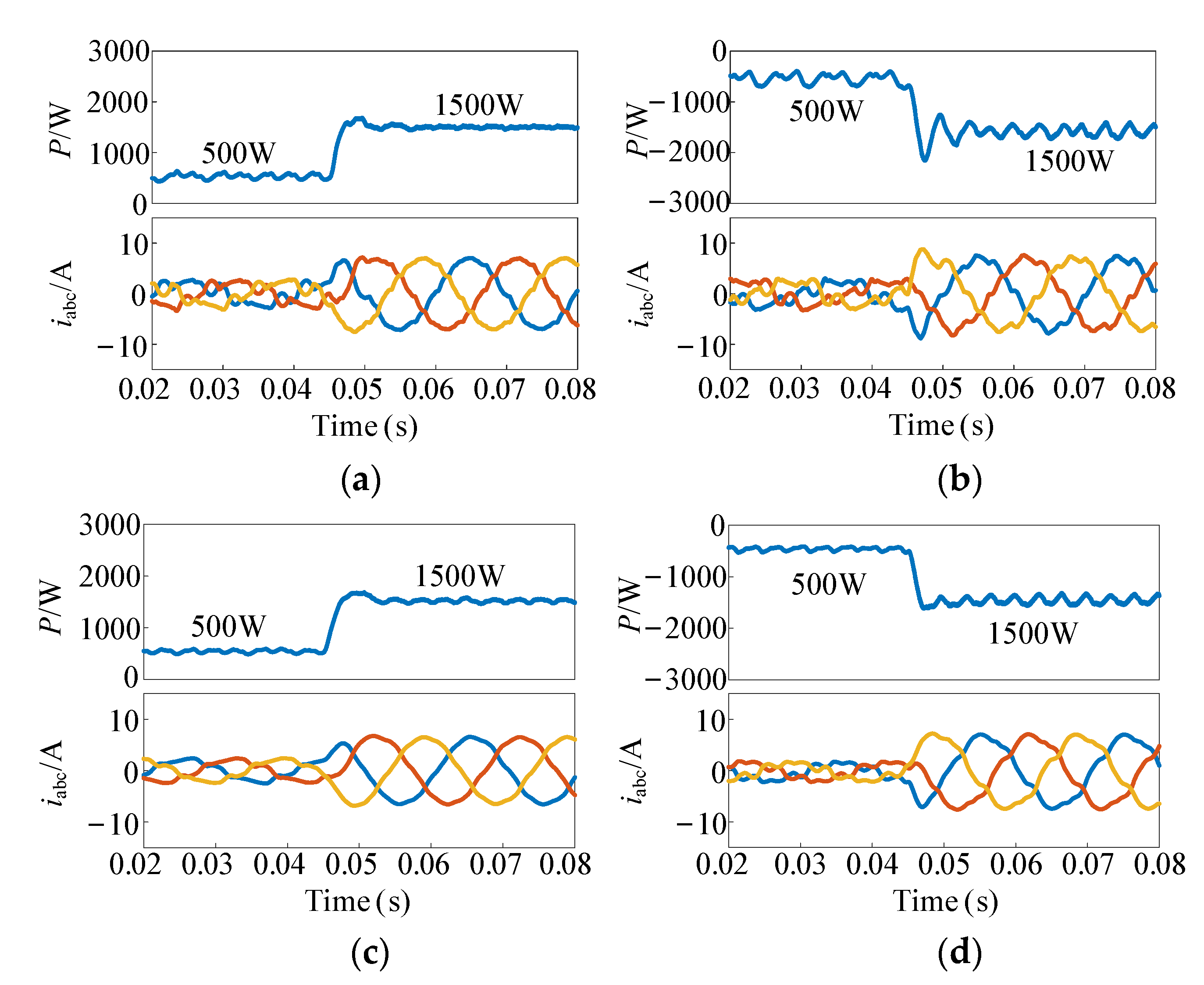
Figure 14 shows the simulation results at the low-power level with P changing from 500 W to 1500 W, and Ud = 155 V. As shown in Figure 14a,b, under conventional direct power control, the fluctuations of the power output and current in the forward power direction are slightly larger than that in the reverse direction when P changes. That demonstrates the existence of a stability difference between the two power directions. After adopting the IRSE control, the reverse negative impedance of the converter is reshaped to positive impedance. As shown in Figure 14c,d, the reverse fluctuations are reduced and the system stability is enhanced, making the bidirectional stability difference decreased.
To more clearly and intuitively demonstrate the bidirectional stability difference at the low-power level, through reducing Ud (Ud = 100 V), the simulation results as P changes are obtained and shown in Figure 15. The system stability in the reverse power direction is deteriorated, as reflected by the larger oscillations noted in Figure 15b. IRSE control, on the other hand, produces smaller oscillations in both the forward and reverse power directions. Therefore, IRSE control can offer a more uniform behavior that is less sensitive to voltage variations.
Figure 16 shows the simulation results of the traditional power control, the virtual impedance optimization control and the proposed optimization control when the forward and reverse powers have a step change. When the power flows in bidirectional directions, the virtual impedance can effectively suppress the power oscillation under the traditional power control, but there is the problem of the time delay of the current control loop and the low stability margin. IRSE control has a fast response time in both the forward and reverse power directions and is more sensitive to load changes.
Figure 17 next shows the simulation results at the high-power level with P changing and Ud = 155 V. Figure 17a,b shows the simulation results under conventional control. As illustrated, while P increases gradually, the system can still remain stable under the forward power flow. However, when the power flows along the reverse direction, the overshoot and oscillations become larger, while P increases from 10 to 20 kW, and the system can return to stability. While P continues to increase from 20 to 30 kW, the power output cannot return to stability and produces continuous large-scale oscillations. From Figure 17c,d, after using IRSE control, the overshoot and oscillations in the reverse power direction are reduced greatly, and the system can remain stable in both forward and reverse power direction. That means that the bidirectional stability difference is very obvious at the high-power level when P increases before optimization. The proposed method can effectively decrease the difference and enhance the system stability.

4.2. Experimental Results

In order to verify the simulation results at the low-power level, a scaled-down prototype was also built for experimental testing, and the image of prototype is shown in Figure 18. The experimental parameters are also shown in Table 1. The control unit is dSPACE MicroLabBox 1202/1302, and the power curves are observed on the oscilloscope. The results acquired are described as follows.
Figure 19 shows the experimental results with P increasing from 500 W to 1300 W and Ud = 100 V. Figure 19a,b illustrates the waveforms under conventional control. As shown, the system automatically returns to the novel steady state only with 2.7 ms in the forward power direction. However, under the reverse power flow, both the power and current waveforms produce a larger overshoot, and it took 8.6 ms to return to stability. After introducing the IRSE control, as shown in Figure 19c,d, the reverse overshoot is greatly reduced, and system can quickly return to stability in about 2.8 ms under bidirectional power flow.
Figure 20 then shows waveforms of power and grid-connected current with P increasing from 500 W to 1300 W and Ud = 80 V. Compared with Figure 19b, the overshoot and oscillations are larger in Figure 20b. The stability difference between the forward and reverse power becomes more obvious through reducing voltage. Compared with Figure 20b, the overshoot is decreased greatly, and the system stability is enhanced in Figure 20d due to the reshaping of the negative impedance to positive impedance. At same time, compared with Figure 20a, the forward stability is not influenced after using IESR control shown in Figure 20c.

5. Conclusions

This paper analyzed the impedance interactions for the bidirectional grid-connected converter. Impedance stability evaluations showed that, under conventional direct power control, the system stability will deteriorate in the reverse power direction, because of the negative impedance of the converter as a constant power load. Additionally, there is obvious bidirectional stability difference problem at the high-power level. At the low-power level, the stability difference existed in the margin domain, which is further widened through decreasing voltage. Based on these stability issues, the impedance-reshaped stability-enhancing control was proposed, which is capable of reshaping the converter input impedance from a negative-resistive to positive-resistive impedance in the low-frequency domain of reverse power mode. Moreover, the system can remain stable in both the forward and reverse power direction, and the bidirectional power transmission capacity can be increased. The conclusions are verified by the impedance bode plots, as well as with the Nyquist stability criterion. Simulations and experimental results are also provided to verify the effectiveness of the proposed control strategy.

Author Contributions

Methodology, Y.T.; Project administration, L.L.; Resources, Y.W.; Software, F.P.; Writing—original draft, K.W. Writing—review and editing, K.W. All authors have read and agreed to the published version of the manuscript.

Funding

This work was supported by the Zhejiang Electric Power Ltd. Technology Project, “Mod-elling of Multi-Voltage Level Flexible DC Transmission System and Interaction Mechanism with Connected AC Grid”, Proiect NO. (B311ZS220001).

Institutional Review Board Statement

Not applicable.

Informed Consent Statement

Not applicable.

Conflicts of Interest

The authors declare no conflict of interest.

References

  1. Loh, P.C.; Li, D.; Chai, Y.K.; Blaabjerg, F. Hybrid AC-DC microgrids with energy storages and progressive energy flow tuning. IEEE Trans. Power Electron. 2013, 28, 1533–1542. [Google Scholar] [CrossRef]
  2. Blaabjerg, F.; Teodorescu, R.; Liserre, M.; Timbus, A.V. Overview of control and grid synchronization for distributed power generation systems. IEEE Trans. Ind. Electron. 2006, 53, 1398–1409. [Google Scholar] [CrossRef] [Green Version]
  3. Tang, C.; Chen, Y.; Chen, Y.; Chang, Y. DC-link voltage control strategy for three-phase back-to-back active power conditioners. IEEE Trans. Power Electron. 2015, 62, 6306–6316. [Google Scholar] [CrossRef]
  4. Yang, L.; Chen, Y.; Luo, A.; Chen, Z.; Zhou, L.; Zhou, X.; Wu, W.; Tan, W.; Guerrero, J.M. Effect of phase-locked loop on small-signal perturbation modelling and stability analysis for three-phase LCL-type inverter connected to weak grid. IET Renew. Power Gener. 2020, 13, 86–93. [Google Scholar] [CrossRef]
  5. Tian, Y.; Chen, Z.; Deng, F.; Sun, X.; Hu, Y. Active power and DC voltage coordinative control for cascaded DC-AC converter with bidirectional application. IEEE Trans. Power Electron. 2015, 30, 5911–5925. [Google Scholar] [CrossRef] [Green Version]
  6. Sun, J. Small-signal methods for AC distributed power system—A review. IEEE Trans. Power Electron. 2009, 24, 2545–2554. [Google Scholar]
  7. Tian, Y.; Loh, P.C.; Chen, Z.; Deng, F.; Hu, Y. Impedance interactions in bidirectional cascaded converter. IET Power Electron. 2016, 9, 2842–2891. [Google Scholar] [CrossRef]
  8. Liu, H.; Xie, X.; He, J.; Xu, T.; Yu, Z.; Wang, C.; Zhang, C. Subsynchronous interaction between direct-drive PMSG based wind farms and weak AC networks. IEEE Trans. Power Syst. 2017, 32, 4708–4720. [Google Scholar] [CrossRef]
  9. Zhang, X.; Xia, D.; Fu, Z.; Wang, G.; Xu, D. An improved Feedforward control method considering PLL dynamics to improved weak grid stability of grid-connected inverters. IEEE Trans. Ind. Appl. 2018, 54, 5143–5151. [Google Scholar] [CrossRef]
  10. Shuai, Z.; Li, Y.; Wu, W.; Tu, C.; Luo, A.; Shen, Z. Divided dq small-signal model: A new perspective for the stability analysis of three-phase grid-tied inverters. IEEE Trans. Ind. Electron. 2020, 66, 6493–6504. [Google Scholar] [CrossRef]
  11. Wen, B.; Boroyevich, D.; Burgos, R.; Mattavelli, P.; Shen, Z. Analysis of D-Q small-signal impedance of grid-tied inverters. IEEE Trans. Power Electron. 2016, 31, 675–687. [Google Scholar] [CrossRef]
  12. Khaligh, E.A.; Rivetta, C.H.; Williamson, G.A. Constant power loads and negative impedance instability in automotive systems: Definition, modeling, stability, and control of power electronic converters and motor drives. IEEE Trans. Veh Technol. 2006, 55, 1112–1125. [Google Scholar]
  13. Tian, Y.; Loh, P.C.; Deng, F.; Chen, Z.; Sun, X.; Hu, Y. Impedance coordinative control for cascaded converter in bidirectional application. IEEE Trans. Ind. Appl. 2016, 52, 4084–4095. [Google Scholar] [CrossRef]
  14. Wu, W.; Chen, Y.; Zhou, L.; Zhou, X.; Yang, L.; Dong, Y.; Xie, Z.; Luo, A. A virtual phase-lead impedance stability control strategy for the maritime VSC–HVDC system. IEEE Trans. Ind. Informat. 2018, 14, 5475–5486. [Google Scholar] [CrossRef]
  15. Tian, Y.; Liu, T.; Wang, Y.; Yang, D.; Hao, Y.; Chen, Z. Virtual Impedance Refined Inductor Current Observation and Current Sensorless Control for Grid-Connected Inverter. IEEE Trans. Power Electron. 2022, 37, 10239–10249. [Google Scholar] [CrossRef]
  16. Huai, Q. A Virtual Impedance Control Strategy for Improving the Stability and Dynamic Performance of VSC–HVDC Operation in Bidirectional Power Flow Mode. Appl. Sci. 2020, 9, 3184. [Google Scholar]
  17. Huang, X.; He, Z.; Chen, Z.; Liu, Y.; Wu, W.; Xu, Q.; Zhou, L.; Luo, A. Stability assessment and coordinated impedance shaping strategy for DC bidirectional cascaded system with LC input filter. Int. J. Electr. Power Energy Syst. 2020, 115, 105429. [Google Scholar] [CrossRef]
  18. Harnefors, L.; Bongiorno, M.; Lundberg, S. Imput-admittance calculation and shaping for controlled voltage-source converters. IEEE Trans. Ind. Electron. 2007, 54, 3323–3334. [Google Scholar] [CrossRef]
  19. Fang, J.; Li, X.; Li, H.; Tang, Y. Stability Improvement for Three-Phase Grid-Connected Converters through Impedance Reshaping in Quadrature-Axis. IEEE Trans. Power Electron. 2018, 33, 8365–8375. [Google Scholar] [CrossRef]
  20. Li, Y.; Shuai, Z.; Liu, X.; Hong, Y.; Wu, X.; Shen, Z.J. Stability Investigation of Bidirectional AC-DC Converter Considering Operating Conditions. IEEE Access 2020, 8, 131499–131510. [Google Scholar] [CrossRef]
  21. Wen, B.; Boroyevich, D.; Burgos, R.; Mattavelli, P.; Shen, Z. Small-signal stability analysis of three-phase AC systems in the presence of constant power loads based on measured d-q frame impedances. IEEE Trans. Power Electron. 2015, 30, 5952–5963. [Google Scholar] [CrossRef]
  22. Cespedes, M.; Xing, L.; Sun, J. Constant-power load system stabilization by passive damping. IEEE Trans. Power Electron. 2011, 26, 1832–1836. [Google Scholar] [CrossRef]
  23. Burgos, R.; Boroyevich, D.; Wang, F.; Karimi, K.; Francis, G. On the ac stability of high power factor three-phase rectifiers. In Proceedings of the 2010 IEEE Energy Conversion Congress and Exposition, Atlanta, GA, USA, 12–16 September 2010; pp. 2047–2054. [Google Scholar]
  24. Wen, B.; Burgos, R.; Boroyevich, D.; Mattavelli, P.; Shen, Z. AC stability analysis and dq impedance specification in power electronics based distributed power systems. IEEE J. Emerg. Select. Top. Power Electron. 2017, 5, 1455–1465. [Google Scholar] [CrossRef]
  25. Du, Y.; Cui, L.; Yang, X.; Su, J.; Wang, F. Impedance-phase reshaping of LCL-filtered grid-connected inverter to improve the stability in a weak grid. In Proceedings of the 2017 IEEE Energy Conversion Congress and Exposition (ECCE), Cincinnati, OH, USA, 1–5 November 2017; pp. 2921–2926. [Google Scholar]
  26. Wen, B.; Dong, D.; Boroyevich, D.; Burgos, R.; Mattavelli, P.; Shen, Z. Impedance-based analysis of grid-synchronization stability for three-phase paralleled converters. IEEE Trans. Power Electron. 2016, 31, 26–38. [Google Scholar] [CrossRef]
  27. Leppaaho, J.; Huusari, J.; Nousiainen, L.; Puukko, J.; Suntio, T. Dynamic properties and stability assessment of current-fed converters in photovoltaic applications. IEEE Trans Ind. Appl. 2011, 131, 976–984. [Google Scholar] [CrossRef]
  28. Wildrick, M.; Lee, F.C.; Cho, B.H.; Choi, B. A method of defining the load impedance specification for a stable distributed power system. IEEE Trans. Power Electron. 1995, 10, 280–285. [Google Scholar] [CrossRef]
  29. Yang, D.; Ruan, X.; Wu, H. Impedance Shaping of the Grid-Connected Inverter with LCL Filter to Improve Its Adaptability to the Weak Grid Condition. IEEE Trans. Power Electron. 2014, 29, 5795–5805. [Google Scholar] [CrossRef]
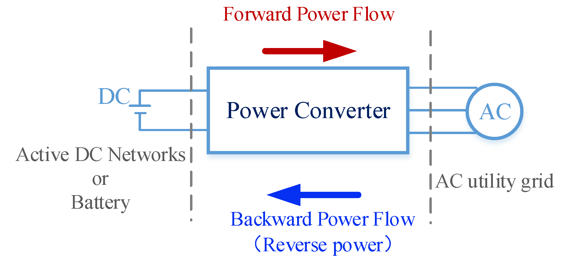
Figure 1. Bidirectional DC/AC converter.
Energies 15 07269 g001
Figure 2. Grid-connected converter system. (a) Topology; (b) control unit under conventional direct power control.
Energies 15 07269 g002
Figure 3. Small-signal model of grid-connected converter with conventional direct power control under forward power flow.
Energies 15 07269 g003
Figure 4. Small-signal model of grid-connected converter with conventional direct power control under reverse power flow.
Energies 15 07269 g004
Figure 5. Bode plots of converter output and input impedance as power increases. (a) Output impedance under forward power flow; (b) input impedance under reverse power flow.
Energies 15 07269 g005aEnergies 15 07269 g005b
Figure 6. Thevenin Norton equivalent circuit of bidirectional grid-connected converter system under conventional direct power control.
Energies 15 07269 g006
Figure 7. Nyquist plots obtained as power increases under conventional direct power control: (a) in the forward power direction and (b) in the reverse power direction.
Energies 15 07269 g007
Figure 8. Control scheme of impedance-reshaped stability-enhancing control.
Energies 15 07269 g008
Figure 9. Equivalent circuit under IRSE control in reverse power direction.
Energies 15 07269 g009
Figure 10. Converter small-signal block diagram under IRSE control: (a) in the forward power direction and (b) in the reverse power direction.
Energies 15 07269 g010
Figure 11. Bode diagram under conventional control and IRSE control at 15 kW.
Energies 15 07269 g011
Figure 12. Nyquist plots obtained with power increased with IRSE control: (a) in forward power direction; (b) in reverse power direction.
Energies 15 07269 g012
Figure 13. Nyquist plots obtained with voltage reduced for reverse power flow at 1.5 kW: (a) conventional control and (b) IRSE control.
Energies 15 07269 g013
Figure 14. Simulation results at the low-power level as P changes, with Ud = 155 V. (a) Conventional control under forward power flow. (b) Conventional control under reverse power flow. (c) IRSE control under forward power flow. (d) IRSE control under reverse power flow.
Energies 15 07269 g014
Figure 15. Simulation results at low-power level as P changes, with Ud = 100 V. (a) Conventional control under forward power flow. (b) Conventional control under reverse power flow. (c) IRSE control under forward power flow. (d) IRSE control under reverse power flow.
Energies 15 07269 g015
Figure 16. Simulation results with different control strategies at the low-power level as P changes, with Ud = 155 V: (a) under forward power flow and (b) under reverse power flow.
Energies 15 07269 g016aEnergies 15 07269 g016b
Figure 17. Simulation results at the high-power level as P changes, with Ud = 155 V. (a) Conventional control under forward power flow. (b) Conventional control under reverse power flow. (c) IRSE control under forward power flow. (d) IRSE control under reverse power flow.
Energies 15 07269 g017
Figure 18. Experimental setup.
Energies 15 07269 g018
Figure 19. Experimental results as P changes, with Ud = 100 V. (a) Conventional control under forward power flow. (b) Conventional control under reverse power flow. (c) IRSE control under forward power flow. (d) IRSE control under reverse power flow.
Energies 15 07269 g019
Figure 20. Experimental results as P changes, with Ud = 80 V. (a) Conventional control under forward power flow. (b) Conventional control under reverse power flow. (c) IRSE control under forward power flow. (d) IRSE control under reverse power flow.
Energies 15 07269 g020
Table 1. System parameters.
ParameterValue
Udc400 V
ωg2π × 50 rad/s
fsw10 kHz
C400 uF
Lf3 mH
Rf0.1 Ω
Lg1 mH
Rg0.1 Ω
Publisher’s Note: MDPI stays neutral with regard to jurisdictional claims in published maps and institutional affiliations.