Article

Thermo-Economic Assessments on a Heat Storage Tank Filled with Graded Metal Foam

1
Institute of the Building Environment & Sustainability Technology, School of Human Settlements and Civil Engineering, Xi’an Jiaotong University, Xi’an 710049, China
2
China Northwest Architecture Design and Research Institute, Co., Ltd., Xi’an 710077, China
3
State Key Laboratory for Strength and Vibration of Mechanical Structures, School of Aerospace, Xi’an Jiaotong University, Xi’an 710049, China
*
Authors to whom correspondence should be addressed.
Energies 2022, 15(19), 7213; https://doi.org/10.3390/en15197213
Submission received: 2 September 2022 / Revised: 14 September 2022 / Accepted: 26 September 2022 / Published: 30 September 2022
(This article belongs to the Topic Thermal Energy Transfer and Storage)

Abstract

:
To save and better deploy waste heat, the use of a mobilized heat storage system (MHSS) with phase change enhancement means is developed. In this paper, three kinds of gradient structures (positive gradient, negative gradient, and non-gradient) are designed in the MHSS system. The uniform porosity is 94% in the non-gradient structure, and the gradient porosities are 86%, 93%, and 98% in the gradient structure, respectively. Numerical models are developed to explore the contribution of the graded metal foam structure to the heat storage and release process. An economic analysis and comparison of MHSS systems with different heat transfer models are carried out. The results show that the positive gradient case can promote the thermal cycle of the melting and solidification process, while the negative gradient case inhibits the thermal cycle. The positive gradient case can reduce the melting time by 9.7% and the solidification time by 4.4%, while the negative gradient can prolong the melting time by 31.4% and the solidification time by 35.9%. Although graded metal foam increases the initial investment by 76.09%, the 1 KW·h heat cost of graded metal foam is reduced by 10.63% compared to pure phase change material (PCM). It is cost-effective in the long run of thermal cycles.

1. Introduction

Nowadays, the world’s energy demand is increasing with the current increase in the population and the development of industrialization. While it is difficult to reduce the world’s total amount of energy required, it is important to focus on saving and better deploying existing energy sources. Nearly 1/3 of the industrial energy consumption is discharged as waste heat, usually in the low temperature range [1]. Thermal energy storage systems (TES) with phase change materials (PCMs) can offer waste to heat [2,3], renewable energy storage [4,5], air conditioning cooling [6,7], and envelope improvements [8,9]. In practice, latent heat storage employs PCMs that can absorb and release a large amount of thermal energy with a small temperature fluctuation; it is superior to sensible heat storage and chemical reaction heat storage [10,11]. In addition, since the energy demand of each region is usually not uniform, it is necessary to allocate energy according to the different needs in this region. District heating has been widely used in places with a high density for heating demand [12]. However, district heating is not suitable for scattered remote areas and independent houses due to relatively small heat demand. Given the above analysis of much industrial waste heat, a mobilized heat storage system (MHSS) is utilized to transport and recover waste heat from factories to distributed houses, as demonstrated in Figure 1.
MHSS not only has the role of a TES system in saving renewable energy and waste heat utilization, but can also flexibly adjust the energy of each region to solve the mismatch problem of energy supply and demand [13,14,15,16]. Existing investigations have extensively studied the performance of various aspects of the MHSS system and proved the feasibility of the system. Du et al. [17] investigated the difference between the direct and indirect heat storage in a MHSS for storing low-temperature thermal energy. It was found that direct heat storage can reduce the heat release time by 60% compared with the indirect heat storage. Guo et al. [18] found that red alginol and sodium acetate trihydrate were appropriate for the MHSS with low temperatures in the configuration of shell and tube containers. Wang et al. [19] experimentally tested an indirect-contact heat exchanger using sodium acetate trihydrate and estimated the final thermal efficiency at 79.4%. Guo et al. [20] conducted a technical and economic feasibility analysis on the MHSS. They suggested that the best performance was achieved when two containers were used and the transportation cycle was 4.
Nevertheless, the engineering PCMs used in MHSS usually have low thermal conductivity, thereby limiting the wide spread of MHSS across energy storage and release through transportation. Previous studies have proved that PCM with high thermal conductivity material can strengthen the heat transfer and conduction of the PCM. To enhance the thermal conductivity of the PCM, a variety of methods have been developed, including adding fins [21,22,23,24], heat pipes [25,26,27], nanomaterials [28,29,30], microcapsules [31,32,33], and combinations of the above. Compared to the pure PCM, Rahmanian et al. [34] proposed that the foam–PCM sink can mitigate the complete melting time by 13.6%. Mahdi et al. [35] simulated the melting and solidification process of PCM with metal foam. Their results indicated that metal foam can accelerate the melting/solidification of PCM and improve temperature uniformity. Moreover, a new encapsulated PCM–metal foam hybrid system is proposed by Baruah et al. [36]. Among them, porous metal foam [37], which has a high surface area and high thermal conductivity due to their metallic skeleton structure, is generally regarded as a superior means of heat transfer argumentation. The strengthening effect of the metal foam itself and in combination with various other strengthening methods have been proved by many studies [34,38,39,40]. A decrease in the porosity of metal foam usually results in a decrease in melting time at the expense of reducing heat storage [41,42,43]. However, the change of pore density of metal foams has no significant effect on the melting process [44,45].
To further improve the thermal performance under the given mass of metal foam, a graded pore structure has been developed [46,47,48]. Studies have proved that the metal foam layout strategy with a gradient structure is feasible [45,49]. Zhang et al. [49] investigated the PCM phase transition process in a vertical container with aluminum foam. It was revealed that the linear gradient structure could enhance the heat transfer in the bottom region and improve the overall efficiency compared with the uniform structure. Zhang et al. [50] compared the effect of metal foams with different filling heights on the melting process by experimental means. Based on the filling height of 5/6, it was found that in the graded porosity structure, the part with a larger porosity near the heating surface helped to accelerate melting.
Through the investigation of the literature, it can be concluded that the existing studies have been determining the thermal performance under uniform parameters for metal foams. The attempts at gradient structure design are still in an immature stage. The thermal and economic characteristics of gradient metal foam structures in the MHSS are not fully understood. To address this important issue, this paper aims to further clarify the heat storage and release characteristics of the horizontal graded metal foam structure in PCM, and also to analyze the economy of the composite structure in the MHSS system. A horizontal TES tank with graded metal foam is designed, and the influence of the structure on the heat storage and release characteristics of PCM is analyzed by means of numerical simulation. On this basis, the economic analysis of MHSS system using this composite structure is carried out.

2. Numerical Simulation

2.1. Model Description

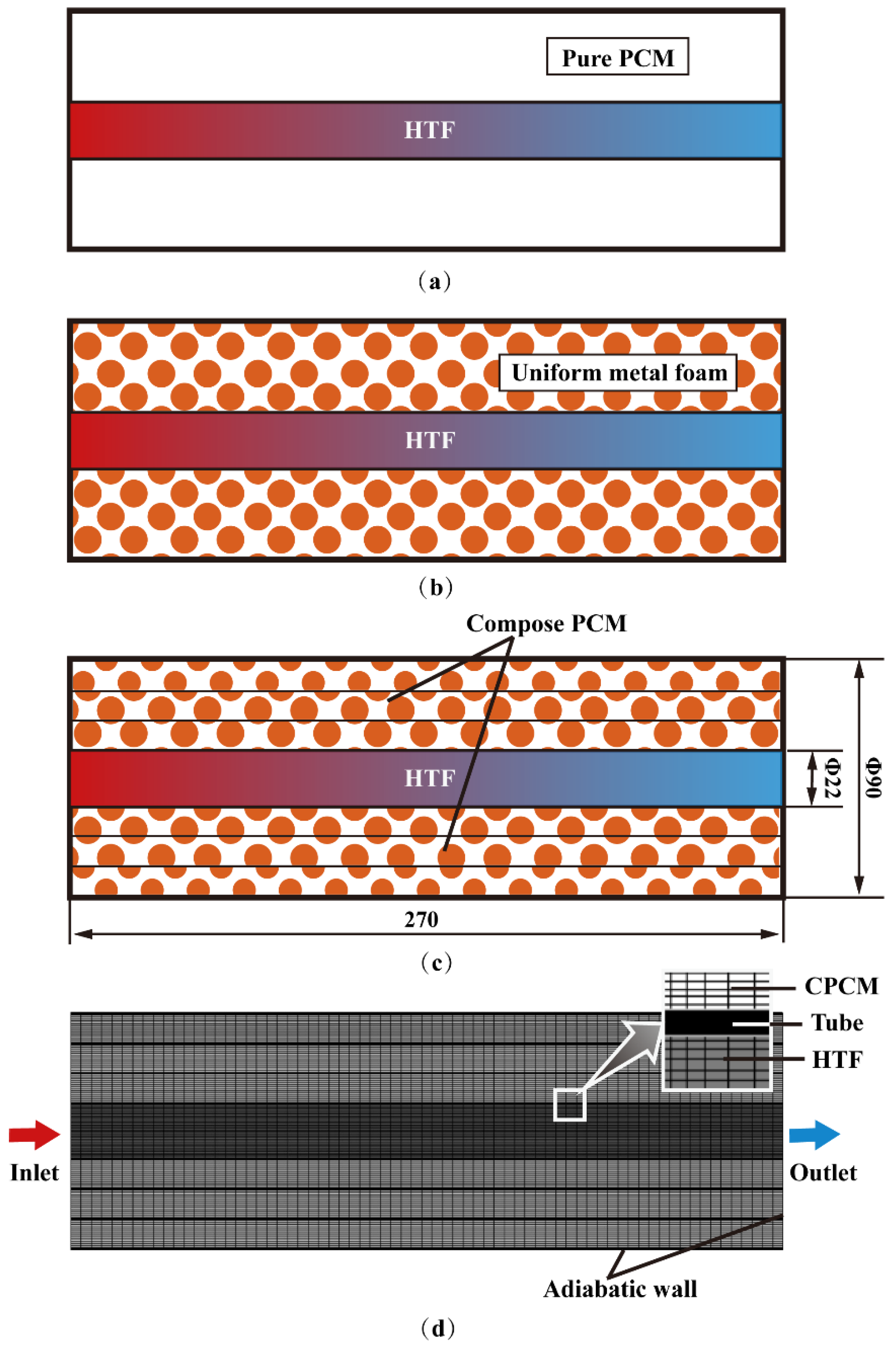
In the current study, three structures (pure PCM, uniform metal foam, and gradient metal foam) are designed in Figure 2a–c. The horizontal pipe cannot be reduced to a two-dimensional model because gravity will affect the natural convection. However, due to the symmetry of the structure, we take half of the structure as the object of the simulation, as shown in Figure 2d. The length of the entire TES tube is 270 mm, the diameter of the outer and the inner tube are 90 mm and 22 mm, respectively, and the wall thickness of the inner tube is 1 mm. The inner metal foam is divided into three layers with the same thickness, which are filled with metal foam of different porosities, respectively.

2.2. Governing Equations

Continuity equation:
ρ l t + ( ρ l U ) = 0
Momentum equation:
x-direction:
ρ l σ u t + ρ l σ 2 ( U ) u = P x + μ l σ 2 u ( μ l K + ρ l C E K | U | ) u ( 1 f m ) 2 f m 3 + δ A m u + ρ f g γ ( T f T m 1 )
y-direction:
ρ l σ v t + ρ l σ 2 ( U ) v = P x + μ l σ 2 v ( μ l K + ρ l C E K | U | ) v ( 1 f m ) 2 f m 3 + δ A m v + ρ f g γ ( T f T m 1 )
z-direction:
ρ l σ w t + ρ l σ 2 ( U ) w = P z + μ l σ 2 w ( μ l K + ρ l C E K | U | ) w ( 1 f m ) 2 f m 3 + δ A m w + ρ f g γ ( T f T m 1 )
Energy equation for paraffin:
ε ρ f ( c p , f + L d f m d T f ) T f t + ρ f c p , f U T f = 2 ( λ f e + λ t d ) T f h s f a s f ( T f T s )
Energy equation for metal foam:
( 1 ε ) ρ s c p s T s t = ( λ s e T s ) h s f a s f ( T s T f )
For the above equations, the symbol is the implement on the volume average; σ is the liquid fraction in metal foam, ( σ = ε f f ); ρ l , μ l , γ, cp,f, λ t d , λ f e , and L denote density, dynamic viscosity, thermal expansion coefficient, specific heat, thermal dispersion coefficient, thermal conductivity and latent heat fusion, respectively; and for PCM, h s f , ρ s , c p s , λ s e , K, c E , ε , and a s f density, specific heat, effective thermal conductivity, permeability, porosity, specific surface area for metal foam, respectively f m is determined by
f m = { 0 T < T m 1 T T m 1 T m 2 T m 1 T m 1 T T m 2 1 T > T m 2
where δ = 10 4 and A m = 10 5 . When f m = 0, Am approaches infinity, and the value of δ ensures that the denominator is not zero.
The heat transfer coefficient h s f is estimated by [51]:
h s l = { 0.76 Re 0.4 Pr 0.37 λ f / D , 0 < Re 40 0.52 Re 0.5 Pr 0.37 λ f / D , 40 < Re 1000 0.26 Re 0.6 Pr 0.37 λ f / D , 1000 < Re 20000
Effective   thermal   conductivity   λ e is [52]:
λ e = ( 1 ε ) λ s ( 1 e + 3 e 2 α ) [ 3 ( 1 e ) + 3 2 α e ] + λ f ε
The model not only accurately characterizes the pore morphology of the open-cell metal foam, but also reasonably estimates the size of the nodes. In addition, the model can accurately predict the effective thermal conductivity of the metal foam. When the fluid conductivity kf is equal to 0, the solid effective conductivity kse can be obtained; likewise, the fluid effective conductivity kfe is obtained by setting ks = 0 in Equation (9).
Thermal dispersion conductivity λ t d is [53]:
λ t d = 0.36 1 ε ρ f c p f D u 2 + v 2 + w 2
Permeability K and inertial coefficient CE are [53,54]:
K = ε [ 1 ( 1 ε ) 1 / 3 ] 108 [ ( 1 ε ) 1 / 3 ( 1 ε ) ] d p 2
C E = 0.095 c d 12 ε 3 ( χ 1 ) ( 1.18 1 ε 3 π 1 G ) 1
where c d is the resistance coefficient ( c d = 1.56 [55]), χ denotes the tortuosity, and G represents the shape factor [56]
χ = ε 1 ( 1 ε ) 1 / 3
G = 1 e ( 1 ε ) / 0.04

2.3. Independence and Simulation Verification

ANASYS ICEM is employed to generate the structured grid as show in Figure 2b. In particular, local encryption is performed between the HTF, the inner tube, and the metal foam. Based on the total phase transition time, three different numbers for grids and three different time steps are compared (as shown in Table 1). Compared with the grid number of 637,328, the total phase transition time is reduced by 10.4% while using the grid number of 194,732. The total phase transition time increased by 1.85% when the grid number is 1,621,629. This shows that when the grid number is 637,328, the computing resources can be reduced as much as possible while the calculation accuracy is guaranteed. Similarly, regardless of the time step of 0.05 s, 0.5 s, or 0.1 s, the total phase transition time remains the same. This indicates that the time step of 0.5 s can ensure the correctness of the results.
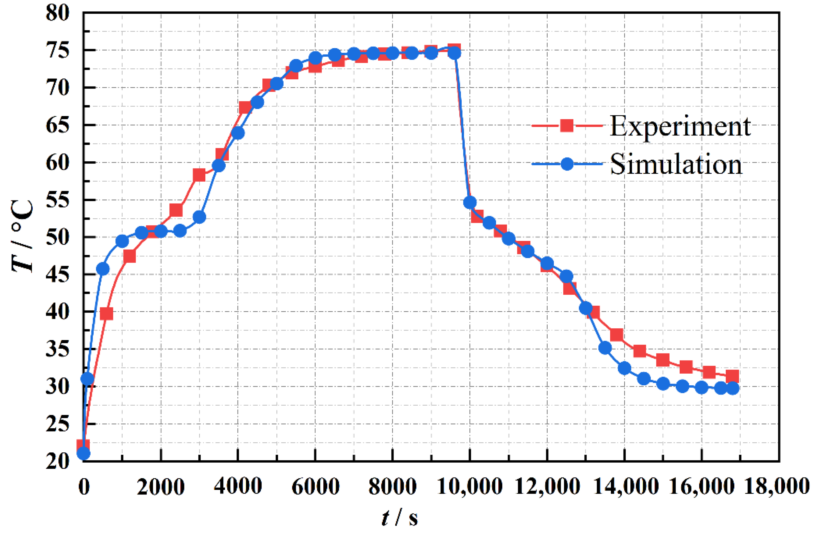
To verify the reliability of the numerical model, Figure 3 compares the current numerical simulation results with the measured data. The simulation results are consistent with the measuring results. The average relative deviation between the simulated and measured values is less than 3.6%. There are some factors leading to the deviation between simulation and experiment. During the experiments, the external ambient temperature is difficult to always maintain at a constant. Furthermore, PCM is amorphous and its physical properties are not fixed. Moreover, the physical properties and condition settings cannot be kept the same as the experiments in the simulations. The superposition of these factors causes the simulation results in this paper to be slightly different from the experiment. Generally, the numerical model developed in the current study is correct, and it can be used for subsequent simulations.

2.4. Numerical Settings

The boundary conditions are set as shown in Figure 2b. The outer pipe wall is adiabatic condition, and the cross section is symmetric condition. The inlet velocity and temperature are 0.05 m∙s−1 and 70 °C, respectively. The initialization temperature is 22 °C. ANSYS-Fluent 2019 R3 is employed to solve the pressure base. Gravity (9.8 m∙s−2), the energy equation model, the laminar flow model, and the solidification/melting model are introduced. The thermal properties of the materials used in the simulations are shown in Table 2.

3. Results and Discussion

3.1. Evolution of Liquid Fraction

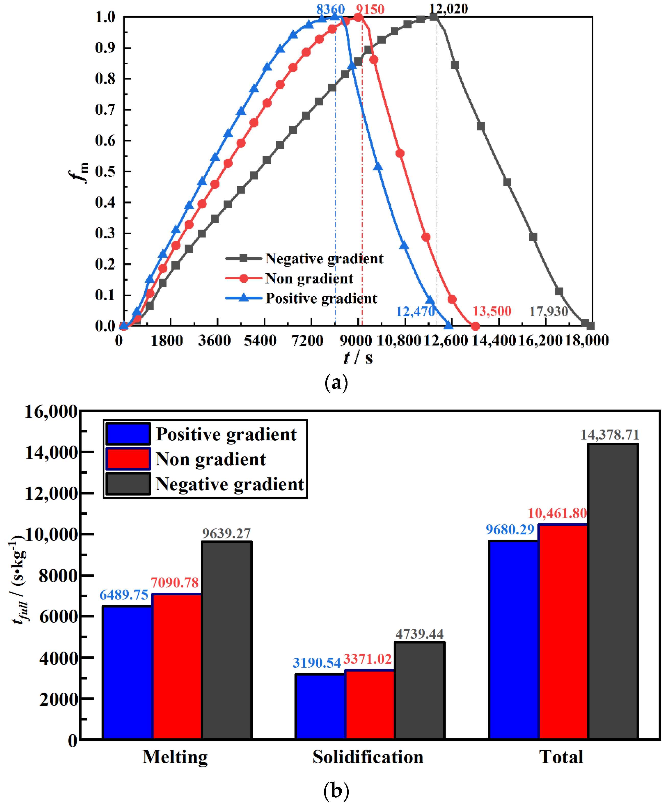
Figure 4 depicts the liquid rate curve with time for three kinds of structures. The positive gradient structure is defined as the porosity increasing from the inner wall to the outer tube of metal foams, i.e., porosity has a step increase from 86% to 93% to 98%. The total phase transition time is 12,470 s, 13,500 s, and 17,930 s in the case of a positive gradient, no gradient, and negative gradient (see Figure 4a), respectively. A total 7.6% reduction in complete time for the thermal cycle of energy charging/discharging is achieved.
The total phase transition time can be divided into two stages: melting stage and solidification stage. In the melting stage, the difference of liquid rate between the three gradients is gradually enlarged at 0–6000 s. This indicates that different gradient designs have an obvious influence on the melting process of the PCM. After 6000 s, the difference in the liquid phase rate for the three gradients gradually decreases. Finally, compared with the non-gradient case, the melting time of the positive gradient and the negative gradient decreased by 9.7% but increased by 31.4%, respectively. In the solidification stage and the initial internal liquid phase, natural convection dominates the heat transfer process. Therefore, the positive gradient case solidifies the fastest. In this case, compared with the non-gradient case, the solidification time of the positive gradient and the negative gradient decreased by 4.4% and increased by 35.9%, respectively. To eliminate the influence of mass change, the melting time per unit mass of PCM is demonstrated in Figure 4b. Compared with the non-gradient, the complete phase transition time per unit mass of the positive gradient is reduced by 7.5%. In addition, the complete phase transition time per unit mass of the positive gradient of the negative gradient increased by 37.4%.

3.2. Economic Analysis of Mobile Heat Storage System

3.2.1. Cost Analysis

For mobile heat storage systems, the cost and heating capacity are vital concerns. Economic analysis is crucial and necessary to understand the impact degree of critical parameters. Total cost [57] includes initial investment (I) and operation and maintenance costs (COSTom), thereby the total cost (COST) can be expressed as:
C O S T = m I ( 1 + i ) n + C O S T o m ( ( 1 + i ) n 1 i )
where the initial investment I consists of the cost of the composite phase change materials, water pump and pipeline installation, and transport vehicle. On the one hand, m is the number of systems, where the minimum quantity of continuous heat supply is 2. On the other hand, n indicates the life cycle, which is assumed to be 15 years. Finally, i represents the discount rate, calculated from the bank’s annual interest rate (u) and inflation rate (f):
i = u f 1 + f
Operating and maintenance costs comprise the heating energy costs, transportation costs (COSTT), and maintenance costs. Among them, since the waste heat available for heating in north China is 2.93 EJ [58], the heating energy consumption is assumed to be 0. Meanwhile, the maintenance cost is assumed to be 5% of the initial investment, mainly considering replacing phase change materials and the maintenance of system accessories. The following formula determines the operation and maintenance costs:
C O S T O M = 2 Q A t h e a t Q p c m D i s t C O S T T + 5 % I
where Q is the heating load per unit area. According to the energy-saving heating standard of Xi’an, it should be 42.2 W m 2 . Here, t h e a t is the heating period, which is 120 days in Xi’an. A is the area of the building heating area. In addition, Q p c m and Dist are the amount of heat that can be supplied by a transporter and the haul distance from the heat source to the heat user. To reserve the expansion volume, the maximum volume occupied by the PCM cannot exceed 85% of the storage container space. Considering the heat loss of the heat storage/release in the process of transportation, the heat storage and release efficiency are assumed to be 85% of the theoretical value in the current study. Total heat storage will affect the transportation cost because of the limited amount of heat in a single transport. To better measure the cost of heat, the cost of providing 1 KW h heat is taken as the standard. The waste heat cost in heat storage and heat release cannot be ignored. Finally, the cost calculation formula of 1 KW h heat provided by the mobile heat storage system is given:
C O S T = m I ( 1 + i ) n + C O S T o m ( ( 1 + i ) n 1 i ) Q A n t h e a t + C O S T w
The costs of the mobile phase change heat storage system (excluding the transporter) are summarized in Table 3. Three common transporters are selected as transport vehicles for the mobile heat storage system, as shown in Table 4. Since the transport vehicle has requirements on both load and volume, it is found that PCM should be loaded according to the standard load by calculating the density of PCM. At this point, the volume of the composite PCM does not exceed 85% of the internal volume.

3.2.2. Cost Calculation of Three Structures

For mobile heat storage systems, the economics of metal foam first need to be estimated. Trunk2 is employed to calculate the cost and heat storage of the three structures (pure PCM, uniform metal foam (MF), gradient design of metal foam). Moreover, Table 5 documents the heat storage and cost of the three structures. However, different user areas must match different haul distances in real life. Therefore, it is inevitable to calculate the maximum heating capacity in different haul distances.
Q max = m Q p c m n 24 t h e a t ( 2 D i s t / v ) + t max
where v is the transport speed of the transport vehicle, which is 50 km/h. In addition, t max is the maximum heat storage time and heat release time. According to the simulation results, the t max of pure PCM, uniform MF, and positive gradient MF is 12 h, 2.54 h, and 2.3 h, respectively. Therefore, the equation for calculating the operation and maintenance costs under the premise of maximum heat storage becomes as follows:
C O S T O M = 2 Q max Q p c m D i s t C O S T T + 5 % I
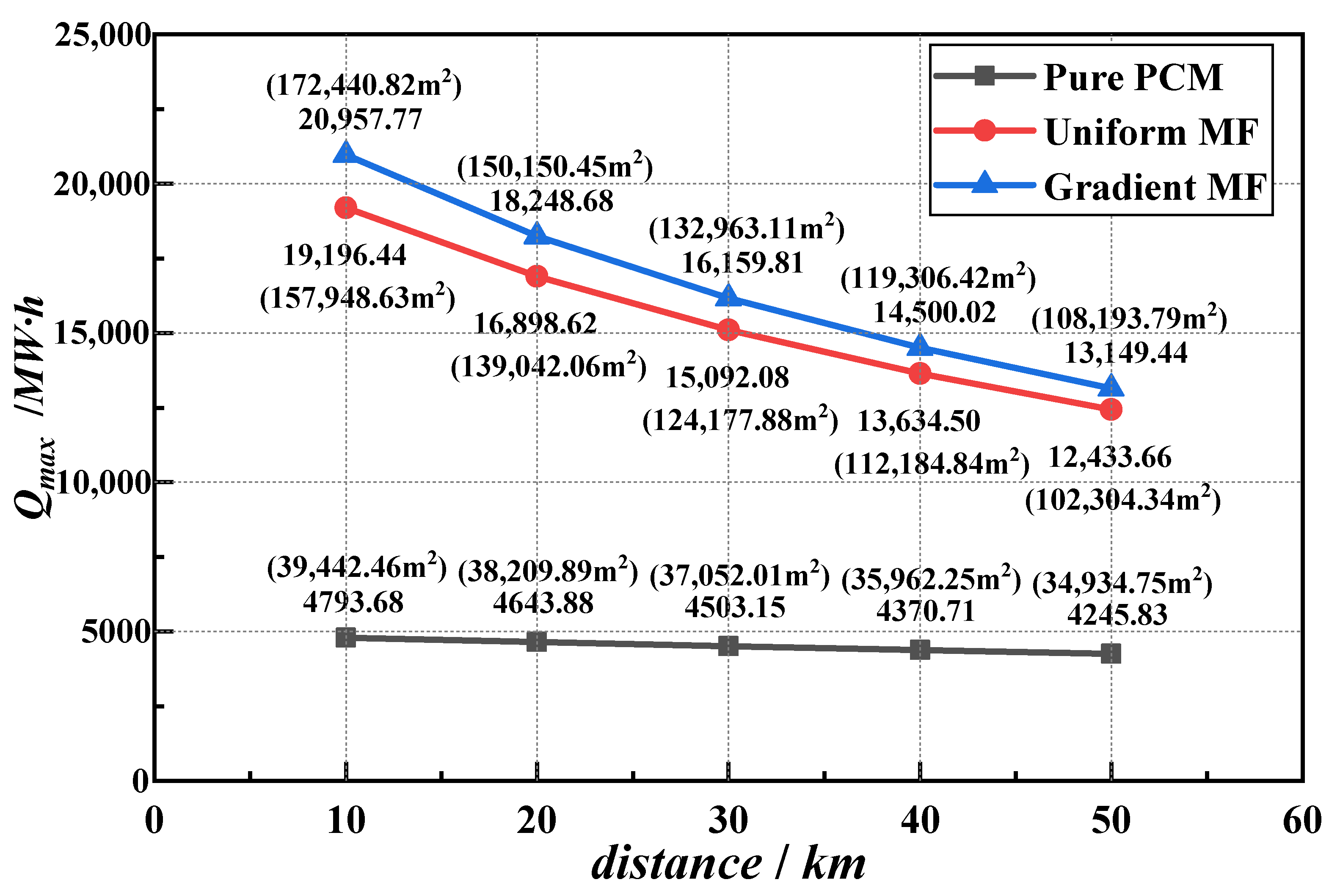
According to Equation (19), the maximum heating capacity versus distance is obtained in Figure 5. The value in brackets indicates the heating area corresponding to the heat. Since the built-up area of Xi’an city is about 729 km2, the traffic distance of 10–50 km can meet the transportation demand of different locations in the city. In Figure 5, the maximum heating capacity (Qmax) of three structures decreases with increasing distance. Compared with pure PCM, the Qmax of uniform MF and positive gradient MF separately increases by 235.14% and 258.86% at a distance of 30 km. The main reason for the difference in heat capacity is the dissimilarity in heat storage time. The pure PCM has the most heat storage time. Moreover, the variation in heat storage in a single vehicle is slight. Therefore, the Qmax of pure PCM is the minimum under the premise of 24-h operation.
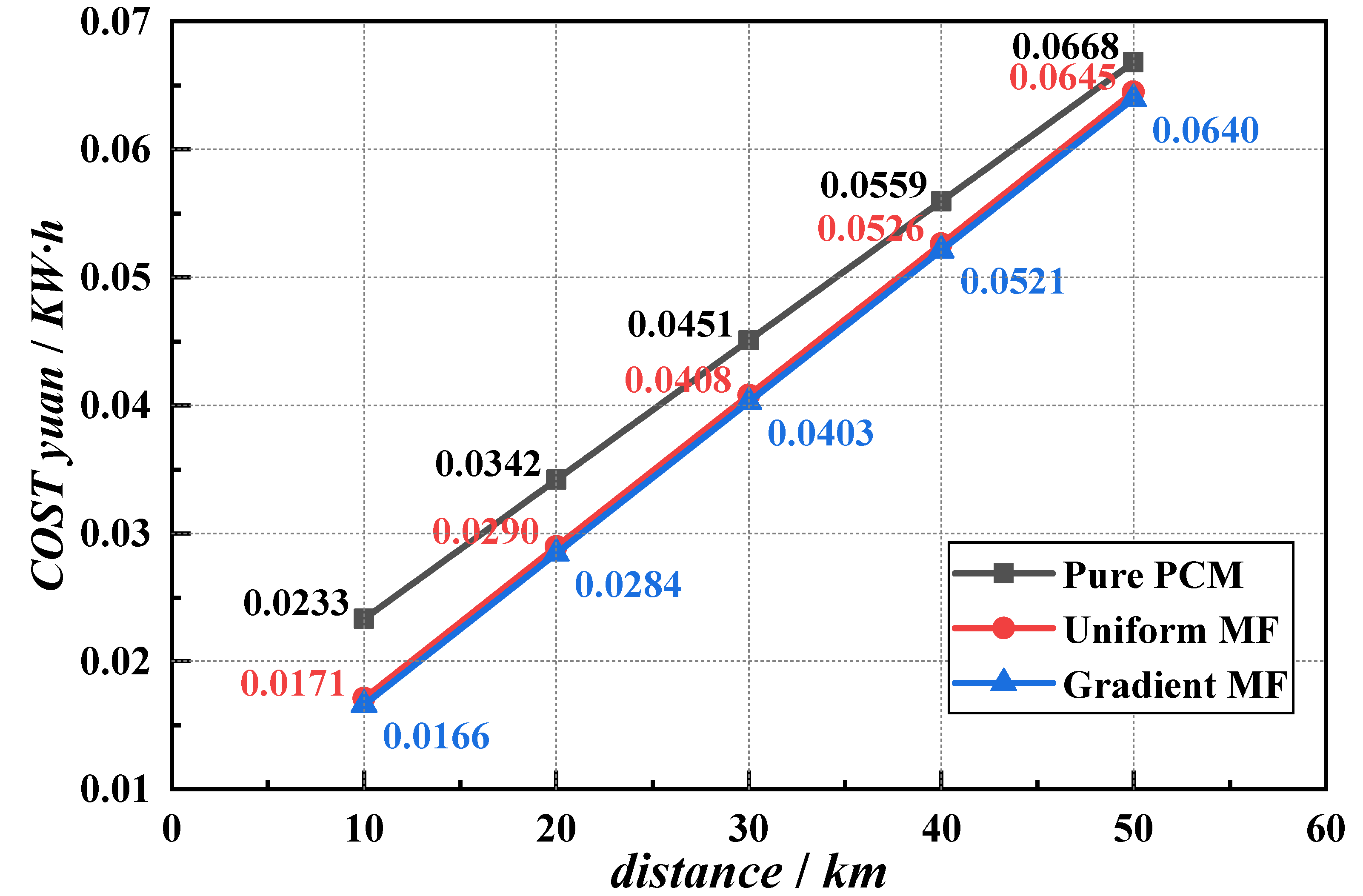
Using the maximum heating capacity in Figure 5 as the user demand, the cost of providing 1 KW h heat is calculated, as demonstrated in Figure 6. The cost of three structures varies almost linearly with distances. Within the distance of 10–50 km, the cost growth rates of pure PCM, uniform MF, and positive gradient MF are 0.00109 yuan / ( KW h km ) , 0.00118 yuan / ( KW h km ) , yuan / ( KW h km ) , respectively. Compared with pure PCM, positive gradient MF costs reduce by 28.79%, 16.84%, 10.63%, 6.84%, and 4.28% for the five distances (from 10 km to 50 km). However, transportation costs are also rising rapidly with the distance and frequency of transportation increase. It should be pointed out that the cost of positive gradient MF is still 1.26% less than that of uniform MF at a distance of 30 km.

3.2.3. Cost Calculation of Three Transport Vehicles

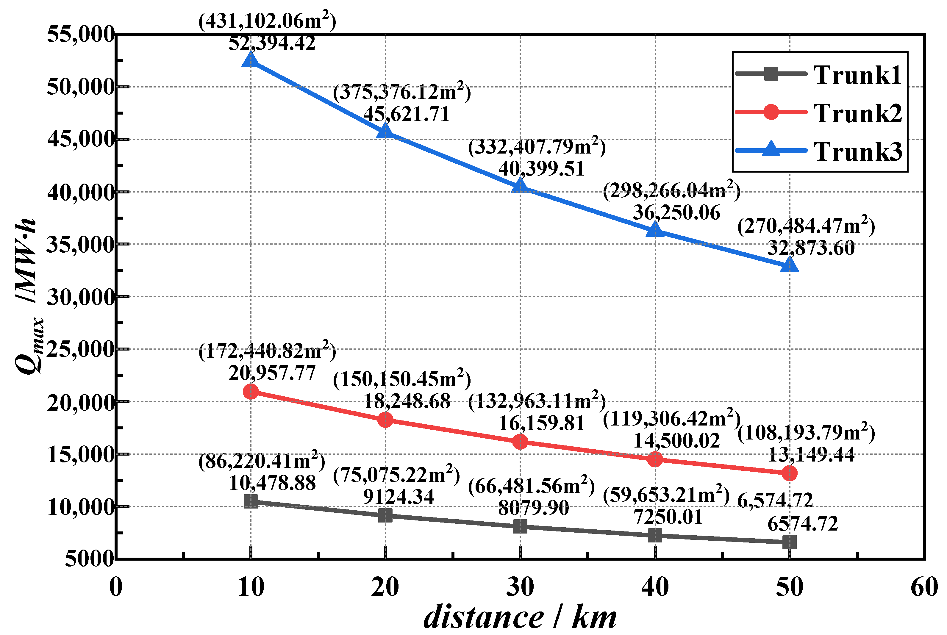
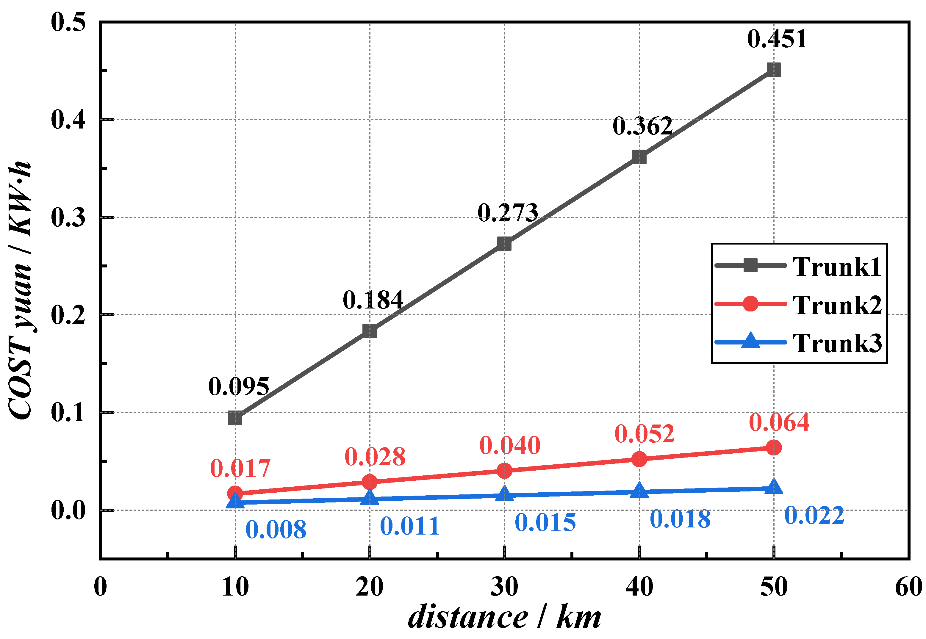
Based on the positive gradient MF structure, the cost and heat storage of different transport vehicles are presented in Table 6. Figure 7 indicates that the maximum heating capacity of the three transport vehicles decreases as the haul distance increases. According to Equation (19), the difference of Qmax is only affected by the haul distance and the heat provided by a transport vehicle. Therefore, they have similarly changed trends. Furthermore, the maximum heating capacity of Trunk3 is 2.5 times that of Trunk2 and 5 times that of Trunk1 at different haul distances. Meanwhile, the cost of different distances is calculated for the three vehicle types when the heating capacity is the maximum. The calculation results are compared in Figure 8. At this time, the final cost has dropped to below 0.451 yuan / ( KW h ) due to the substantial increase in user thermal demand. However, the cost growth rate of the three models is significantly different: Trunk1 is 0.0089 yuan / ( KW h km ) , Trunk2 is 0.0012 yuan / ( KW h km ) , and Trunk3 is 0.00036 yuan / ( KW h km ) , respectively.
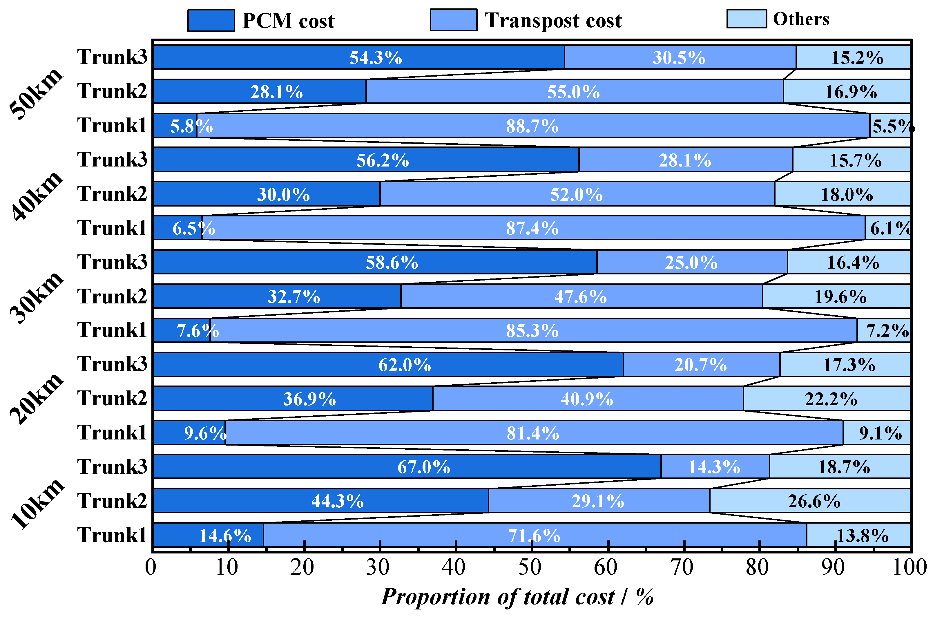
In addition, Figure 9 documents the proportion of the total cost. To intuitively observe and analyze the specific reasons for the difference in the costs of the three structures, the costs are divided into PCM cost, transport cost, and others (maintenance costs, trunk, and installation costs). It can be found that the most significant change is the transportation cost by comparing the cost of different vehicle types at different distances. The proportion of the transportation costs increases with the distance for the three models. Since PCM cost is a fixed value, the proportion of transport cost can directly reflect the transport cost. Trunk1 has the most transportation costs at different distances, resulting in the maximum total cost of Trunk1. When the initial investment is constant, the impact of 1 KW·h heat cost on transportation cost increases with the increase of total transportation times, total haul distance, and total heat supply. Thus, Trunk3 is the most economical but has the highest initial investment.

4. Discussion

This paper designs and simulates a heat storage unit with a horizontal gradient metal foam structure and analyzes the economy of the structure under different models and different structures in the MHSS system. According to the above analysis, the following conclusions are obtained:
The total phase transition time is 12,470 s, 13,500 s, and 17,930 s in the case of positive gradient, no gradient, and negative gradient, respectively. The positive gradient case can reduce the melting time by 9.7% and the solidification time by 4.4%, while the negative gradient can prolong the melting time by 31.4% and the solidification time by 35.9%.
Although graded metal foam increased the initial investment by 76.09%, the 1 KW·h heat cost with graded metal foam is reduced by 10.63% compared to pure PCM. On the premise of providing maximum heat storage, the unit heat storage cost decreases with the increased load capacity for the mobile regenerative vehicle. It is cost-effective in the long run of thermal cycles.

Author Contributions

Conceptualization, X.Y.; Data curation, G.L. and P.W.; Formal analysis, G.L., Y.L., T.X. and X.Y.; Funding acquisition, X.M.; Methodology, Y.L., P.W. and X.Y.; Supervision, X.M.; Visualization, X.Y.; Writing—original draft, G.L.; Writing—review & editing, T.X., X.M. and X.Y. All authors have read and agreed to the published version of the manuscript.

Funding

This work was supported by the National Key R&D Program of China (2018YFD1100201).

Data Availability Statement

Not applicable.

Conflicts of Interest

The authors declare no conflict of interest.

References

  1. Wang, T.; Luan, W.; Wang, W.; Tu, S.-T. Waste heat recovery through plate heat exchanger based thermoelectric generator system. Appl. Energy 2014, 136, 860–865. [Google Scholar] [CrossRef]
  2. Kauko, H.; Rohde, D.; Hafner, A. Local Heating Networks with Waste Heat Utilization: Low or Medium Temperature Supply? Energies 2020, 13, 954. [Google Scholar] [CrossRef]
  3. Vilasboas, I.F.; dos Santos, V.G.S.F.; de Morais, V.O.B.; Ribeiro, A.S.; da Silva, J.A.M. AERES: Thermodynamic and Economic Optimization Software for Hybrid Solar–Waste Heat Systems. Energies 2022, 15, 4284. [Google Scholar] [CrossRef]
  4. Zhao, J.; Gao, J.; Liao, J.; Zhou, B.; Bai, Y.; Qiang, T. An Experimental Study of the Heat Storage and the Discharge Performance and an Economic Performance Analysis of a Flat Plate Phase Change Material (PCM) Storage Tank. Energies 2022, 15, 4023. [Google Scholar] [CrossRef]
  5. Koukou, M.K.; Pagkalos, C.; Dogkas, G.; Vrachopoulos, M.G.; Douvi, E.; Caouris, Y.G.; Papadopoulos, P. Computational Approach of Charging and Discharging Phases in a Novel Compact Solar Collector with Integrated Thermal Energy Storage Tank: Study of Different Phase Change Materials. Energies 2022, 15, 1113. [Google Scholar] [CrossRef]
  6. Nguyen, X.V. Fabrication and Performance Evaluation of Cold Thermal Energy Storage Tanks Operating in Water Chiller Air Conditioning System. Energies 2021, 14, 4159. [Google Scholar] [CrossRef]
  7. Charvát, P.; Klimeš, L.; Zálešák, M. Utilization of an Air-PCM Heat Exchanger in Passive Cooling of Buildings: A Simulation Study on the Energy Saving Potential in Different European Climates. Energies 2019, 12, 1133. [Google Scholar] [CrossRef]
  8. Tao, Y.; He, Y.-L. A review of phase change material and performance enhancement method for latent heat storage system. Renew. Sustain. Energy Rev. 2018, 93, 245–259. [Google Scholar] [CrossRef]
  9. Aftab, W.; Usman, A.; Shi, J.; Yuan, K.; Qin, M.; Zou, R. Phase change material-integrated latent heat storage systems for sustainable energy solutions. Energy Environ. Sci. 2021, 14, 4268–4291. [Google Scholar] [CrossRef]
  10. Nazir, H.; Batool, M.; Osorio, F.J.B.; Isaza-Ruiz, M.; Xu, X.; Vignarooban, K.; Phelan, P.; Kannan, A.M. Recent developments in phase change materials for energy storage applications: A review. Int. J. Heat Mass Transf. 2019, 129, 491–523. [Google Scholar] [CrossRef]
  11. De Gracia, A.; Cabeza, L.F. Phase change materials and thermal energy storage for buildings. Energy Build. 2015, 103, 414–419. [Google Scholar] [CrossRef]
  12. Joelsson, A.; Gustavsson, L. District heating and energy efficiency in detached houses of differing size and construction. Appl. Energy 2009, 86, 126–134. [Google Scholar] [CrossRef]
  13. Wang, W.; Hu, Y.; Yan, J.; Nyström, J.; Dahlquist, E. Combined heat and power plant integrated with mobilized thermal energy storage (M-TES) system. Front. Energy Power Eng. China 2010, 4, 469–474. [Google Scholar] [CrossRef]
  14. Guo, S.; Zhao, J.; Wang, W.; Yan, J.; Jin, G.; Zhang, Z.; Gu, J.; Niu, Y. Numerical study of the improvement of an indirect contact mobilized thermal energy storage container. Appl. Energy 2016, 161, 476–486. [Google Scholar] [CrossRef]
  15. Anandan, S.S.; Sundarababu, J. A comprehensive review on mobilized thermal energy storage. Energy Sources Part A Recovery Util. Environ. Eff. 2021, 1–24. [Google Scholar] [CrossRef]
  16. Matuszewska, D.; Kuta, M.; Olczak, P. Techno-economic assessment of mobilized thermal energy storage system using geothermal source in Polish conditions. Energies 2020, 13, 3404. [Google Scholar] [CrossRef]
  17. Du, K.; Calautit, J.; Eames, P.; Wu, Y. A state-of-the-art review of the application of phase change materials (PCM) in Mobilized-Thermal Energy Storage (M-TES) for recovering low-temperature industrial waste heat (IWH) for distributed heat supply. Renew. Energy 2021, 168, 1040–1057. [Google Scholar] [CrossRef]
  18. Guo, S.; Liu, Q.; Zhao, J.; Jin, G.; Wu, W.; Yan, J.; Li, H.; Jin, H. Mobilized thermal energy storage: Materials, containers and economic evaluation. Energy Convers. Manag. 2018, 177, 315–329. [Google Scholar] [CrossRef]
  19. Wang, Y.; Yu, K.; Ling, X. Experimental study on thermal performance of a mobilized thermal energy storage system: A case study of hydrated salt latent heat storage. Energy Build. 2020, 210, 109744. [Google Scholar] [CrossRef]
  20. Guo, S.; Zhao, J.; Wang, W.; Yan, J.; Jin, G.; Wang, X. Techno-economic assessment of mobilized thermal energy storage for distributed users: A case study in China. Appl. Energy 2017, 194, 481–486. [Google Scholar] [CrossRef]
  21. Ping, P.; Peng, R.; Kong, D.; Chen, G.; Wen, J. Investigation on thermal management performance of PCM-fin structure for Li-ion battery module in high-temperature environment. Energy Convers. Manag. 2018, 176, 131–146. [Google Scholar] [CrossRef]
  22. Pakrouh, R.; Hosseini, M.; Ranjbar, A.; Bahrampoury, R. A numerical method for PCM-based pin fin heat sinks optimization. Energy Convers. Manag. 2015, 103, 542–552. [Google Scholar] [CrossRef]
  23. Gürtürk, M.; Kok, B. A new approach in the design of heat transfer fin for melting and solidification of PCM. Int. J. Heat Mass Transf. 2020, 153, 119671. [Google Scholar] [CrossRef]
  24. Guo, J.; Wang, X.; Yang, B.; Yang, X.; Li, M.-J. Thermal assessment on solid-liquid energy storage tube packed with non-uniform angled fins. Sol. Energy Mater. Sol. Cells 2022, 236, 111526. [Google Scholar] [CrossRef]
  25. Diallo, T.M.; Yu, M.; Zhou, J.; Zhao, X.; Shittu, S.; Li, G.; Ji, J.; Hardy, D. Energy performance analysis of a novel solar PVT loop heat pipe employing a microchannel heat pipe evaporator and a PCM triple heat exchanger. Energy 2019, 167, 866–888. [Google Scholar] [CrossRef]
  26. Behi, H.; Karimi, D.; Gandoman, F.H.; Akbarzadeh, M.; Khaleghi, S.; Kalogiannis, T.; Hosen, M.S.; Jaguemont, J.; Van Mierlo, J.; Berecibar, M. PCM assisted heat pipe cooling system for the thermal management of an LTO cell for high-current profiles. Case Stud. Therm. Eng. 2021, 25, 100920. [Google Scholar] [CrossRef]
  27. Zhang, C.; Yu, M.; Fan, Y.; Zhang, X.; Zhao, Y.; Qiu, L. Numerical study on heat transfer enhancement of PCM using three combined methods based on heat pipe. Energy 2020, 195, 116809. [Google Scholar] [CrossRef]
  28. Alazwari, M.A.; Algarni, M.; Safaei, M.R. Effects of various types of nanomaterials on PCM melting process in a thermal energy storage system for solar cooling application using CFD and MCMC methods. Int. J. Heat Mass Transf. 2022, 195, 123204. [Google Scholar] [CrossRef]
  29. Dheep, G.R.; Sreekumar, A. Influence of nanomaterials on properties of latent heat solar thermal energy storage materials–A review. Energy Convers. Manag. 2014, 83, 133–148. [Google Scholar] [CrossRef]
  30. Raval, H.; Patel, J.; Mudgal, A. A Review on Enhancement of Thermophysical Properties of Paraffin Wax PCM with Nanomaterials. In Proceedings of the ICTEA: International Conference on Thermal Engineering, Gujarat, India, 23–26 February 2019. [Google Scholar]
  31. Peng, G.; Dou, G.; Hu, Y.; Sun, Y.; Chen, Z. Phase change material (PCM) microcapsules for thermal energy storage. Adv. Polym. Technol. 2020, 2020, 9490873. [Google Scholar] [CrossRef]
  32. Bayés-García, L.; Ventolà, L.; Cordobilla, R.; Benages, R.; Calvet, T.; Cuevas-Diarte, M. Phase Change Materials (PCM) microcapsules with different shell compositions: Preparation, characterization and thermal stability. Sol. Energy Mater. Sol. Cells 2010, 94, 1235–1240. [Google Scholar] [CrossRef]
  33. Mazlan, M.; Rahmani-dehnavi, M.; Najafi, G.; Ghobadian, B.; Hoseini, S.; Fayyazi, E.; Mamat, R.; Alenezi, R.A.; Mofijur, M. Thermal efficiency analysis of the phase change material (PCM) microcapsules. Sustain. Energy Technol. Assess. 2021, 48, 101557. [Google Scholar] [CrossRef]
  34. Rahmanian, S.; Moein-Jahromi, M.; Rahmanian-Koushkaki, H.; Sopian, K. Performance investigation of inclined CPV system with composites of PCM, metal foam and nanoparticles. Sol. Energy 2021, 230, 883–901. [Google Scholar] [CrossRef]
  35. Mahdi, J.M.; Mohammed, H.I.; Talebizadehsardari, P.; Ghalambaz, M.; Majdi, H.S.; Yaïci, W.; Giddings, D. Simultaneous and consecutive charging and discharging of a PCM-based domestic air heater with metal foam. Appl. Therm. Eng. 2021, 197, 117408. [Google Scholar] [CrossRef]
  36. Baruah, J.S.; Athawale, V.; Rath, P.; Bhattacharya, A. Melting and energy storage characteristics of macro-encapsulated PCM-metal foam system. Int. J. Heat Mass Transf. 2022, 182, 121993. [Google Scholar] [CrossRef]
  37. Xu, H.; Wang, Y.; Han, X. Analytical considerations of thermal storage and interface evolution of a PCM with/without porous media. Int. J. Numer. Methods Heat Fluid Flow 2019, 30, 373–400. [Google Scholar] [CrossRef]
  38. Heyhat, M.M.; Mousavi, S.; Siavashi, M. Battery thermal management with thermal energy storage composites of PCM, metal foam, fin and nanoparticle. J. Energy Storage 2020, 28, 101235. [Google Scholar] [CrossRef]
  39. Alhusseny, A.; Al-Zurfi, N.; Nasser, A.; Al-Fatlawi, A.; Aljanabi, M. Impact of using a PCM-metal foam composite on charging/discharging process of bundled-tube LHTES units. Int. J. Heat Mass Transf. 2020, 150, 119320. [Google Scholar] [CrossRef]
  40. Zhu, Z.-Q.; Huang, Y.-K.; Hu, N.; Zeng, Y.; Fan, L.-W. Transient performance of a PCM-based heat sink with a partially filled metal foam: Effects of the filling height ratio. Appl. Therm. Eng. 2018, 128, 966–972. [Google Scholar] [CrossRef]
  41. Huo, Y.; Guo, Y.; Rao, Z. Investigation on the thermal performance of phase change material/porous medium-based battery thermal management in pore scale. Int. J. Energy Res. 2019, 43, 767–778. [Google Scholar] [CrossRef]
  42. Esapour, M.; Hamzehnezhad, A.; Rabienataj Darzi, A.A.; Jourabian, M. Melting and solidification of PCM embedded in porous metal foam in horizontal multi-tube heat storage system. Energy Convers. Manag. 2018, 171, 398–410. [Google Scholar] [CrossRef]
  43. Dinesh, B.V.S.; Bhattacharya, A. Effect of foam geometry on heat absorption characteristics of PCM-metal foam composite thermal energy storage systems. Int. J. Heat Mass Transf. 2019, 134, 866–883. [Google Scholar] [CrossRef]
  44. Iasiello, M.; Mameli, M.; Filippeschi, S.; Bianco, N. Metal foam/PCM melting evolution analysis: Orientation and morphology effects. Appl. Therm. Eng. 2021, 187, 116572. [Google Scholar] [CrossRef]
  45. Mohammed, H.I.; Talebizadehsardari, P.; Mahdi, J.M.; Arshad, A.; Sciacovelli, A.; Giddings, D. Improved melting of latent heat storage via porous medium and uniform Joule heat generation. J. Energy Storage 2020, 31, 101747. [Google Scholar] [CrossRef]
  46. Liu, G.; Xiao, T.; Guo, J.; Wei, P.; Yang, X.; Hooman, K. Melting and solidification of phase change materials in metal foam filled thermal energy storage tank: Evaluation on gradient in pore structure. Appl. Therm. Eng. 2022, 212, 118564. [Google Scholar] [CrossRef]
  47. Guo, J.; Du, Z.; Liu, G.; Yang, X.; Li, M.-J. Compression effect of metal foam on melting phase change in a shell-and-tube unit. Appl. Therm. Eng. 2022, 206, 118124. [Google Scholar] [CrossRef]
  48. Xiao, T.; Yang, X.; Hooman, K.; Lu, T.J. Analytical fractal models for permeability and conductivity of open-cell metallic foams. Int. J. Heat Mass Transf. 2021, 177, 121509. [Google Scholar] [CrossRef]
  49. Zhang, Z.; He, X. Three-dimensional numerical study on solid-liquid phase change within open-celled aluminum foam with porosity gradient. Appl. Therm. Eng. 2017, 113, 298–308. [Google Scholar] [CrossRef]
  50. Zhang, S.; Pu, L.; Mancin, S.; Dai, M.; Xu, L. Role of partial and gradient filling strategies of copper foam on latent thermal energy storage: An experimental study. Energy 2022, 255, 124517. [Google Scholar] [CrossRef]
  51. Žukauskas, A. Heat Transfer from Tubes in Crossflow. In Advances in Heat Transfer; Hartnett, J.P., Irvine, T.F., Eds.; Elsevier: Amsterdam, The Netherlands, 1972; Volume 8, pp. 93–160. [Google Scholar]
  52. Yang, X.H.; Bai, J.X.; Yan, H.B.; Kuang, J.J.; Lu, T.J.; Kim, T. An Analytical Unit Cell Model for the Effective Thermal Conductivity of High Porosity Open-Cell Metal Foams. Transp. Porous Media 2014, 102, 403–426. [Google Scholar] [CrossRef]
  53. Georgiadis, J.G.; Catton, I. Dispersion in cellular thermal convection in porous layers. Int. J. Heat Mass Transf. 1988, 31, 1081–1091. [Google Scholar] [CrossRef]
  54. Calmidi, V. Transport Phenomena in High Porosity Fibrous Metal Foams; University of Colorado at Boulder, ProQuest Dissertations Publishing: Boulder, CO, USA, 1998. [Google Scholar]
  55. Bhattacharya, A.; Calmidi, V.V.; Mahajan, R.L. Thermophysical properties of high porosity metal foams. Int. J. Heat Mass Transf. 2002, 45, 1017–1031. [Google Scholar] [CrossRef]
  56. Fourie, J.G.; Du Plessis, J.P. Pressure drop modelling in cellular metallic foams. Chem. Eng. Sci. 2002, 57, 2781–2789. [Google Scholar] [CrossRef]
  57. Li, H.; Wang, W.; Yan, J.; Dahlquist, E. Economic assessment of the mobilized thermal energy storage (M-TES) system for distributed heat supply. Appl. Energy 2013, 104, 178–186. [Google Scholar] [CrossRef]
  58. Luo, A.; Fang, H.; Xia, J.; Lin, B. Mapping potentials of low-grade industrial waste heat in Northern China. Resour. Conserv. Recycl. 2017, 125, 335–348. [Google Scholar] [CrossRef]
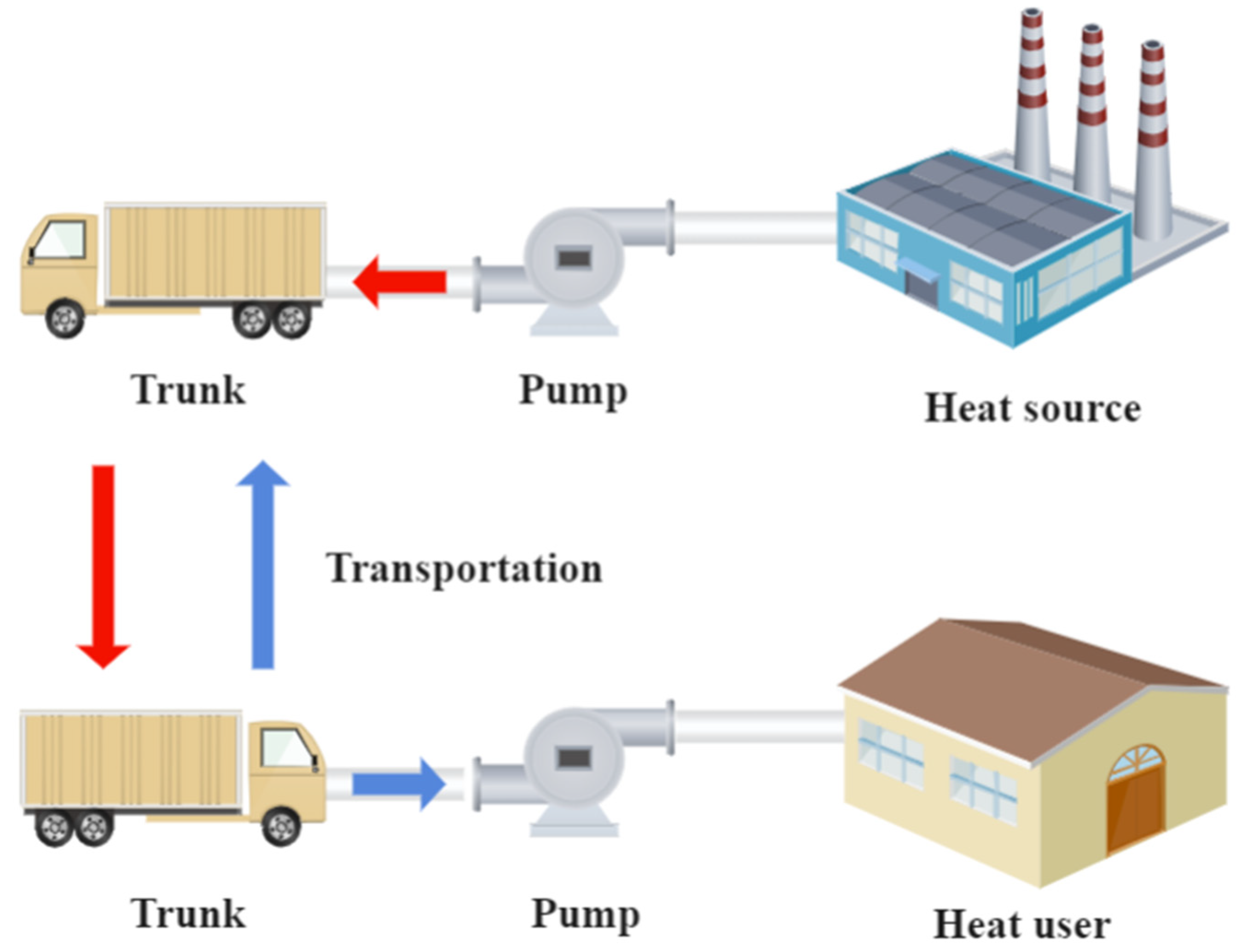
Figure 1. Concept of a mobilized heat storage system (MHSS).
Energies 15 07213 g001
Figure 2. Horizontal TES tube with graded metal foam: (a) pure PCM structure; (b) uniform metal foam structure; (c) gradient foam structure; and (d) representative grid.
Energies 15 07213 g002
Figure 3. Simulation and experimental temperature validation.
Energies 15 07213 g003
Figure 4. Phase transition characteristics for the three structures: (a) liquid phase rate curve with time; (b) unit mass phase transition time.
Energies 15 07213 g004
Figure 5. The maximum heating capacity varies with distance under three structures.
Energies 15 07213 g005
Figure 6. Cost varies with distance under three structures.
Energies 15 07213 g006
Figure 7. The maximum heating capacity varies with distance under different vehicle types.
Energies 15 07213 g007
Figure 8. Cost varies with distance under different vehicle types.
Energies 15 07213 g008
Figure 9. Proportion of total cost.
Energies 15 07213 g009
Table 1. Parameters of simulation for the MHSS.
Mesh IndependenceTotal TimeTime Step IndependenceTotal Time
194,73282000.05 s9150
637,32891500.1 s9150
1,621,62993200.5 s9150
Table 2. Thermophysical properties of materials.
MaterialVariableValue
Paraffin   wax Density ( kg m 3 )850 (solid)/800 (liquid)
Specific   heat   capacity ( J kg 1 K 1 )2000
Thermal   conductivity ( W m 1 K 1 )0.2 (solid)/0.1 (liquid)
Latent heat of fusion ( kJ kg 1 )200
Melting temperature range (°C)46~55
Thermal   expansion   coefficient ( K 1 ) 7.5 × 10 4
Dynamic   viscosity ( kg m 1 s 1 ) 2.51 × 10 3
Copper Density ( kg m 3 )8920
Specific   heat   capacity ( J kg 1 K 1 )380
Thermal   conductivity ( W m 1 K 1 )401
Water Density ( kg m 3 )1000
Specific   heat   capacity ( J kg 1 K 1 )4202
Thermal   conductivity ( W m 1 K 1 )0.56
Dynamic   viscosity ( kg m 1 s 1 ) 2.51 × 10 3
Table 3. Parameters of mobile phase change heat storage system.
ParameterValueParameterValue
PCM (paraffin)8 yuan/kgThe discount rate2.54%
Copper foam20,000 yuan/m3Rate of inflation2.30%
Copper pipe (10 × 0.1)17.9 yuan/mBank annual interest rate4.90%
Installation of water pump and piping50,000 yuanN/AN/A
Table 4. Parameters of transport vehicles.
Transport VehiclePrice (yuan)L × W × HStandard Load (t)Internal Volume (m3)Transportation Costs (yuan/km)
Trunk1100,0006.2 × 2.2 × 2.25301.3
Trunk2140,0007.2 × 2.3 × 2.710450.3
Trunk3170,0009.6 × 2.3 × 2.725600.2
Table 5. Cost and heat storage of three structures.
StructuresInitial Investment
(yuan)
PCM Total Cost
(yuan)
Heat Storage (MJ)
Pure PCM287,598.20397,598.202612476.734
Uniform MF506,421.732316,421.7322352.898
Positive gradient MF506,421.732316,421.7322352.898
Table 6. Cost and heat storage of different transport vehicles.
Transport VehiclePCM Total Cost (yuan)Heat Storage (MJ)Initial Investment (yuan)
Trunk1158,857.251176.45308,857.25
Trunk2316,421.732352.90506,421.73
Trunk3786,827.945882.241,006,827.94
Publisher’s Note: MDPI stays neutral with regard to jurisdictional claims in published maps and institutional affiliations.