Abstract
Modeling the vortex intensification of turbulent heat transfer in narrow engine ducts using single-row dimples was carried out within the framework of multi-block computing technologies implemented in a special VP2/3 package. The cases of a rectangular section with the placement of vortex generators—single-row packages of oval and spherical dimples on the initial hydrodynamic section and the section of the stabilized flow are excluded. The connection between the generated vortex structures and the predominant increase in heat transfer compared to the increase in hydraulic losses for various dimple layouts has been established: zigzag, ladder, and centers shifted and in a longitudinal-transverse order. The superiority in heat removal from the thickness with inclined oval dimples is shown—1.23 times compared to spherical ones with a decay in hydraulic resistance by 1.16 times.
1. Introduction
Energy-efficient surfaces can significantly improve the performance of energy installations, such as heat exchangers [1]. As a rule, a significant (many times and tens of times) increase in relative heat transfer is achieved by applying a wall of ordered protrusions, in particular, by rolling pipes and channels. However, in this case, the relative hydraulic losses grow at a faster rate, and such surfaces structured by protrusions can be used with sufficient total pressure resources. The application of discrete roughness on the surface in the form of ordered concavities or dimples makes it possible to drastically reduce hydraulic losses and provide a high level of heat transfer intensification in multiscale devices [2]. Dimple technologies [3] are increasingly being used in industrial applications, and research is actively continuing to select and justify rational forms of dimples and their layouts. It should be noted that the creation of surfaces with discrete roughness presents significant difficulties and stimulates the use of simple shapes of dimples and protrusions, particularly hemispherical ones. However, the growing possibilities of additive technologies open up prospects for the formation of digitized curvilinear reliefs for new types of energy-efficient surfaces.
The mechanism of heat transfer intensification, as noted in the works of Kiknadze et al. (as can be seen, for example, [4]), is due to the self-organization of jet-vortex flows in hemispherical dimples. The experimental and numerical analysis of vortex heat transfer during separated flow around solitary [5,6,7] and stacked [8,9,10] spherical dimples on the plates and channel walls showed that with an increase in the dimple depth (a spot diameter of up to approximately ), the compaction of staggered and in-line packages, reaching up to of the area of the wetted wall, and a significant (two-fold or more) increase in relative heat transfer are achieved. However, the velocities of the return and secondary flows in the dimples are rather insignificant (in the order of of the characteristic values), and in the zones of separated flow, the heat transfer is much lower than on a flat wall. Thus, spots of low relative heat transfer are observed inside the spherical dimples.
In [11], the shape of an inclined oval dimple of moderate (approximately 2) relative elongation (with respect to width) is proposed. This represents two halves of a spherical dimple connected by a cylindrical trench insert. As a result, we have a groove with hemispherical tips, and the angle of inclination, as a rule, is taken equal to . As it turned out [9,10,11,12], in the separation zones of such dimples, both solitary and single-row, on the plate and on the wall of a narrow channel, in the initial hydrodynamic section and in the stabilized flow section, tornado-like structures arise, causing the intensification of the secondary and return flow.
In [13,14,15,16,17,18], it was found that the relative elongation of the oval dimple has a significant effect on the intensification of the separated flow and heat transfer in solitary and single-row packet dimples on the wall of a narrow channel. In [17,18], the anomalous intensification of turbulent separated flow and heat transfer in an inclined oval-trench dimple is analyzed, which is characterized by a multiple (4–8 times) increase in the maximum absolute values of negative friction and heat transfer in the middle section compared to the corresponding values on the wall of a plane-parallel channel. The maximum velocities of the reverse and secondary swirling flow in the dimple turn out to be of the order of the maximum velocity in a plane-parallel channel.
This article investigates the intensification of turbulent heat transfer in the channel in the initial hydrodynamic section and in the section of a stabilized flow when traditional spherical and proposed oval dimples of moderate elongation are placed on a heated wall. The emphasis is on the analysis of in-line ensembles of holes with their different arrangements: zigzag, ladder, with a shift in the centers of the dimples, and in a longitudinal-transverse order.
2. Numerical Model and Its Verification
2.1. Mathematical and Discrete Models
Vortex heat transfer during the turbulent motion of a viscous incompressible fluid in a narrow channel with applied dimples is described by a system of Reynolds equations closed using Menter’s [19] shear stress transfer (MSST) model equations and an energy equation. The original system of equations is solved using multiblock computing technologies implemented in the VP2/3 [20] package. The finite volume method [21] is the basis for solving the linearized equations of fluid dynamics, the transfer of turbulent characteristics, and energy. The SIMPLEC method was applied to solve the problem [22]. The Rhee–Chow monotonizer [23], modified in [24], is used in the pressure correction block for centered structured grids with dependent variables located at the centers of computational cells. The incremental discretization scheme is applied, and in the explicit part of the transport equations, the convective terms of the equations of fluid dynamics are approximated by the Leonard [25] scheme, and in the transport equations of turbulent characteristics, by the Van Leer scheme [26]. To prevent non-physical oscillations in the reproduction of flows with thin shear layers, the artificial diffusion mechanism is introduced into the implicit part of the equations in combination with the use of one-sided upwind schemes for discretizing the convective terms. The conjugate gradient method is used to solve discretized equations [27]. To accelerate the convergence of iterations in the pressure correction block, the Demidov algebraic convergence accelerator [28] is used.
Several tasks are solved. Similarly to [12], we consider the flow and heat transfer in a narrow channel with 15 single-row spherical and 15 oval dimples arranged in a zigzag pattern with slope angles of . The diameter of the spherical dimple, equal to the width of the oval dimple, the maximum flow rate, and temperature K in the inlet section are taken as characteristic parameters. The geometric dimensions of the plane-parallel channel are as follows: length , height , and width . The origin of the Cartesian coordinate system is located in the middle of the inlet section of the channel on the wall (Figure 1a).
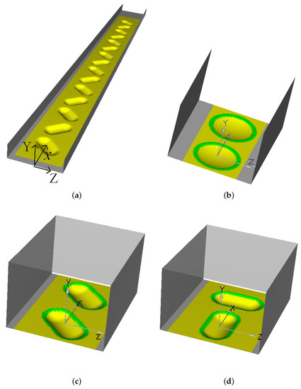
Figure 1.
A long channel (a) with the 15 zigzag oval dimples applied to the bottom wall (with the top wall removed) and periodic sections of the channel with two spherical (b) and two oval dimples when they are arranged as a ladder at an angle of (c) and longitudinal-transverse placement (d).
Furthermore, two reliefs are compared, consisting of spherical and oval dimples (with a cylindrical insert length of ), applied with a step of . Their depth () is and the rounding radius (r) is . The density of the first ensemble of spherical dimples is , and that of the second is . The integral and local characteristics of channels with dimples are normalized according to similar parameters for a channel with plane-parallel walls.
In the inlet section, following [12], the flow parameters in the near-wall layer are determined corresponding to the chosen thickness of the boundary layer (). Turbulence intensity in the core of the flow is set low (). In the outlet section, the flow and heat transfer characteristics are calculated using the solution continuation conditions or soft boundary conditions. No-slip conditions are imposed on the walls. The bottom wall, heated to 373 K, and the top wall, maintained at “room” temperature, are assumed to be isothermal, while the side walls are thermally insulated. Air is considered as a coolant (), and the Reynolds number is assumed to be .
The calculations of flows of different scales are carried out on multi-block multilevel grids with their mutual intersection. A novel procedure for interpolating parameters in the area of joining nodes with a different grid structure is formulated, which ensures proper conservatism in solving problems. The developed factorized algorithm is generalized to the case of multiblock computational grids within the framework of the concept of decomposition of the computational domain and the generation of oblique grids with overlapping in the selected significantly different-scale subdomains. The transfer of values between intersecting grids within the framework of a multi-block grid strategy is carried out using non-conservative linear interpolation. The cell volume of the selected structured grid is divided into six pyramids with one of the faces as the base and the cell center as the vertex. Each of the pyramids, in turn, is divided into eight tetrahedra. In the process of intergrid interpolation, it is determined that the selected point, at which it is necessary to determine the set of parameters, belongs to one of the tetrahedra that form the cell, and a linear interpolation is built for it using known values at the vertices. The equivalence of the proposed method and the known method of conservative interpolation [20] is shown. Approved computational algorithms of algebraic and elliptic type are used to construct curvilinear grids consistent with the boundaries.
To solve the problem, a computational grid is used, which consists of two blocks and contains approximately 2.7 million cells. Dimple boundaries are not distinguished, and they are considered as part of the relief.
The problem of heat transfer in a periodic channel section with two spherical and oval dimples (Figure 1b–d) is stated as in [12]. The asymptotic characteristics of heat transfer and hydraulic losses of dimpled channels are calculated on a stabilized section of the flow and heat transfer. We consider spherical dimples located in a corridor stack and a stack with eccentricity relative to the longitudinal middle section of the channel, as well as several ordered structures of oval dimples: single-row inclined dimples oriented at an angle of , oval dimples arranged in a zigzag with slope angles of , and combinations of longitudinal-transverse pairs of oval dimples (Figure 1b,c). The parameters in the inlet and outlet sections are determined from the periodicity condition. On the walls, the characteristics are determined in the same way as in the first problem. When solving, the procedures for correcting pressure and mass-average temperature are used, following [12,20]. It should be noted the thematic proximity of the problems being solved with the problem of heat transfer intensification on periodic protrusions [29]. The good agreement between the calculated and measured characteristics presented in it confirm the acceptability of the chosen semi-empirical turbulence model.
In [6,10,16,30,31,32], the results of a comparison of numerical predictions obtained using SST models with experimental data on separated flow and heat transfer in channels and on plates with solitary and stacked spherical and inclined oval dimples are presented. They also confirm the acceptability of the SST model [19] for calculating convective heat transfer in intense separated and vortex flows.
2.2. Verification of the Numerical Method and Turbulence Model
The flow around a solitary oval-trench dimple on the wall of a plane-parallel channel is considered. On the experimental stand of the Institute of Mechanics of Moscow State University [33], with a width of m, a height of m and a length of m, measurements of the static pressure distributions on the surface of a dimple m wide and a relative length of 5, a depth of (in ratio of the width) were measured at various angles of inclination in the range of change from to . Dimples with a sharp edge are located in the middle of the channel at a distance of m from the inlet section. The Reynolds number determined from the flow velocity and channel height is . The thickness of the boundary layer at the entrance to the working section of the channel is in ratio of the channel height, and the turbulence of the oncoming flow in the channel core is .
The numerical analogue of the experimental channel has dimensions of . At the channel inlet, a uniform flow is set with a boundary layer thickness equal to the experimental value of . The numerical method and the selected turbulence model were tested on an oval trench hole with a width of , an elongation of , a depth of , and sharp edges rounded along a radius of . The angle of inclination of the hole is . The center of the hole is located at a distance of from the inlet section.
A block computational grid is considered, consisting of two block grids (Figure 2a). The first Cartesian grid is built in a plane-parallel channel. It contains approximately million cells, which thicken as they approach the walls. In the central part of the channel, the grid steps are uniform in the longitudinal and transverse directions and equal to . Inside the channel grid, there is a curvilinear grid, coordinated with the surface of the dimple, on the heated lower wall of the channel, a block grid covering the area of the dimple. The specified area has dimensions of , in the center of which is the center of the dimple. In the longitudinal and transverse directions, the grid is uniform with a step of . The number of cells in the curvilinear grid adjacent to the well is approximately million. The near-wall steps of the considered grids near the walls are .
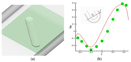
Figure 2.
Two-part block grid (a) and comparison of the dependences of the static pressure coefficient (b) in the joint section of the dimple (line—calculation; dots—experiment [33]).
Figure 2b compares the numerical predictions and experimental data obtained in [33] on the distribution of the static pressure coefficient in the section of the joint of the hemispherical segment of the dimple and its trench part, in which an extraordinary pressure drop is observed. Good agreement between the results indicates the acceptable accuracy of the calculation method, as well as the adequacy of the RANS approach and the selected modified SST turbulence model.
3. The Discussion of the Results
3.1. Intensification of Heat Transfer in a Narrow Channel with 15 Spherical and Oval Dimples on a Heated Wall
Figure 3 and Figure 4 and Table 1 show some of the numerical results obtained. Index stands for plane, index –averaged results over wetter area of dimple.
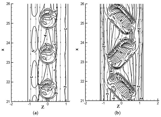
Figure 3.
Spreading patterns and fields of relative, local heat transfer on the last three dimples in a channel with 15 spherical (a) and oval (b) dimples. 1—; 2—; 3—; 4—; 5—; 6—; 7—; 8—; 9—; 10—; 11—.
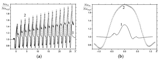
Figure 4.
Averaged relative heat transfer in longitudinal (a) and transverse (b) directions for spherical (1) and oval (2) dimples.

Table 1.
Comparison of the relative total heat transfer, hydraulic losses, and thermal-hydraulic efficiency (THE) of 15-dimple reliefs.
The local Nusselt numbers on wetted curved surfaces referred to the Nusselt numbers on the wall of a plane-parallel channel (in the corresponding projections), are considered. The relative Nusselt numbers and averaged over the transverse and longitudinal strips of the dimpled area are also compared, respectively. Furthermore, finally, the thermal efficiency of the dimpled section of the channel is characterized by the relative total heat loss , determined over the entire area of the heated surface being wetted.
The oval dimples are arranged in zigzag (Figure 1a) to cause an alternate change in the direction of flow in the near-wall layer. For single-row spherical dimples, the synchronization of vortex structures is observed similarly to the multirow ordered dimples [9]. The proposed type of arrangement of oval dimples makes it possible to organize a stable secondary movement with the variable direction of the generated swirling jets towards the side walls. There is a significant increase (Figure 3) of local heat transfer as you move from dimple to dimple, and one cannot talk about the asymptotic behavior of for this arrangement. It should be noted that, for approximately identical rows with dimples, the thermal-hydraulic efficiency (THE) of a channel with spherical dimples turns out to be somewhat less than 1, while for a channel with oval dimples, the relative heat transfer significantly exceeds the relative hydraulic losses.
3.2. Asymptotic Thermal-Hydraulic Characteristics of Channels with Dimples in a Stabilized Hydrodynamic Section
The problem of the thermal design of dimpled reliefs is largely associated with the organization of the desired structure of the vortex near-wall flow, which determines the outstripping growth of the heat transfer from the wall compared to the increase in hydraulic losses. As mentioned earlier, the search for such reliefs can be based on the use of oval dimples oriented at an angle to the oncoming flow.
The length of the cylindrical insertion of the oval dimples is 1. The channel is narrow with a height of . Below are the results for dimples deep (see Table 2). is a width of a channel. Reynolds number . The coolant is air. The temperature of the heated wall with dimples is 373 K, and the upper wall is maintained at room temperature (293 K). The side walls are thermally insulated.
Table 2.
Comparison of the heat transfer, hydraulic losses, and thermal-hydraulic efficiency of a channel section with two dimples.
The pressure fields shown in Figure 5 with spreading patterns confirm the implementation of that desired from the point of view of heat transfer intensification in the near-wall layer of the tornado flow structure. As it turned out, for such a relief geometry, the near-wall flow has a wavy oscillatory character with respect to the oncoming flow. Thus, the secondary flow sways from wall to wall, causing a significant intensification of the heat and mass transfer processes (Figure 6). However, a row of spherical dimples creates a field of synchronized vortex structures inclined to one side from the oncoming flow.
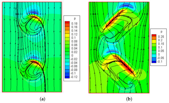
Figure 5.
Comparison of patterns of coolant spreading along the wall with spherical (a) and oval (b) dimples with applied pressure fields.
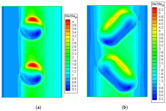
Figure 6.
Comparison of relative Nusselt number fields on the wall with spherical (a) and oval (b) dimples in the periodic module.
The comparisons indicated in Figure 6 and Figure 7 indicate an approximately -fold excess of the maximum heat transfer coefficients from the oval-trench holes compared to traditional spherical traditional ones.
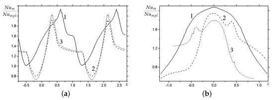
Figure 7.
Relative heat transfer averaged over a strip with dimples in the longitudinal (a) and transverse (b) directions for oval (1) and spherical (2, 3) dimples. 1, 2—; 3—.
Table 2 compares the results of the integral characteristics of heat transfer calculations in three-dimensional and two-dimensional flows in three-dimensional and flat channels with single-row dimples and trenches of the same depth. In the latter case, the two-dimensional problem is solved similarly to [34].
The heat transfer from the wall with oval-trench dimples was -fold superior to that of the spherical ones with a decay in hydraulic resistance of (see Table 3).
Table 3.
Comparison of the heat transfer, hydraulic losses, and thermal-hydraulic efficiency of a channel section with two trench dimples.
Figure 8, Figure 9, Figure 10, Figure 11, Figure 12, Figure 13 and Figure 14 and Table 4 and Table 5 present the results of calculations of turbulent heat transfer in the flow around the oval and spherical dimples of different depths ( and ). For spherical dimples, a rearrangement of the flow pattern is observed with a decrease in their depth (from a single tornado to two symmetrical vortex cells), which is accompanied by a significant decrease in heat transfer from the dimpled area. The flow pattern around oval dimples on the channel wall does not change significantly. Inclined elongated dimples generate tornado-like eddies, although their intensity decreases with decreasing depth. As a result, the heat transfer from the wall with dimples rapidly decreases when going from to , although the superiority of oval dimples over spherical ones is retained.
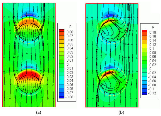
Figure 8.
Comparison of patterns of coolant spreading over the wall with spherical dimples (a) and (b) deep with applied pressure fields.
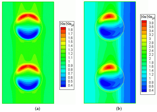
Figure 9.
Comparison of fields of relative Nusselt numbers for reliefs with spherical dimples (a) and (b) deep.
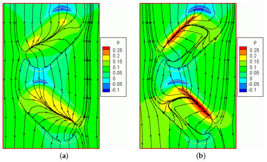
Figure 10.
Comparison of patterns of coolant spreading over the wall with oval dimples (a) and (b) deep with applied pressure fields.
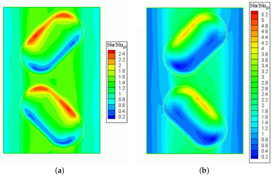
Figure 11.
Comparison of fields of relative Nusselt numbers for reliefs with oval dimples (a) and (b) deep.
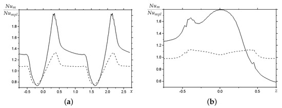
Figure 12.
Comparison of band-averaged relative (a) and (b) with spherical dimples. The solid lines are and the dashed lines are .
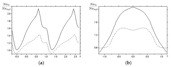
Figure 13.
Comparison of band-averaged distributions with oval dimples of relative (a) and (b). The solid lines are and the dashed lines are .
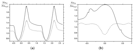
Figure 14.
Comparison of band-averaged distributions with spherical dimples of relative (a) and (b). Solid lines are dimples without displacement, and dashed lines are with a displacement of from the longitudinal axis.
Table 4.
Comparison of the heat transfer, hydraulic losses, and thermal-hydraulic efficiency of a channel section with two spherical dimples.
Table 5.
Comparison of the heat transfer, hydraulic losses, and thermal-hydraulic efficiency of a channel section with two dimples deep.
It could be expected that the transverse alternating displacement of the centers of spherical dimples will cause an increase in the intensification of heat transfer in the channel, since in this case, the structure of the near-wall flow becomes similar to that observed for oval dimples with their zigzag arrangement. However, this did not happen. As follows from Figure 15 and Figure 16 and Table 5, a significant shift () causes the expected change in the flow pattern, which is accompanied not by an increase, however, on the contrary, by a significant decrease in heat transfer intensification. In general, the thermal-hydraulic efficiency of the dimpled area turned out to be lower than for the coaxial arrangement of spherical dimples. Hence, we can conclude that the initial assumption about the most desirable flow regime, which produces the oscillatory motion of the coolant in the near-wall zone relative to the direction of the external flow, which is not entirely correct, and that means that further searches for a rational placement of dimples in the package are reasonable.
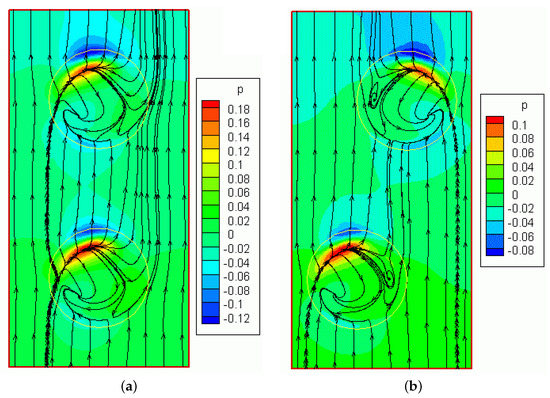
Figure 15.
Comparison of patterns of coolant spreading over the wall with spherical dimples deep without displacement (a) and with displacement (b) with applied pressure fields.
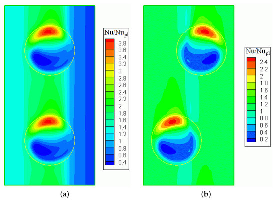
Figure 16.
Comparison of the fields of relative Nusselt numbers for reliefs with spherical dimples without displacement (a) and with displacement of their centers (b).
3.3. Comparison of Characteristics of Sections with Oval Dimples in Different Arrangements
The given rectangular channel has a cross-section with dimensions of . The base Reynolds number is . The Prandtl number is . The lower and upper walls of the channel are isothermal with temperatures of 373 K and 293 K. The side walls are thermally insulated. The length of the calculated section corresponds to the density of dimples, equal to .
As the sections of dimples on the lower wall of the channel are compared, the most preferred oval dimples from methodological studies are selected, and in addition to the location of the ladder, the longitudinal-transverse placement of the dimples is considered (Figure 1c,d). The length of the cylindrical insert is and the rounding radius is , chosen according to the results of methodical experiments. The dimple section density of was also tested on numerous examples. The base depth of the dimples is , however, for comparison, some calculations are made for a dimple with a shallower depth of .
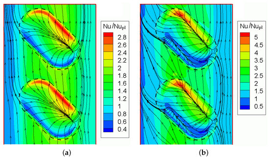
Figure 17.
Comparison of relative Nusselt number fields on the lower wall of the dimpled channel with plotted spreading patterns for depths of (a) and (b).
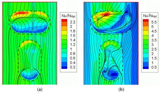
Figure 18.
Comparison of relative Nusselt number fields on the lower wall of the dimpled channel with spreading patterns for depths of (a) and (b).
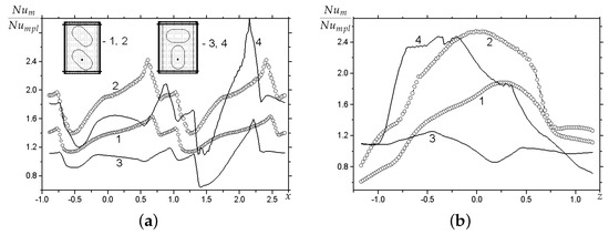
Figure 19.
Relative heat transfer averaged over the area strip with dimples in the longitudinal (a) and transverse (b) directions for ladder arrangement (1, 2) and longitudinal-transverse arrangement (3, 4). .
Table 6.
Comparison of heat transfer, hydraulic losses, and thermal-hydraulic efficiency for channels with a different arrangement of dimples on the bottom wall.
It was established that the mutual arrangement of oval dimples has a significant effect on the pattern of their vortex flow and on thermal loads. The interference of vortex structures contributes to the intensification of the separated flow and heat transfer, especially in deep dimples.
Small dimples are not preferable in terms of vortex heat transfer intensification, although the hydraulic losses for them are the smallest, which leads to a high thermal-hydraulic efficiency of dimple packs. In principle, oval dimples with a ladder, even at a depth of , allow one to obtain a fairly significant increase in heat transfer.
Dimples deep are recommended for use. This selected depth makes it possible to intensify the flow and heat exchange with the proper location of the oval dimple. It is interesting to note that the longitudinal-transverse placement of the deep dimples does not differ much in terms of thermal and hydraulic characteristics from the recommended arrangement of the ladder. In general, a 2-fold increase in heat transfer from the lower wall of the channel is predicted compared to the wall of a smooth channel.
4. Conclusions
The numerical modeling of vortex heat transfer intensification in a narrow channel with one longitudinal row of ordered dimples was carried out, and an effective zigzag layout of trench dimples was proposed. This scheme with trench dimples was shown to have significant advantages over spherical dimples.
The calculations of heat transfer in a channel with 15 zigzag dimples in the initial hydrodynamic section of the channel confirmed the progressive increase in heat transfer on the heated wall as the number of dimples in a single row increased. It is noted that the process of increasing heat transfer does not reach the asymptotics for a given channel length. A significant superiority of oval dimples over traditional spherical dimples in terms of thermal efficiency ( versus ) was substantiated, and the thermal-hydraulic efficiency of a channel with spherical dimples is less than 1.
Based on the analysis of the periodic computational node, the asymptotic thermal-hydraulic characteristics of a channel with a relief are determined for an unlimited number of single-row dimples and their different arrangements.
The superiority in heat loss from the wall with inclined oval-trench dimples located in a zigzag was found to be times higher compared to spherical ones ( versus approximately ) with a decay in hydraulic resistance by times.
Dimples with a depth of are much more preferable to dimples with a depth of , although oval dimples with a ladder arrangement, even at a depth of , enable one to obtain a rather significant increase in heat transfer.
In general, for rather moderate depths of inclined oval dimples (approximately ), a two-fold increase in heat loss from the lower channel wall is predicted compared to the smooth channel wall.
Author Contributions
Conceptualization, S.I. and A.S.; methodology, S.I.; software, A.S.; validation, N.T.; investigation, L.I.; resources, V.K.; data curation, A.U.; writing—original draft preparation, S.I.; writing—review and editing, N.T.; visualization, N.T.; project administration, D.N. All authors have read and agreed to the published version of the manuscript.
Funding
The research was funded by the Ministry of Education and Science of the Russian Federation within the framework of the Program of the World-Class Science Center “Advanced Digital Technologies” (agreement dated 16 November 2020, No. 075-15-2020-903).
Conflicts of Interest
The authors declare no conflict of interest.
References
- Kalinin, E.K.; Dreitser, G.A.; Kopp, I.Z.; Myakochin, A.S.; Janna, W.S. Efficient Surfaces for Heat Exchangers: Fundamentals and Design. Appl. Mech. Rev. 2002, 55, B78–B79. [Google Scholar] [CrossRef]
- Dzyubenko, B.; Kuzma-Kichta, Y.; Leontiev, A.; Fedik, I.; Kholpanov, L. Intensification of Heat and Mass Transfer on Macro-, Micro-, and Nanoscales; Begell House: New York, NY, USA, 2016. [Google Scholar]
- Rashidi, S.; Hormozi, F.; Sundén, B.; Mahian, O. Energy saving in thermal energy systems using dimpled surface technology—A review on mechanisms and applications. Appl. Energy 2019, 250, 1491–1547. [Google Scholar] [CrossRef]
- Kiknadze, G.I.; Gachechiladze, I.A.; Gorodkov, A.Y. Self-Organization of Tornado-Like Jets in Flows of Gases and Liquids and the Technologies Utilizing This Phenomenon. In Proceedings of the HT2009, San Francisco, CA, USA, 19–23 July 2009; pp. 547–560. [Google Scholar] [CrossRef]
- Terekhov, V.I.; Kalinina, S.V.; Mshvidobadze, Y.M. Heat Transfer Coefficient and Aerodynamic Resistance on a Surface with a Single Dimple. J. Enhanc. Heat Transf. 1997, 4, 131–145. [Google Scholar] [CrossRef]
- Isaev, S.; Kornev, N.; Leontiev, A.; Hassel, E. Influence of the Reynolds number and the spherical dimple depth on turbulent heat transfer and hydraulic loss in a narrow channel. Int. J. Heat Mass Transf. 2010, 53, 178–197. [Google Scholar] [CrossRef]
- Isaev, S.; Schelchkov, A.; Leontiev, A.; Baranov, P.; Gulcova, M. Numerical simulation of the turbulent air flow in the narrow channel with a heated wall and a spherical dimple placed on it for vortex heat transfer enhancement depending on the dimple depth. Int. J. Heat Mass Transf. 2016, 94, 426–448. [Google Scholar] [CrossRef]
- Turnow, J.; Kornev, N.; Zhdanov, V.; Hassel, E. Flow structures and heat transfer on dimples in a staggered arrangement. Int. J. Heat Fluid Flow 2012, 35, 168–175. [Google Scholar] [CrossRef]
- Isaev, S.A.; Leont’ev, A.I.; Baranov, P.A. Simulating tornado-like enhancement of heat transfer under low-velocity motion of air in a rectangular dimpled channel. Part 2: Results of parametric studies. Therm. Eng. 2007, 54, 655–663. [Google Scholar] [CrossRef]
- Isaev, S.A.; Leontiev, A.I. Problems of simulating tornado-like heat transfer in turbulent flow past a dimpled relief on a narrow channel wall. J. Eng. Phys. Thermophys. 2010, 83, 783–793. [Google Scholar] [CrossRef]
- Isaev, S.A.; Leont’ev, A.I.; Mityakov, A.V.; Pyshnyi, I.A.; Usachov, A.E. Intensification of Tornado Turbulent Heat Exchange in Asymmetric Holes on a Plane Wall. J. Eng. Phys. Thermophys. 2003, 76, 266–270. [Google Scholar] [CrossRef]
- Isaev, S.A.; Leontiev, A.I.; Kornev, N.V.; Hassel, E.; Chudnovskii, Y.P. Heat transfer intensification for laminar and turbulent flows in a narrow channel with one-row oval dimples. High Temp. 2015, 53, 375–386. [Google Scholar] [CrossRef]
- Isaev, S.A.; Leontiev, A.I.; Gul’tsova, M.E.; Popov, I.A. Transformation and intensification of tornado-like flow in a narrow channel during elongation of an oval dimple with constant area. Tech. Phys. Lett. 2015, 41, 606–609. [Google Scholar] [CrossRef]
- Isaev, S.; Schelchkov, A.; Leontiev, A.; Gortyshov, Y.F.; Baranov, P.; Popov, I. Vortex heat transfer enhancement in the narrow plane-parallel channel with the oval-trench dimple of fixed depth and spot area. Int. J. Heat Mass Transf. 2017, 109, 40–62. [Google Scholar] [CrossRef]
- Isaev, S.A.; Leontiev, A.I.; Chudnovsky, Y.; Popov, I.A. Vortex heat transfer enhancement in narrow channels with a single oval-trench dimple oriented at different angles to the flow. J. Enhanc. Heat Transf. 2018, 25, 579–604. [Google Scholar] [CrossRef]
- Isaev, S.; Leontiev, A.; Chudnovsky, Y.; Nikushchenko, D.; Popov, I.; Sudakov, A. Simulation of Vortex Heat Transfer Enhancement in the Turbulent Water Flow in the Narrow Plane-Parallel Channel with an Inclined Oval-trench Dimple of Fixed Depth and Spot Area. Energies 2019, 12, 1296. [Google Scholar] [CrossRef]
- Isaev, S.A.; Gritckevich, M.S.; Leontiev, A.I.; Popov, I.A.; Sudakov, A.G. Anomalous Intensification of a Turbulent Separated Flow in Inclined, Single-Row, Oval-Trench Dimples on the Wall of a Narrow Channel. High Temp. 2019, 57, 771–774. [Google Scholar] [CrossRef]
- Isaev, S.A.; Leont’ev, A.I.; Nikushchenko, D.V.; Sudakov, A.G.; Usachov, A.E. Intensification of the Detached Flow in a Single Row of Inclined Oval Trench Dimples on the Wall of a Narrow Channel. J. Eng. Phys. Thermophys. 2021, 94, 151–159. [Google Scholar] [CrossRef]
- Menter, F. Zonal Two Equation k-w Turbulence Models For Aerodynamic Flows. In Proceedings of the 23rd Fluid Dynamics, Plasmadynamics, and Lasers Conference, Orlando, FL, USA, 6–9 July 1993. [Google Scholar] [CrossRef]
- Isaev, S.; Baranov, P.; Usachov, A. Multiblock Computational Technologies in the VP2/3 Package on Aerothermo-Dynamics; LAP LAMBERT Academic Publishing: Saarbrucken, Germany, 2013. [Google Scholar]
- Ferziger, J.H.; Perić, M. Computational Methods for Fluid Dynamics, 2nd ed.; Springer: Berlin, Germany, 1999. [Google Scholar]
- Van Doormaal, J.P.; Raithby, G.D. Enhancements of the simple method for predicting incompressible fluid flows. Numer. Heat Transf. 1984, 7, 147–163. [Google Scholar] [CrossRef]
- Rhie, C.M.; Chow, W.L. Numerical study of the turbulent flow past an airfoil with trailing edge separation. AIAA J. 1983, 21, 1525–1532. [Google Scholar] [CrossRef]
- Pascau, A.; Garcia-Polanco, N. Consistency of simplec scheme in collocated grids. In Proceedings of the V European Conference on Computational Fluid Dynamics, Lisbon, Portugal, 14–17 June 2010. [Google Scholar]
- Leonard, B. A stable and accurate convective modelling procedure based on quadratic upstream interpolation. Comput. Methods Appl. Mech. Eng. 1979, 19, 59–98. [Google Scholar] [CrossRef]
- van Leer, B. Towards the ultimate conservative difference scheme. V. A second-order sequel to Godunov’s method. J. Comput. Phys. 1979, 32, 101–136. [Google Scholar] [CrossRef]
- Saad, Y. Iterative Methods for Sparse Linear Systems, 2nd ed.; Society for Industrial and Applied Mathematics: Philadelphia, PA, USA, 2003. [Google Scholar]
- Demidov, D. AMGCL —A C++ library for efficient solution of large sparse linear systems. Softw. Impacts 2020, 6, 100037. [Google Scholar] [CrossRef]
- Dreitser, G.A.; Isaev, S.A.; Lobanov, I.E. Calculation of convective heat transfer in a pipe with periodically arranged surface vortex generators. High Temp. 2005, 43, 214–221. [Google Scholar] [CrossRef]
- Isaev, S. Genesis of anomalous intensification of separation flow and heat transfer in inclined grooves on structured surfaces. Fluid Dyn. 2022, 57, 558–570. [Google Scholar] [CrossRef]
- Isaev, S.; Nikushchenko, D.; Sudakov, A.; Tryaskin, N.; Egorova, A.; Iunakov, L.; Usachov, A.; Kharchenko, V. Standard and Modified SST Models with the Consideration of the Streamline Curvature for Separated Flow Calculation in a Narrow Channel with a Conical Dimple on the Heated Wall. Energies 2021, 14, 5038. [Google Scholar] [CrossRef]
- Isaev, S.; Nikushchenko, D.; Sudakov, A.; Tryaskin, N.; Egorova, A.; Iunakov, L.; Usachov, A.; Kharchenko, V. Numerical Simulation of a Periodic Quasi-Switching Mode of Flow around a Conical Dimple with a Slope Angle of 10 Degrees on the Wall of a Narrow Channel Using URANS. Fluids 2021, 6, 385. [Google Scholar] [CrossRef]
- Zubin, M.A.; Zubkov, A.F. Structure of Separation Flow Past a Cylindrical Cavity in the Wall of a Plane Channel. Fluid Dynamics. 2022, 57, 77–85. [Google Scholar] [CrossRef]
- Isaev, S.A.; Leontev, A.I.; Kiknadze, G.I.; Kudryavtsev, N.A.; Gachechiladze, I.A. Comparative Analysis of the Vortex Heat Exchange in Turbulent Flows around a Spherical Hole and a Two-Dimensional Trench on a Plane Wall. J. Eng. Phys. Thermophys. 2005, 78, 749–761. [Google Scholar] [CrossRef]
Publisher’s Note: MDPI stays neutral with regard to jurisdictional claims in published maps and institutional affiliations. |
© 2022 by the authors. Licensee MDPI, Basel, Switzerland. This article is an open access article distributed under the terms and conditions of the Creative Commons Attribution (CC BY) license (https://creativecommons.org/licenses/by/4.0/).