

Research on Collaborative Design of Performance-Refined Zero Energy Building: A Case Study


Abstract
:
1. Introduction
2. Literature Review
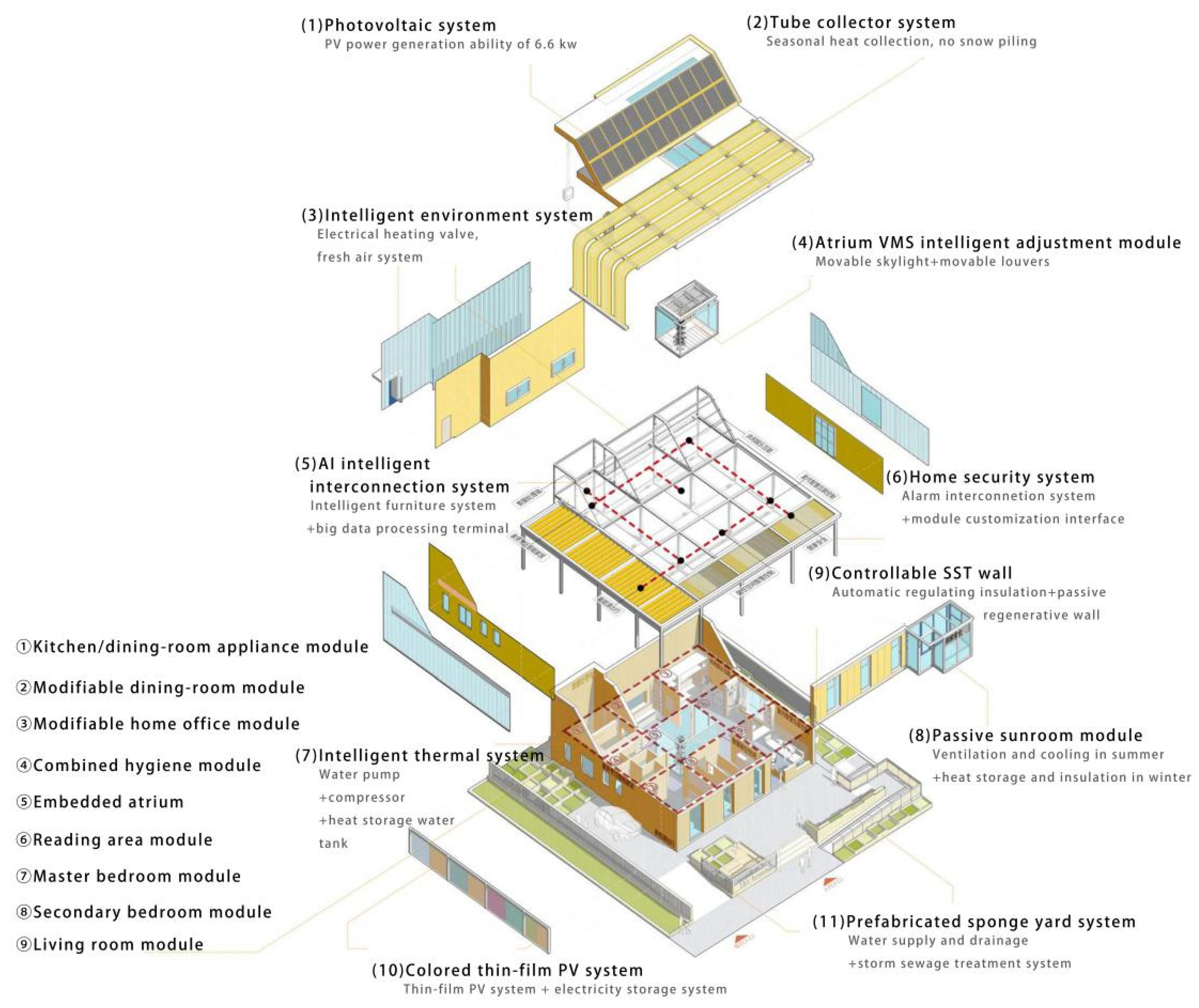
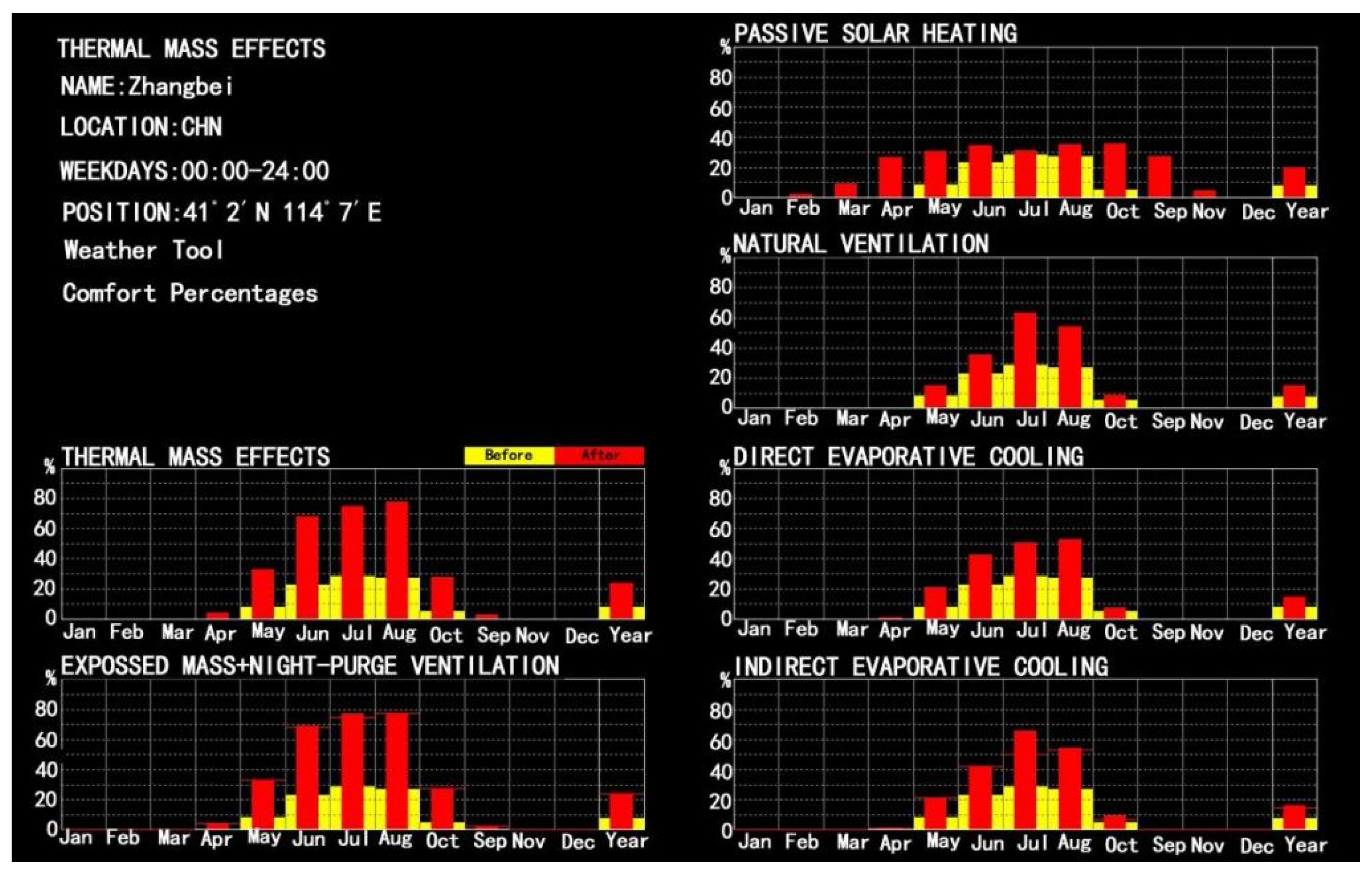
3. T&A House’s Technical Strategies to Achieve Zero Energy Consumption
4. Collaborative Design Method for T&A House
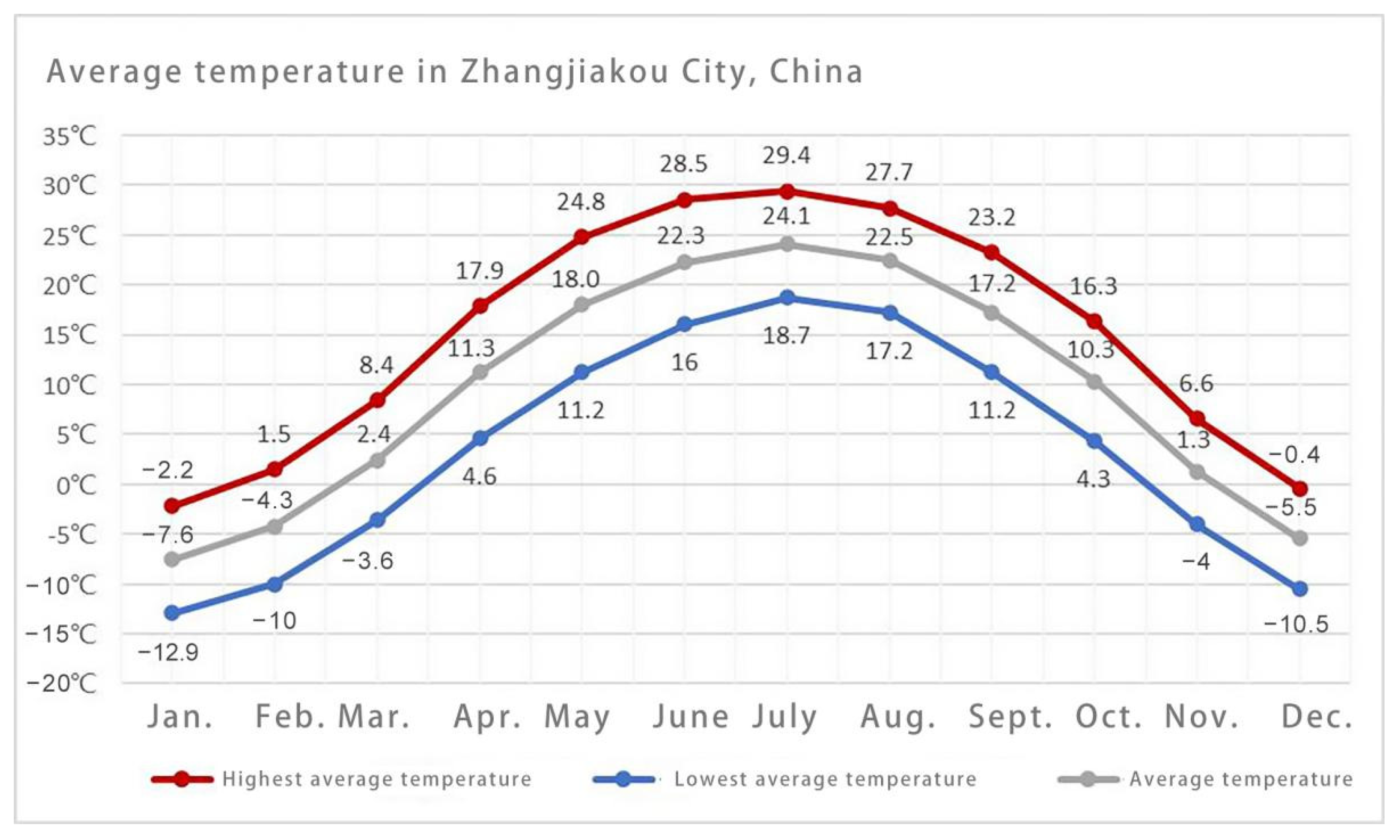
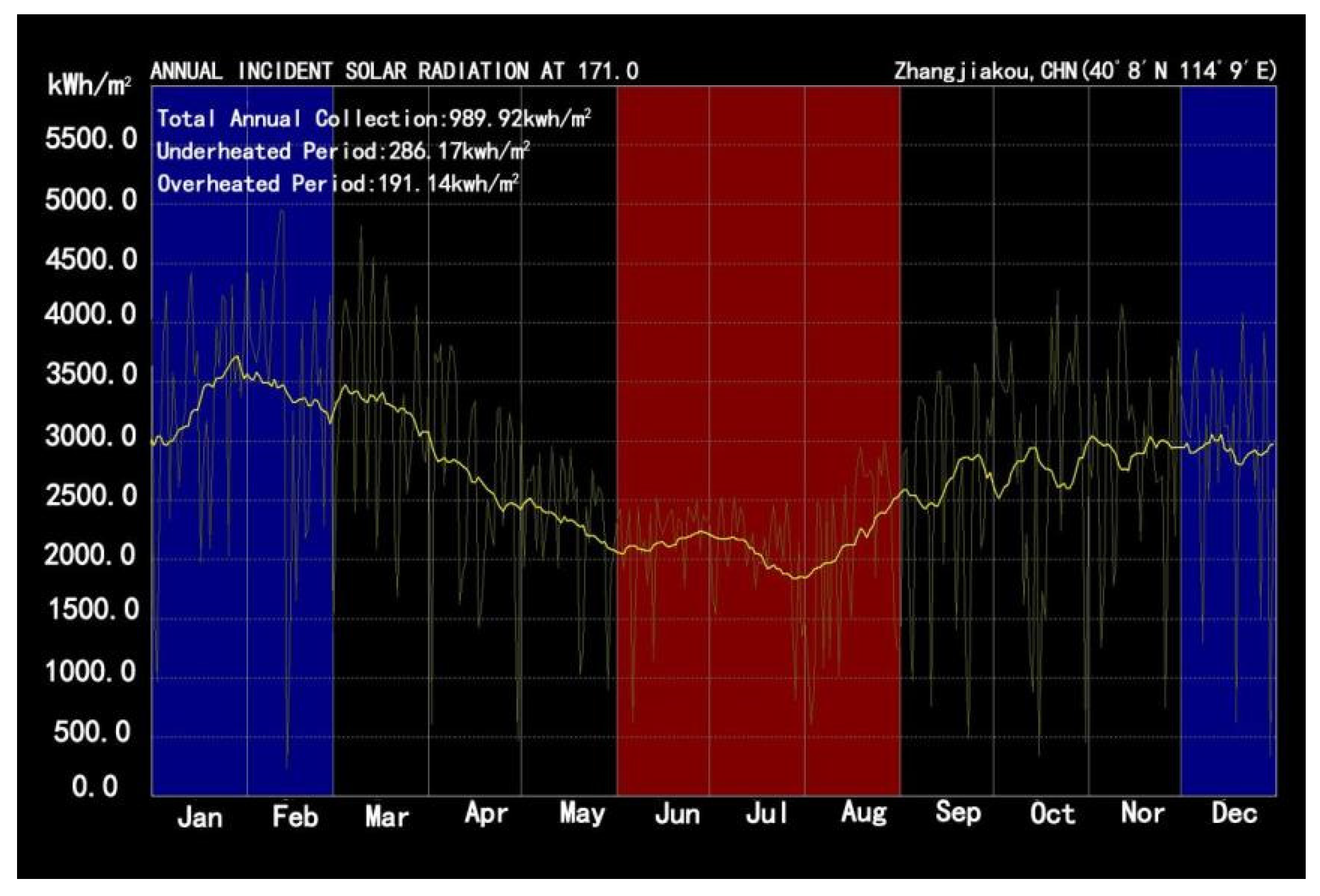
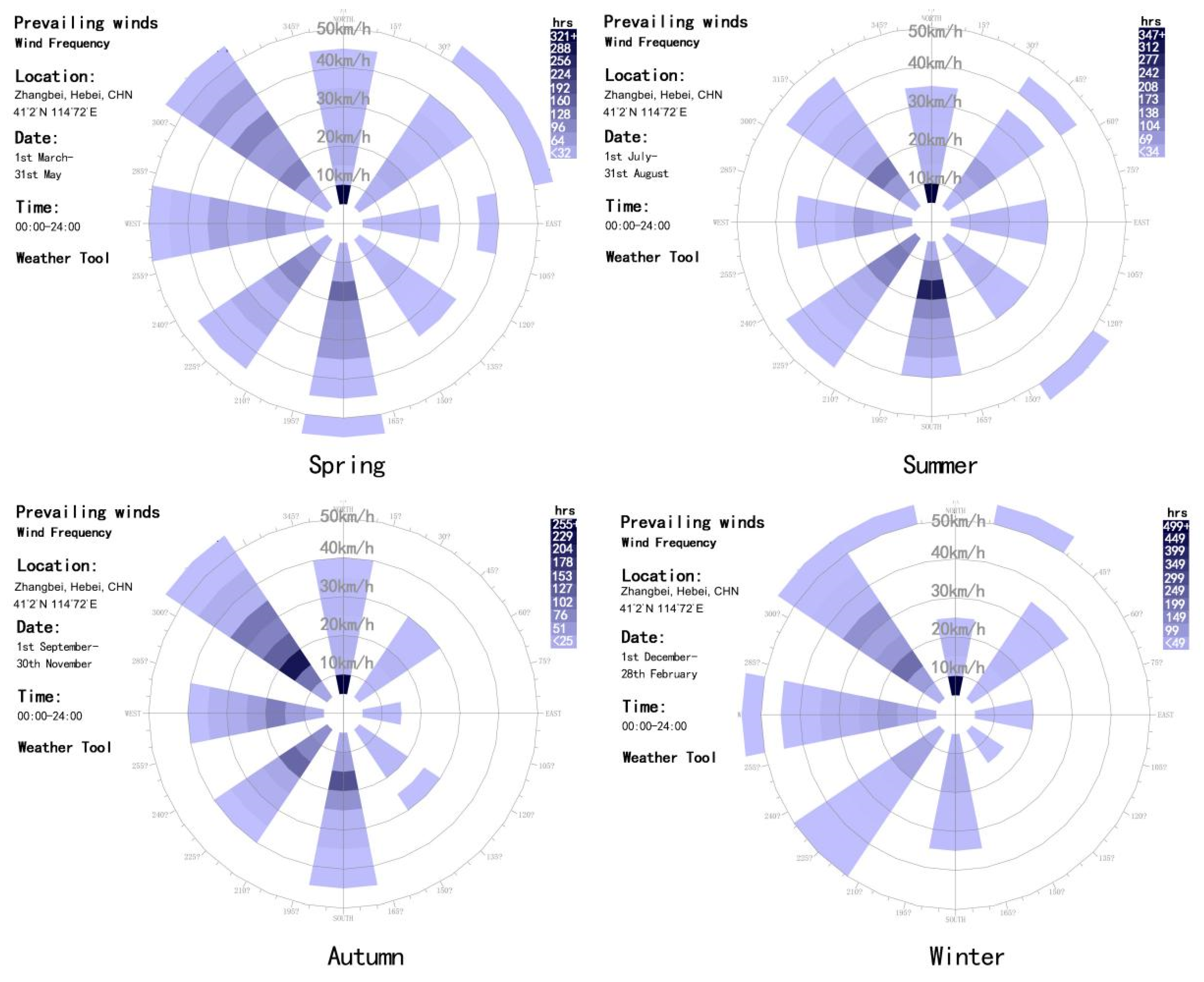
4.1. Collaboration-Oriented Passive Design
- (1)
- Temperature
- (2)
- Humidity
- (3)
- Sunshine
- (4)
- Wind conditions
4.2. Collaborative Design in the Scheme Generation Stage
4.2.1. Collaborative Passive Design in the Stage of Environment Planning
4.2.2. Collaborative Passive Design in the Stage of Shape Design
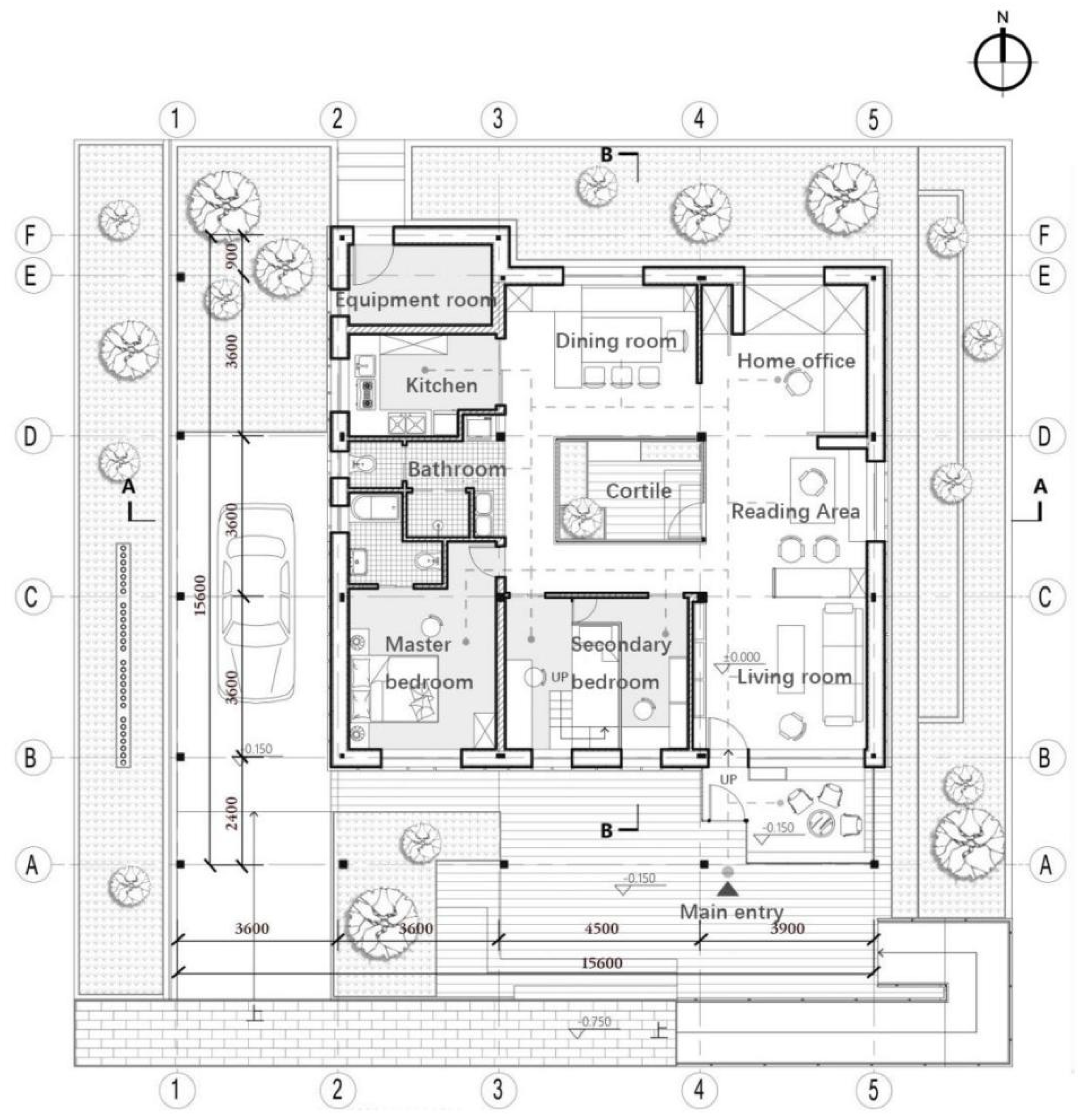
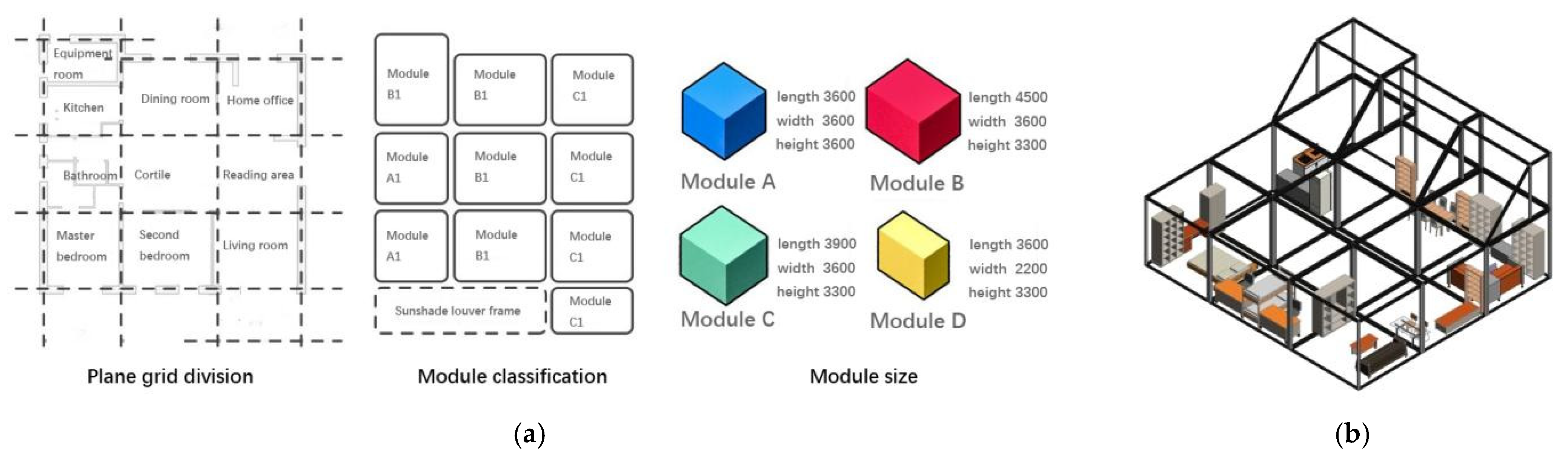
4.2.3. Collaboration Passive Design in the Stage of Functional Areas Layout Design
4.2.4. Collaboration Design Process of Passive Design in the Stage of Performance-Based Design
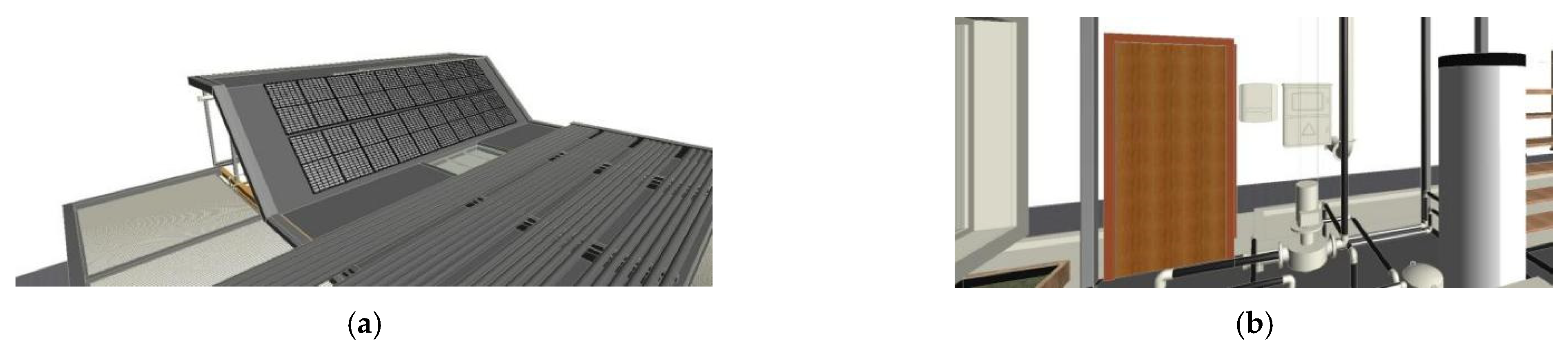
4.3. Collaborative Design of Renewable Energy Utilization
4.4. Collaboration-Oriented Active Design
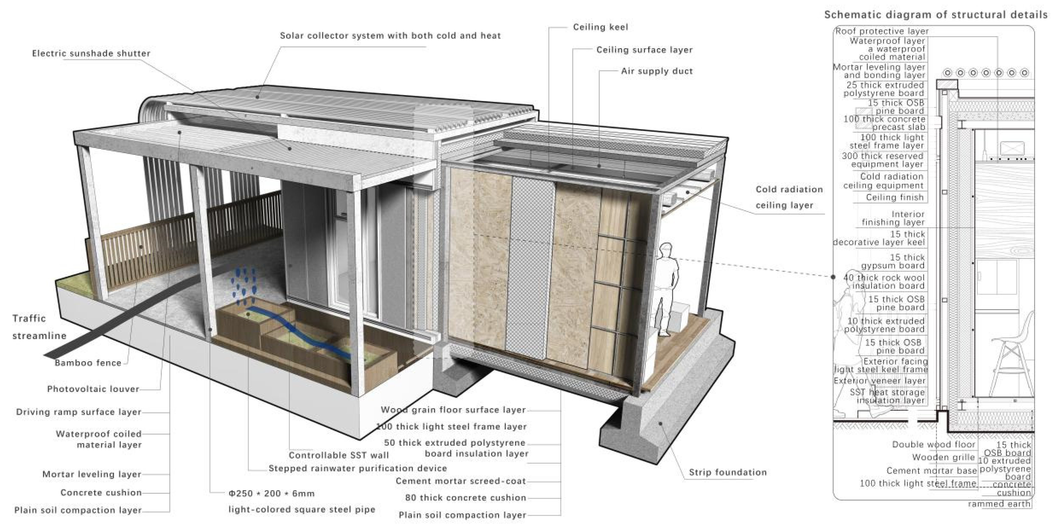
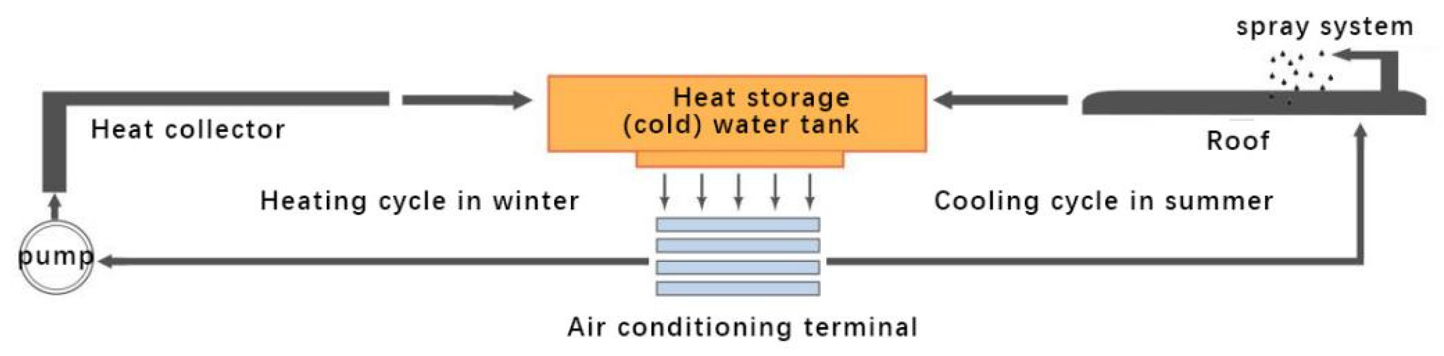
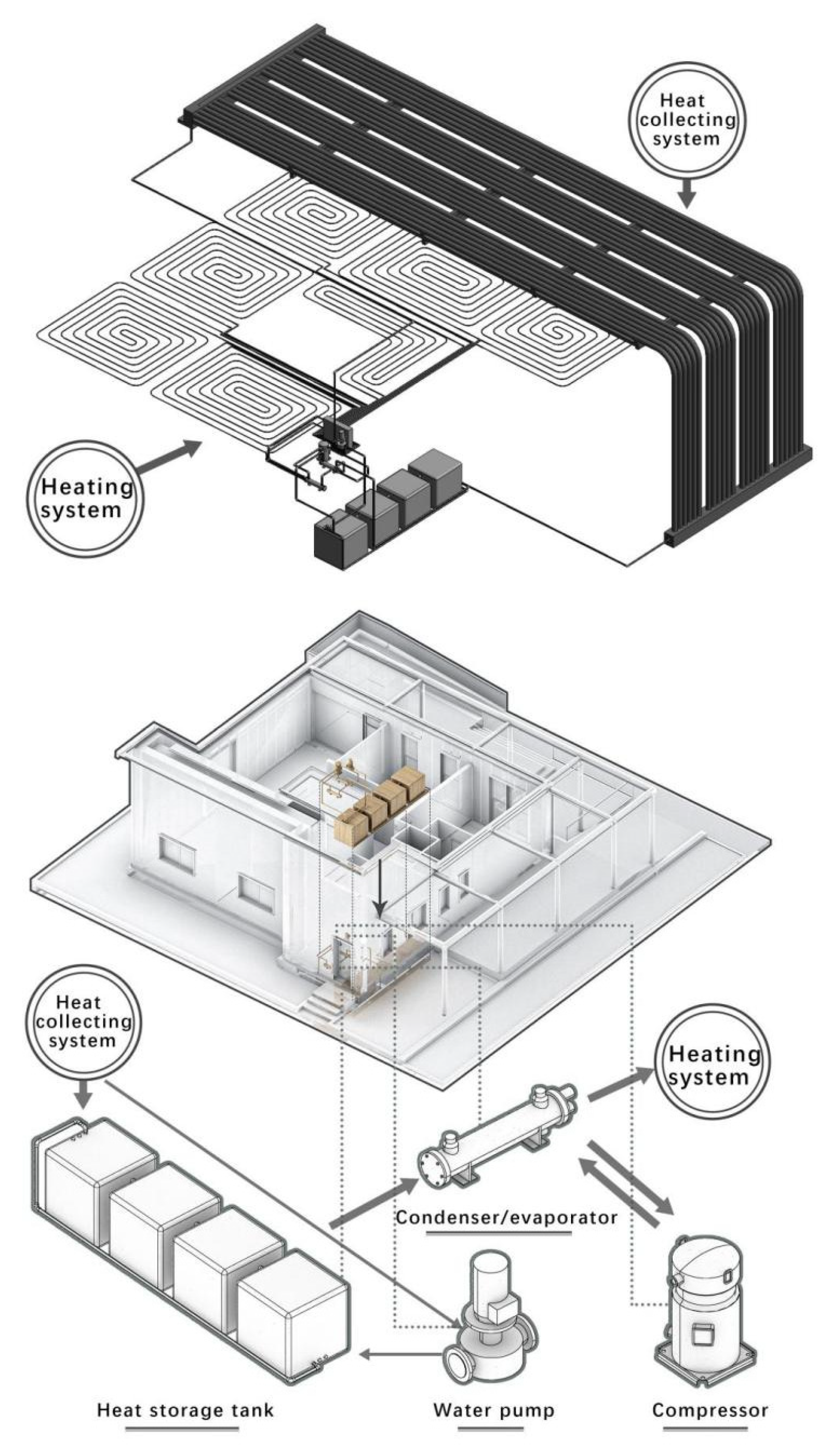
4.4.1. Collaboration in Designing Thermal System
4.4.2. Coordination in Designing HVAC System
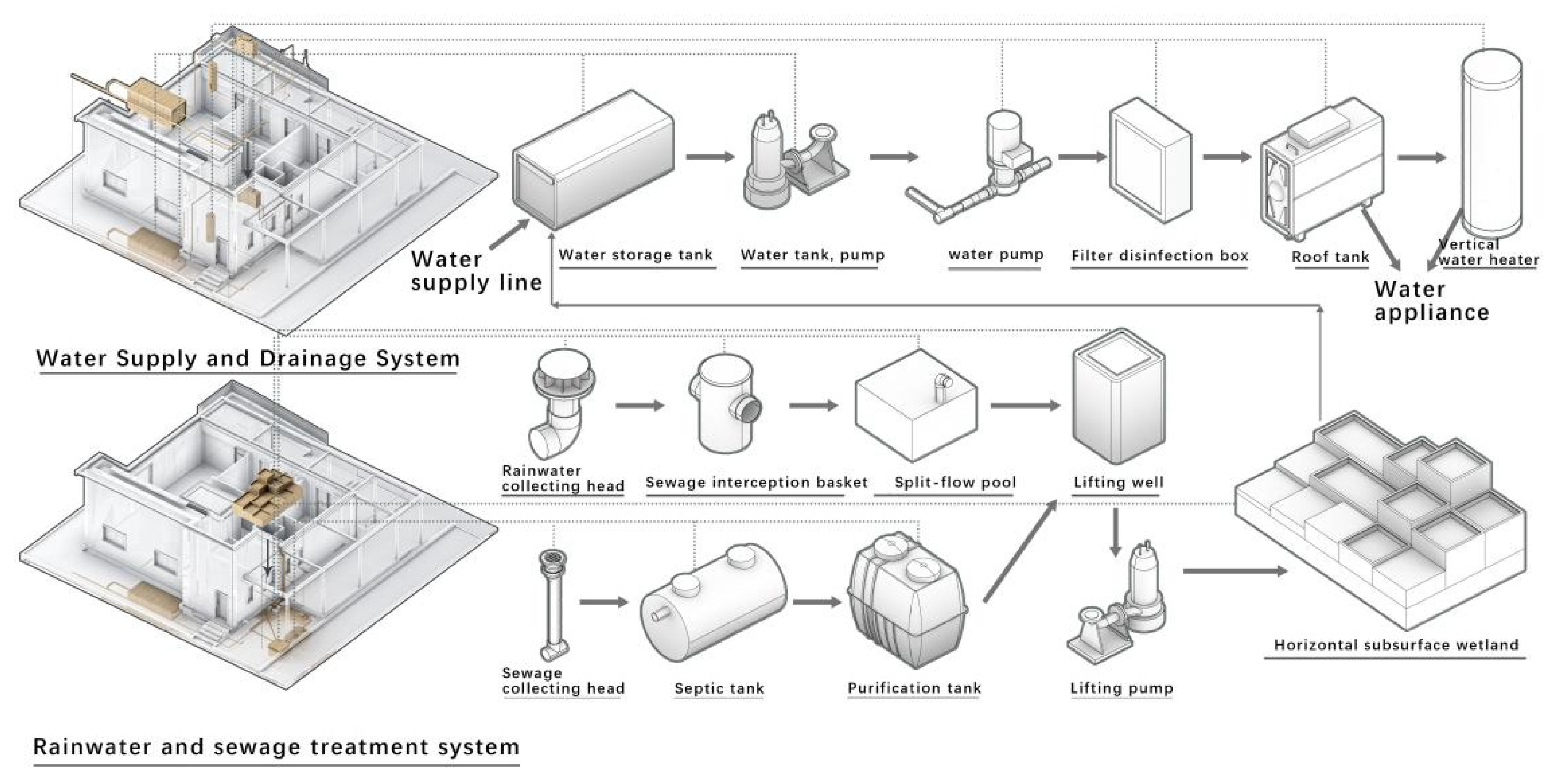
4.4.3. Coordination in Designing Water Treatment System
4.4.4. Coordination in Designing Intelligent Control System
4.5. Functions of BIM in Collaborative Design of T&A House
4.5.1. Multi-Discipline Interactive Collaborative Modeling
4.5.2. Simulation Analysis of Energy Consumption of T&A House
5. Actual Effect of the Project
6. Discussion and Conclusions
Supplementary Materials
Author Contributions
Funding
Data Availability Statement
Conflicts of Interest
Nomenclature
| T&A House | China University of Mining and Technology and Akademia Górniczo-Hutnicza House |
| SDC | Solar Decathlon China |
| BIM | Building Information Modeling |
| SST wall | Selective sun tunnel wall |
| LOD | Level of detail |
| HVAC | Heating, Ventilation and Air Conditioning |
| ZEB VMS | Zero energy building VELUX modular system |
References
- He, B.; Yang, L.; Ye, M.; Mou, B.; Zhou, Y. Overview of rural building energy efficiency in China. Energy Policy 2014, 69, 385–396. Available online: https://iopscience.iop.org/article/10.1088/1755-1315/410/1/012073 (accessed on 10 January 2022). [CrossRef]
- China Building Energy Consumption Research Report. 2020. Available online: https://www.cabee.org/site/content/24020.html (accessed on 4 January 2021).
- Rhodes, C.J. The 2015 Paris Climate Change Conference: Cop21. Sci. Prog. 2016, 99, 97–104. [Google Scholar] [CrossRef] [PubMed]
- Liu, Z.; Liu, Y.; He, B.-J.; Xu, W.; Jin, G.; Zhang, X. Application and suitability analysis of the key technologies in nearly zero energy buildings in China. Renew. Sustain. Energy Rev. 2019, 101, 329–345. [Google Scholar] [CrossRef]
- Zhang, S.-C.; Yang, X.-Y.; Xu, W.; Fu, Y.-J. Contribution of nearly-zero energy buildings standards enforcement to achieve carbon neutral in urban area by 2060. Adv. Clim. Chang. Res. 2021, 12, 734–743. [Google Scholar] [CrossRef]
- Xu, W.; Yang, X.; Zhang, S. Key Issues and Solutions for the Development of Near-Zero Energy Buildings in China. Build. Sci. 2018, 34, 165–173. [Google Scholar]
- Nearly Zero Energy Buildings Are Highly Anticipated. Available online: http://paper.people.com.cn/zgnyb/html/2022-01/10/content_25898332.htm (accessed on 10 January 2022).
- Wang, J.; Yu, C.W.; Cao, S.-J. Technology pathway of efficient and climate-friendly cooling in buildings: Towards carbon neutrality. Indoor Built Environ. 2021, 30, 1307–1311. [Google Scholar] [CrossRef]
- Zhang, Y.; Kang, J.; Jin, H. A review of green building development in China from the perspective of energy saving. Energies 2018, 11, 334. [Google Scholar] [CrossRef]
- Liu, Z.; Zhou, Q.; Tian, Z.; He, B.-J.; Jin, G. A comprehensive analysis on definitions, development, and policies of nearly zero energy buildings in China. Renew. Sustain. Energy Rev. 2019, 114, 109314. [Google Scholar] [CrossRef]
- Solar Decathlon China. Available online: https://scoring.sdchina.org.cn/ (accessed on 8 August 2022).
- Khosakitchalert, C.; Yabuki, N.; Fukuda, T. Automated modification of compound elements for accurate BIM-based quantity takeoff. Autom. Constr. 2020, 113, 103142. [Google Scholar] [CrossRef]
- Uddin, M.N.; Wei, H.H.; Chi, H.L.; Ni, M. An Inquisition of Envelope Fabric for Building Energy Performance Using Prominent BIM-BPS Tools-A Case Study in Sub-Tropical Climate. IOP Conf. Ser. Earth Environ. Sci. 2019, 354, 012129. [Google Scholar] [CrossRef]
- Bonomolo, M.; Di Lisi, S.; Leone, G. Building Information Modelling and Energy Simulation for Architecture Design. Appl. Sci. 2021, 11, 2252. [Google Scholar] [CrossRef]
- El Sayary, S.; Omar, O. Designing a BIM energy-consumption template to calculate and achieve a net-zero-energy house. Sol. Energy 2021, 216, 315–320. [Google Scholar] [CrossRef]
- Gumbarević, S.; Burcar Dunović, I.; Milovanović, B.; Gaši, M. Method for Building Information Modeling Supported Project Control of Nearly Zero-Energy Building Delivery. Energies 2020, 13, 5519. [Google Scholar] [CrossRef]
- Abouhamad, M.; Abu-Hamd, M. Life Cycle Assessment Framework for Embodied Environmental Impacts of Building Construction Systems. Sustainability 2021, 13, 461. [Google Scholar] [CrossRef]
- Singh, P.; Sadhu, A. Multicomponent Energy Assessment of Buildings using Building Information Modelin. Sustain. Cities Soc. 2019, 49, 101603. [Google Scholar] [CrossRef]
- Feng, H.; Liyanage, D.R.; Karunathilake, H.; Sadiq, R.; Hewage, K. BIM-based life cycle environmental performance assessment of single-family houses: Renovation and reconstruction strategies for aging building stock in British Columbia. J. Clean. Prod. 2019, 250, 119543. [Google Scholar] [CrossRef]
- Liu, H.; Abudayyeh, O.; Liou, W. BIM-Based Smart Facility Management: A Review of Present Research Status, Challenges, and Future Needs. In Proceedings of the Construction Research Congress 2020: Computer Applications. Construction Research Congress (CRC) on Construction Research and Innovation to Transform Society, Tempe, AZ, USA, 8–10 March 2020; Available online: https://ascelibrary.org/doi/10.1061/9780784482865.115 (accessed on 20 May 2022).
- Guo, K.; Li, Q.; Zhang, L.; Wu, X. BIM-based green building evaluation and optimization: A case study. J. Clean. Prod. 2021, 320, 128824. [Google Scholar] [CrossRef]
- Kamel, E.; Memari, A.M. Review of BIM’s application in energy simulation: Tools, issues, and solutions. Autom. Constr. 2019, 97, 164–180. [Google Scholar] [CrossRef]
- Bracht, M.K.; Melo, A.P.; Lamberts, R. A metamodel for building information modeling-building energy modeling integration in early design stage. Autom. Constr. 2021, 121, 103422. [Google Scholar] [CrossRef]
- Gao, H.; Koch, C.; Wu, Y. Building information modelling based building energy modelling: A review. Appl. Energy 2019, 238, 320–343. [Google Scholar] [CrossRef]
- Jassawalla, A.R.; Sashittal, H.C. An examination of collaboration in high-technology new product development processes. J. Prod. Innov. Manag. 1998, 15, 237–254. [Google Scholar] [CrossRef]
- Cao, D.; Li, H.; Wang, G.; Huang, T. Identifying and contextualising the motivations for BIM implementation in construction projects: An empirical study in China. Int. J. Proj. Manag. 2016, 35, 658–669. [Google Scholar] [CrossRef]
- He, Q.; Wang, G.; Luo, L.; Shi, Q.; Xie, J.; Meng, X. Mapping the managerial areas of Building Information Modeling (BIM) using scientometric analysis. Int. J. Proj. Manag. 2016, 35, 670–685. [Google Scholar] [CrossRef]
- Chen, S.Y. Use of Green Building Information Modeling in the Assessment of Net Zero Energy Building Design. J. Environ. Eng. Landsc. Manag. 2019, 27, 174–186. [Google Scholar] [CrossRef]
- Wu, K.; Tang, S. BIM-Assisted Workflow Enhancement for Architecture Preliminary Design. Buildings 2022, 12, 601. [Google Scholar] [CrossRef]
- Grilo, A.; Jardim-Goncalves, R. Value proposition on interoperability of BIM and collaborative working environments. Autom. Constr. 2010, 19, 522–530. [Google Scholar] [CrossRef]
- Ozturk, G.B. The Relationship Between BIM Implementation and Individual Level Collaboration in Construction Projects. IOP Conf. Ser. Mater. Sci. Eng. 2019, 471, 022042. [Google Scholar] [CrossRef]
- Lin, Y.-C.; Yang, H.-H. A Framework for Collaboration Management of BIM Model Creation in Architectural Projects. J. Asian Arch. Build. Eng. 2018, 17, 39–46. [Google Scholar] [CrossRef]
- Azhar, S. Building Information Modeling (BIM): Trends, Benefits, Risks, and Challenges for the AEC Industry. Leadersh. Manag. Eng. 2011, 11, 241–252. [Google Scholar] [CrossRef]
- Bryde, D.; Broquetas, M.; Volm, J.M. The project benefits of Building Information Modelling (BIM). Int. J. Proj. Manag. 2014, 31, 971–980. [Google Scholar] [CrossRef]
- Gavali, H.R.; Ralegaonkar, R.V. Application of Information Modelling for Sustainable Urban-Poor Housing. In Proceedings of the Institution of Civil Engineers-Engineering Sustainability; Ice Publishinginst Civil Engineers: Westminister, England, 2018; pp. 1–29. [Google Scholar] [CrossRef]
- Oraee, M.; Hosseini, M.R.; Edwards, D.J.; Li, H.; Papadonikolaki, E.; Cao, D. Collaboration barriers in BIM-based construction networks: A conceptual model. Int. J. Proj. Manag. 2019, 37, 839–854. [Google Scholar] [CrossRef]
- Nikas, A.; Poulymenakou, A.; Kriaris, P. Investigating antecedents and drivers affecting the adoption of collaboration technologies in the construction industry. Autom. Constr. 2007, 16, 632–641. [Google Scholar] [CrossRef]
- Zhao, X. Modelling risk paths for BIM adoption in Singapore. Life-Cycle Analysis and Assessment in Civil Engineering: Towards an Integrated Vision. In Proceedings of the 6th International Symposium on Life-Cycle Civil Engineering (IALCCE), Ghent, Belgium, 28–31 October 2018; Available online: https://acquire.cqu.edu.au/articles/conference_contribution/Modelling_risk_paths_for_BIM_adoption_in_Singapore/13447877 (accessed on 10 January 2022).
- Eadie, R.; Browne, M.; Odeyinka, H.; Mckeown, C.; Mcniff, S. BIM implementation throughout the UK construction project lifecycle: An analysis. Autom. Constr. 2013, 36, 145–151. [Google Scholar] [CrossRef]
- Andriamamonjy, A.; Saelens, D.; Klein, R. A combined scientometric and conventional literature review to grasp the entire BIM knowledge and its integration with energy simulation. J. Build. Eng. 2018, 22, 513–527. [Google Scholar] [CrossRef]
- Ministry of Housing and Urban-Rural Development of China. Terms. In Technical Standard for Nearly Zero Energy Buildings, 1st ed.; Ministry of Housing and Urban-Rural Development of China; China Architecture & Building Press: Beijing, China, 2019; p. 2. Available online: https://www.mohurd.gov.cn/gongkai/fdzdgknr/tzgg/201905/20190530_240712.html (accessed on 4 June 2021).
- Ministry of Housing and Urban-Rural Development of China. Terms. In Design Standard for Energy Efficiency of Residential Buildings in Severe Cold and Cold Zones, 1st ed.; Ministry of Housing and Urban-Rural Development of China; China Architecture & Building Press: Beijing, China, 2019; p. 2. Available online: https://www.mohurd.gov.cn/gongkai/fdzdgknr/tzgg/201909/20190910_241751.html (accessed on 4 June 2021).
- Hamidi, A.; Ramavandi, B.; Sorial, G.A. Sponge City—An emerging concept in sustainable water resource management: A scientometric analysis. Resour. Environ. Sustain. 2021, 5, 100028. [Google Scholar] [CrossRef]


| Contest | Sub-contest Number | Contest Name | Available Points | Sub-Contest Name | Available Points | Contest or Sub-Contest Type |
|---|---|---|---|---|---|---|
| 1 | n/a | Architecture | 100 | n/a | n/a | Juried |
| 2 | n/a | Engineering | 100 | n/a | n/a | Juried |
| 3 | n/a | Energy | 100 | n/a | n/a | Juried |
| 4 | n/a | Communications | 100 | n/a | n/a | Juried |
| 5 | n/a | Market Potentials | 100 | n/a | n/a | Juried |
| 6 | 6-1 | Indoor Environment | 100 | Humidity | 25 | Measured | Monitored |
| 6-2 | CO2 level | 25 | Measured | Monitored | |||
| 6-3 | PM2.5 level | 25 | Measured | Monitored | |||
| 6-4 | Lighting | 25 | Measured | Task | |||
| 7 | 7-1 | Renewable Heating & Cooling | 100 | Space | 60 | Measured | Monitored |
| 7-2 | Hot water | 40 | Measured | Task | |||
| 8 | 8-1 | Home life | 100 | Refrigerator | 15 | Measured | Monitored |
| 8-2 | Freezer | 15 | Measured | Monitored | |||
| 8-3 | Clothes Washer | 20 | Measured | Task | |||
| 8-4 | Clothes Drying | 20 | Measured | Task | |||
| 8-5 | Dinner Party | 20 | Measured | Task | |||
| 8-6 | Movie Night | 10 | Measured | Task | |||
| 9 | 9-1 | Interactive Experience | 100 | Media | 25 | Measured | Task |
| 9-2 | Theme Activity | 25 | Measured | Task | |||
| 9-3 | Into SDC House | 25 | Measured | Task | |||
| 9-4 | Into SDC Community | 25 | Measured | Task | |||
| 10 | 10-1 | Energy Self-sufficiency | 100 | Net-Zero | 50 | Measured | Monitored |
| 10-2 | Off-grid | 50 | Measured | Monitored |
| Leading Discipline | Collaborative Content | Collaborative Detail | Disciplines in Collaboration | Zero Energy Consumption Target |
|---|---|---|---|---|
| Architecture | Site environment design | Site planning, device pre-placed location, landscape design, base design | Environmental engineering, Structure | Reasonable layout of site improve the quality of the microclimate environment |
| Architectural orientation and shape design | Solar PV system, arrangement and installation position of heat collector | Energy & power engineering, Electricity | Improving the electricity produtivity by using renewable energy, and integrated design of energy use | |
| Plane layout of functional area | Arrangement of modifiable modules, division of modules | Indoor structure | Energy-saving-oriented layout, improved living comfort, modular design that facilitating construction | |
| Performance based design | Performance, air tightness and window/wall ratio of envelope structure | Structure | Reducing heat load per unit area, reducing energy consumption and exhibiting local geographical features |
| Natural Lighting Simulation Analysis | ||||||
|---|---|---|---|---|---|---|
| Window form |  |  |  |  |  |  |
| Window | Atrium | Sunroom | South-facing windows | West-facing windows | North-facing windows | East-facing windows |
| Wall ratio | - | - | 0.32 | 0.06 | 0.04 | 0.07 |
| Lighting simulation | 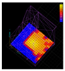 | 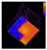 |  | 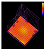 |  | 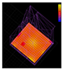 |
| Conclusion | The 1.8 × 3 m atrium brings plenty of light for public areas. | The 2.4 × 3.9 m sunroom facing the south provides extra lighting for public areas. | South-facing windows are larger to meet daily lighting requirements. | West-facing windows meet the lighting needs of auxiliary space. | North-facing windows serve the function of ventilation rather than lighting. | East-facing windows contribute little to lighting. |
| Natural Ventilation Simulation Analysis | ||||
|---|---|---|---|---|
| Opening south-facing windows | Opening north-facing windows | Opening west-facing windows | Opening east-facing windows | |
| Southeast wind |  | 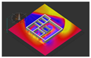 | 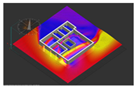 |  |
| Northwest wind |  | 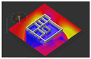 | 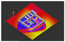 |  |
| Conclusion | When south/north-facing windows are open, the southeast wind will flow through the rooms from the north to the south and gain stack effect for indoor ventilation. | West-facing windows meet the ventilation requiremeents of the auxiliary areas in the west part of the house and do not disturb the convection in the east. | After opening east-facing windows, convection in the east part of the house is disturbed, so these windows only serve the function of lighting but not for ventilation. | |
| Disciplines in Collaboration | Field of Collaboration | Collaborative Detail | Disciplines in Collaboration | Net Zero Energy Target |
|---|---|---|---|---|
| Energy and Power | Radiator system | Roof form and installation method | Architectural design Structural design | Using solar energy resources to improve electricity productivity |
| Central control system | - | - | - | |
| HVAC system | Roof form and installation method | Interior design Structural design | Reduce energy consumption | |
| Environmental engineering | Water treatment system | Photovoltaic panel cleaning, rainwater/sewage treatment system, water supply/drainage system | Interior design Electrical engineering Energy and Power | Reduce emissions and energy consumption |
| Electrical engineering | Intelligent control system | Sewage treatment system, heat collector system, space division and layout | Interior Environmental engineering Energy and Power | Improve comfort and intelligence of the house |
| Item | Specifications |
|---|---|
| Name | Evacuated tube solar collectors |
| Thermal conductivity | Ethylene glycol |
| Number of collectors | 30 |
| Height of vertical tubes | 4 m |
| Insulation material | Glass wool |
| Outer glass tube | Grade B borosilicate glass |
| Absorption coating | Si-Ti-NO/Cu |
| Diameter of the collector | 58 mm |
| Vacuum degree | ≤5 × 10⁻⁴ Pa |
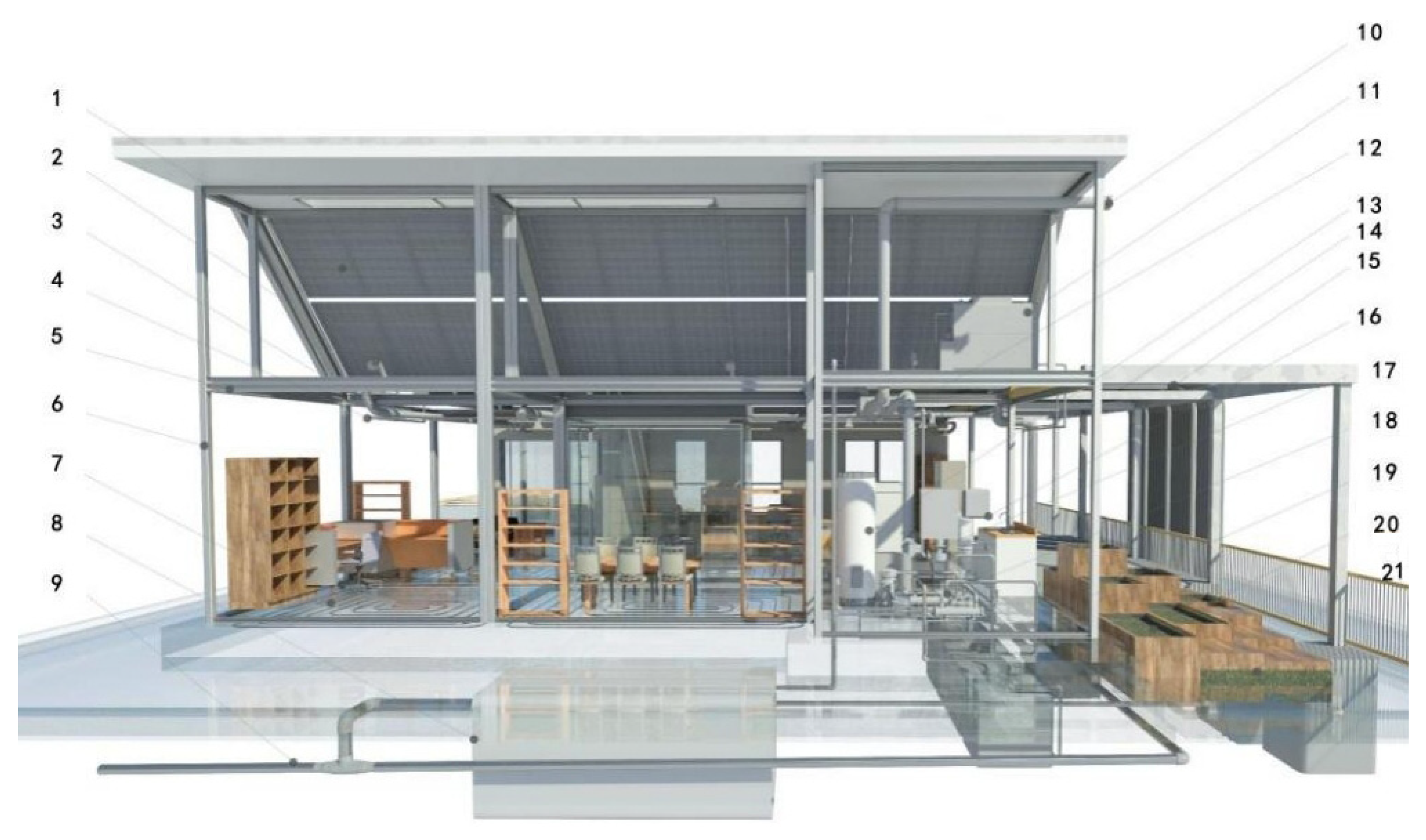
| Collaborative Modeling Content | ||||
|---|---|---|---|---|
| Discipline in collaboration | Modeling system | Number | Detail | Installation position |
| Structure | Modular framework system | 5 | 100 mm × 100 mm H beam | Setting on the strip foundation used for transferring roof load |
| 6 | 100 mm × 100 mm H steel tube | Pulling the stable frame and supporting building | ||
| Electricity | PV system | 1 | PV panels | 100 mm from the roof with the same angle as an integrated part. |
| 14 | Film photovolataic | On the top of the west veranda | ||
| 16 | Inverter and distribution box | On top of the wall of equipment room at the northwest corner. | ||
| Energy and power engineering | Thermal system | 15 | Tubular heat collector for cooling and heating | Horizontally on the roof in the east-west direction. |
| 18 | Compressor, condensing evaporator | In the equipment room at the northwest corner. | ||
| 19 | 4×1 cubic parallel water tank | Underground of equipment room. | ||
| HVAC system | 2 | Air supply pipe of fresh air system | In the interlayer of the ceiling | |
| 3 | Fresh air system lintel | Between pipe and frame where they contact | ||
| 7 | Loop type floor heating pipe | Above the frame beam and below the floor layer | ||
| 10 | Fresh air inlet | On top of the west wall of equipment room | ||
| 12 | fresh air system machine | In the ceiling of the kitchen (for easy maintenance) | ||
| 17 | Fresh air outlet | Lower half of the north wall of equipment room | ||
| Collector system | 4 | Water pipe of heat collector | In the interlayer of the ceiling (to reduce heat loss) | |
| 8 | Water storage tank | Under the north lawn (to keep warm and stay freeze-proof) | ||
| Environmental engineering | Rainwater treatment and water supply and drainage system | 9 | Municipal water supply pipe | Under the ground |
| 11 | Roof water tank | In the equipment room and above the kitchen roof | ||
| 13 | Heat exchange water tank | In the equipment room at the northwest corner | ||
| 20 | Horizontal subsurface wetland | At the green land in the northwest of the house | ||
| 21 | Purification tank & lifting well | Under the green land in the northwest of the house | ||
| T&A House | Total Energy Consumption (kWh) | Unit Area Consumption (kWh/m2) |
|---|---|---|
| Heating energy consumption | 1573.49 | 12.56 |
| Cooling energy consumption | 2399.98 | 19.16 |
| Domestic hot water energy consumption | 739.28 | 5.90 |
| Lighting system energy consumption | 1833.64 | 14.64 |
| Equipment system energy consumption | 2124.30 | 16.96 |
Publisher’s Note: MDPI stays neutral with regard to jurisdictional claims in published maps and institutional affiliations. |
© 2022 by the authors. Licensee MDPI, Basel, Switzerland. This article is an open access article distributed under the terms and conditions of the Creative Commons Attribution (CC BY) license (https://creativecommons.org/licenses/by/4.0/).
Share and Cite
Yao, G.; Chen, Y.; Xie, W.; Chen, N.; Rui, Y.; Luo, P. Research on Collaborative Design of Performance-Refined Zero Energy Building: A Case Study. Energies 2022, 15, 7185. https://doi.org/10.3390/en15197185
Yao G, Chen Y, Xie W, Chen N, Rui Y, Luo P. Research on Collaborative Design of Performance-Refined Zero Energy Building: A Case Study. Energies. 2022; 15(19):7185. https://doi.org/10.3390/en15197185
Chicago/Turabian StyleYao, Gang, Yuan Chen, Wenchi Xie, Nan Chen, Yue Rui, and Pingjia Luo. 2022. "Research on Collaborative Design of Performance-Refined Zero Energy Building: A Case Study" Energies 15, no. 19: 7185. https://doi.org/10.3390/en15197185
APA StyleYao, G., Chen, Y., Xie, W., Chen, N., Rui, Y., & Luo, P. (2022). Research on Collaborative Design of Performance-Refined Zero Energy Building: A Case Study. Energies, 15(19), 7185. https://doi.org/10.3390/en15197185