Abstract
During the oil shale drilling in Group Q of Block GL, the shale is prone to hydration, deterioration, sidewall exfoliation and frequent collapse, which affects the efficient exploration and development of shale oil. In order to reveal the mechanism of wellbore instability in the shale formation, the tectonic characteristics of shale are studied by combining microscopic and macroscopic methods, which identifies three key factors of physics, chemistry and mechanics about wellbore instability. Based on the analysis of earth stress and rock mechanics parameters, the experiment has established the prediction model of “fluid-solid-chemical coupling” collapse pressure of shale formation in Group Q, and calculated the safe drilling fluid density window for the horizontal wells of shale oil in Block GL by the prediction model. The main factors of wellbore instability in shale formation, deterioration characteristics and high density of oil-based drilling fluid on the well site is combined. The targeted plugging anti-sloughing and strong wetting agent were developed by using laser particle size instruments and pressure transmission experiments. A high thixotropy and strong plugging oil-based drilling fluid system is formed. The research results have been successfully applied in 16 horizontal wells of the shale oil test platform. The excellent rheological property, reliable plugging and bearing capacity and outstanding wellbore stabilization effect provides technical support for high-quality and efficient exploration and development of shale oil in Block GL. The “fluid-solid-chemical coupling” wellbore stabilization technology of continental shale oil formed in this study can provide a reference for the exploration and development of similar types of shale oil and gas reservoirs.
1. Introduction
In 2020, the shale in Group Q of Block GL achieved a breakthrough in oil production, and became an important strategic replacement resource of the oilfield [1]. During the drilling of several horizontal wells, taking well GYYP1 as an example, prominent problems such as the wellbore spalling and collapsing, the sidetracking of the abandoned wellbore, the loss of the reconstruction length during fracturing, workover for the casing change in the problematic stratum during production, and the instability wellbore. The concrete manifestation is that the thin shale is easily hydrated and exfoliated along the stratification crack. When the drilling fluid density is low, it is not enough to support the wellbore and when the drilling fluid density is high, it is easy to leak back and induce the wellbore instability, which seriously restricts the shale oil exploration and development process in Block GL. Compared with shale mainly deposited in marine or saline lake basins, oil shale of in Block GL has better oil generation quality [1,2,3,4,5], a higher proportion of shale thickness of foliation type and striation type [6,7]. The oil shale in Block GL has undeveloped structural fractures but highly developed horizontal foliation fractures, and has higher clay mineral content and a high degree of evolution [2]. These differences in rock fabric characteristics [8] make the wellbore instability mechanism [4] and mechanical properties [2,4] in the drilling process quite different from shale oil in other blocks, and the related theories and conventional technologies on wellbore stability cannot be directly applied [1,2,3,4,5,6,7]. Therefore, it is essential to study the mechanism and methods of wellbore instability in continental shale formation in Block GL to provide theoretical support for drilling fluid system construction, drilling design optimization and drilling technology matching.
To solve the problem of wellbore instability in shale formation, this paper presents the idea of “fluid-solid-chemical coupling” technology, which combines the study of wellbore stability mechanics with respect to drilling fluid chemistry, and carry out the analysis of formation mechanics-chemical coupling. In fact, mechanics-chemical coupling is the interaction of fluid, solid and chemical effects. Therefore, at first, it is necessary to make clear the key factors which cause wellbore instability in shale formation in Block GL, and provide the theoretical and experimental basis for the establishment of “fluid-solid-chemical coupling” model. Then, the accurately calculation of the collapse pressure changes caused by factors such as hydration of drilling fluid by the model needs to be undertaken so as to further guide the optimizing of drilling fluid, improve the drilling fluid system, and achieve wellbore stability in shale formation.
2. Causes of Wellbore Instability
Through the analysis of shale fabric characteristics, the key influencing factors of shale wellbore instability in Block GL are identified, which mainly include the following three aspects:
(1) Physical factors. Shale in Block GL is deposited in the quiet condition of the water environment, with a mudstone thickness ratio of more than 95%, and the thickness of the single layer is less than 0.2 m with the sheet structure [9]. The mudstone is mixed with thin siltstone, crust limestone and dolomite striations with poor porosity and oil content. Influenced by the overpressure of organic hydrocarbon generation and tectonic stress release, horizontal stratification fractures are extremely developed [10] with the density of 1000~3000 fractures/m (shown in Figure 1). The main types of pores are organic pores and intergranular pores of clay minerals [1,5,8], and the pore sizes are between 10 and 30 nm, with a total porosity of 6–9%. The overburden horizontal permeability is less than 0.02 mD, and the vertical permeability is one to two orders of magnitude lower than the horizontal permeability. When drilling the horizontal wells, the weak horizontal stratification section formed by the extremely developed fracture-pore nanostructures provides a channel for drilling fluid intrusion [11,12]. If the solid particles in the drilling fluid cannot effectively block the micro-fractures, it will lead to the rapid hydration and deterioration of the shale, which will aggravate the probability of wellbore instability [13].
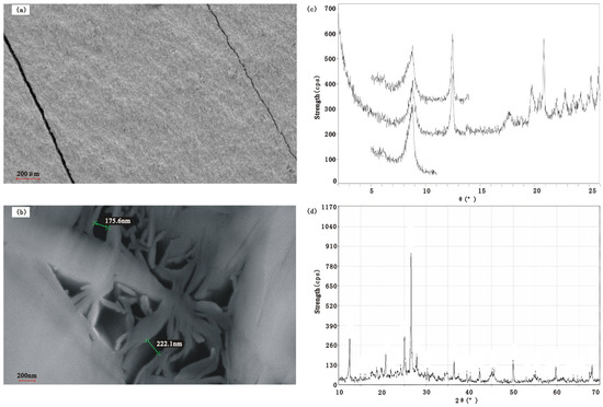
Figure 1.
Geological characteristics analysis of shale in Block GL. (a) Scanning electron microscope picture for the crack of the shale laminated structure; (b) Scanning electron microscope picture for the intergranular void of clay; (c) Map for drill core by X-ray diffractometry of the clay; (d) Map for whole rock by X-ray diffractometry of the clay.
(2) Chemical factors. The shale formation in Block GL has a high content of clay, with an average of 35.6%. It has a high degree of clay mineral evolution, which mainly consists of illite, accounting for more than 70% of clay minerals, and the silica is precipitated during transformation [1]. XRD analysis of mineral composition characteristics [14] shows high brittle mineral content, which is over 42%. Brittle mineral mainly consists of quartz with the average content of 32.5%, and the brittleness index of elastic parameter method is 33–42%. The bearing capacity of the formation is weak, and the compressive strength of rock is 28 MPa–101 MPa and it easily form cracks, a potential factors of wellbore instability. The shale is rich in organic matter, and the type of organic matter is mainly type I, with high total organic carbon, of which the content is 1.4–4.5% (TOC) [5,15,16]. The TOC in Q1 stratum is 1.8–4.5%, and the TOC in Q2 stratum is 1.4–2.2%. The maturity (Ro) is more than 1.2%, and the free hydrocarbon content (S1) is more than 8 mg/g. The gas ratio is more than 50%, and the oil saturation is more than 60%. The crude oil density is less than 0.8 g/cm3, and the viscosity is less than 10 cp. When the contact angle is greater than 145, the wettability is oil-wet, and the invasion of water-based drilling fluid easily hydrates the surface, which causes interlayer microcracks to open, expand and extend, and leads to the reduction of rock strength. The invasion of oil-based drilling fluid dissolves the light components in organic matter, changes the chemical characteristics of the rock surface, reduces the cohesion of rock, promotes the release of rock stress and destroys the stability of wellbore.
(3) Mechanical factors. The shale formation is over-pressured with the pressure coefficient greater than 1.4, and the underground physical property is better than that of the ground, which indicates that the stress release will destroy the seepage capacity of the reservoir, so the pressure coefficient of drilling fluid should be greater than that of the formation. This block is rich in illite, which is arranged along the stratification orientation, and its hydration is mainly controlled by the hydration force, which is equivalent to the repulsion force. The K+ in the interlayer can absorb up to 20 water molecules, and the generating expansion and disintegration structure may destroy the crystal layer, which belongs to the expansion type with high stress and little strain [17]. With the influence of mineral fabric, the weak surface of shale laminated structure, and under the action of pressure difference [18] and chemical potential difference [19] during drilling, the drilling fluid filtrate quickly intrudes into the stratum along the developed micro-cracks and pores. This phenomenon changes the pore pressure near the wellbore and the stress state of the rock [20]. It also causes the partial hydration of shale, the uneven distribution of hydration swelling pressure [21,22], and mechanical damage [23]. It leads to the significant reduction of shale cohesion and internal friction angle and weakening of the rock strength [24].
3. The Safe Density Window of Drilling Fluid
During the drilling process, the collapse pressure and fracture pressure will change with the influence of hydration of the drilling fluid, the angle of inclination, the azimuth angle and many other conditions [11,13,24,25], so the safe density window of the drilling fluid should be accurately calculated under various factors, which makes the drilling fluid produce enough support for the wellbore and realize the wellbore stability.
3.1. A Prediction Model of Collapse Pressure
3.1.1. Analysis of In-Situ Stress in the Block
Using twelve lengths of drill cores from Q1, Q2 and Q3 stratums from three wells, including Well G693-66-S68 in the laboratory to carry out the paleomagnetic directional experiment combined with differential strain analysis, the magnitude and direction of in situ stress in Group Q are obtained. By using the Kaiser effect measurement method of acoustic emission [10], the drill cores of three wells including Well GX7091 in Q1 and Q2 and Q3 stratums are processed for a compression test, and the acoustic emission signals are received. The stress value at the time of increasing acoustic emission activity is the maximum stress on the rock sample, and the results are shown in Table 1. According to the paleomagnetic directional experiment combined with differential strain and acoustic emission measurement experimental results, the maximum horizontal geostress gradient of Group Q of Block GL is 0.020 MPa/m, the minimum horizontal geostress gradient is 0.017 MPa/m and the vertical principal stress gradient is 0.025 mpa/m. The maximum horizontal geostress direction in Group Q of Block GL is between N100 ± 10° (shown in Table 1).

Table 1.
Experimental results of earth stress in Block GL.
3.1.2. Rock Mechanics Parameter Section
In order to establish the prediction model of “three pressures” in Group Q, that is, formation pressure, collapse pressure and fracture pressure, triaxial pressure tests with different drill core development, different confining pressure conditions and different loading directions are carried out to obtain the stress-strain curve of the core, and the elastic modulus, Poisson’s ratio and strength of the drill core are calculated. According to the Mohr-Coulomb criterion, the molar envelope circle of stratum rocks is drawn, and the internal friction angle and cohesion of shale are obtained, which is shown in Table 2. The cohesion and internal friction angle under the direction of vertical foliation is the maximum, and the cohesion under the direction of foliation of 60° is the minimum. Using the prediction model for the time difference of P-wave and S-wave, density, natural gamma and other well logging data of well GY2HC [26], the section of rock mechanics parameters is obtained, and the mechanical parameters including the elastic modulus and compressive strength of rock are obtained by laboratory triaxial compression experiment. The section of rock mechanics parameters is calibrated, and the empirical coefficient in the prediction model is obtained, and the longitudinal distribution section of rock mechanics parameters in this block is established, as shown in Figure 2.
Table 2.
Test of rock mechanical property parameters of dry shale samples in Block GL.
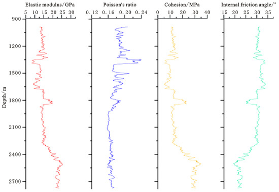
Figure 2.
Rock mechanics parameter profile of Well GY2HC.
3.1.3. A “Fluid-Solid-Chemical” Coupling Collapse Pressure Prediction Model
Multi-field coupling is widely used in the drilling engineering field, as well as other engineering communities [27,28,29], to accurately capture the coupling effects among different physical fields. In the drilling engineering field, with the drilling bit penetrating the formation and drilling fluid being injected, it will form the complex interactions among the fluid seepage field, solid stress field and the chemical potential field in underground rock. If the mud density is too low, shear failure will occur on the wellbore wall, leading to wellbore collapse or hole shrinkage. Collapse pressure refers to the lower limit of drill fluid density to prevent wellbore collapse or hole shrinkage, and it is necessary to make the stress distribution of the strata around the wellbore clear for the calculation of collapse pressure. The special rock fabric characteristics of Block GL make it more prone to hydration and collapse than the conventional formation in the drilling process, so it is necessary to establish the corresponding characterization model. After spudding the wellbore, the hydraulic action and chemical action of drilling fluid will change the pore pressure of the formation around the well, and the essence of wellbore stability analysis is to study the physical and chemical action among the fluid seepage field, solid stress field and chemical potential field. That is, by adopting the method of fluid-solid-chemical coupling, a fluid-solid coupling model with chemical potential gradient as the chemical driving force and hydraulic pressure difference as the hydraulic driving force is comprehensively established [13,18,19,21,25,30,31,32,33]. Combined with the results of in-situ stress analysis and rock mechanics parameters, as well as clearly defining the variation rule of wellbore strength with the soaking time of the drilling fluid, we establish the prediction model of “fluid-solid-chemical” coupling collapse pressure in the shale formation of Group Q.
The finite element method in Comsol is used to calculate the coupling of multiple physical fields. Taking different well types as the analysis objects, through the relationship between water content test and rock mechanics parameters, and introducing rock mechanics parameters with different water contents, the stress model of the shaft lining is solved. On this basis, the liquid column pressure corresponding to the failure collapse of the shaft wall is analyzed by the Moore-Coulomb criterion, which is taken as the collapse pressure calculation result. The calculation result parameters under different angles of inclination and azimuth angles are extracted, and the final collapse pressure equivalent density window is obtained by interpolation with the drawing software Origin.
- (1)
- Fluid-chemical coupling model
The numerical model is adopted, and its interior is a 2 m × 2 m × 2 m angle of inclination and the well borehole wall stress model with parametric scanning of azimuth angle. The model considers the coupling of fluid-solid-solid. The external is a large area of 10 m × 10 m × 10 m, which is used for in situ stress balance to eliminate stress concentration. The model adopts finer mesh processing, in which the stress calculation model is obtained by the boundary layer and ultra-fine division for the well borehole wall at the stress concentration position and the stratum with the structural plane.
The hydraulic pressure difference and the chemical potential difference are the two main factors that cause pore pressure change [24]. The volume flow through the unit body can be obtained by transforming the Darcy formula:
In Formula (1), J is the volume flow through the unit, cm3/s; n is the cross-sectional area of the unit body, m2; K is permeability, μm2; ΔP is hydraulic pressure difference, MPa; Im is membrane efficiency, dimensionless; μ is the viscosity of the fluid, mPa·s; θ is the chemical potential, J/mol; Δx is the unit length, cm.
The distribution equation of chemical potential [22] is as follows, which can be calculated according to the concentration of inorganic salt ions:
In Formula (2), x and y are diffusion distance components of chemical potential, cm; t1 is time, s; D is the chemical potential diffusion coefficient, cm2/s.
- (2)
- Fluid-solid coupling model
The rock unit is subjected to various stresses, including the extrusion load and pore pressure from surrounding rocks, and there are various forms of the strain caused by stress. According to the source of the strain, it can be divided into the average strain of dry porous media, the volume strain caused by pore pressure and the volume strain caused by tensile stress. Combined with the effective stress theory of Biot [34], considering the average strain of dry porous media, volume strain caused by pore pressure and tensile stress, the constitutive equation of solid mechanics under fluid-solid coupling is obtained. By considering these strains, the stress distribution of the formation around the well can be accurately calculated:
In Formula (3), σij is the stress tensor, MPa; λ is lame constant of stratum, dimensionless; es is the volume of solid skeleton, m3; Pp is pore pressure, MPa; β is Biot constant, dimensionless; δij is Kronecker symbol, dimensionless; G is formation shear modulus, MPa; and εij is the strain tensor, dimensionless.
The stress balance equation with displacement component ui and pore pressure Pp under fluid-solid coupling:
In Formula (4), ui is displacement component of solid skeleton, m.
The change of water content is expressed as:
In Formula (5), ζ is the change of water content, %; Φ is porosity, %; di is the relative displacement of pore fluid of the solid skeleton, m; α is a Biot coefficient, α = 1 − β, dimensionless; es is the volume of solid skeleton, m3; Kf is the compressibility of pore fluid, 1/Pa; ΔP is hydraulic pressure difference, MPa; Δθ is the chemical potential difference, J/mol; Im is membrane efficiency, dimensionless.
In an infinite axisymmetric area, such as around the wellbore, the control equation of pore pressure is obtained by combining the fluid-solid coupling model with the fluid-solid coupling model [24]:
In Formula (6), K1 is the dispersion coefficient, which is equivalent to c in the equation of Rice-Cleary [35], dimensionless. The specific expression is:
- (3)
- The change rule model of stratum strength with the soaking time of drilling fluid.
From the mechanical point of view, wellbore collapse is caused by shear failure, which accounts for the stress on the rocks around the wellbore exceeding the strength of the rocks. Generally speaking, wellbore collapse occurs at the horizontal minimum geostress position of the wellbore wall. In the study of wellbore stability mechanics [34,36,37,38], the Mohr-Coulomb strength criterion expressed by principal stresses σ1 and σ3 is:
In Formula (8), σ1 and σ3 are the maximum and minimum principal stress around the wellbore, MPa; C is cohesion, MPa; f is the internal friction coefficient of rock, f = tanφ, dimensionless; φ is the internal friction angle, °.
When shale comes into contact with drilling fluid, driven by physical and chemical actions such as chemical potential and capillary force, the drilling fluid filtrate will invade the rock, making the rock strength gradually decrease with the increase of soaking time. When the drilling fluid filtrate reaches saturation in the rock, shale stops absorbing water, and the reduction of formation strength slows down at this time [36,37,38,39,40,41]. Based on this, the variation rule of shale formation strength changed with soaking time of drilling fluid:
In Formula (9), C(t) is the formation cohesion at time t after the wellbore is spudded in, Mpa; φ(t) is the friction angle in the formation at time t after the wellbore is spudded in, °; C0 is the formation cohesion when the wellbore is just spudded in, Mpa; φ0 is the friction angle in the formation when the wellbore is just spudded in, °; t is the time after the wellbore hole is spudded in, day; A is the fitting constant of shale cohesion, dimensionless; B is the fitting constant of shale internal friction angle, dimensionless; E is the fitting constant of parameters such as dynamic viscosity of drilling fluid, dimensionless; F is the fitting constant of physical and chemical parameters of drilling fluid, dimensionless.
- (4)
- “Fluid-solid-chemical” coupling collapse pressure model
Considering pore pressure and the chemical potential difference of drilling fluid, when the diameter of the wellbore is much smaller than the hole axis, it can be regarded as a plane strain problem, that is, the axial stress around the hole is 0 Mpa. For the surrounding rock of shale sidewall, the stress distribution around the hole is:
In Formula (10), σr is the radial stress around the well, MPa; σθ is circumferential stress, MPa; σH is the maximum horizontal geostress, MPa; σh is the minimum horizontal geostress, MPa; Pm is the drilling fluid column pressure, MPa; and θ1 is the round angle of the wellbore, °.
According to the pore pressure, the stress distribution of wall rock under the action of chemical potential difference of drilling fluid, and the influence of shale formation strength with soaking time of drilling fluid, the calculation formula of “fluid-solid-chemical” coupling collapse pressure of shale stratum of Qingshankou:
In Formula (11), f1(t) and f2(t) are the internal friction coefficients of rocks at time t after the wellbore is spudded in, dimensionless. Specific Expression:
By combining the above multi-field coupling equation with the actual wellbore trajectory, and integrating the influence rule of water content and the soaking time of drilling fluid on rock strength, the variation rule of shale collapse pressure with wellbore drilling time passing can be simulated and predicted. It can effectively predict when the wellbore wall may collapse and the severity of the wellbore wall collapse and calculate the wellbore wall collapse period.
3.2. Prediction of Three-Pressure Section
Combined with the laboratory shale strength deterioration law experiment with drilling fluid soaking time passing, the prediction results of shale wellbore wall collapse pressure changes with different wellbore trajectories, dip angles and water absorption of stratum rocks in the target formation are calculated by using the “fluid-solid-chemical” coupling collapse pressure prediction model, shown in Figure 3. From the calculation results, it can be seen that with the deterioration of shale by “water absorption”, the collapse pressure gradually increases. When the shale does not deteriorate, the collapse density changes from 1.02 g/cm3 to 1.73 g/cm3. When the water content of shale reservoir increases, the shale strength value changes, and the equivalent density of wellbore collapse pressure increases rapidly. When the water content is 10% and 15%, the equivalent density respectively increases by 0.15 g/cm3–0.22 g/cm3 and 0.31 g/cm3–0.45 g/cm3, and the risk of wellbore wall instability increases continuously. The change rule of formation collapse pressure with azimuth and angle of inclination shows that when drilling directional wells, the collapse pressure is the lowest in the direction of minimum geostress, and the risk of wellbore instability is the lowest; while the collapse pressure is the highest in the direction of horizontal maximum geostress, and the risk of wellbore instability is the highest. With the increase of angle of inclination, the collapse pressure tends to increase gradually, the collapse pressure of horizontal wells is the highest and the risk of wellbore instability is the greatest.
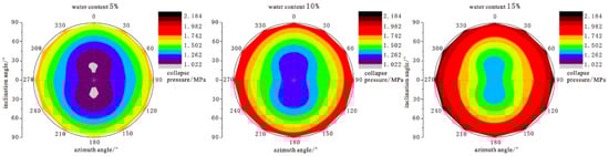
Figure 3.
Nephogram of collapse pressure distribution under different well types and water content.
Combined with the previous research results and considering the relationship between the stratification strength of stratum and soaking time, the structural section deterioration and three-pressure section correction of the stratum soaked by drilling fluid are carried out, and the correction results of collapse pressure under the actual bottom hole conditions are obtained. The safe drill fluid density windows of four wells including well GY1-Q1-H3, and two vertical wells, well GY20 and GY40 are shown in Figure 4. With the increase of soaking time, the maximum collapse pressure equivalent density respectively increases from 1.33 g/cm3 and 1.36 g/cm3 to 1.46 g/cm3 and 1.47 g/cm3, and the minimum equivalent density of fracture pressure is 1.81 g/cm3. After correction of deviation, azimuth and the deterioration of the two horizontal wells, Gy-Q1-H3 and GY2HC, the maximum equivalent density of collapse pressure respectively increases from 1.35 g/cm3 and 1.34 g/cm3 to 1.66 g/cm3 and 1.65 g/cm3, and the minimum value of fracture pressure is 1.85 g/cm3. Therefore, when the oil-based drilling fluid is used and the bottom-hole rock carrying meets the requirements, the recommended drilling fluid density for vertical wells is 1.46 g/cm3 to 1.51 g/cm3, and that for horizontal wells is from 1.66 g/cm3 to 1.71 g/cm3, which can meet the requirements of the physical support of the wellbore wall.
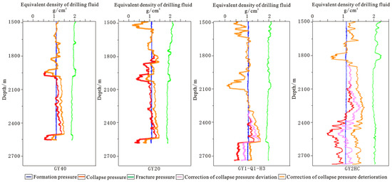
Figure 4.
Prediction of safe density window of drilling fluid.
4. Development of Drilling Fluid System
4.1. Analysis of the Characteristics of Shale Deterioration
The particularity of the continental shale lithology in Block GL determines the complexity of its interaction with the drilling fluid system. In order to clarify the deterioration characteristics of shale caused by different fluids, the drill cores of the four wells including Well GY6HC from Group Q are selected. The rolling recovery, linear expansion, acoustic test, tensile strength and triaxial compression experiments are carried out in different media such as clear water, water-based and oil-based drilling fluid. The results show that the average rolling recovery rate of shale in clean water is 96.39%, it is 98.33% in water based drilling fluid, and it is 99.52% in oil-based drilling fluid. The linear expansion rate in clear water is 2.87%, while in water-based drilling fluid it is 1.47%, and in oil-based drilling fluid it is 0.05%. Compared with oil-based drilling fluid, the time difference of shale acoustic waves in water-based drilling fluid changes more greatly, and the change range in horizontal stratification direction is smaller than that in the vertical direction. The vertical tensile strength decreases by 15% after being soaked by the oil-based drilling fluid, and decreases by 60% after being soaked by the water-based drilling fluid. When the shale is soaked in oil-based medium, its cohesion decreases by 0.6 MPa and its internal friction angle decreases by 6.1° compared with that in clean water, which indicates that its hydration cracking effect in oil-based drilling fluid is weak, its expansion rate is low, and basically no expansion occurs. When the water phase medium comes into contact with the shale, the rock strength will be weakened, which has a strong weakening effect on the shale.
Dynamic changes of mechanical parameters such as triaxial compressive strength, elastic modulus and Poisson’s ratio of rock are an important basis for judging shale hydration and deterioration. According to the Mohr-Coulomb failure criterion, a TAW2000 microcomputer-controlled triaxial stress testing machine is used indoors, and shale cores are soaked with water-based and oil-based drilling fluids to carry out the triaxial mechanical tests for soaking the shale cores for different times [2]. As shown in Table 3, with the increase of soaking time of the water-based drilling fluid, the strength of rock loaded in the horizontal stratification direction decreases rapidly. After soaking for two days, the triaxial strength decreases by 34%, resulting in foliation splitting and showing brittleness. In the vertical direction, the loading rock produces shear cracks connected with stratification cracks, and the fissure of the interlayer starts to crack, which shows a certain plasticity in general. It has little effect on the triaxial compressive strength, that is, it has little effect on shale matrix strength, and vertical loading overcomes the shear strength of the matrix. After soaking in oil-based drilling fluid for 10 days, the triaxial strength of rock decreased by 19% when loaded horizontally along the stratification direction. When loaded vertically along the stratification direction, the triaxial strength decreased by 17%, and the overall strength is high, which shows that the original anisotropy still exists [32]. After 10 days, the degree of rock deterioration gradually tends to be stable with the soaking time passing [42]. Compared with water-based drilling fluid, oil-based drilling fluid has less influence on shale rock mechanical parameters in Block GL.
Table 3.
Triaxial test results of drilling fluid soaking.
4.2. Development of High Thixotropic Plugging Oil-Based Drilling Fluid System
This block is characterized with brittle shale, a high content of clay, and mainly consists of illite. It has strong surface hydration, and developed micro-nano pores and fractures, which may easily lead to the deterioration of shale in drilling fluid. It is difficult to carry cuttings in long horizontal sections, which puts forward strict requirements for the inhibition, plugging and rheology of the drilling fluid [33].
According to the development characteristics of nano-scale pores and fractures in shale stratum, the oil-soluble formula is optimized on the basis of the original brine drilling fluid system. By using a laser particle size analyzer and a pressure transmission experiment [24,43], the lipophilic nano-polymer and micro-plugging agent FTTS, of which particle size matches the pore size of the formation, are selected as the film-forming plugging materials of the system. The particle size distribution is shown in Figure 5. According to the pressure transmission experiment, after two plugging materials are added to the oil-based drilling fluid, the pressure transmission time of the drilling fluid in the core is increased by 27.8 times and 2.9 times compared with clear water and oil-based drilling fluid. The addition of a film-forming plugging agent forms a dense polymer film on the formation surface. It improves the toughness of filter cake, effectively delays the transmission of liquid column pressure in shale, and effectively blocks nano-scale pores and joints. It also improves the chemical plugging and anti-collapse ability of the drilling fluid system.
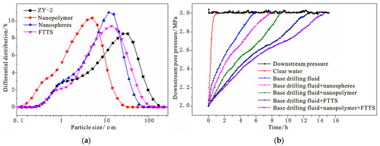
Figure 5.
Optimization test of plugging materials ((a) Particle size distribution of plugging materials; (b) Pressure transmission evaluation of oil-based drilling fluid).
In order to meet the mechanical stability effect of horizontal wells in shale stratum, the design density of drilling fluid is more than 1.65 g/cm3, and a large amount of barite powder and micro-nano materials in the system will greatly increase the viscosity and shear force of the system. At the same time, the horizontal section of shale oil horizontal wells is more than 2000 m long, and the grinding and dispersion of cuttings during long drilling periods will further increase the viscosity and shear force of the system. In order to reduce the force between solid particles, a strong polar wetting agent is added to the original system formula to reduce the interfacial tension, improve the wettability of the solid surface, improve the dispersion degree and optimize the rheology of the drilling fluid system, which is shown in Table 4. The addition of a wetting agent not only reduces the viscosity of the system, but also has no obvious influence on the shear force of the system. The addition can effectively improve the influence of weighting materials and the cuttings dispersion on the rheological properties of the drilling fluid system. It could realize the low viscosity and high shear of the high-density oil-based drilling fluid system and control the rheological properties of the drilling fluid in the operation process.
Table 4.
Effect of wetting agent on drilling fluid rheology.
Finally, a gemini quaternary ammonium salt emulsifier which can realize special phase behavior is formed, and a low viscosity and high shear water-in-oil drilling fluid system with low apparent viscosity, low plastic viscosity and reasonable dynamic shear force is formed with high efficiency organic soil. The system can resist temperatures of 150 °C, and its density can reach 1.75 g/cm3. Its demulsification voltage is more than 800 V, and high temperature and high pressure filtration loss is less than 3.0 mL.
5. Wellsite Test
Sixteen shale oil horizontal wells including well SL-Q1 on platforms in Block GL has been completed with the oil-based drilling fluid system under high thixotropy and strong plugging, which is developed in laboratory.
It is found that the cleaning problem of cuttings bed in the long horizontal section is prominent in the operation. During the spudding-in period of the completion operation for horizontal wells, the phenomenon of pressure hold-up occurred from time to time, and it is easy to hold back and leak the formation, which leads to the wellbore instability. The main reason is that the rheological property of drilling fluid is not controlled enough. When the viscosity shear is high, the flow resistance increases and the ECD increases. By further optimizing the drilling fluid performance in real time, the annular pressure loss is reduced. During the second spudding-in, it has low viscosity, low water loss, the funnel viscosity is 40–50 s, and the API water loss is less than 4 mL, which reduces the probability of cuttings sticking to the wellbore wall. During the third spudding-in, the reading of the six-speed meter is adjusted to eight at six revolutions, and it is increased to 10 before landing. The dynamic-plastic ratio is increased to 0.3 Pa/mPa·s–0.4 Pa/mPa·s so as to improve the rock-carrying effect and fully purify the wellbore. At the same time, according to the change of downhole ECD, the drilling fluid density is appropriately adjusted to ensure that the downhole ECD is less than the leakage pressure and prevent the occurrence of lost circulation.
In view of the instability caused by scraping against the wellbore during operation. According to the characteristics of shale falling, the periodic tripping is cancelled. Timely circular reaming is carried out according to the change of underground ECD, with a large displacement of 34 L/s–40 L/s and a high rotation speed of 70 rpm–80 rpm. On the premise of ensuring the stability of the wellbore, the drilling operation parameters are optimized, such as low rotation speed in the mud-making stratum and high rotation speed in the expansive stratum in the second spudding-in. Adjusting the rotation speed according to the screw angle in the third spudding-in, reducing the rotation speed in the reaming stage, and adjusting the displacement in real time according to the wellbore condition. Meanwhile, elaborate operations such as controlling the spudding-in speed, starting and stopping the pump step by step, and weighting the drilling fluid in multiple cycles are adopted to reduce the downhole pressure fluctuation and ensure a smooth and controlled operation.
Relying on the reasonable drilling fluid density design, the excellent plugging and anti-collapse ability of the system, timely and effective drilling fluid adjustments on the wellsite and a smooth operation, there are no complicated situations such as wellbore collapse and sticking during the operation process, which effectively ensured the wellbore stability and wellbore cleaning. The depths of the shale oil horizontal wells on the test platform are from 4791 to 4875 m, the vertical depths are 2452–2592 m, the horizontal lengths are 2032 to 2506 m, and the design of drilling fluid density is 1.65 to 1.73 g/cm3. During the wellsite test, the plastic viscosity and apparent viscosity of the oil-based drilling fluid are reasonable, the viscosity at six turns is high, the dynamic shear force is reasonable, the thixotropy is strong, and the cuttings return is normal. The demulsification voltage is more than 800 V, the emulsification stability is good, and there is no oil-water stratification phenomenon. There is no sticking display and wellbore wall peeling, and the tripping operation is smooth. After the well completion, there is no sticking display in drifting, well logging is smooth, and there is no sticking display during casing running. The cementing operation is normal, and the ability of stabilizing the wellbore wall is strong. The drilling and completion period is shortened from 113 days to an average of less than 30 days after the test. The successful application of sixteen test wells verifies that the “fluid-solid-chemical coupling” wellbore stabilization technology of continental shale oil can meet the requirements of safe and fast drilling of shale oil horizontal wells in Block GL.
6. Conclusions
(1) The influencing factors of wellbore instability in shale formation in Block GL are clear and definite. The average clay mineral content of shale stratum in this block is 35.6%, the average content of brittle mineral is 32.5%, the foliation density is 1000–2500 pieces/m, the TOC value is 1.4–4.5%, and the content of the organic matter is rich. Under the action of pressure difference and chemical potential difference, drilling fluid filtrate will quickly invade the stratum along the pores and fractures, and the water phase will easily cause the hydration of the illite surface, resulting in the opening, expansion and extension of interlayer micro-fractures, which result in a decrease in rock strength. The oil phase dissolves the organic matter, reduces the cohesion of the rock, and promotes the stress release of the rock. Under the comprehensive action of physical, chemical and mechanical factors, the shale oil horizontal wells frequently suffer from wellbore instability.
(2) A theoretical model of “fluid-solid-chemical” coupling collapse pressure prediction is established. Based on the well logging interpretation data and triaxial stress experiments after soaking in different fluid media, and with full consideration of hydraulic pressure difference and chemical potential difference, the prediction method of “fluid-solid-chemical” coupling collapse pressure is established, and the change rule of formation collapse pressure under different parameters such as angle of inclination, azimuth and water content is defined. The safe drilling fluid density window of shale oil horizontal wells in this block is given, and the drilling fluid density of the target interval of vertical wells is recommended to be from 1.46 g/cm3 to 1.51 g/cm3, and that of the horizontal well interval is recommended to be from 1.66 g/cm3 to 1.71 g/cm3, which can meet the requirements.
(3) A targeted oil-based drilling fluid system has been constructed. According to the main factors affecting the wellbore instability of shale formation in Block GL and the characteristics of high density of oil-based drilling fluid in wellsite operation, a targeted plugging and anti-sloughing agent and a strong polar wetting agent are selected, and a high thixotropic and strong plugging oil-based drilling fluid system is formed. The system has excellent rheological properties under high density, the plugging pressure-bearing capacity is more than 5 MPa, the demulsification voltage is more than 800 V, and the comprehensive performance is stable. The wellsite test of sixteen horizontal wells in shale oil test platforms has been successful. Relying on reasonable drilling fluid density, excellent plugging and anti-collapse ability and timely and effective drilling fluid adjustment on the wellsite, the effect of stabilizing wellbore is outstanding, which provides technical support for the efficient exploration and development of shale oil.
Author Contributions
Conceptualization, X.A.; Data curation, X.A.; Formal analysis, X.A.; Funding acquisition, X.A.; Investigation, X.A.; Project administration, X.A.; Resources, X.A.; Methodology, M.C.; Supervision, Writing—review & editing, M.C. All authors have read and agreed to the published version of the manuscript.
Funding
The Major Science and Technology Project of PetroChina Company Limited-“Research on Exploration and Development Theory and Key Technologies of Shale Oil in Daqing Gulong” (2021ZZ10).
Conflicts of Interest
The authors declare no conflict of interest.
References
- Sun, L.; Liu, H.; He, W.; He, W.; Li, G.; Zhang, S.; Zhu, R.; Jin, X.; Meng, S.; Jiang, H. Analysis of major scientific issues and research paths of Daqing Gulong shale oil. Pet. Explor. Dev. 2021, 48, 527–540. [Google Scholar] [CrossRef]
- Liu, H.; Cui, S.; Zhu, D.; Li, Y.; Zhang, L. Study on microstructure and mechanical properties of hard and brittle shale. J. Undergr. Space Eng. 2019, 15, 34–39. [Google Scholar]
- Wang, G. Hydration Characteristics of Hard and Brittle Shale and Its Influence on Wellbore Collapse Pressure; Southwest Petroleum University: Chengdu, China, 2017. [Google Scholar]
- Liu, H.; Cui, S.; Meng, Y.; Li, Z.; Yu, X.; Sun, H.; Zhou, Y.; Luo, Y. Rock Mechanics and Wellbore Stability of Deep Shale During Drilling and Completion Processes. J. Pet. Sci. Eng. 2021, 205, 108882. [Google Scholar] [CrossRef]
- He, W.; Meng, Q.; Zhang, J. Main control factors and classification evaluation of Gulong shale oil enrichment in Songliao Basin. Daqing Pet. Geol. Dev. 2021, 40, 1–12. [Google Scholar]
- Song, M.; Liu, H.; Wang, Y.; Li, Y. Understanding and exploration practice of Paleogene shale oil enrichment in Jiyang Depression. Pet. Explor. Dev. 2020, 47, 225–235. [Google Scholar] [CrossRef]
- Yao, J.; Zhao, Y.; Liu, G.; Qi, Y.; Li, Y.; Luo, A.; Zhang, X. Reservoir-forming conditions and key technologies of exploration and development in Qingcheng Oilfield. Acta Pet. Sin. 2020, 41, 777–795. [Google Scholar]
- Liu, B.; Shi, J.; Fu, X.; Lyu, Y.; Sun, X.; Gong, L.; Bai, Y. Lithofacies characteristics of continental shale rock series and shale oil enrichment conditions—A case study of organic-rich shale in one section of Qingshankou Formation of Cretaceous in Gulong Depression, Songliao Basin. Pet. Explor. Dev. 2018, 45, 828–838. [Google Scholar] [CrossRef]
- Liu, G. Petroleum Geology; Petroleum Industry Press: Beijing, China, 2018; pp. 158–162. [Google Scholar]
- Chen, Z.; Meng, Q.; Wan, T.; Jia, Q.; Zhang, T. Numerical simulation of tectonic stress field in Gulong Depression of Songliao Basin by elastic-plastic incremental method. Earth Sci. Front. 2002, 9, 483–492. [Google Scholar]
- Zhou, J.; He, S.; Tang, M.; Huang, Z.; Chen, Y.; Chi, J.; Zhu, Y.; Yuan, P. Analysis of wellbore stability considering the effects of bedding planes and anisotropic seepage during drilling horizontal wells in the laminated formation. J. Pet. Sci. Eng. 2018, 170, 507–524. [Google Scholar] [CrossRef]
- Hu, S.; Bai, B.; Tao, S.; Bian, C.; Zhang, T.; Chen, Y.; Liang, X.; Wang, L.; Zhu, R.; Jia, J.; et al. Heterogeneous geological conditions and differential enrichment characteristics of high maturity shale oil in China. Pet. Explor. Dev. 2022, 49, 224–237. [Google Scholar] [CrossRef]
- Chen, P.; Ma, T.; Xia, H. Prediction Model of Shale Horizontal Well Collapse with Multiple Weak Faces. Nat. Gas Ind. 2014, 34, 87–93. [Google Scholar]
- Wang, B.; Sun, J.; Shen, F.; Li, W.; Zhang, W. Mechanism of wellbore instability in continental shale gas horizontal sections and its water-based drilling fluid countermeasures. Nat. Gas Ind. B 2020, 7, 680–688. [Google Scholar]
- Zhang, G.; Zhang, J.; Zhao, Y.; Lv, J.; Cheng, X.; Yang, H.; Lu, G.; Ma, M. Main control factors for the enrichment of interbedded shale oil in the two section of Qingshankou Formation in Qijia area of northern Songliao Basin. Pet. Geol. Dev. 2019, 38, 143–150. [Google Scholar]
- Wang, Y.; Liang, J.; Zhang, J.; Zhao, B.; Zhao, Y.; Liu, X.; Xia, D. Resource potential and exploration direction of shale oil in Gulong of Songliao Basin. Pet. Geol. Dev. 2020, 39, 15. [Google Scholar]
- Chenevert, M.E. Shale alteration by water adsorption. J. Pet. Technol. 1970, 22, 141–148. [Google Scholar] [CrossRef]
- Van Oort, E. On the physical and chemical stability of shales. J. Pet. Eng. 2003, 38, 213–235. [Google Scholar] [CrossRef]
- Hale, A.H.; Mody, F.K.; Salisbury, D.P. Influence of chemical potential on wellbore stability. SPE Drill. Completion 1993, 8, 207–216. [Google Scholar] [CrossRef]
- Deng, F. Study on the Law of Drilling Fluid Invading Shale Formation and Its Influence on Wellbore Stability; Southwest Petroleum University: Chengdu, China, 2019. [Google Scholar]
- Chen, G.; Ewy, R.T.; Yu, M. Analytic solutions with ionic flow for a pressure transmission test on shale. J. Pet. Sci. Eng. 2010, 72, 158–165. [Google Scholar] [CrossRef]
- Oort, E.V.; Hale, A.H.; Mody, F.K.; Roy, S. Critical parameters in modeling the chemical aspects of borehole stability in shales and in designing improved water based shale drilling fluids. J. Pet. Technol. 1994, 171–186. [Google Scholar]
- Xiang, C.; Chen, J.; Yang, G. Experiment on strength characteristics of brittle shale under drilling fluid immersion. Fault Block Oil Gas Field 2018, 25, 803–806. [Google Scholar]
- Wang, J. Study on the Mechanochemical Coupling Model of Shale Wellbore Stability; China University of Petroleum: Beijing, China, 2007. [Google Scholar]
- Lu, Y.; Chen, M.; Yuan, J.; Jin, Y.; Teng, X. Instability mechanism of inclined shaft in anisotropic stratum. Acta Pet. Sin. 2013, 34, 563–568. [Google Scholar]
- Zhang, W.; He, S.; Guo, Q. Prediction method and prospect of seismic data pressure. Adv. Geophys. 2005, 20, 814–817. [Google Scholar]
- Keyes, D.E.; Mcinnes, L.C.; Woodward, C.; Gropp, W.; Myra, E.; Pernice, M.; Bell, J.; Brown, J.; Clo, A.; Connors, J.; et al. Multiphysics Simulations Challenges and opportunities. In Proceedings of the IEEE International Conference on High Performance Computing, Data, and Analytics, Bengaluru, India, 18–21 December 2013. [Google Scholar]
- Zhang, H.; Guo, J.; Lu, J.; Li, F.; Xu, Y.; Downar, T.J. An Assessment of Coupling Algorithms in HTR Simulator TINTE. Nucl. Sci. Eng. J. Am. Nucl. Soc. 2018, 190, 287–309. [Google Scholar] [CrossRef]
- Fernández, M.A.; Moubachir, M. A Newton method using exact jacobians for solving fluid–structure coupling. Comput. Struct. 2005, 83, 127–142. [Google Scholar] [CrossRef]
- Roatei, S. On the variational formulation of a chemically active shale constitutive model. Proc. Rom. Acad. Ser. A 2010, 11, 116–124. [Google Scholar]
- Sarout, J.; Detournay, E. Chemoporoelastic analysis and experimental validation of the pore pressure transmission test for reactive shales. Int. J. Rock Mech. Min. Sci. 2011, 48, 759–772. [Google Scholar] [CrossRef]
- Li, J.; Liu, G.; Chen, M. A new stress model of rock around the wellbore in orthotropic stratum. J. Rock Mech. Eng. 2011, 30, 2481–2485. [Google Scholar]
- Zhang, S.; Wang, H.; Qiu, Z.; Cao, W.; Huang, H.; Chen, Z. Calculation method of safety density window of fluid-solid-chemical coupling in shale wellbore wall. Pet. Explor. Dev. 2019, 46, 1197–1205. [Google Scholar]
- Biot, M.A. Theory of Elasticity and Consolidation for a Porous Anisotropic Solid. J. Appl. Phys. 1955, 26, 182–185. [Google Scholar] [CrossRef]
- Rice, J.R.; Cleary, M.P. Some Basic Stress Diffusion Solutions for Fluid-Saturated Elastic Porous Media with Compressible Constituents. Rev. Geophys. Space Phys. 1976, 14, 227–241. [Google Scholar] [CrossRef]
- Xiao, Z. Study and Application of Fluid-Solid-Chemical Coupling Model of Hard and Brittle Shale Wellbore Wall Stability; Yangtze University: Wuhan, China, 2020. [Google Scholar]
- Ma, T.; Zhang, Y.; Qiu, Y.; Liu, Y.; Chen, P. Risk assessment method of inclined shaft instability based on reliability theory. Acta Pet. Sin. 2021, 42, 1486–1498. [Google Scholar]
- Xiao, Z.; Jia, S.; Qi, X.; Dai, Y.; Lv, F.; Jia, L.; Wen, C. Discussion on progressive failure effect of hard and brittle shale wellbore wall under fluid-solid-chemical coupling condition. J. Cent. South Univ. Nat. Sci. Ed. 2019, 50, 2464–2480. [Google Scholar]
- Ma, T. Study on the Mechanism of Wellbore Collapse and Instability of Shale Gas Horizontal Wells; Southwest Petroleum University: Chengdu, China, 2015. [Google Scholar]
- Ding, L.; Wang, Z.; Lu, J.; Sun, Y. Stability model of inclined wellbore wall in layered strata based on Mogi-Coulomb strength criterion of surrounding rock ontology. J. Rock Mech. Eng. 2017, 36, 622–632. [Google Scholar]
- Yan, C.; Deng, J.; Wei, B.; Tan, Q.; Deng, F.; Zhu, H.; Hu, L.; Chen, Z. Study on wellbore collapse pressure of shale gas reservoir. J. Rock Mech. Eng. 2013, 32, 1595–1602. [Google Scholar]
- Guang, X.; Chen, Z.; Liu, X.; Wang, Y.; Si, N. Study on wellbore stability of rational shale formation under triaxial stress. Sci. Technol. Eng. 2015, 15, 54–57. [Google Scholar]
- Chen, J. Evaluation method of drilling fluid wellbore stability for hard and brittle shale. Oilfield Chem. 2018, 35, 151–156. [Google Scholar]
Publisher’s Note: MDPI stays neutral with regard to jurisdictional claims in published maps and institutional affiliations. |
© 2022 by the authors. Licensee MDPI, Basel, Switzerland. This article is an open access article distributed under the terms and conditions of the Creative Commons Attribution (CC BY) license (https://creativecommons.org/licenses/by/4.0/).