Abstract
In this article, a theoretical 1-D heat transfer model and conjugate heat transfer numerical simulation was carried out to evaluate the thermal insulation of TBCs under different factors. The relationship of temperature-drop between the inner or outer surface of thermal barrier coating (TBC) was investigated by conjugate heat transfer numerical simulation. The effect of TBC and the coupling between the internal and external heat transfer are obtained, which indicates that TBC and film cooling can both contribute to an overall cooling performance. In addition, the combination of the two results are better results than the two alone. However, the two weaken each other’s contribution to the overall cooling performance. Meanwhile, unlike the effect of film cooling, the change in the internal heat transfer coefficient basically does not affect the thermal insulation effect of coatings. Furthermore, sensitive analysis on the different levels of film cooling and coating’s thermal insulation was conducted to the overall cooling effectiveness, with the blowing ratio ranging from 0.25 to 0.5, thermal resistance ratio ranging from 3 to 9, and the internal heat transfer coefficient ranging from 5000 W/(m2∙K) to 15,000 W/(m2∙K). The results reveal that near the exit of the film hole, film cooling plays a major role in the overall cooling effectiveness. However, with the increase in dimensionless distance, the contribution of coatings and the internal heat transfer coefficient to overall cooling effectiveness gradually increases, especially the contribution of coatings.
1. Introduction
To obtain a higher power output, the turbine inlet temperature (TIT) has been rapidly increasing over the past decades [1], which causes unbearable working conditions for the turbine blade. To date, the TIT is more than 2000 K, which is far beyond the allowable temperature of the current materials of turbine airfoils [1].
Thus, the development of turbine cooling techniques and the improvement of materials are key factors for the safety of aero-engines [2]. In the past decades, with technological progress, the TIT has increased significantly, among which, 30% comes from the progress of materials and processing technology, and 70% comes from advanced cooling technology and thermal barrier coating (TBC). Hence, it is significant to master the combined effects of TBC and cooling technology [3,4,5].
TBCs are used widely in turbine blades due to the superior thermal insulation performance of ceramic materials [6]. In 1953, NASA put forward a protective system for coating high temperature-resistant and high thermal-insulated ceramics on the surface of superalloys. It was reported that TBCs with a thickness of 250 µm can reduce metal substrate by 110~170 °C, which is equal to the sum of the development of superalloys in the past 30 years to improve the thermal-bearing capacity [7]. Thus, TBCs have been receiving wide attention in recent years.
The US Pratt & Whitney company Meier SM (East Hartford, CT, USA), Gupta D K [8] systematically conducted the successful ground engine test of the first turbine blade of PW2000, and obtained a ceramic thermal efficiency under EB-PVD spraying. An experimental evaluation of thermal benefits of TBCs that focused on the metal substrate temperature of ceramic and non-ceramic coated blades, displayed that blades with a 5 mil coating had an operating temperature-drop of up to 139 °C in hot spots compared to uncoated blades. Davidson, F.T., Dees, J.E. et al. [9] investigated the interaction between TBCs and various film cooling configurations with the thickness and thermal conductivity of TBCs in the coupled heat transfer model being matched with the thickness and heat of the engine. The result revealed that adding TBCs to the blade surface can increase the blade surfaces’ overall cooling effectiveness downstream of the coolant hole by 0.25 compared to the one without film cooling. Additionally, due to the change in blowing ratio, TBCs significantly inhibited the change in overall cooling effectiveness by reducing the adverse effects of coolant jet separation. Padture et al. pointed out, when accepted by Science in 2002, that the application of 100–400 μm thick thermal barrier coatings (TBCs) can reduce the metal temperature by 100–300 °C [10].
However, in recent years, studies have shown that there is a large gap between the expectation of TBCs’ thermal insulation effect with its reality. Prasert, P. et al. [11] used numerical approaches to illustrate that TBCs’ thermal insulation was far less than expected, at only approximately 30 °C. At the same time, the thermal insulation performance of TBCs in practical applications was not up to expectation. Some aero-engine-related design departments pointed out that if the situation did not worsen, the thermal-bearing capacity of blades would not increase significantly after the application of TBCs. Unfavorable cases such as the peeling of TBCs and blockage of the film-holes appeared, which were not conducive to the cooling of blades [12,13]. Ekkad, S.V., Han, J.C. et al. [14] simulated the turbine blade leading edge model of TBCs’ peeling, and gave a detailed heat transfer distribution under the coating peeling off at different positions and angles on the leading edge of the blade. Experimental measurements used to acquire detailed heat transfer characteristics by transient liquid crystal technology indicated that the location and depth of the spallation (shedding) had a great influence on the local heat transfer distribution of the front edge. Maikell et al. [15] conducted experimental studies on the film-cooling effectiveness of the leading edge of turbine blades with or without sprayed TBCs and found that under the same conditions, the metal substrate temperature was significantly reduced after the TBC was applied. However, the exterior surface temperature of the coating was higher than the one without a sprayed coating by about a few K. Hence, how to evaluate the effect of the thermal barrier coating reasonably at this time became a difficult problem.
Therefore, the current use and evaluation standards of thermal barrier coatings (TBCs) suffer the following issues:
- At present, the temperature-drop of the coating itself is used to evaluate the thermal insulation effect alone, and the temperature of the blade substrate is more concerned about the design and use of the engine, that is, the temperature-drop of the blade substrate caused by the spray coating, so the coating effect after actual application often fails to meet expectations.
- The related research on the thermal insulation mechanism of the coating is insufficient. The coating relies on its high thermal resistance, but the heat conduction of the coating is just one part of the heat transfer between the inside and outside of the blade. The influence of layer thickness, thermal conductivity, and other factors on the thermal insulation effect cannot be combined with the internal and external heat transfer of the blade.
Combining the heat conduction of the coating with external gas heat transfer, external film cooling, and internal cooling is necessary to extract the thermal insulation mechanism of the coating, and then it is necessary to find out the relevant factors that affect the thermal insulation effect of the coating. In addition, it is necessary to refine the relationship between the temperature-drop of the coating itself and the temperature-drop of the metal substrate of the blade, and even further find out the relationship between the temperature-drop of the coating and the increase in the turbine inlet temperature (TIT).
2. One-Dimensional Theoretical Heat Transfer Model and Mechanism Analysis of TBCs
Figure 1 shows the schematic of heat transfer through a turbine vane with and without TBC by using a one-dimensional (1-D) heat transfer analysis model. For this model, are the temperatures of hot gas and cooling gas, is the internal heat transfer coefficient, and are the external fuel gas heat transfer coefficient with or without TBC, respectively, and are the internal surface temperature of metal substrate with or without TBC, respectively, and are the external surface temperature of metal substrate with or without TBC, respectively, and represents the external surface temperature of TBC.
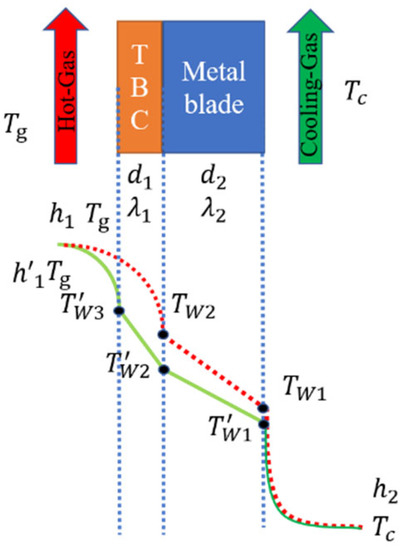
Figure 1.
1-D heat transfer model.
In addition, the temperature-drop of the coating itself and the temperature-drop difference between the external surface of the metal blade with or without coating can be defined as and in Equations (1) and (2), respectively:
Through the 1-D heat transfer model, the heat flow without or with coating can be derived, as shown as and in Equations (3) and (4):
When the working conditions of hot gas and cooling gas are kept constant, through the relationship between heat flow and temperature, Equation (5) can be obtained:
The results show that the temperature-drop of the coating itself () is proportional to the temperature-drop difference between the external surface of the metal blade with or without coating (). Additionally, this ratio is affected by the internal and external heat transfer coefficient, and the thermal resistance of the coating and metal blade. mainly reflects the coating function, where, represents the thermal resistance of the coating, and stands for the change in the external convection heat transfer coefficient caused by the use of the coating, and the term is basically independent of the coating application.
When the coating causes the metal blade external surface temperature-drop , it is necessary to ensure the same , which means, take as , and then the relationship between metal blade external surface temperature-drop by TBC application and the increase in turbine inlet temperature can be obtained as:
Similarly, the function of the coating is reflected in its thermal resistance and the resulting external convection heat transfer coefficient . Therefore, we can obtain the relationship between the temperature-drop of the coating itself (), which is a current evaluation of the TBC effect and the temperature-drop difference between the external surface of the metal blade with or without coating (), of which aero-engines really consider. Furtherly, we can obtain the corresponding increase in turbine inlet temperature. This has a certain reference value for understanding the thermal insulation mechanism of the TBC and can help to further establish a more reasonable evaluation of the TBC effect.
3. Numerical Calculation
In order to examine the relationship between the temperature-drop of the coating itself () and the temperature-drop difference between the external surface of the metal blade with or without coating (), and to explore the heat transfer mechanism under the joint action of the coating and the internal and external heat transfer, we used ANSYS 16.0 software to make a series of numerical calculations. The coupled numerical solution can solve the fluid and solid calculation domain through different solvers, flexibly edit different calculation methods in different regions, and has great advantages in the coating insulation problem of multi-layer structures [16,17,18,19,20,21,22].
3.1. Computation Model
Figure 2 shows the calculation domain of the film-coating coupling effect model which is chosen as two-dimensional to reduce the calculation complexity. The domain consists of the gas side, TBC, and metal part, which is 33 mm long and 9.3 mm wide. Additionally, the thickness of TBC is 0.3 mm, the thickness of metal part is 3 mm, the diameter of film-hole is 0.4 mm, and the film-hole inclination angle is 30°.
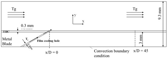
Figure 2.
Computation Model.
As shown in Figure 2, hot gas convection heat transfer with TBC and cooling air enters the fluid domain from the film-hole to simulate the film-cooling effect; meanwhile, the convection heat transfer boundary conditions are set in the internal metal surface. Hence, the working state of the outer film heat transfer–TBC–internal heat transfer downstream of the film-hole can be approximately simulated.
3.2. Computational Technique
The computational domain is meshed by a structured grid and the boundary layer grid is locally refined on the film-hole and external surface of TBC in order to let first layer . The simulation adopts the shear stress transport (SST) k-ω turbulence model, which has been employed and proven to be able to predict the temperature distribution of vane with film cooling [23,24,25,26]. To confirm mesh independence, we chose mesh numbers 107041 via the cases with mesh numbers ranging from 4554 to 157950 in Figure 3.
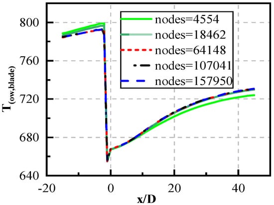
Figure 3.
Mesh independence.
The mainstream and coolant film flow mediums are regarded as compressible ideal gases. The inlet boundary condition is set as the speed inlet boundary condition, the temperature of the main flow and film gas are set to 1082 K and 653 K, respectively, the mainstream inlet velocity is 20 m/s, and the coolant film flow inlet velocity is set up based on the blowing ratio. The outlet is set to a pressure boundary condition of 101,325 Pa, and the thermal conductivity of the coating refers to [27], which is set according to the different thermal resistance ratio. When the physical parameters of the coating material are set according to the metal, it is regarded as uncoated. The boundary condition of convective heat transfer is set on the inner surface of the metal, and the value of the internal heat transfer coefficient h2 is 5000~15,000 W/(m2∙K). The interface between the solid domain and fluid domain is set as a coupled heat transfer boundary condition. The remaining surfaces are set as adiabatic boundary conditions. All the boundary condition show in Table 1.

Table 1.
Boundary Condition.
3.3. Parameters Setting
The film adiabatic cooling effectiveness and overall cooling effectiveness is defined as:
Furthermore, and are the temperatures of hot gas and coolant gas, respectively, represents the adiabatic temperature of external TBC surface, and is the temperature of the external metal surface.
The blowing ratio M and thermal resistance ratio is defined as:
Furthermore, the blowing ratio reflects the ratio of the mass flow of the film cooling airflow to mainstream hot gas, and the thermal resistance ratio reflects the ratio of thermal resistance of TBC-to-metal.
The temperature-drop of the coating itself and the temperature-drop difference between the external surface of the metal blade with or without coating were defined as:
Additionally, and represent the temperature of the external surface of TBC and metal, respectively, with TBC, and is the temperature of the external blade surface without TBC.
4. Results
The focus points of this paper are to: (1) Obtain the heat transfer mechanism of TBC by a 1-D model, which means that the temperature-drop of the coating itself () is proportional to the temperature-drop difference between the external surface of the metal blade with or without coating (). (2) Discuss the thermal insulation effect of TBC by changing the blowing ratio M, thermal resistance ratio , and internal heat transfer coefficient h2. (3) Analyze the sensitivity the above-mentioned factors to reveal the main factors that affect the thermal insulation effect of TBCs.
4.1. Numerical Verification of Temperature-Drop Equation
Figure 4 shows the variation of and at different BR under and . It indicates that downstream from the film-hole, the temperature-drop of the coating itself () and the temperature-drop difference between the external surface of the metal blade with or without coating () increase significantly as the x/D increases, and then the increasing trend gradually slows down. As BR increases from 0.25 to 0.5, the value of and is reduced; however, there is not much difference between the variation of the two temperature-drops, which shows a relatively good corresponding relationship of the two.
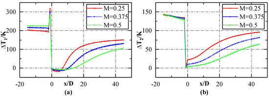
Figure 4.
(a,b) Distribution of and at different BR under , .
In order to verify Equation (5), it is necessary to calculate the temperature-drop of the coating itself () and the temperature-drop difference between the external surface of the metal blade with or without coating () at x/D = 30 under different conditions. Table 2 and Figure 5 shows the comparison of the calculated and theoretical results, in which the temperature-drop ratio matches well under different BR and h2. However, there is a difference in value between the calculated results and theoretical results, which is because the computational model is not an ideal 1-D heat transfer model; thus, heat transferring is in a mainstream direction between the coolant gas in the film-hole with TBC and the metal part. In summary, Equation (5) verifies that variation law is basically the same as the temperature-drop of the coating itself () and the temperature-drop difference between the external surface of the metal blade with or without coating ().
Table 2.
Computational and theoretical data of under different conditions.
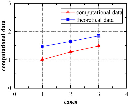
Figure 5.
Computational and theoretical data of under different conditions.
4.2. TBC–Film Cooling Combined Effect and Factor Analysis
Figure 6 shows the results of , , , and with and without TBCs at different BR under and . Figure 6a shows that the overall cooling effectiveness is best at M = 0.5 with TBC under different BR and with or without TBC. By comparing the two working conditions of film cooling only and TBC–film cooling combined, it can be found that the TBC can slow down the film-cooling effect as x/D increases, thus, making the temperature distribution tend to be uniform. Comparing the four conditions of film cooling without TBC, film cooling alone, TBC alone, and the two together, all scenarios can contribute to the overall cooling effectiveness, and the combined effect of the two is better than that of each alone. This indicates that the coupling effect of TBC–film cooling is the best, and that TBC can be designed in combination with film cooling to work together.
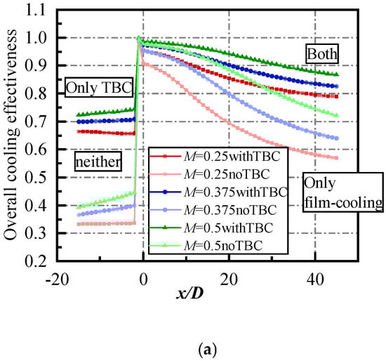
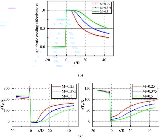
Figure 6.
Results under and ; (a) distribution of with or without TBC at different BR under and ; (b) distribution of at different BR under and ; (c) distribution of and under and .
However, when comparing Figure 6b,c, it can be found that becomes highly smaller as the x/D increases, and then the decreasing trend gradually slows down; this variation rule is contrary to the variation rules of and , indicating that TBC and film cooling may weaken each other’s effect. Figure 6a illustrates that TBC has a poor thermal insulation effect at the near-exit of the film-hole with high cooling effectiveness, while at a distance, TBC has a significant effect. It further reveals that TBC and film cooling can be integrated to have a better cooling effect than each alone, but they can only play an effect of .
Figure 7 points out that the overall cooling effectiveness is best at M = 0.5 with TBC under h2, varying from to , and with the increase in h2, the is improved under all conditions. By comparing the overall cooling effect of M = 0.5 without TBC and M = 0.25 with TBC, it can be obtained that the former at a location near the exit of the film-hole is higher than the latter, while the two are equal distally under . With the increase in h2, the gap between the two at the near-exit of the film-hole narrows, while the of the former is lower than the latter distally, and the gap becomes increasingly larger. Hence, it can be demonstrated initially that the effect of variation of the internal heat transfer coefficient h2 on the BR and TBC may not be consistent.
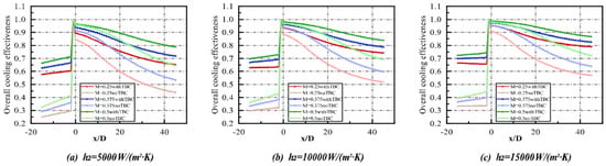
Figure 7.
Distribution of with or without TBC at different BR and h2 at .
Figure 8 depicts the gap between the overall cooling effectiveness of M = 0.5 and M = 0.25, defining . It shows that the gap with TBC is smaller than the one without TBC, meaning that TBC weakens the effect of BR on the overall cooling effectiveness ; thus, TBC weakens the effect of film cooling on the overall cooling effectiveness. Figure 9 shows the gap between the overall cooling effectiveness with and without TBC under different h2. It demonstrates that the gap becomes smaller with increasing BR under different internal heat transfer coefficients, meaning that the increase in BR weakens the effect of TBC on the overall cooling effectiveness ; thus, the improved effect of film cooling weakens the effect of TBC on the overall cooling effectiveness. These two points further prove that TBC and film cooling can only play an effect of .
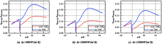
Figure 8.
Distribution of at under different h2.
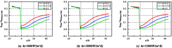
Figure 9.
Distribution of at different BR under and different h2.
Furthermore, Figure 8 and Figure 9 show that the variation of internal heat transfer coefficient does not affect the gap between the overall cooling effectiveness of M = 0.5 and M = 0.25 and the gap between the overall cooling effectiveness with and without TBC under different x/D. However, Figure 8 demonstrates that the gap between the overall cooling effectiveness of M = 0.5 and M = 0.25 becomes smaller with increasing h2 whether it is with TBC or not, meaning that an increase in h2 weakens the effect of BR on overall cooling effectiveness . Furthermore, it can be shown in Figure 9 that the gap between the overall cooling effectiveness with and without TBC is basically unchanged under h2, varying from to . Thus, the variation of the internal heat transfer coefficient basically does not affect the contribution of TBC on the overall cooling effectiveness.
Figure 10 shows the effect of thermal resistance ratio on the overall cooling effectiveness at different BR under . This indicates that the overall cooling effectiveness improves with the thermal resistance ratio increasing at different BRs. However, while the thermal resistance ratio becomes larger, the effect on the overall cooling effectiveness of the same increase in thermal resistance ratio becomes smaller. Furthermore, comparing the effect of on under different BR illustrates that with the BR increasing, the improves under each , while the improvement caused by an increase in the same results becomes smaller; thus, indicating that the increase in BR weakens the influence of the variation of the thermal resistance ratio on the overall cooling effectiveness.
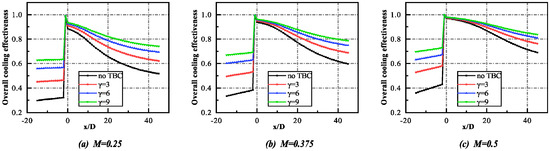
Figure 10.
Effect of on at different BR under .
Figure 11 shows the effect of the thermal resistance ratio on the overall cooling effectiveness at different h2 under M = 0.375. It shows, as mentioned above, that the overall cooling effectiveness improves with the thermal resistance ratio increasing at different h2. However, while the thermal resistance ratio becomes larger, the effect on the overall cooling effectiveness of the same increase in the thermal resistance ratio becomes smaller. Meanwhile, the improves under each with the increase in h2. Figure 12 shows the gap between the overall cooling effectiveness of and under different BRs and h2. It reveals that the gap is basically the same at the same BR with the variation of h2; thus, the increase in the internal heat transfer coefficient can improve the overall cooling effectiveness as a whole, but will not affect the improvement of on the overall cooling effectiveness. In addition, Figure 12 can further illustrate that an increase in BR weakens the effect of on the overall cooling effectiveness ; thus, the improved effect of film cooling weakens the effect of TBC on the overall cooling effectiveness.
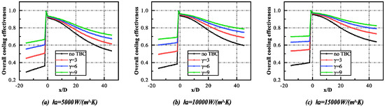
Figure 11.
Effect of on at different h2 under M = 0.375.
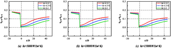
Figure 12.
Distribution of under different BRs and h2.
4.3. TBC–Film Cooling Combined Effect and Multiple Factors Sensitivity Analysis
Due to the complex mechanisms of aero-engines, there are many factors that affect the performance of the engine with the mechanism having not been clarified. In order to solve many ‘bottleneck’ problems of the engine, it is often necessary to find the key factors that affect the problem among many influencing factors. At this time, sensitivity analysis is increasingly used in the research of aero-engines, especially related research on the analysis of the effects of multiple factors of internal and external coupled heat transfer.
Williams, R. et al. [28] analyzed the sensitivity of the overall cooling effect of the scheme coupled by film cooling and internal cooling at the suction surface of the turbine blade; additionally, they connected the Biot number Bi and internal and external heat transfer coefficient with the overall cooling effectiveness by deriving formula, and then tested it by numerical simulation and through the experiment. Prapamonthon, P. et al. [29] used numerical approaches to obtain the separate and combined effects of surface roughness and thermal barrier coating on the vane cooling performance; in addition, thermal sensitivity was used to analyze the roughness height and TBC based on the volume basis in the roughness height, with the range extending from 5 to 120 µm. Wang, C. et al. [30] studied present quantification analysis of the impact of geometric uncertainty on film cooling performance at the blowing ratio of 0.5 and 1.5; in addition, they pointed out that the increase in blowing ratio results in the increase in the uncertain degree of adiabatic film-cooling effectiveness by numerical and experimental studies and the Monte Carlo simulation. Zyla, B. et al. [18] studied a 1-D theoretical model to acquire the influence of parameters on the performance of TBCs, and established a 3-D model of guide vane with TBC based on the fluid–solid coupling method to evaluate the thermal insulation effect and thermal stress of TBC. Wang, J.H. et al. [31] studied the combined effects of the internal element layout, coating thickness and cooling air amount on the metal and TBC surface temperatures, and obtained that when adopting the TBCs with relative to the coolant amount and TBC thickness, the sensitivities of cooling effectiveness with internal layout were non-significant.
This paper adopts the sensitivity analysis method of orthogonal experimental design in Design of Experiments (DOE). Orthogonal experimental design uses a standardized orthogonal table to rationally arrange experiments and uses mathematical statistics to analyze experimental results scientifically and deal with multiple factors. Its advantage is that it can clarify the influence of each factor on the test index through a few experiments with strong representativeness, determining the priority of the factors, and gives the optimal parameter combination [32,33,34]. This paper uses orthogonal experimental design to analyze the contribution sensitivity of three forms of external film heat transfer, thermal barrier coating heat insulation, and internal heat transfer to the overall cooling effect under a designed working condition. Specifically, using the variation of the blowing ratio , the thermal resistance ratio , and the internal heat transfer coefficient to represent the effect of external film cooling, thermal insulation of TBCs and the effect of internal heat transfer, respectively, can analyze the sensitivity of the above influencing factors on the overall cooling effectiveness.
The above influencing factors are divided into low, medium, and high levels, and the overall cooling effect at three different dimensionless distances x/D is chosen as the evaluation index to sensitivity analysis—the result is shown in Figure 13. It shows that film cooling plays a major role in the contribution of the overall cooling effectiveness near the exit of the film-hole, at x/D = 10, while the contribution of TBC is small. However, the contribution of TBC and the internal heat transfer coefficient to overall cooling effectiveness gradually improves as the x/D increases, among which the contribution of TBC improves significantly. The results reveal that TBC has a poor contribution on the overall cooling effect for the area near the exit of the film-hole where the effect of film cooling is good. However, the contribution becomes larger at a distance from the film-hole where the effect of film cooling is poor, on which we should spray TBCs to protect the metal blade.
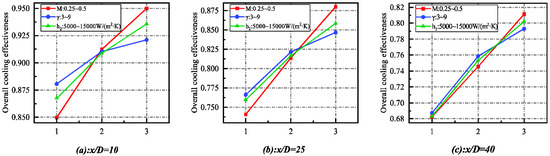
Figure 13.
Sensitivity analysis result at three x/D.
5. Conclusions
This paper establishes a 1-D heat transfer model to evaluate the thermal insulation of TBCs under different factors. It is necessary to find the relationship between the temperature-drop of the coating and the temperature-drop difference between the external surface of the metal blade with or without coating in order to find the shortcomings of current evaluating standards for TBCs and obtain a more reasonable standard in evaluating the thermal insulation effect of TBC. Furthermore, it is necessary to verify the correlation formula by numerical simulation and find the combined effect with thermal insulation of TBCs and internal and external heat transfer. Then, it is necessary to obtain the influence of them and analyze the sensitivity of their effect on the overall cooling effect. The following are specific conclusions:
- (1)
- We theoretically obtained and numerically verified the relationship between the temperature-drop of the coating itself (). This is a current evaluation of the TBC effect and temperature-drop difference between the external surface of the metal blade with or without coating (), of which aero-engines really consider. Further, we obtained the corresponding increase in turbine inlet temperature. This has a certain reference value to understand the thermal insulation mechanism of the TBC, and can help to further establish a more reasonable evaluation of the TBC effect.
- (2)
- TBC and film cooling can be integrated to have a better cooling effect than each alone, but they can only play an effect of . However, the gap with TBC is smaller than the one without TBC, which means that TBC weakens the effect of BR on the overall cooling effectiveness , that is, TBC weakens the effect of film cooling on the overall cooling effectiveness. Meanwhile, the gap between the overall cooling effectiveness with and without TBC becomes smaller, with BR increasing under a different internal heat transfer coefficient; thus, meaning that the increase in BR will weaken the effect of TBC on the overall cooling effectiveness , that is, the improved effect of film cooling will weaken the effect of TBC on the overall cooling effectiveness. These two points further prove that TBC and film cooling can only play an effect of .
- (3)
- The overall cooling effectiveness improves as the thermal resistance ratio increases. In addition, when the thermal resistance ratio becomes larger, the effect on the overall cooling effectiveness of the same increases as the thermal resistance ratio becomes smaller. Furthermore, by comparing the effect of on under different BRs, it illustrates that with the BR increasing, the improvement caused by an increase in the same results in it becoming smaller; thus, indicating that the increase in BR will weaken the influence of the variation of the thermal resistance ratio on the overall cooling effectiveness. Meanwhile, the gap is basically the same at the same BR with the variation of h2, which means that the increase in the internal heat transfer coefficient will basically not affect the improvement of on the overall cooling effectiveness.
- (4)
- We chose the overall cooling effect at three different dimensionless distances x/D as the evaluation index to analyze the sensitivity of the variation of the blowing ratio , the thermal resistance ratio , and the internal heat transfer coefficient to represent the effect of external film cooling, thermal insulation of TBCs, and the effect of internal heat transfer, respectively. We analyzed the sensitivity of the above influencing factors on overall cooling effectiveness. It was found that film cooling plays a major role in the contribution of the overall cooling effectiveness near the exit of the film-hole, at x/D = 10, while the contribution of TBC is small. However, it was found that the contribution of TBC and internal heat transfer coefficient to overall cooling effectiveness gradually improves as the x/D increases, among which the contribution of TBC improves significantly.
Author Contributions
Methodology, Y.L.; Project administration, H.L.; Writing—original draft, C.G.; Writing—review & editing, R.Y. All authors have read and agreed to the published version of the manuscript.
Funding
The present work is financially supported by the National Natural Science Foundation of China (No.51906008) and the Fundamental Research Funds for the Central Universities (No. YWF-21-BJ-J-822), and National Science and Technology Major Project (2017-III-0003-0027).
Conflicts of Interest
The authors declare no conflict of interest.
References
- Chen, M. The development of Aero-engine technology. Sci. Chin. 2015, 28, 10–19. [Google Scholar]
- Deng, H. Experimental Study on the Heat Transfer Characteristics of the Cooling System in the Middle of a Turbine Blade; Beihang University: Beijing, China, 2004. [Google Scholar]
- Matsumoto, K.; Itoh, Y.; Kameda, T. EB-PVD Process and Thermal Properties of Hafnia-Based Thermal Barrier Coating. Sci. Technol. Adv. Mater. 2003, 4, 153. [Google Scholar] [CrossRef]
- Qin, J.; Chen, G.; Du, Z.M.; Jin, Y.H. Study on Performance of 8YSZ Thick Gradient TBC. Appl. Mech. Mater. 2014, 607, 43–46. [Google Scholar] [CrossRef]
- Wang, Y.; Li, J.; Liu, H.; Weng, Y. Study on Thermal Resistance Performance of 8YSZ Thermal Barrier Coatings. Int. J. Therm. Sci. 2017, 122, 12–25. [Google Scholar] [CrossRef]
- Demasi-Marcin, J.T.; Gupta, D.K. Protective Coatings in the Gas Turbine Engine. Surf. Coat. Technol. 1994, 68, 1–9. [Google Scholar] [CrossRef]
- Guo, H.; Gong, S.; Xu, H. Progress in Thermal Barrier Coatings for Advanced Aeroengines. Mater. China 2009, 9, 18–26. [Google Scholar]
- Meier, S.M.; Gupta, D.K. The Evolution of Thermal Barrier Coatings in Gas Turbine Engine Applications. J. Eng. Gas Turbines Power 1994, 116, 250–257. [Google Scholar] [CrossRef]
- Davidson, F.T.; Dees, J.E.; Bogard, D.G. An Experimental Study of Thermal Barrier Coatings and Film Cooling on an Internally Cooled Simulated Turbine Vane. In Proceedings of the ASME 2011 Turbo Expo: Turbine Technical Conference and Exposition, Vancouver, BC, Canada, 6–10 June 2011. [Google Scholar]
- Padture, N.P.; Gell, M.; Jordan, E.H. Materials Science—Thermal Barrier Coatings for Gas-Turbine Engine Apptications. Science 2002, 296, 280–284. [Google Scholar] [CrossRef]
- Prapamonthon, P.; Xu, H.; Yang, W.; Wang, J. Numerical Study of the Effects of Thermal Barrier Coating and Turbulence Intensity on Cooling Performances of a Nozzle Guide Vane. Energies 2017, 10, 362. [Google Scholar] [CrossRef]
- Lawson, S.A.; Thole, K.A.; Okita, Y.; Nakamata, C. Simulations of Multi-Phase Particle Deposition on a Showerhead with Staggered Film-Cooling Holes. J. Turbomach. 2012, 134, 051041.1–051041.12. [Google Scholar] [CrossRef]
- Albert, J.E.; Bogard, D.G. Experimental Simulation of Contaminant Deposition on a Film Cooled Turbine Vane Pressure Side with a Trench. J. Turbomach. 2013, 135, 051008.1–051008.11. [Google Scholar] [CrossRef]
- Ekkad, S.V.; Han, J.C. Heat Transfer Distributions on a Cylinder with Simulated Thermal Barrier Coating Spallation. J. Thermophys. Heat Transf. 2015, 13, 76–81. [Google Scholar] [CrossRef]
- Maikell, J.; Bogard, D.; Piggush, J.; Kohli, A. Experimental Simulation of a Film Cooled Turbine Blade Leading Edge Including Thermal Barrier Coating Effects. In Proceedings of the ASME Turbo Expo 2009: Power for Land, Sea, and Air, Orlando, FL, USA, 8–12 June 2009. [Google Scholar]
- Han, Z.X.; Dennis, B.H.; Dulikravich, G.S. Simultaneous Prediction of External Flow-Field and Temperature in Internally Cooled 3-D Turbine Blade Material. Int. J. Turbo Jet Engines 2001, 18, 47–58. [Google Scholar] [CrossRef]
- Zhu, W.; Wang, J.W.; Yang, L.; Zhou, Y.C.; Wei, Y.G.; Wu, R.T. Modeling and Simulation of the Temperature and Stress Fields in a 3D Turbine Blade Coated with Thermal Barrier Coatings. Surf. Coat. Technol. 2017, 315, 443–453. [Google Scholar] [CrossRef]
- Liu, Z.Y.; Zhu, W.; Yang, L.; Zhou, Y.C. Numerical Prediction of Thermal Insulation Performance and Stress Distribution of Thermal Barrier Coatings Coated on a Turbine Vane. Int. J. Therm. Sci. 2020, 158, 106552. [Google Scholar] [CrossRef]
- Sadowski, T.; Golewski, P. The Influence of Quantity and Distribution of Cooling Channels of Turbine Elements on Level of Stresses in the Protective Layer TBC and the Efficiency of Cooling. Comput. Mater. Sci. 2012, 52, 293–297. [Google Scholar] [CrossRef]
- Shih, I.P. Biot-Number Analogy for Design of Experiments in Turbine Cooling. J. Turbomach. 2015, 137, 061002. [Google Scholar]
- Mensch, A.; Thole, K.A.; Craven, B.A. Conjugate Heat Transfer Measurements and Predictions of a Blade Endwall with a Thermal Barrier Coating. J. Turbomach. 2014, 136, 121003.1–121003.11. [Google Scholar] [CrossRef]
- Eifel, M.; Caspary, V.; Hönen, H.; Jeschke, P. Experimental and Numerical Analysis of Gas Turbine Blades with Different Internal Cooling Geometries. In Proceedings of the ASME Turbo Expo 2009: Power for Land, Sea, and Air, Orlando, FL, USA, 8–12 June 2009. [Google Scholar]
- Ke, Z.; Wang, J. Numerical Investigations of Pulsed Film Cooling on an Entire Turbine Vane. Appl. Therm. Eng. 2015, 87, 117–126. [Google Scholar] [CrossRef]
- Du, K.; Li, J. Numerical Study on the Effects of Slot Injection Configuration and Endwall Alignment Mode on the Film Cooling Performance of Vane Endwall. Int. J. Heat Mass Transf. 2016, 98, 768–777. [Google Scholar] [CrossRef]
- Xiao, X.; Wang, P.; Du, Q.; Xu, Q.; Liu, J.; Zhu, J. Numerical Investigations of Film Cooling Characteristics of Interrupted Slot and Trench Holes on a Vane Endwall. J. Therm. Sci. 2021, 30, 1010–1024. [Google Scholar] [CrossRef]
- Lynch, S.P.; Thole, K.A.; Kohli, A.; Lehane, C. Computational Predictions of Heat Transfer and Film-Cooling for a Turbine Blade with Nonaxisymmetric Endwall Contouring. J. Turbomach. 2011, 133, 041003.1–041003.10. [Google Scholar] [CrossRef]
- Alizadeh, M.; Izadi, A.; Fathi, A. Sensitivity Analysis on Turbine Blade Temperature Distribution Using Conjugate Heat Transfer Simulation. J. Turbomach. 2014, 136, 011001. [Google Scholar] [CrossRef]
- Williams, R.P.; Dyson, T.E.; Bogard, D.G.; Bradshaw, S.D. Sensitivity of the Overall Effectiveness to Film Cooling and Internal Cooling on a Turbine Vane Suction Side. J. Turbomach. 2014, 136, 031006.1–031006.7. [Google Scholar] [CrossRef]
- Prapamonthon, P.; Yin, B.; Yang, G.; Zhang, M. Separate and Combined Effects of Surface Roughness and Thermal Barrier Coating on Vane Cooling Performance. J. Therm. Sci. Eng. Appl. 2020, 12, 051017. [Google Scholar] [CrossRef]
- Wang, C.; Sun, X.; Zhang, J. Uncertainty analysis of trench film cooling on flat plate. Appl. Therm. Eng. 2019, 156, 562–575. [Google Scholar] [CrossRef]
- Huang, X.; Pu, J.; Wang, J.H.; Qu, Y.F.; He, J.H. Sensitivity analysis of internal layout and coating thickness to overall cooling performances of laminated cooling configurations with surface thermal barrier coatings. Appl. Therm. Eng. 2020, 181, 116020. [Google Scholar] [CrossRef]
- Shi, Y. Probability Theory and Mathematical Statistics, 4th ed.; Northwestern Polytechnical University Press: Xi’an, China, 2012. [Google Scholar]
- Yang, D. Experimental Design and Analysis; China Agricultural Press: Beijing, China, 2002; pp. 1–14. [Google Scholar]
- Li, Y.; Hu, C. Experimental Design and Data Processing; Chemical Industry Press: Beijing, China, 2005; pp. 79–83. [Google Scholar]
Publisher’s Note: MDPI stays neutral with regard to jurisdictional claims in published maps and institutional affiliations. |
© 2022 by the authors. Licensee MDPI, Basel, Switzerland. This article is an open access article distributed under the terms and conditions of the Creative Commons Attribution (CC BY) license (https://creativecommons.org/licenses/by/4.0/).