Abstract
In order to ensure the safety and extend the lifecycle of lithium-ion power batteries in electric vehicles, a battery thermal management system based on minichannel liquid cooling is proposed to cool rectangular lithium-ion batteries, and a three-dimensional cooling system model is established. The effects of the number of channels, the thickness of heat conducting silicone grease and the thermal conductivity of the battery itself on the temperature rise and voltage drop changes during the discharge process of the battery are studied. The results show that the maximum temperature of the battery decreases with the increase of the number of channels, and the voltage drop inside the channel increases with the increase of the number of channels. The maximum temperature of the battery increases with the increase of the thickness of the thermal grease, but the increase is only 1.26 K. The maximum temperature and local temperature difference of the battery change significantly with the change of the thickness of the battery and its own thermal conductivity. The simulation results will be beneficial to the design of a battery thermal management system based on minichannel liquid cooling.
1. Introduction
Nowadays, greenhouse gases and pollutions released by fossil fuels are significant, which necessitate the development of new and renewable energy sources. The transportation industry is maneuvering towards sustainable and low-carbon automobiles, such as pure electric vehicles driven by energy storage batteries, to achieve the goal of carbon neutrality [1,2,3]. Lithium-ion batteries are the most popular and have acquired enormous attention as a power source for electric vehicles thanks to their performance superiority, for example, a higher energy density, truncated self-discharge rate, strengthened lifetime and reposeful discharge plateau [4,5,6]. However, lithium-ion batteries are sensitive to temperature because of complex and continuous electrochemical–thermal coupled reactions during the discharging process, such that both higher or lower temperatures will attenuate the performance and shorten the lifecycle. Especially for higher temperatures, thermal runaway may be triggered, causing fire or even explosion accidents. Therefore, establishing an effective thermal management system and regulating the operating temperature of lithium-ion batteries in a safe and appropriate range, 25–40 °C for a maximum temperature and lower than 5 °C for a minimum temperature difference, as given in [7,8,9], is indispensable.
Recently, various thermal management technologies were adopted to mitigate the thermal issues and render the temperature of the battery within an optimal range, such as phase change material (PCM)-based [10,11], air-based [12,13], liquid-based or hybrid thermal management technologies [14]. The PCM-based battery thermal management system is a kind of passive method which shows some merits, including zero energy consumption for cooling medium circulation and no requirement of additional auxiliary components [15]. As the most mature thermal management technology, the lower heat transfer coefficient and the air-cooling system’s sensitivity to the environmental temperature seriously restricts the applicability, especially for batteries discharged at a higher rate.
Among the above thermal management technologies, the liquid cooling system presents an excellent performance result from the outbound heat transfer efficiency and reliability. Su et al. built a computational fluid dynamics model to analyze the influence of the cooling plate thickness, the cooling plate wall thickness, the inlet coolant temperature and the flow velocity based on the comprehensive performance of the battery’s thermal management system [16]. In order to accurately calculate the heat generation rate of the battery, an electrochemical model and a heat transfer model were coupled so to analyze the effect of the flowing parameters and the structure parameters of the cold plate on the cooling efficiency of the system [17]. Generally, increasing the mass flow rate is an efficient way to enhance the heat transfer performance. Nevertheless, this inevitably leads to parasitical energy consumption resulting from the pump work. Optimizing the structure of the liquid cold plate was an effective method to improve the cooling effect with lower additional energy consumption. Jiang et al. [18] used the mini V-shaped ribs to optimize the structure of the liquid cold plate and the result showed that this way can improve the Nusselt Number and the Friction Factor of the channels compared with those of the smooth channel and the channel with a straight rib. As shown in Ref. [19], the cooling plate with a convex structure has a better cooling performance than the honeycomb structure, the airfoil structure and the U-shaped structure. Except for the flow parameter, the structure of the cold plate or the channels and the arrangement of the pack, it has also been verified that the coolant category has a significant influence on the cooling performance of the cooling system. For example, water [20], R134a [21], hydrogen [22] and HFE7000 [23] present different cooling effects when used in various cooling systems.
Heat removal from a battery is determined by the heat conduction in the battery and the heat convection from the battery surface to the coolant. Therefore, the causes affecting the performance of the liquid-based thermal management system include external factors which mainly determine heat convection on the battery surface, including the arrangement of the battery pack, the structure of the cold plate or the channels and the flowing parameters, including the mass flow rate, the category of the coolant or the inlet temperature [24]. Simultaneously, the internal factors, namely the thermophysical properties of the lithium-ion battery, such as the characteristics of thermal conductivity, have a profound impact on the heat conduction within the battery [25]. For the Li-ion battery, thermal conductivity is anisotropic [26], that is, the thermal conductivity in an out-of-plane direction is poor because heat from the core to the surface must pass through layers, including electrodes, the separator current collectors and the contact resistance between different layers. Comparatively, thermal conductivity in the in-plane direction is much higher. However, this is determined by the structure of the Li-ion battery, and the available surface for the heat transfer from the batteries to the coolant is normal for the out-of-plane direction [27]. This means the poor thermal conductivity in the out-of-plane direction, as well as the thickness of the batteries, are significant to the performance of the BTMS. This will lead to a higher temperature gradient in the out-of-plane direction. This temperature gradient may aggravate the electrochemical performance of the batteries and lead to degradation. The other factors influencing the heat transfer process of the Li-ion to the cold plate is the thermal contact resistance [28], the untight contact between the batteries and the metal cold plate, which can be important in determining the effectiveness.
However, the existing works mainly focus on the external factors, as summarized above, and there has been no complete heat transfer process analysis considering the anisotropy of thermal conductivity and contact resistance. In the present manuscript, a minichannel-based liquid cooling battery thermal management system was designed and a computational fluid dynamic (CFD) model was built. Firstly, the width and number of channels was determined. Then, the performance was comprehensively analyzed based on a complete thermal resistance network considering the effect of the internal thermal resistance and the contact thermal resistance.
2. Model and Methodology
2.1. Physical Problem
The whole structure of the liquid cooling-based battery thermal management system (BTMS) is shown in Figure 1. Figure 1a shows the distribution structure of the battery packs in electric vehicles, where batteries are usually used in the form of a pack in practical application. Figure 1b illustrates the structure of the whole cooling system. The cold plates are made of aluminum and distributed on both sides of the battery, and thermal grease is added between the cold plate and the battery. In this study, because this model was axial symmetrically arranged, took the structure shown in the Figure 1c, which included the half battery on the right side, the cold plate in the middle and the half battery on the left side.
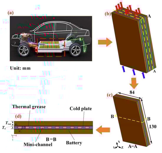
Figure 1.
Schematic of the cooling system: (a) New energy vehicle with battery pack structure. (b) Liquid-cooled battery module. (c) Partial cooling system. (d) Partial cooling system section.
In this simulation, a LiFePO4 battery with the nominal capacity of 9 Ah was considered. Its thickness, width and height were 6 mm, 84 mm and 130 mm, respectively. The thickness of the cold plate was 3 mm, and the height and width were the same as the battery. The channels were evenly distributed in the cold plate. The width of the cold plate was 84 mm, and when the number of channels were 2, 4, 6 and 10, the corresponding channel widths were 20 mm, 10 mm, 6.7 mm and 4 mm, respectively, and the distances between the adjacent channels were 14.6 mm, 8.8 mm, 6.25 mm and 4 mm, respectively. Moreover, the thickness of the thermal grease was considered between the battery and the cold plate. When there was thermal grease, the thickness of thermal grease was considered as 0.1 mm, 0.3 mm, 0.6 mm, 1 mm and 2 mm. For the thermal resistance of the battery, four different thicknesses of the battery were designed, and the thickness of the battery was expressed by Tbatt, which were 5 mm, 6 mm, 7.5 mm and 10 mm, respectively, while four different thermal conductivities of the battery were designed, which were 0.1 W m−1 K−1, 0.2 W m−1 K−1, 0.3 W m−1 K−1 and 0.4 W m−1 K−1, respectively.
2.2. Mathematical Model
In this research, the battery was rectangular in shape, and heat was generated from the cell transfers into the cold plate through the contact surface, then dissipated into the coolant of water, which flows through the minichannel [29,30]. So, this process involved the mass and momentum conservation, with the equations as follows:
Meanwhile, the energy conservation of the coolant was expressed by Equation (3).
where ρl (kg m−3) is the density of the coolant, cp (J kg−1 K−1) is the heat capacity of the coolant and kl (W m−1 K−1) is the thermal conductivity of the coolant.
The energy conservation equation of the battery can be expressed as the following:
where ρb (kg m−3), cpb (J kg−1 K−1) and kb (W m−1 K−1) are the density, specific heat and thermal conductivity of the battery, respectively. It should be emphasized that the anisotropy of the thermal conductivity was considered; namely, ky was much less than kx and kz. Additionally, the thermal conductivity in the thickness direction ky was a variable in the present research.
Additionally, due to the battery side, a convective boundary condition existed, and the amount of heat dissipated due to the movement of a fluid can be expressed using Equation (5):
where Ta (K) is the ambient temperature, ha (W m−2 K−1) is the convective heat transfer coefficient of air and qa (W m−2) is the heat flux.
The lithium-ion battery generates a large amount of heat due to electrochemical reactions under charge and discharge working conditions. Heat generation during the charging and discharging process in the lithium-ion battery mainly consists of three parts: joule heat, chemical reaction heat and polarization heat. The heat generation rate was calculated using Equation (6) and the related parameters were gained from experiment [31,32].
where q (W m−3) is the heat generation rate, Vbatt (m3) is the volume of the battery cell, U (V) is the terminal voltage, UOC (V) is the open circuit voltage and ∂UOC/∂T is the entropy coefficient of the heat.
The first term to the right of the equal sign of Equation (6) represents the joule heat due to the ohmic resistance and the polarization heat due to polarization resistance inside the battery cell, which led to a difference between U and UOC. So, Equation (6) was simplified to
Among the parameters, the value related to the battery’s own characteristics was ∂UOC/∂T, and the maximum thermal entropy coefficient was taken as 0.2225 mV/K, which was experimentally measured in Ref. [20]. In order to ensure the margin, the maximum thermal entropy coefficient was used to calculate the maximum heat production, which can be met in the cooling system, so the actual heat production can also be met. The internal resistance of the battery was a certain value, which was 15 mΩ [33]. In this paper, the discharge rate of the theoretical operation of the electric vehicle was considered to be 3C, and for a 9 Ah battery, the discharging current was 27 A; based on the above thermal entropy coefficient value and resistance value, the generation rate was 89,370 W m−3.
2.3. Initial Condition and Boundary Condition
In this simulation, the battery was assumed to be fully discharged under the constant current mode, with a discharge rate of 3C and discharge time lasting 1200 s. Meanwhile, the velocity inlet and pressure outlet boundaries were used for the inlet and the outlet of the coolant flow in the minichannels, respectively. The inlet velocity was 0.05 m/s and the gauge pressure at the outlet was 0 Pa. The walls between the different subdomains (the battery body and the thermal grease, the thermal grease and cold plate, the cold plate and the minichannels) were defined as the thermal coupled interface. The XZ plane of the battery was set as an adiabatic boundary condition, the XY plane of the battery and the cold plate were set as the natural convective boundary condition and the convective heat transfer coefficient was 5 W m−2 K−1, according to the literature [34]. For the initial temperature of the battery, the coolant inlet temperature was 25 °C, which was equal to the ambient temperature.
All the parameters used in the present research are listed in Table 1.

Table 1.
The geometric parameters and physical parameters used in the present research.
2.4. Grid Division and Independence Verification
The CFD software ANSYS Fluent 2022R1 was used to calculate the results. The governing equations were dealt with using a simple method, and the second-order upwind was selected. The maximum iteration step was 20 and the time step was 1 s. The grid of the whole cooling system is shown in Figure 2a. An unstructured grid was employed to discretize the battery model and the cold plate. The independence test of the grid number, which was important to the transient simulation, was firstly carried out on five different grid numbers to ensure the calculation accuracy. Figure 2b shows the results of the test, where the maximum temperature change of the battery was less than 0.05 K when the grid number increased from 6,608,976 to 13,881,024. So, the grid number of 6,608,976 was used in this study.
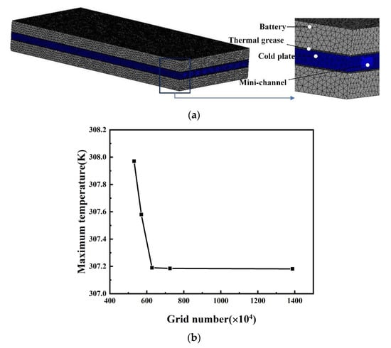
Figure 2.
(a) Unstructured grid and the local enlarged mesh; (b) Grid independence test.
3. Results and Discussions
3.1. The Impacts of the Number of Channels
In this section, the impact of the number of channels in the cold plate on the cooling performance of the battery is discussed. The thickness of the thermal grease and the thickness of the battery were 0.3 mm and 6 mm, respectively, and the thermal conductivity of the battery was 0.2 W m−1 K−1. Four kinds of cold plates with different channels were designed under the same cross-sectional area, and the number of channels was 2, 4, 6 and 10, respectively. It should be emphasized that the cross-section or flow cross area was the same for the cold plates with different channels; namely, when the number of channels changes, the width of a single channel is also changed.
The changed curves of Tm, ∆T and the pressure drop during the 3C discharge process with the different channel numbers are shown in Figure 3. The comparison of the four kinds of cold plates with different channels, due to the channels corresponding to the same flow cross area, changed the number of channels, which had little effect on the cooling performance of the battery, but the variety of the pressure drop was relatively large. It can be seen from Figure 3a,b that, when the number of cooling channels was 2, Tm and ∆T were 307.17 K and 8.19 K at the end of the discharge, respectively. When the channel number was 10, compared with the case of the two channels, Tm decreased by 0.28 K and ∆T decreased by 0.22 K, respectively. Tm and ∆T rose more quickly before 350 s, and it tended to be stable after 650 s, which proved that, under the same cooling area, the change of the number of cooling channels had little effect on the cooling performance. In addition, when the channel width was constant, the cooling performance was improved rapidly by increasing the number of channels [24], which indicated that the cooling area was the main factor affecting the cooling performance of the battery. Figure 3c shows that the pressure drop was 21.77 Pa for the cold plate with two channels, which increased by 40% for the cold plate with 10 channels, and which reached to 30.44 Pa; thus, the variety of the pressure drop was relatively obvious, which demonstrated that the number of channels should be restricted so as to avoid the increased pressure loss and cost. The number of channels had little effect on the cooling performance of the battery; however, with the increased of the number of channels, the increased flow area led to the increased pressure drop.
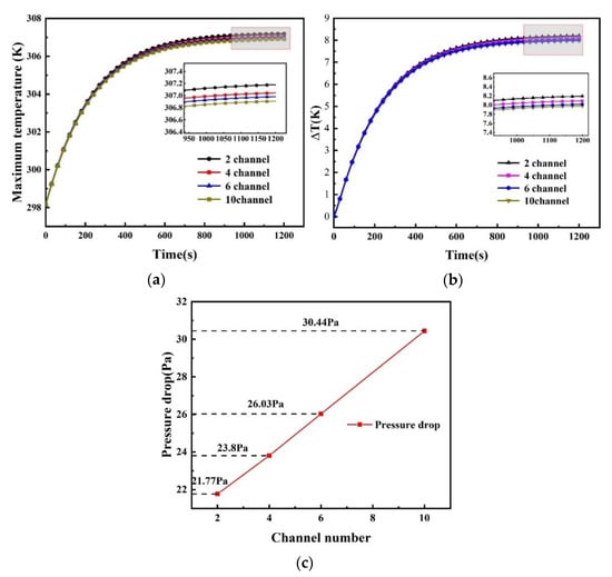
Figure 3.
(a) Maximum temperature; (b) Temperature difference; (c) Pressure drop variations with different number of cooling channels.
Figure 4 shows the simulated temperature fields at the end of the discharge (i.e., after 1200 s), which was the temperature cloud at the height of the X/2 direction in the YZ plane, and the result showed that the temperature gradient of the battery mainly existed in the thickness direction. A lower the temperature near the cold plate along the thickness direction of the battery was observed. Figure 5 shows the temperature cloud in the Y/2 direction in the XZ plane and includes the temperature distribution of the channels and the fluid. It can be found that, with the increased number of channels, the temperature of the cold plate gradually decreased. The cooling channels were evenly distributed along the width direction. The temperature change of the whole cooling channel was 0.27 K. When the cooling number was 2, the temperature at the outlet of the flow channels increased by 3 K.
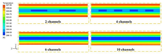
Figure 4.
Temperature cloud at the middle position along the coolant flow direction.
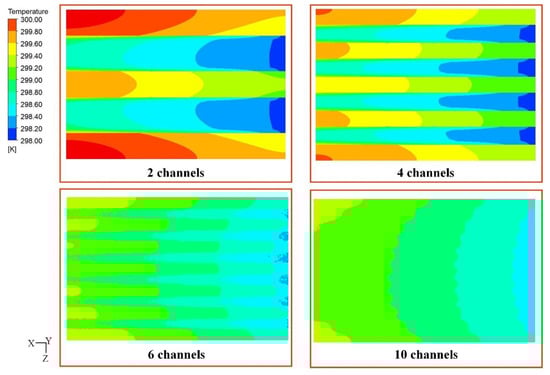
Figure 5.
Temperature cloud at the middle position in the Y direction.
Under the same cooling area, the increased number of channels had little effect on the cooling performance, but it had a great influence on the pressure drop. So, the number of channels should not be too many. In this paper, the optimal number of channels was 10. The temperature cross-sectional view shows that the maximum temperature difference mainly existed in the thickness direction, and from this, we can observe the cooling of the cold plate and the liquid.
3.2. Effect of Thickness of Thermal Grease
In application, because the contact surface between the battery and the cold plate was not smooth, there was a gap between the contact surfaces which was filled with air. Due to the low thermal conductivity of air, there was a large contact thermal resistance between the battery and the cold plate. Adding materials with a high thermal conductivity between the cold plate and the battery, such as thermal grease, would reduce the contact thermal resistance and improve the heat transfer between the battery and the cold plate, thereby improving the cooling performance of the battery. Generally, different kinds of highly thermal conductive fillers were efficient candidates for commercialized TIMs due to the low thermal impedance and low cost [35]. In the simulation, only the effect of the thickness of the thermal grease on the cooling performance of the battery was studied because the contact between the battery and the cold plate was good. The thickness of the thermal grease was expressed by Tsi, and the effects of six kinds of thermal grease with different thicknesses on the cooling performance of the battery were studied. In this section, the number of cooling channels was 10, the thickness of the battery was 6 mm, the thermal conductivity of the battery was 0.2 W m−1 K−1 and the density, specific heat and thermal conductivity of the thermal grease were 2300 kg m−3, 1000 J kg−1 K−1 and 2.4 W m−1 K−1, respectively. When the battery was in rigid contact with the cold plate, the equivalent thickness of the thermal grease was calculated by Equation (8).
where hR (W m−2 K−1) is interfacial thermal conductivity, which is 400 W m−2 K−1 [36], and kg (W m−1 K−1) is the thermal conductivity of thermal, which is 2.4 W m−1 K−1 in this paper [37].
According to Equation (8), the thickness of the equivalent thermal grease was 6 mm when rigid contact was considered between the battery and the cold plate. Figure 6 shows the change curves Tm of and ∆T during the 3C discharge process with different thicknesses of thermal grease. When the thickness was 6 mm, Tm was 308.11 K and ∆T was 7.91 K at the end of the discharge, compared with the thickness of the thermal grease, which was 2 mm, while Tm increased to 0.84 K. The Tm and ∆T of different thicknesses rose more quickly before 400 s, and the trend of the variation of Tm and ∆T was relatively stable after 600 s. Figure 6b shows that the temperature difference for the different thermal contact resistances reaching the maximum value when the time was 400 s, which was 0.437 K. As the thickness of the thermal grease increased from 0 mm to 6 mm, ∆T had little change, which was less than 0.5 K. Although the thickness of the thermal grease had little effect on the cooling performance of the battery, as concluded above, it can be predicted that the influence will be more obvious with the increase of the heat generation rate.
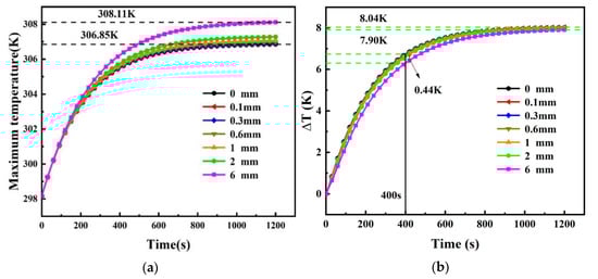
Figure 6.
(a) Maximum temperature and (b) temperature difference variations with different thicknesses of silicone grease.
3.3. Effect of Thermal Resistance of Battery
Compared with the interface contact thermal resistance, the larger thickness and smaller thermal conductivity in the Y direction of the battery itself made the internal thermal resistance of the battery still dominate the heat transfer process in the battery, and the thermal properties, such as the thermal conductivity, dramatically influenced the highest temperature that a cell can safely withstand, as well as the thermal runaway propagation [38]. Firstly, the effect of the battery thickness on the cooling performance was studied, whereby the number of cooling channels was 10, the thickness of the thermal grease was 0.3 mm and the thermal conductivity of the battery was 0.2 W m−1 K−1.
The change curves of Tm and ∆T during the 3C discharge process with the different thicknesses of the battery are shown in Figure 7. It was found that when the thickness of the battery was 10 mm, Tm and ∆T were 318.84 K and 19.67 K, respectively. At this time, Tm exceeded 313.15 K, and it demonstrated that a battery thickness set as 10 mm can cause safety problems and reduce the lifecycle of the battery. The heat generated in the battery cannot be released in time and this results in a larger maximum temperature and poor temperature uniformity. However, for the battery with a thickness 5 mm, Tm increased to 14.4 K and ∆T increased to 14.01 K, respectively, compared with the battery thickness of 10 mm. Figure 7 shows Tm and ∆T increased rapidly before 200 s, and the Tm and ∆T of every thickness design rose slowly after 600 s, especially when the thicknesses were 5 mm and 6 mm. When the thickness of the battery was reduced from 10 mm to 5 mm, the thermal conductivity of the battery was constant; therefore, the thermal resistance of the battery decreased with the decrease of the battery thickness, so that the heat generated by the battery needed to be transferred to the cold plate through a small thermal resistance. Thus, the battery can work within a better temperature range and temperature uniformity. Therefore, when the thermal conductivity of the battery was constant, changing the thickness of the battery had an obvious influence on the cooling performance of the battery.
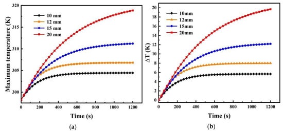
Figure 7.
(a) Maximum temperature and (b) temperature difference variations with different thicknesses of the battery.
Figure 8 shows the simulated temperature fields at the end of the discharge, whereby it was the temperature cloud at the height of the X/2 direction in the YZ plane, and the result proved that the temperature gradient mainly existed in the thickness direction of the battery. It showed that the lower the temperature was near the cold plate along the thickness direction of the battery.
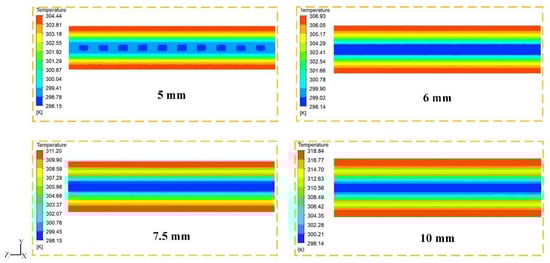
Figure 8.
Temperature contours of different thicknesses of the battery.
In addition, the effect of the thermal conductivity of the battery on the cooling performance was studied, whereby the number of cooling channels was 10, the thickness of the thermal grease was 0.3 mm and the thickness of the battery was 6 mm.
Figure 9 shows the change histogram of Tm and ∆T during the 3C discharging process with different thermal conductivities. When the thermal conductivity of the battery was 0.1 W m−1 K−1, the maximum temperature and temperature difference of the battery were the largest, which were 313.77 K and 15.02 K at the end of the discharge, respectively. Compared with the thermal conductivity at 0.1 W m−1 K−1, when the thermal conductivity was 0.4 W m−1 K−1, the cooling performance of system was the best, which for Tm was 303.09 K and for ∆T was 4.34 K, and the temperature difference also reached the optimal range. The change histogram of Tm and ∆T from 0.2 W m−1 K−1 to 0.4 W m−1 K−1 was small, as Tm changed to 3.84 K and ∆T changed to 3.69 K. On the contrary, when the thermal conductivity increased from 0.1 W m−1 K−1 to 0.2 W m−1 K−1, the change histogram of Tm reduced from 313.77 K to 306.93 K, and there was a falling trend of ∆T from 0.1 W m−1 K−1 to 0.2 W m−1 K−1, whereby ∆T decreased to 8.03 K, such that the variety of the Tm and ∆T histograms was apparent. When the thermal conductivity of the battery was increased from 0.1 W m−1 K−1 to 0.4 W m−1 K−1, the thickness of the battery was constant, and the thermal resistance of the battery decreased with the increase of the thermal conductivity, so that the heat generated by the battery needed to be transferred to the cold plate through a small thermal resistance, which was taken away by the cooling liquid flowing in the channel. In general, when the thickness of the battery was constant, the change in the thermal conductivity had a great impact on the cooling performance of the battery.
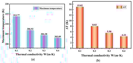
Figure 9.
(a) Maximum temperature and (b) temperature difference variations with different thermal conductivities of the battery.
Figure 10 shows the simulated temperature fields at the end of the discharge, and it was the temperature cloud at the height of the X/2 direction in the YZ plane, whereby the result proved that, when the thickness of the battery was constant, thereby changing the thermal conductivity, the temperature gradient mainly existed in the thickness direction of the battery. It was found that the lower the temperature near the cold plate was along the thickness direction of the battery.
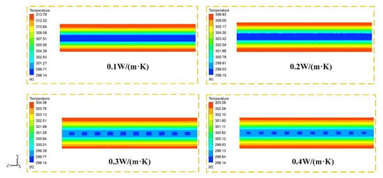
Figure 10.
Temperature contours of different thermal conductivities of battery.
When the thickness of the battery increased from 5 mm to 10 mm, or the thermal conductivity of the battery increased from 0.1 W m−1 K−1 to 0.4 W m−1 K−1, the temperature changed obviously. For the lithium-ion battery, the temperature difference was very large because the thermal resistance of the battery in the thickness direction was large. At the same time, when the discharge rate was 3C, the battery had a low heat generation rate, which made the variety of the external convection heat transfer coefficient have little impact on the battery temperature.
Based on the research in this paper, from the perspective of cost and temperature management, the case of 10 channels had the best cooling performance for the battery, and more channels will increase the pressure drop in the channels, leading to an increase in cost. The smaller the thickness of the battery and the larger the thermal resistance, the better the cooling performance of the battery. Therefore, the optimal configuration was that the number of channels was 10, the thickness of the thermal grease was 0.1 mm, the thickness of the battery was 10 mm and the thermal conductivity was 0.4 W m−1 K−1.
4. Conclusions
In order to reduce the maximum temperature and local temperature difference of the lithium-ion battery during the 3C discharge process, the effects of the number of channels, the thickness of thermal grease and thermal resistance of the battery on the cooling performance were analyzed. Relevant results from this study include:
- (1)
- Under the same flow area, with the number of cooling channels increased, the maximum temperature and the temperature difference of the battery at the end of the discharge decreased, but the trend was small. Instead, the pressure drops in the channel increased obviously due to the increase of the flow resistance. Therefore, the optimal number of channels was 10 in this study.
- (2)
- In this paper, effect of the thickness of the thermal grease on the cooling performance also got smaller. When the thickness increased, it had poor temperature uniformity inside the battery. In practical applications, since there was contact from the thermal resistance between the battery and the cold plate, adding thermal grease in the middle can reduce the impact of the contact thermal resistance, and the smaller the thickness of the thermal grease, the better the cooling performance of the battery.
- (3)
- The thickness of the battery and its own thermal conductivity had more obvious effects on the cooling performance. In this paper, when the thickness of the battery was 10 mm and the thermal conductivity was 0.4 W m−1 K−1, the cooling effect of the battery was the best. So, the thermal resistance of the battery played a leading role in the total thermal resistance of the battery’s thermal management system.
In practical application, these factors were very important to the battery’s thermal management, and the discussion of these factors can provide guidance for the design of a battery’s thermal management system in the future.
Author Contributions
Conceptualization, X.D.; Investigation, S.M.; Methodology, Z.A.; Writing—original draft, S.M.; Writing—review and editing, Z.A., T.S. and D.Z. All authors have read and agreed to the published version of the manuscript.
Funding
This research was funded by the National Natural Science Foundation of China (52206087; 52130607), the Natural Science Foundation of Gansu Province, China (20JR10RA193), the Industrial Support Plan Project of Gansu Provincial Education Department (2022CYZC-21; 2021CYZC-27), the Science and Technology planning project of Chengguan District, Lanzhou (2021JSCX0046), the Doctoral Research Funds of Lanzhou University of Technology (061907), and the Red Willow Excellent Youth Project of Lanzhou University of Technology.
Conflicts of Interest
The authors declare no conflict of interest.
References
- Yu, L.; Li, Y.P. A flexible-possibilistic stochastic programming method for planning municipal-scale energy system through introducing renewable energies and electric vehicles. J. Clean. Prod. 2018, 207, 772–787. [Google Scholar] [CrossRef]
- Yong, J.Y.; Ramachandaramurthy, V.K.; Tan, K.M.; Mithulananthan, N. A review on the state-of-the-art technologies of electric vehicle, its impacts and prospects. Renew. Sustain. Energy Rev. 2015, 49, 365–385. [Google Scholar] [CrossRef]
- Thomas, C.E. Transportation options in a carbon-constrained world: Hybrids, plug-in hybrids, biofuels, fuel cell electric vehicles, and battery electric vehicles. Int. J. Hydrogen Energy 2009, 34, 9279–9296. [Google Scholar] [CrossRef]
- Yates, M.; Akrami, M.; Javadi, A.A. Analysing the performance of liquid cooling designs in cylindrical lithium-ion batteries. J. Energy Storage 2019, 33, 100913. [Google Scholar] [CrossRef]
- Gandoman, F.H.; Jaguemont, J.; Goutam, S.; Gopalakrishnan, R.; Firouz, Y.; Kalogiannis, T.; Omar, N.; Van Mierlo, J. Concept of reliability and safety assessment of lithium-ion batteries in electric vehicles: Basics, progress, and challenges. Appl. Energy 2019, 251, 113343. [Google Scholar] [CrossRef]
- Etacheri, V.; Marom, R.; Elazari, R.; Salitra, G.; Aurbach, D. Challenges in the development of advanced Li-ion batteries: A review. Energy Environ. Sci. 2011, 4, 3243–3262. [Google Scholar] [CrossRef]
- Ye, Y.; Saw, B.; Shi, Y.; Tay, A.A. Numerical analyses on optimizing a heat pipe thermal management system for lithium-ion batteries during fast charging. Appl. Therm. Eng. 2015, 86, 281–291. [Google Scholar] [CrossRef]
- Rao, Z.; Wang, S. A review of power battery thermal energy management. Renew. Sustain. Energy Rev. 2011, 15, 4554–4571. [Google Scholar] [CrossRef]
- Chen, K.; Chen, Y.; Song, M.; Wang, S. Multi-parameter structure design of parallel mini-channel cold plate for battery thermal management. Int. J. Energy Res. 2020, 44, 4321–4334. [Google Scholar] [CrossRef]
- Zhang, W.; Qiu, J.; Yin, X.; Wang, D. A novel heat pipe assisted separation type battery thermal management system based on phase change material. Appl. Therm. Eng. 2019, 165, 114571. [Google Scholar] [CrossRef]
- Fan, L.; Khodadadi, J.; Pesaran, A. A parametric study on thermal management of an air-cooled lithium-ion battery module for plug-in hybrid electric vehicles. J. Power Sources 2013, 238, 301–312. [Google Scholar] [CrossRef]
- Xie, Y.; Wang, X.; Li, W.; Zhang, Y.; Dan, D.; Li, K.; Feng, F.; Wu, C.; Wang, P. A resistance-based electro-thermal coupled model for an air-cooled battery pack that considers branch current variation. Int. J. Therm. Sci. 2020, 159, 106611. [Google Scholar] [CrossRef]
- Chen, K.; Chen, Y.; Li, Z.; Yuan, F.; Wang, S. Design of the cell spacings of battery pack in parallel air-cooled battery thermal management system. Int. J. Heat Mass Transf. 2018, 127, 393–401. [Google Scholar] [CrossRef]
- Wu, W.; Wang, S.; Wu, W.; Chen, K.; Hong, S.; Lai, Y. A critical review of battery thermal performance and liquid based battery thermal management. Energy Convers. Manag. 2019, 182, 262–281. [Google Scholar] [CrossRef]
- Verma, A.; Shashidhara, S.; Rakshit, D. A comparative study on battery thermal management using phase change material (PCM). Therm. Sci. Eng. Prog. 2019, 11, 74–83. [Google Scholar] [CrossRef]
- Su, S.; Li, W.; Li, Y.; Garg, A.; Gao, L.; Zhou, Q. Multi-objective design optimization of battery thermal management system for electric vehicles. Appl. Therm. Eng. 2021, 196, 117235. [Google Scholar] [CrossRef]
- Monika, K.; Chakraborty, C.; Roy, S.; Dinda, S.; Singh, S.A.; Datta, S.P. Parametric investigation to optimize the thermal management of pouch type lithium-ion batteries with mini-channel cold plates. Int. J. Heat Mass Transf. 2020, 164, 120568. [Google Scholar] [CrossRef]
- Jiang, W.; Zhao, J.; Rao, Z. Heat transfer performance enhancement of liquid cold plate based on mini V-shaped rib for battery thermal management. Appl. Therm. Eng. 2021, 189, 116729. [Google Scholar] [CrossRef]
- Li, M.; Wang, J.; Guo, Q.; Li, Y.; Xue, Q.; Qin, G. Numerical Analysis of Cooling Plates with Different Structures for Electric Vehicle Battery Thermal Management Systems. J. Energy Eng. 2020, 146, 04020037. [Google Scholar] [CrossRef]
- Zhao, R.; Wen, D.; Lai, Z.; Li, W.; Ye, M.; Zhuge, W.; Zhang, Y. Performance analysis and optimization of a novel cooling plate with non-uniform pin-fins for lithium battery thermal management. Appl. Therm. Eng. 2021, 194, 117022. [Google Scholar] [CrossRef]
- Shen, M.; Gao, Q. Structure design and effect analysis on refrigerant cooling enhancement of battery thermal management system for electric vehicles. J. Energy Storage 2020, 32, 101940. [Google Scholar] [CrossRef]
- Al-Zareer, M.; Dincer, I.; Rosen, M.A. Performance assessment of a new hydrogen cooled prismatic battery pack arrangement for hydrogen hybrid electric vehicles. Energy Convers. Manag. 2018, 173, 303–319. [Google Scholar] [CrossRef]
- Wang, Y.-F.; Wu, J.-T. Thermal performance predictions for an HFE-7000 direct flow boiling cooled battery thermal management system for electric vehicles. Energy Convers. Manag. 2020, 207, 112569. [Google Scholar] [CrossRef]
- Huo, Y.; Rao, Z.; Liu, X.; Zhao, J. Investigation of power battery thermal management by using mini-channel cold plate. Energy Convers. Manag. 2015, 89, 387–395. [Google Scholar] [CrossRef]
- Wu, W.; Wu, W.; Wang, S. Thermal management optimization of a prismatic battery with shape-stabilized phase change material. Int. J. Heat Mass Trans. 2018, 121, 967–977. [Google Scholar] [CrossRef]
- Wei, L.; Lu, Z.; Cao, F.; Zhang, L.; Yang, X.; Yu, X.; Jin, L. A comprehensive study on thermal conductivity of the lithium-ion battery. Int. J. Energy Res. 2020, 44, 9466–9478. [Google Scholar] [CrossRef]
- Mousavi, S.; Siavashi, M.; Zadehkabir, A. A new design for hybrid cooling of Li-ion battery pack utilizing PCM and mini channel cold plates. Appl. Therm. Eng. 2021, 197, 117398. [Google Scholar] [CrossRef]
- Ye, Y.; Saw, L.H.; Shi, Y.; Somasundaram, K.; Tay, A.A. Effect of thermal contact resistances on fast charging of large format lithium ion batteries. Electrochimica Acta 2014, 134, 327–337. [Google Scholar] [CrossRef]
- Qian, Z.; Li, Y.; Rao, Z. Thermal performance of lithium-ion battery thermal management system by using mini-channel cooling. Energy Convers. Manag. 2016, 126, 622–631. [Google Scholar] [CrossRef]
- Deng, Y.; Feng, C.; Jiaqiang, E.; Zhu, H.; Chen, J.; Wen, M.; Yin, H. Effects of different coolants and cooling strategies on the cooling performance of the power lithium ion battery system: A review. Appl. Therm. Eng. 2018, 142, 10–29. [Google Scholar] [CrossRef]
- Xie, Y.; He, X.-J.; Hu, X.-S.; Li, W.; Zhang, Y.-J.; Liu, B.; Sun, Y.-T. An improved resistance-based thermal model for a pouch lithium-ion battery considering heat generation of posts. Appl. Therm. Eng. 2019, 164, 114455. [Google Scholar] [CrossRef]
- Zhang, J.; Huang, J.; Li, Z.; Wu, B.; Nie, Z.; Sun, Y.; An, F.; Wu, N. Comparison and validation of methods for estimating heat generation rate of large-format lithium-ion batteries. J. Therm. Anal. 2014, 117, 447–461. [Google Scholar] [CrossRef]
- Gui, C.; Liu, R. Relationship between internal resistance and capacity of storage battery. Telecom Power Technol. 2011, 28, 32–34. [Google Scholar]
- Li, H.; Xiao, X.; Wang, Y.; Lian, C.; Li, Q.; Wang, Z. Performance investigation of a battery thermal management system with microencapsulated phase change material suspension. Appl. Therm. Eng. 2020, 180, 115795. [Google Scholar] [CrossRef]
- Liu, J.; Kumar, P.; Dutta, I.; Raj, R.; Sidhu, R.; Renavikar, M.; Mahajan, R. Liquid phase sintered Cu–In composite solders for thermal interface material and interconnect applications. J. Mater. Sci. 2011, 46, 7012–7025. [Google Scholar] [CrossRef]
- An, Z. Investigation on Flow Boiling-Based LiFePO4 Battery Cooling and Thermal Safety; Beijing Jiaotong University: Beijing, China, 2019; pp. 46–47. [Google Scholar]
- Zhang, W.; Ling, G.; Zhuang, L.; Liang, Z. The effect of reducing the thermal contact resistance on the performance of battery thermal management system. Int. J. Energy Res. 2021, 45, 9970–9982. [Google Scholar] [CrossRef]
- Feng, X.; Lu, L.; Ouyang, M.; Li, J.; He, X. A 3D thermal runaway propagation model for a large format lithium ion battery module. Energy 2016, 115, 194–208. [Google Scholar] [CrossRef]
Publisher’s Note: MDPI stays neutral with regard to jurisdictional claims in published maps and institutional affiliations. |
© 2022 by the authors. Licensee MDPI, Basel, Switzerland. This article is an open access article distributed under the terms and conditions of the Creative Commons Attribution (CC BY) license (https://creativecommons.org/licenses/by/4.0/).