Article

Network-Analysis-Supported Design Aspects and Performance Optimization of Floating Water Wheels

1
Sustainability Solutions Research Lab, University of Pannonia, 10 Egyetem St., H-8200 Veszprem, Hungary
2
Department of Transport Infrastructure and Water Resources Engineering, Széchenyi István University, 1 Egyetem Sq., H-9026 Gyor, Hungary
*
Author to whom correspondence should be addressed.
Energies 2022, 15(18), 6747; https://doi.org/10.3390/en15186747
Submission received: 18 July 2022 / Revised: 6 September 2022 / Accepted: 7 September 2022 / Published: 15 September 2022

Abstract

:
Among the numerous renewable energy resources, the main advantage of water energy is that it utilizes the current of the streams and rivers regardless of the given time of the day or season. The main purpose of this study was to create a low capacity, floating hydropower plant that is suitable for shallow and even narrow water bodies. The device was designed to create electric energy while floating on the water’s surface; therefore, it can be used not only in natural streams but also in drainage channels and wastewater treatment plants. The prototype was tested under real circumstances to identify the impacts of various settings on the energy efficiency. Measurements were conducted in Veszprém, Hungary on the Brook Séd. The average depth of the riverbed was 36 cm. Based on the field measurements, optimal efficiency was achieved by using six paddles. On the other hand, much lower efficiency was achieved when low (two or three) or high numbers (12 or 15) of paddles were used. A design framework was elaborated that can facilitate the construction of a floating water wheel for any watercourse. The sensitivity analysis of the sizing variables used in the estimation of performance is supported by network analysis techniques.

1. Introduction

Over the past 30 years, the global electricity consumption has increased by nearly two and a half times (1987: 8683 TWh; 2017: 21,372 TWh) [1], which underlines the crucial role energy that plays in maintaining and improving living standards. This fact reinforces the priority given to the use of renewable energy sources, an important aspect of the Paris Agreement climate proposals [2]. Okot [3] presented that small hydropower technologies help slow down climate change, create employment opportunities and have low maintenance costs.
The continuous availability, the relatively small environmental impacts and zero GHG emissions [4], the electrification of rural areas, new local economy and the fact that they do not need dams (contrary to water wheels) are all benefits of small hydropower plants that should be taken into serious consideration in order to achieve the seventh Sustainable Development Goal (ensure access to affordable, reliable, sustainable and modern energy for all). Low-head hydropower can contribute to this goal effectively: it is estimated at 1 GW in the United Kingdom alone as an untapped renewable energy source [5].
Ensuring that the energy needs of future generations are met is particularly important for small communities [6] where other resources are scarce or not available. However, an important factor is the cost-effectiveness of small hydropower plants, which Mishra and Khatod [7] described in detail. Gernaat et al. [8] analyzed the global potential supply and the associated costs of hydropower production. They highlighted that the largest potential is found in Asia Pacific, South America and Africa with relative low production costs of 0.091 EUR/kWh.
Quaranta and Revelli [9] reviewed different design methods of gravity wheels. They found that hydraulic efficiency of up to 85% is possible to achieve, that water wheels are cost-effective (especially in rural areas), and that classic design methods can be improved.
Müller et al. (2007) [10] discussed the different types of water wheels with the following classification: shallow subcritical flow, shallow supercritical flow and deep water wheels. In the study, deep water applications were found to be the most likely candidates for further development and use [11]. The efficiency of the different types ranged between 27% and 68%, of which the best value was achieved by stream wheels in deep water [10]. A new dimensionless measure called a “harvesting factor” or coefficient of performance (COP) was introduced in the paper of Pelz [12]. It was calculated as the ratio of the acquired mechanical power and the available hydraulic power. The theoretical maximum of the COP was 0.5 in a rectangular channel.
The paper of Williamson et al. [13] presents a quantitative and qualitative turbine architecture selection method for the low-head pico (<5 kW) hydropower plants. They determined the criteria based on the particular requirements of the end user. The use of two turbines with different sizes can enhance both the energy production of the plant and the economic results of the investment sufficiently as was shown in the study of Anagnostopoulos et al. [14].
The study of Abbasi and Abbasi [15] draws attention to remedial measures taken accordingly in the case of water wheels in order to avoid disillusionment and environmental damage. In their paper, the design of a floating water wheel is discussed. The proposed configuration can be used on small streams, it does not require special landscaping, and furthermore it has low costs in deep water. The hydrodynamically shaped floating structure can double the power output [16]. The developed universal sizing model contributes to the ex ante determination of recoverable energy for any watercourse.

2. Materials and Methods

The aim of the work is to build a micro hydroelectric power plant in a floating structure—to be used on small watercourses—that is easy to build and install in addition to having a relatively low cost. The hydropower plant was designed in a 3D environment. The main design aspect was to adjust the key parameters that affect the power output, so that the impeller immersion and paddle number can be adjusted flexibly. The construction of the power plant is shown in Figure 1.
The impeller of the hydroelectric power plant has two paddle discs. The first disc is capable of placing 12 paddles, and the second disc is capable of placing 15. It follows that 1, 2, 3, 4, 5, 6, 12 and 15 regular paddle distributions can be examined. Quaranta and Revelli [17] characterized the key performance-related variables of water wheels. Based on their findings, we designed an impeller that is sealed on both sides in order to minimize the performance loss caused by leakage. This design allows for a better distribution of stress on the shaft [18].
Figure 1 shows an upper tower section designed to change the impeller immersion. One of the major novelties in the design is that the transmission system belt can be adjusted to each immersion, allowing for the determination of the optimum belt drive tension.
The water level is the most frequently measured parameter of watercourses, which is closely related to the area of the wetted cross-section. The flow rate can be determined by knowing the area and the water velocity. One of the basic conditions for the utilization of hydropower is the selection of the appropriate section of the watercourse. The width and depth of the cross-section dictate the maximum dimensions of the floating power plant and the maximum diameter of the impeller as can be seen in Figure 2.
The sizing equations for the proposed floating water wheel structure are summarized in a model framework that includes all variables and interconnections, thereby, providing step-by-step instructions for the designer and allowing for a priori consideration of the factors that influence the performance of the water wheel. The sizing calculations are presented in the same order as shown in Figure 3.
v s . ( m / s ) = Q ( m 3 / s ) A ( m 2 )
The theoretical energy yield of the watercourse can be calculated using Equation (2) [16], if the dimensions of the water wheel are smaller than the open channel ones and the blockage ratio is low.
P ( W ) = 1 2 ρ w ( kg / m 3 ) · A p ( m 2 ) · C p ( ) · v 3 ( m 3 / s 3 )
When calculating the yield according to Equation (2), the hydraulic behavior of the water flow and the blades must always be examined; thereby, the calculation can be performed for the particular device and channel. Based on the Froude number [19], it could be subcritical: high depth, low velocity Fr < 1.0, supercritical: small depth, high velocity Fr > 1.0 or Fr = 1.0 when the flow is slowed down and hydraulic jump [20] creates supercritical flow immediately downstream. The C p value is the ratio of the flow and blade velocity ( v b v ).
The size of the impeller that can be used depends primarily on the dimensions of the cross-section (more precisely, the dimensions of the frame structure). In order to maximize the power produced by the generator, the use of a gear wheel is necessary because the velocity of the water streams is usually not sufficient for the optimal RPM. The size of the gear wheel is also limited by the dimensions of the frame structure, and thus a double gear system is recommended for proper acceleration, which entails a significant reduction in the required gear wheel size.
The generator disc diameters were sized according to MSZ 2531-71. As a first step of dimensioning, the smallest disc size recommended for generators (63 mm) was selected. Based on the measurements, the average near-surface velocity of the selected watercourse was 2.35 m/s, while an impeller with a 30 cm diameter (circumference: 0.942 m) was selected. The scaling of a 10× accelerator system with two discs, considering that the two discs are the same size and that overall tenfold acceleration is needed (similarly to the prototype of Suryatna et al. [21]), can be written as follows:
i t o t a l = i 1 · i 2 = i 1 , 2 2 > i 1 , 2 = i t o t a l = 10 = 3.16
The diameter of the second pulley can be calculated:
d p 2 = i 1 , 2 · d p 1 = 10 · 63 mm = 199.22 mm > 200 mm
The sizing of the transmission pulleys should be an iteration process. The goal is to maximize the speed of the drive belt entering the generator shaft while minimizing the size of the pulley in the impeller axis. Different pulley diameters can be used, and the rate of the acceleration is not optimized for the available space. Operators that are limited in their rotor size or installation depth must use low-radius and low-depth wheels, while a limited width or area requires high-radius and high-depth wheels [22].
Due to the subsurface flow velocity (2.35 m/s), the impeller makes 2.5 revolutions per second, which corresponds to 150 RPM ( n i ). Based on Equations (3) and (4), the RPM of the pulleys is the following:
n 2 = n 1 · i 1 = 150 · 3.16 = 475
n g = n 2 · i 2 = 475 · 3.16 = 1507 .
The actual flow rate is usually significantly below the average flow rate; therefore, preliminary measurements are recommended. As the power plant is designed to float on the surface of the water, the floating support structure must be sized to the accumulated mass of the plant. According to Archimedes’ law [23], the mass of the plant should be less or equal than the buoyancy, which is in relation to the volume of the submerged part.
G = B = V I n s · ρ I n s · g .
The power plant floats on two lanes of a light foam insulation material placed underneath the main plate. The maximum load-bearing capacity of the structure can be calculated based on the dimensions of the placed insulation material (length: 0.7 m, width: 0.25 m and height: 0.06 m). The density of the insulation material is 45 kg/m3.
m e m a x = 2 · ( A I n s · h I n s ) · ( ρ w ρ I n s ) = 2 · 0.175 m 2 · 0.06 m · ( 1000 kg / m 3 45 kg / m 3 ) = 20.1 kg
The weight of the device can be determined from the dimensions. Based on the length of the steel bars used for the frame, the dimensions of the impeller and gear wheels and the volume of insulation material used to float the total mass of the plant can be calculated. The total measured weight of the presented structure is 15 kg. The height of the steel upper structure shown in Figure 1 is the same as the diameter of the impeller and is intended to change the immersion of the impeller.
After estimating the total recoverable energy of the watercourse and the structural sizing, the maximum energy that can be recovered by the hydroelectric power plant is calculated as follows. The impulse force of the plant depends on the mass flow through the water wheel, which is proportional to the immersed part of the impeller and the flow rate of the watercourse [24].
m ˙ = ρ w · A P · v s . = 1000 kg / m 3 · 0.02 m 2 · 2.35 m / s = 47 kg / s F i m p . = m ˙ · v s . = 110.45 N
The torque of the impeller is as follows [20]:
M = d I 2 · F i m p . = 0.2 m 2 · 110.45 N = 11.045 Nm
The theoretical maximum output power can be derived using the angular velocity and torque [20]. During field measurements, the average impeller RPM was 85.
ω = 2 · π · n I = 2 · 3.14159 · 1.416 1 s = 8.90 1 s
P = M · ω = 11.045 Nm · 8.90 1 s = 98.3 W
Based on its current size, the plant is capable of generating 861 kWh of energy per year on a continuous basis, which can cover nearly 25% of the average annual electricity consumption of a household. Compared to the total cost of the construction (150 EUR) with the Hungarian electricity prices (0.11 EUR/kWh), the investment would pay off in 1.54 years. Laghari et al. [25] dealt with the design, equipment and cost of mini hydropower plants. They found that the micro hydropower plant had the lowest minimum pay-back period compared with other resources (e.g., solar and wind).

3. Results and Discussion

Field measurements were made on the Veszprém Séd stream (Hungary) at the same site for several occasions. For field measurements, a 3 Watt generator was used, and its power output was continuously monitored, thus, making the effects of different structural adjustments comparable. The selected trapezoidal cross-section had a bottom width of 1.6 m, a surface width of 1.8 m and a water depth of 0.25 m. Figure 4 shows the average output power results of several continuous field measurements. Paddle numbers of 2, 3, 4, 6, 12 and 15 were examined.
Figure 4 shows that the highest power was achieved with six paddles, while the worst setting was with 15 paddles. The effect of the number of paddles on performance can be approximated by a quadratic polynomial. The results show that impeller designs with a higher number of paddles were not favorable for floating water wheels. Tevata and Inprasit [26] also studied the effect of the number of paddles on recoverable performance. Our findings are in complete agreement with their results, which showed a six-paddle power optimum. Their study also demonstrated that 50% immersion offered the best efficiency.
Yah et al. [27] analyzed a six-paddled water wheel with 0.2, 0.4, 0.6 and 0.8 immersion ratios. Their results confirmed the findings of Tevata and Inprasit, having the highest efficiency around 0.5, in this case, at 0.4. The explanation of the effect of the number of paddles on the performance was found in the hydrodynamical phenomenon described by Nguyen et al. [28]. Based on their analysis, the rotation of the three and six paddles did not result in significant swirling backflow, and thus the resistance at the point of inflow was lower. Whereas, in the case of 9 and 12 paddles, the opposite flow was observed, which slowed down the impeller rotation.
For smaller paddle numbers (two and three), there was no backflow. In this case, the pulsating impeller movement, which was clearly visible to the naked eye, caused the performance to drop. Analyses were also performed for 10, 12 and 20 paddles with straight, curved and zuppinger paddle shapes [29]. The results complement our findings, as the higher number of paddles had lower available performance. The number of blades is at least as important for breastshot water wheels, where a lower number of blades caused higher potential energy loss during the filling process, while a higher number of blades reduced the maximum flow volume that can be discharged [30]. The work confirmed the use of the impeller fitted with the straight paddles that we proposed, since the curved design reduced the amount of energy that can be extracted [29].
If the angle between the paddles is too high, it will block the free inflow of water into the impeller, thus, causing the kinetic energy to not be utilized optimally [31]. However, an axial angle of the blades (twisted impeller) contributes to increased performance with better entry into the open surface as the entry is gradual. In the case of straight blades, however, the full width arrives the same time at the water surface, which causes wave build-up in the flow and a decrease in efficiency [32].
Paddle geometry was also analyzed by Nishi et al. [33] to confirm that straight paddles are advisable. Nevertheless, in some cases, it is not only classical straight impeller structures that are recommended. Quaranta and Müller [34] investigated the Sagebien and Zuppinger water wheels, which were developed for low head situations. The study of Nishi et al. [33] draws attention to the effect of the rotation number of the impeller on the efficiency. The relationship between the two variables was similar to that of the paddle numbers.
In the studied range, the maximum output power was found between 15 and 25 RPM. The reduction in power resulting from the higher revolutions was also confirmed by Müller and Wolter [11]. During the test, the effects of the revolutions were investigated at 2.7, 5.25, 7.55, 8.63 and 10.77 L/s discharges. In this case, the optimum was still in the range of 15–25 RPM, while the higher discharge rate meant a clearly higher power output [11].
In a CFD simulation study, Quaranta and Revelli confirmed the effect of paddle profiles on torque at different discharge rates [35] and higher performance in the case of higher discharges in harmony with Mugisidi et al. [36]. Based on the preliminary literature results, a baffle plate was implemented for our hydroelectric power plant (as it can be seen in Figure 1), which significantly increased the stability of floating. In order to increase the amount of water moving through the impeller, the shape of the insulating material under the main plastic sheet of the supporting structure was also changed into a curve.
One of the main advantages of underwater strikes is that they can be installed almost anywhere on water courses. It does not require any special design, which is why we chose this type of analysis. However, it is recommended to consider the local flow conditions when selecting the installation site, since, during a deepening phase, the velocity gradient is off the surface, causing a significant reduction in performance. A fluid-like phenomenon is the hydraulic jump described by Janßen and Krafczyk [37] and modeled by Fleit et al. [38]. The change in bed width is also an important factor.
Elbatran et al. [39] modeled the effect of a narrowing profile placed in front of the power plant. The results were interpreted according to the ratio of the original diameter (d1) and the narrower diameter (d2) (d2/d1). The effect of a 2/3 ratio was the most favorable for performance. The effect of convergent nozzles for run-of-river water wheels in open flow channels was studied by Khan et al. [40]. They found that a 20° angle of the nozzle produced an optimum acceleration result. The proposed prototype can be used not only in natural streams but also in open drainage channels [41] and in the effluent labyrinth of wastewater treatment plants [42]. Vortex turbines have higher specific efficiencies [43]; however, the installation of the floating water wheel does not require reconstruction.
Since the design of the power plant allows for adjusting the impeller immersion, the tension of the transmission system must also be controlled and tested. Figure 5 shows the effect of the shaft distance on the performance. The greater distance at a given immersion resulted greater tension force. In terms of immersion, the best performance was achieved with fully immersed blades based on a study of numerical modeling of free-flowing water wheels [44].
As shown in Figure 5, the degree of tension of the belt drive affected the output power. With the proposed hydroelectric power plant, a 14 cm tension was the best for 50% immersion. The effect of the tension force of propulsion systems is generally not tested for water wheels, since a fixed immersion impeller does not require modification; however, over- or underexposed gears are not suitable for optimal energy recovery.
In order to be able to judge the sensitivity of the interrelations of the universal model proposed for floating water-wheel sizing, the framework shown in Figure 3 is also mapped as a single layer network. The nodes in the network are the variables used for sizing, while the edges of the network are defined by the interconnections according to the sizing equations. The projected network is illustrated in Figure 6.
The sizes of the nodes shown in Figure 6 are proportional to their role in the network, thereby, also simulating the sensitivity of the variables in the water-wheel design. Different colors were selected by the community detection algorithm so that nodes of the same color show closely related water-wheel design variables. Detailed results of the network analysis of the water-wheel model are presented in Table 1. The table lists the total number of in-, out- and total connections (degrees) for 33 variables as well as their PageRank values and the identified communities (modularity classes).
The network analysis (Table 1) identified that the available performance plays the greatest role in water-wheel sizing. Other key variables are the mass of the power plant and the volume of insulation material as well as the torque, impulse force and the flow rate. Akinyemi and Liu [45] investigated the energy production of water wheels using CFD modeling. The analysis shows the effect of flow rate on the recoverable performance. Examination of their results with function approximation shows that the glow rate influenced the performance according to an “ P = 122.35 v 2 197.12 v s . + 148.92 ” equation with an R 2 value of 0.999. Therefore, in order to increase the efficiency that can be achieved in the future design of water wheels, it is recommended to take the results of the network-based sensitivity analysis into account, which will help the designers find the most appropriate solution.

4. Conclusions

In this paper, a small-scale floating hydroelectric power plant with a dual transmission system was designed to be easy to install on any stream and with low investment costs. A special feature of the design is that the immersion and paddle number of the impeller can be flexibly varied. The effect of the degree of tension was also analyzed. In the case of belt-driven hydroelectric power stations, we recommend always optimizing the tension force since under- or over-tightened systems cause a reduction in the power output. Field measurements demonstrated that the best performance for floating small hydropower plants was achieved by a six-paddle impeller with closed structure on both sides with immersion at the half paddle length; nevertheless, these values may be affected by the near-surface velocity gradient.
Therefore, we recommend the use of a flexibly adjustable power plant structure, such as the one discussed in this work. Based on our design, measurement and literature experience, we framed the sizing equations into a universal model to help determine the specifications of the water wheel ex ante for any watercourse. Altogether, 33 variables were subjected to a network-based sensitivity test; thereby, the key variables of the scaling were determined and clustered across a community detection algorithm. For a floating structure, the mass, gear ratio and local hydraulic conditions are the keys to recoverable power.

Author Contributions

Conceptualization, V.S. (Viktor Sebestyén) and M.H.; methodology, V.S. (Viktor Sebestyén).; software, V.S. (Viktor Sebestyén) and E.D.; validation, V.S. (Viktor Sebestyén), V.S. (Viola Somogyi) and R.K.; formal analysis, M.H.; investigation, V.S. (Viktor Sebestyén).; resources, E.D.; data curation, M.H.; writing—original draft preparation, V.S. (Viktor Sebestyén); writing—review and editing, V.S. (Viktor Sebestyén) and V.S. (Viola Somogyi); visualization, V.S. (Viktor Sebestyén); supervision, V.S. (Viktor Sebestyén); project administration, E.D.; funding acquisition, E.D. All authors have read and agreed to the published version of the manuscript.

Funding

This work was implemented by the TKP2021-NKTA-21 project with the support provided by the Ministry of Culture and Innovation of Hungary from the National Research, Development and Innovation Fund, financed under the 2021 Thematic Excellence Programme funding scheme.

Institutional Review Board Statement

Not applicable.

Informed Consent Statement

Not applicable.

Data Availability Statement

Not applicable.

Conflicts of Interest

The authors declare no conflict of interest.

Abbreviations

The following abbreviations are used in this manuscript:
A C stream wetted cross section (m2)
A I n s area of the insulation material (m2)
A P immersed area of a paddle (m2)
Bbuoyancy (N)
C p power coefficient (-)
d g diameter of dynamo friction wheel (m)
d I diameter of the impeller (m)
d p 1 first pulley diameter (m)
d p 2 second pulley diameter (m)
F i m p . impulse force (N)
ggravitational acceleration (m/s2)
hwater depth (m)
h I n s height of the insulation material (m)
i ( i 1 , i 2 )first gear (-)
l F lenght of power plant frame (m)
l P length of the paddles (m)
Mtorque (Nm)
m ˙ mass flow (kg/s)
m e mass of the plant (kg)
m e m a x maximum permissible mass of the plant (kg)
m I n s mass of the insulation material (kg)
m W w mass of the water wheel (N)
n 1 , 2 the rotation number of the first and second pulley (1/t)
n g generator friction wheel rotation number (-)
n I revolutions per second of the impeller (1/s)
Precoverable power (W)
p n number of paddles (-)
p t pulley tension (cm)
Qvolume of water (m3/s)
t p b payback time (year)
vflow rate (m/s)
V I n s volume of the insulation material (m3)
w A b o t t o m bottom width of cross section (m)
w A s u r f . surface width of cross section (m)
w F width of power plant frame (m)
w P width of the paddles (m)
γ I perimeter of the impeller (m)
η efficiency (%)
ρ s t e e l density of steel (kg/m3)
ρ p l a s t i c     density of plastic (kg/m3)
ρ I n s density of insulation material (kg/m3)
ρ w density of water (kg/m3)
ω angular speed (1/s)

References

  1. IEA. Electricity Statistics; Detailed, Comprehensive Annual Data on Electricity and Heat. 2019. Available online: https://www.iea.org/statistics/electricity/ (accessed on 18 August 2019).
  2. Rogelj, J.; Den Elzen, M.; Höhne, N.; Fransen, T.; Fekete, H.; Winkler, H.; Schaeffer, R.; Sha, F.; Riahi, K.; Meinshausen, M. Paris Agreement climate proposals need a boost to keep warming well below 2 C. Nature 2016, 534, 631–639. [Google Scholar] [CrossRef]
  3. Okot, D.K. Review of small hydropower technology. Renew. Sustain. Energy Rev. 2013, 26, 515–520. [Google Scholar] [CrossRef]
  4. Yüksel, I. Development of hydropower: A case study in developing countries. Energy Sources Part B 2007, 2, 113–121. [Google Scholar] [CrossRef]
  5. Carruthers, D.R.; Carruthers, P.; Wade, R. A new, more efficient waterwheel design for very-low-head hydropower schemes. Proc. Inst. Civ. Eng.-Civ. Eng. 2018, 171, 129–134. [Google Scholar] [CrossRef]
  6. Goodbody, C.; Walsh, E.; McDonnell, K.P.; Owende, P. Regional integration of renewable energy systems in Ireland–The role of hybrid energy systems for small communities. Int. J. Electr. Power Energy Syst. 2013, 44, 713–720. [Google Scholar] [CrossRef]
  7. Mishra, S.; Singal, S.; Khatod, D. Optimal installation of small hydropower plant—A review. Renew. Sustain. Energy Rev. 2011, 15, 3862–3869. [Google Scholar] [CrossRef]
  8. Gernaat, D.E.; Bogaart, P.W.; van Vuuren, D.P.; Biemans, H.; Niessink, R. High-resolution assessment of global technical and economic hydropower potential. Nat. Energy 2017, 2, 821–828. [Google Scholar] [CrossRef]
  9. Quaranta, E.; Revelli, R. Gravity water wheels as a micro hydropower energy source: A review based on historic data, design methods, efficiencies and modern optimizations. Renew. Sustain. Energy Rev. 2018, 97, 414–427. [Google Scholar] [CrossRef]
  10. Muller, G.; Denchfield, S.; Marth, R.; Shelmerdine, B. Stream wheels for applications in shallow and deep water. In Proceedings of the Congress-International Association for Hydraulic Research, Venice, Italy, 1–6 July 2007; Volume 32, p. 707. [Google Scholar]
  11. Muller, G.; Wolter, C. The breastshot waterwheel: Design and model tests. In ICE Proceedings-Engineering Sustainability; Thomas Telford Ltd.: London, UK, 2004; pp. 203–211. [Google Scholar]
  12. Pelz, P.F. Upper limit for hydropower in an open-channel flow. J. Hydraul. Eng. 2011, 137, 1536–1542. [Google Scholar] [CrossRef]
  13. Williamson, S.; Stark, B.; Booker, J. Low head pico hydro turbine selection using a multi-criteria analysis. Renew. Energy 2014, 61, 43–50. [Google Scholar] [CrossRef]
  14. Anagnostopoulos, J.S.; Papantonis, D.E. Optimal sizing of a run-of-river small hydropower plant. Energy Convers. Manag. 2007, 48, 2663–2670. [Google Scholar] [CrossRef]
  15. Abbasi, T.; Abbasi, S. Small hydro and the environmental implications of its extensive utilization. Renew. Sustain. Energy Rev. 2011, 15, 2134–2143. [Google Scholar] [CrossRef]
  16. Quaranta, E. Stream water wheels as renewable energy supply in flowing water: Theoretical considerations, performance assessment and design recommendations. Energy Sustain. Dev. 2018, 45, 96–109. [Google Scholar] [CrossRef]
  17. Quaranta, E.; Revelli, R. Performance characteristics, power losses and mechanical power estimation for a breastshot water wheel. Energy 2015, 87, 315–325. [Google Scholar] [CrossRef]
  18. Kyaw, A.M.; Kyaw, P.H.K.; San, N.A. Design and stress analysis of undershot waterwheel for water pumping system. Int. J. Sci. Eng. Technol. Res. 2014, 3, 2600–2605. [Google Scholar]
  19. Cassan, L.; Dellinger, G.; Maussion, P.; Dellinger, N. Hydrostatic pressure wheel for regulation of open channel networks and for the energy supply of isolated sites. Sustainability 2021, 13, 9532. [Google Scholar] [CrossRef]
  20. Paudel, S.; Linton, N.; Zanke, U.C.; Saenger, N. Experimental investigation on the effect of channel width on flexible rubber blade water wheel performance. Renew. Energy 2013, 52, 1–7. [Google Scholar] [CrossRef]
  21. Suryatna, B.; Agustina, T. Prototype design of waterwheel micro hydro power plants for small water discharge. In IOP Conference Series: Earth and Environmental Science; IOP Publishing: Bristol, UK, 2021; Volume 700, p. 012032. [Google Scholar]
  22. Cleynen, O.; Engel, S.; Hoerner, S.; Thévenin, D. Optimal design for the free-stream water wheel: A two-dimensional study. Energy 2021, 214, 118880. [Google Scholar] [CrossRef]
  23. Lima, F. Using surface integrals for checking Archimedes’ law of buoyancy. Eur. J. Phys. 2011, 33, 101. [Google Scholar] [CrossRef]
  24. Denny, M. The efficiency of overshot and undershot waterwheels. Eur. J. Phys. 2003, 25, 193. [Google Scholar] [CrossRef]
  25. Laghari, J.; Mokhlis, H.; Bakar, A.; Mohammad, H. A comprehensive overview of new designs in the hydraulic, electrical equipments and controllers of mini hydro power plants making it cost effective technology. Renew. Sustain. Energy Rev. 2013, 20, 279–293. [Google Scholar] [CrossRef]
  26. Tevata, A.; Inprasit, C. The effect of paddle number and immersed radius ratio on water wheel performance. Energy Procedia 2011, 9, 359–365. [Google Scholar] [CrossRef]
  27. Yah, N.F.; Idris, M.S.; Oumer, A.N. Numerical investigation on effect of immersed blade depth on the performance of undershot water turbines. In Proceedings of the MATEC Web of Conferences; EDP Sciences: Les Ulis, France, 2016; Volume 74, p. 00035. [Google Scholar]
  28. Nguyen, M.H.; Jeong, H.; Yang, C. A study on flow fields and performance of water wheel turbine using experimental and numerical analyses. Sci. China Technol. Sci. 2018, 61, 464–474. [Google Scholar] [CrossRef]
  29. Nguyen, M.H.; Jeong, H.; Jhang, S.s.; Kim, B.g.; Yang, C. A parametric study about blade shapes and blade numbers of water wheel type tidal turbine by numerical method. J. Korean Soc. Mar. Environ. Saf. 2016, 22, 296–303. [Google Scholar] [CrossRef]
  30. Quaranta, E.; Revelli, R. Hydraulic Behavior and Performance of Breastshot Water Wheels for Different Numbers of Blades. J. Hydraul. Eng. 2017, 143, 04016072. [Google Scholar] [CrossRef]
  31. Adanta, D.; Prakoso, A.P. The effect of bucketnumber on breastshot waterwheel performance. In IOP Conference Series: Earth and Environmental Science; IOP Publishing: Bristol, UK, 2018; Volume 105, p. 012031. [Google Scholar]
  32. Narrain, P. Low Head Hydropower for Local Energy Solutions; CRC Press: Boca Raton, FL, USA, 2017. [Google Scholar]
  33. Nishi, Y.; Inagaki, T.; Li, Y.; Hatano, K. Study on an undershot cross-flow water turbine with straight blades. Int. J. Rotating Mach. 2015, 2015, 817926. [Google Scholar] [CrossRef]
  34. Quaranta, E.; Müller, G. Sagebien and Zuppinger water wheels for very low head hydropower applications. J. Hydraul. Res. 2018, 56, 526–536. [Google Scholar] [CrossRef]
  35. Quaranta, E.; Revelli, R. CFD simulations to optimize the blade design of water wheels. Drink. Water Eng. Sci. 2017, 10, 27–32. [Google Scholar] [CrossRef]
  36. Mugisidi, D.; Heriyani, O.; Luhung, R.A.; Andrian, M.R.D. Utilization of the dethridge wheel as a low head power generator and loss analysis. In MATEC Web of Conferences; EDP Sciences: Les Ulis, France, 2018; Volume 204, p. 04003. [Google Scholar]
  37. Janßen, C.; Krafczyk, M. Free surface flow simulations on GPGPUs using the LBM. Comput. Math. Appl. 2011, 61, 3549–3563. [Google Scholar] [CrossRef]
  38. Fleit, G.; Baranya, S.; Bihs, H. CFD Modeling of Varied Flow Conditions Over an Ogee-Weir. Period.-Polytech.-Civ. Eng. 2017, 62, 26. [Google Scholar] [CrossRef]
  39. Elbatran, A.; Yaakob, O.; Ahmed, Y.M.; Shabara, H. Numerical study for the use of different nozzle shapes in microscale channels for producing clean energy. Int. J. Energy Environ. Eng. 2015, 6, 137–146. [Google Scholar] [CrossRef] [Green Version]
  40. Khan, A.A.; Khan, A.M.; Zahid, M.; Rizwan, R. Flow acceleration by converging nozzles for power generation in existing canal system. Renew. Energy 2013, 60, 548–552. [Google Scholar] [CrossRef]
  41. Asim, M.; Muhammad, S.; Amjad, M.; Abdullah, M.; Mujtaba, M.; Kalam, M.; Mousa, M.; Soudagar, M.E.M. Design and Parametric Optimization of the High-Speed Pico Waterwheel for Rural Electrification of Pakistan. Sustainability 2022, 14, 6930. [Google Scholar] [CrossRef]
  42. Novara, D.; Stanek, W.; Ramos, H. Energy Harvesting from Municipal Water Management Systems: From Storage and Distribution to Wastewater Treatment; Instituto Superior Técnico: Lisbon, Portugal, 2016. [Google Scholar]
  43. Sritram, P.; Suntivarakorn, R. Comparative Study of Small Hydropower Turbine Efficiency at Low Head Water. Energy Procedia 2017, 138, 646–650. [Google Scholar] [CrossRef]
  44. Shingala, A.; Cleynen, O.; Jain, A.; Hoerner, S.; Thévenin, D. Genetic Optimisation of a Free-Stream Water Wheel Using 2D Computational Fluid Dynamics Simulations Points towards Design with Fully Immersed Blades. Energies 2022, 15, 3723. [Google Scholar] [CrossRef]
  45. Akinyemi, O.S.; Liu, Y. CFD modeling and simulation of a hydropower system in generating clean electricity from water flow. Int. J. Energy Environ. Eng. 2015, 6, 357–366. [Google Scholar] [CrossRef]
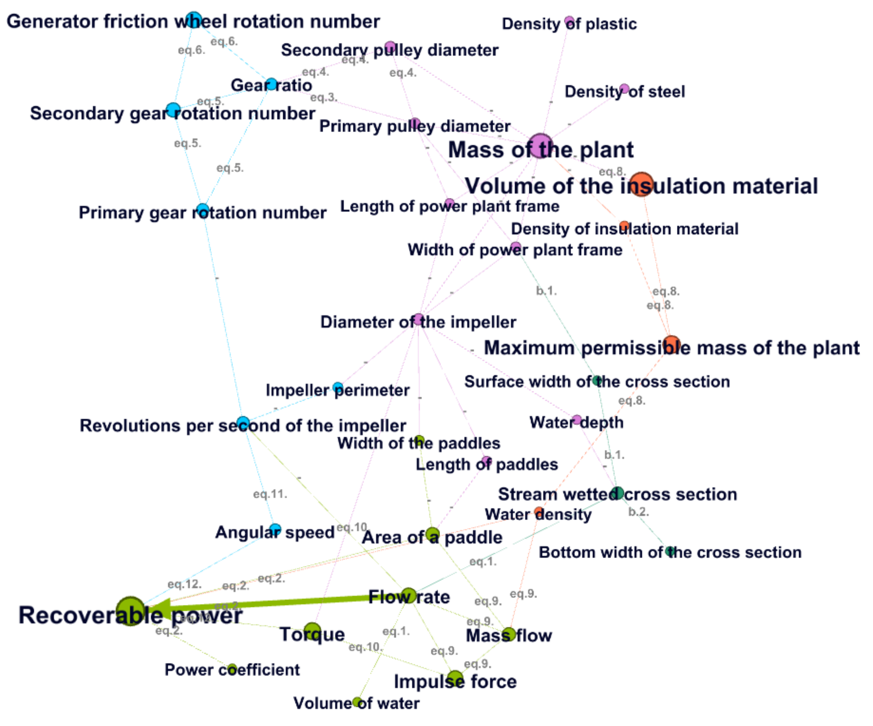
 [Green Version]
Figure 1. The 3D model of the proposed hydropower plant.
Energies 15 06747 g001
Figure 2. The boundary conditions of the water flow.
Energies 15 06747 g002
Figure 3. The design model of the small floating hydropower plant.
Energies 15 06747 g003
Figure 4. The effect of the number of paddles on the performance.
Energies 15 06747 g004
Figure 5. The effects of the pulley tension on the performance.
Energies 15 06747 g005
Figure 6. The network representation of the proposed floating water-wheel-sizing model.
Energies 15 06747 g006
Table 1. The results of the network-based sensitivity analysis.
NodeDescriptionDegreeInDegreeOutDegreePageRankModularity Class
31Recoverable power (P)6600.11754
23Mass of the plant ( m e )10910.09492
24Volume of the insulation material ( V I n s )3120.09093
26Maximum permissible mass of the plant ( m e m a x )3300.05623
30Torque (M)3210.05214
22Generator friction wheel rotation number ( n g )2200.04800
29Impulse force ( F i m p . )3210.04484
4Flow rate (v)6240.04254
21Secondary gear rotation number ( n 2 )3210.03850
14Area of a paddle ( A P )4220.03394
28Mass flow ( m ˙ )4310.03364
16Revolutions per second of the impeller ( n I )4220.02810
3Stream wetted cross section ( A C )4310.02771
20Primary gear rotation number ( n 1 )3210.02730
17Gear ratio (i)6240.02370
27Angular speed ( ω )2110.02220
11Diameter of the impeller ( d I )8350.02172
19Secondary pulley diameter ( d p 2 )4220.02022
18Primary pulley diameter ( d p 1 )5230.01732
9Width of power plant frame ( w F )4130.01462
12Width of the paddles ( w P )2110.01394
13Length of paddles ( l P )2110.01392
15Impeller perimeter ( γ I )2110.01390
5Volume of water (Q)1010.01034
33Power coefficient ( C p )1010.01034
6Water density ( ρ w )3030.01033
25Density of insulation material ( ρ I n s )2020.01033
7Density of steel ( ρ s t e e l )1010.01032
8Density of plastic ( ρ p l a s t i c )1010.01032
10Length of power plant frame ( l F )3030.01032
32Water depth (h)2020.01032
1Surface width of the cross section ( w A s u r f . )2020.01031
2Bottom width of the cross section ( w A b o t t o m )1010.01031
Publisher’s Note: MDPI stays neutral with regard to jurisdictional claims in published maps and institutional affiliations.

