Article

Study on Aerodynamic Characteristics of a Savonius Wind Turbine with a Modified Blade

1
College of Engineering, Northeast Agricultural University, Harbin 150030, China
2
Faculty of Engineering Technology, University of Twente, 7500 Enschede, The Netherlands
*
Author to whom correspondence should be addressed.
Energies 2022, 15(18), 6661; https://doi.org/10.3390/en15186661
Submission received: 30 July 2022 / Revised: 5 September 2022 / Accepted: 8 September 2022 / Published: 12 September 2022

Abstract

:
In order to improve the static start-up problem of Savonius wind turbines, a Savonius wind turbine with a modified blade is proposed. It was obtained by twisting the half-cylindrical blades of the basic Savonius wind turbine by 70°. The aerodynamic performance of the wind turbine before and after the modification was compared. Firstly, the static torque coefficient of two wind turbines at different azimuth angles were obtained by means of three-dimensional numerical simulation. The static flow field around the wind turbine was analyzed. Then, the output power and speed characteristics of a spiral Savonius wind turbine under different incoming wind speeds were evaluated in the wind tunnel. The results show that, compared with the Savonius wind turbine with half-cylindrical blades, the spiral wind turbine could start at any azimuths in one rotation cycle. The reverse torque was eliminated. The static torque coefficient fluctuation range was reduced by 10%. The start-up performance was effectively improved. This investigation could provide guidance for the improvement of start-up characteristics of Savonius wind turbines.

Graphical Abstract

1. Introduction

The rapid development of renewable energy is crucial to deal with the depletion of world fossil fuel stocks. As a clean and renewable energy source, wind energy has been widely used in the world [1]. The wind turbine is the most important equipment for the utilization of wind energy. As a form of rotating machinery, it has the ability to change wind energy into mechanical energy, heat energy and electrical energy [2]. Due to the development of the distributed generation and off-grid generation, small-scale wind turbines have been paid much attention [3]. The vertical axis wind turbine is often selected for small-scale wind energy utilization [4]. According to the working principle, the vertical axis wind turbine is often divided into lift type and drag type [5]. Maalouly investigated the effect of various parameters on the start-up performance of a Darrieus straight-bladed wind turbine. It was found that the chord length of the blade was one of the most important factors that affect the performance of the turbine [6]. The influence of the moment of inertia and blade number on the starting and power behavior of an H-type wind turbine was investigated by Celik [7]. The results showed increasing the number of blades can improve the wind turbine’s starting performance, but it also reduces the power coefficient. In fact, regardless of the type of wind turbine, the blade is the part most widely focused on. Through the reasonable selection of the material and geometry of the wind turbine blade, such as a bionic design for blades enlightened by the structure of owl feathers [8], or the addition of a wind lens to turbines which can generate lower back pressure [9], etc., it is possible to improve effective power and reduce costs [10]. This is because the cost for the entire wind turbine is directly affected by the cost of making one blade [11]. The Savonius wind turbine is a good example, which has a simple construction, full operation moment and a high starting performance [12,13]. However, it still has some shortcomings. The Savonius wind turbine cannot start under some special azimuth angles, nor can it even reverse due to the starting torque being small [14]. There are two main methods to improving these problems. One method entails optimizing the structural parameters of the wind turbine, such as twisting Savonius blades [15] and improving the alignment of Savonius blades [16]. The second entails adding an auxiliary structure, such as adding a deflector, wind hood, and so on. Recently, scholars have tried to incorporate artificial intelligence into the Savonius wind turbine optimization method to guarantee higher efficiency and commercial viability [17]. In this study, the first method is used to improve the starting performance of the Savonius wind turbine.
To optimize the start-up performance of the Savonius wind turbine, Tian et al. adjusted the Savonius rotor with different convex and concave sides. A particle swarm optimization (PSO) algorithm was selected to improve power efficiency. The results showed that the tip vortices and recovery flows of the blade improved significantly [18]. Kerikous et al. proposed a shape in which the concave and convex sides evolved independently of each other. The optimal alignment and thickness parameters were obtained by transient computational fluid dynamic simulations and a wind tunnel experiment [19]. Alom proposed elliptical linear blades. The results showed that the start-up performance of elliptical linear blades was better than that of circular linear blades [20]. Wang put forward an impeller scheme with different bilateral contour: the power generation of the improved wind turbine increased by 7.17% [21]. Pan et al. proposed the model of a spiral-blade Savonius wind turbine [22]. Numerical simulation was carried out in the case of the obtuse torsion angle. The law of interaction between blades was obtained. On this basis, Zhu et al. carried out theoretical analyses and wind tunnel tests on a spiral Savonius wind turbine with a torsion angle of 180° [23]. The wind energy utilization coefficient of spiral and traditional Savonius wind turbines was analyzed. The results indicated that the power coefficient was improved significantly by high aspect ratios of the wind turbine and end plates.
Based on the analysis of the above research, it can be found that the start-up performance of the spiral wind turbine formed by torsion of the basic type, that is, the Savonius wind turbine with half-cylindrical blades, can be improved to some extent. This study continues to carry out in-depth research regarding this research idea. At present, scholars have studied the spiral wind turbine with an obtuse torsion angle. However, the starting characteristic of the wind turbine with an acute angle torsion is not clear.
In this study, the spiral Savonius wind turbine with a torsion angle of 70° was chosen as an example. The static torque coefficient of basic Savonius wind turbines and spiral Savonius wind turbines were compared by means of three-dimensional numerical simulation and a wind tunnel experiment. The purpose of this paper is to provide a reference for the research regarding the development of the start-up performance of Savonius wind turbines.

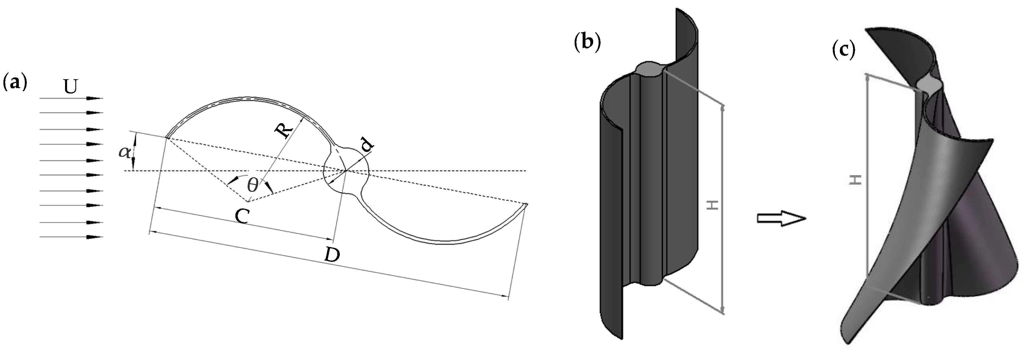
2. Wind Turbine Model

Figure 1 shows the schematic diagram of the basic Savonius wind turbine with half-cylindrical blades and the Savonius wind turbine model with a 70° torsion angle blades proposed in this study. The basic type was composed of two half-cylindrical blades, which were connected by a rotating shaft. The spiral wind turbine was obtained by turning the basic blade 70° clockwise. The main structural parameters of the two wind turbine models are presented in Table 1. The azimuth angle of 0° was defined as the point in which the connection of blade vertices is parallel to the incoming wind. The clockwise direction was selected as the positive direction.

2.1. Performance Parameter

The aerodynamic performance parameters of the wind turbine included the static torque coefficient, power coefficient and tip speed ratio of wind turbine. The static torque coefficient was utilized to evaluate the starting performance of the wind turbine [24]. It was obtained by Equation (1):
C T s = T s 1 2 ρ A U 2 R
The power coefficient can be calculated by the ratio of power output from the rotor to the power input, as shown in Equation (2):
C P = P 1 2 ρ A U 3
The tip speed ratio, which is often used to characterize rotational state, is the ratio of the rotational speed of the blade tip to the wind speed [25]. It was defined as Equation (3):
λ = V U = ω R U
In the equation, CTs is the torque acting on the Savonius turbine, N·m; ρ is the air density, kg/m3; A is the wind turbine swept area, m2; U is the incoming wind speed, m/s; R is the wind turbine blade radius, m; V is the wind turbine outer diameter tangent speed, m/s; ω is the wind turbine rotation angular speed, rad/s; P is the wind turbine power, W.

2.2. Numerical Simulation

2.2.1. Turbulence Model

Numerical simulations were carried out to investigate the performance of the modified spiral Savonius wind turbine. The three-dimensional mesh of the turbine model was created by ICEM. Then, the computational model was iteratively calculated in ANSYS FLUENT. In this paper, the RNG k-ε turbulence model was selected for numerical simulation. The transport and turbulent viscosity equation of the turbulence model is shown in Equations (4)–(6). The SIMPLE algorithm was used for pressure–velocity coupling. The second-order upwind model was used to calculate the momentum, turbulence momentum and dissipation rate.
( ρ k ) t + ( ρ k u i ) t x i = x j α k μ e f f k x j + G k + G b ρ ε Y M
( ρ ε ) t + ( ρ ε u i ) x i = x j α ε μ e f f ε x j + C 1 ε ε k ( G k + C 3 ε G b ) G 2 ε ρ ε 2 k R ε
μ e f f = ρ C μ k 2 ε
where Gk is the turbulence kinetic energy generated by the mean velocity gradients; Gb is the turbulence kinetic energy generated by buoyancy; YM is the contribution of the fluctuating dilatation in compressible turbulence to the overall dissipation rate; ρ is the air density; k is the turbulent kinetic energy; ε is the turbulent dissipation rate; μeff is the coefficient of turbulent viscosity. The values of αk and αε are the Prandtl number of the k equation and ε equation, respectively. C = 1.42, C = 1.68 and Cμ = 0.0845.

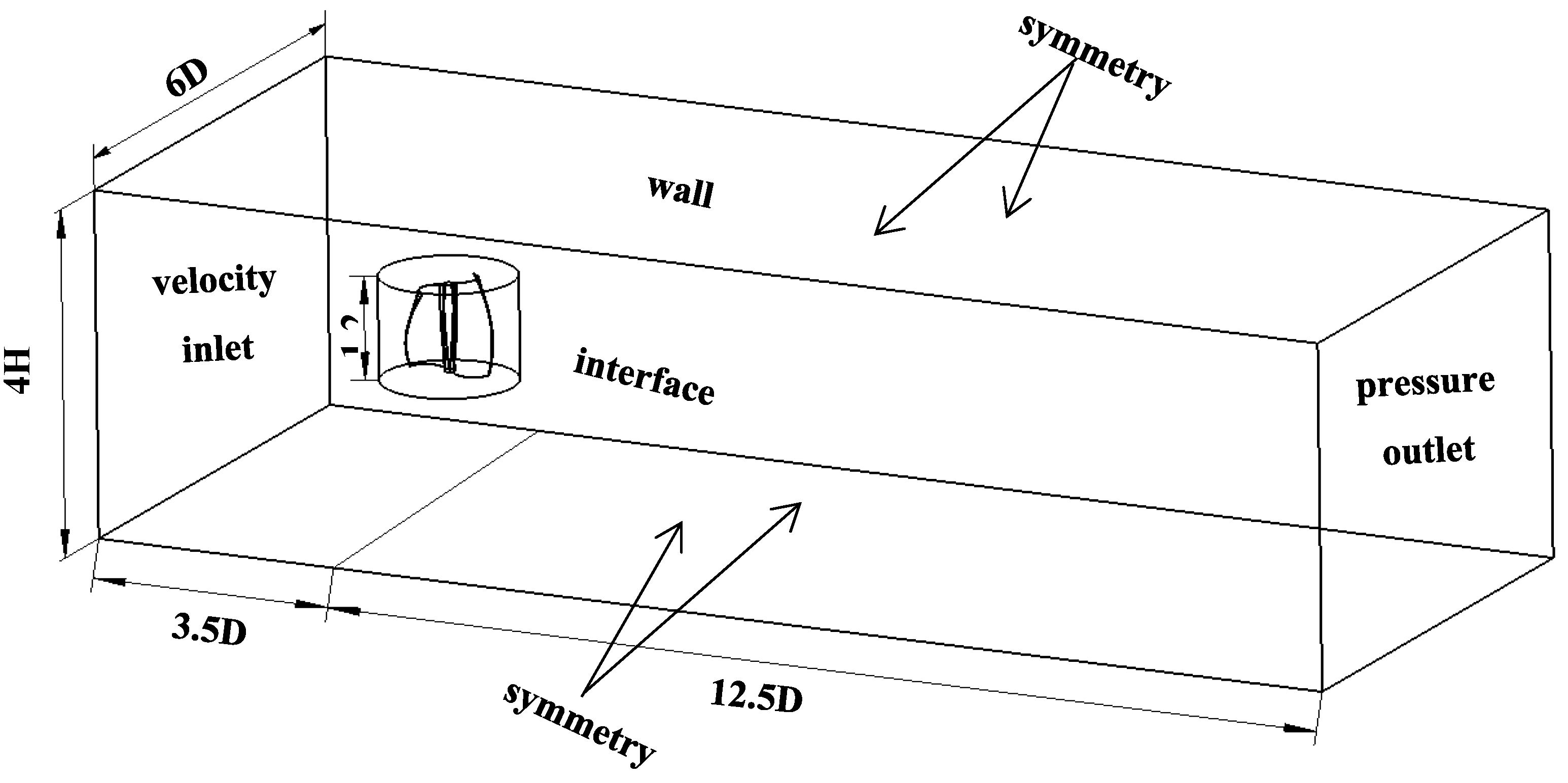
2.2.2. Establishment of Computational Domain

In this paper, the calculation domain adopted the combination of the rotational and static domain to refine the grid. As shown in Figure 2, D is the rotating diameter of the spiral blade and H is the height of the spiral blade. The diameter and height of the rotational domain were 1.6D and 1.2H, respectively. The measurements of the static domain were 16D, 6D and 4H, respectively. The rotational region was the main working area of the blade. The blade surface was set as a non-slip wall. The interface was the sliding grid, which was widely set to the rotational rotor, without leading to grid deformation. In the static domain, the velocity inlet with the wind speed was the inlet. The pressure outlet with atmospheric pressure was the outlet. The other surface was the no-slip wall. The mesh size of the interface of the static domain and the rotational domain were the same to ensure the continuity of the mesh interface.

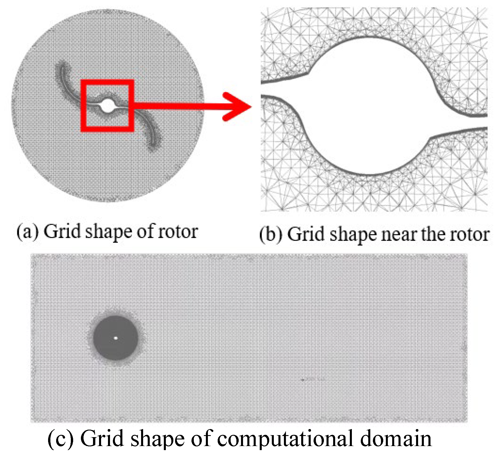
2.2.3. Grid Division

In the process of numerical simulation, the geometry was divided by a tetrahedral mesh due as it has a high accuracy for the simulation of wind turbine. The grid of the blade in the rotational domain was encrypted. The thickness of the boundary layer near the blade was set to 10 layers. The radial growth rate of the grid was 1.25. The thickness of the first layer grid was set as 0.014 mm to ensure that the maximum value of y+ was less than 1. Figure 3 shows the details of the structured mesh.

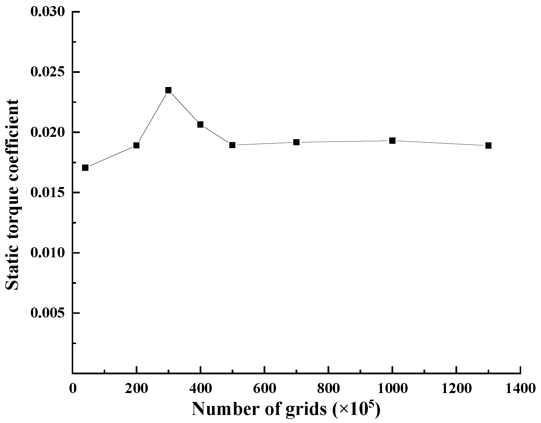
2.2.4. Grid and Time Step Independence Verification

Different mesh sizes were selected to guarantee the grid independence and avoid prohibitive computational consumption. The best grid size was obtained by comparing the changes of the static torque coefficient with various grid numbers. As shown in Figure 4, the wind turbine with an azimuth angle of 0° was chosen as an example. When the grid number was more than five million, the static torque coefficient of the blade tended to be stable. Considering the calculation time cost, 5,155,826 was chosen as the number of grids in the investigation.
Time independence is also a very crucial factor that needs to be evaluated. In this paper, the static torque coefficient was set as the index. Three various time steps were simulated, which were ∆t = 9.35 × 10⁻⁴ s, ∆t = 1.89 × 10⁻³ s and ∆t = 5.61 × 10⁻³ s, respectively. The results for the three simulations are shown in Figure 5. Observing the static torque coefficient for the time steps of 9.35 × 10⁻⁴ s and 1.89 × 10⁻³ s, it is obvious that they were almost identical. Hence, ∆t = 1.89 × 10⁻³ s was selected as the time step during numerical simulation.

2.2.5. Comparison between Wind Tunnel Test and Numerical Simulation

To ensure the reliability of the simulation results, the static torque coefficient of the spiral Savonius wind turbine under an azimuth angle of 0°~180° obtained by numerical simulation was compared with the experiment results. As shown in Figure 6, the simulation results were basically consistent with the experimental results. In order to compare the differences between the simulation and experimental results, an analysis of variance was conducted, as presented in Table 2. The ANOVA results indicated that there was no significantly statistical difference between the experimental and simulation results (p > 0.01). Therefore, it was considered feasible to use the simulation results. The maximum static torque coefficient was obtained when the azimuth was 50°. The experimental and simulated values were 0.31 and 0.35, respectively. The numerical simulation results were higher than the experimental results. This was because the experimental environment was more complex than the computational environment. There was energy loss caused by friction during the working of wind turbine, which made the actual torque of the wind turbine relatively small.

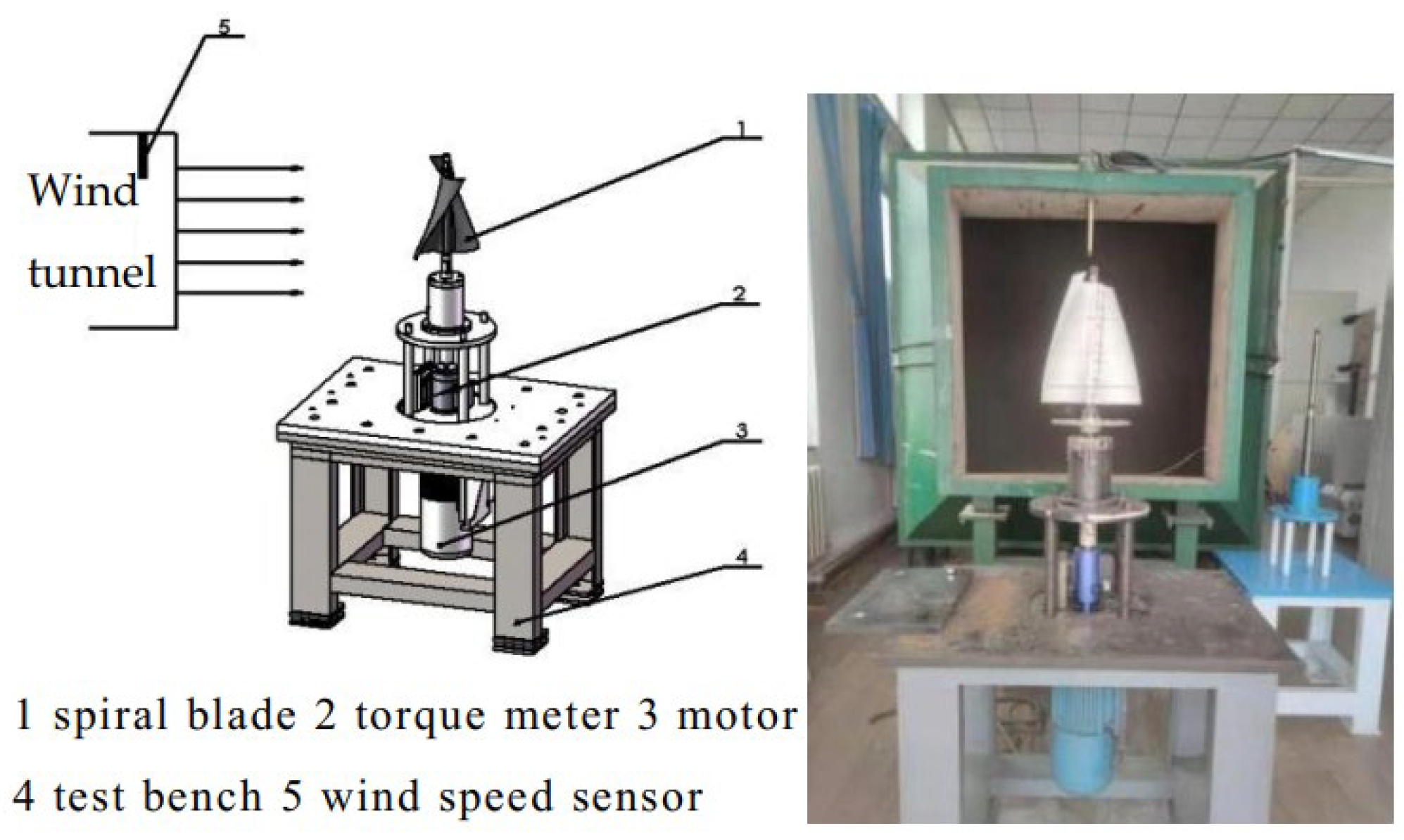
2.3. Wind Tunnel Test

In this paper, the wind tunnel experiment was conducted. The power coefficient and rotational speed of the improved spiral Savonius wind turbine were tested under different incoming wind speeds of 6 m/s, 8 m/s, 10 m/s and 12 m/s with a tip speed ratio of 0.1 to 0.6.
The structure schematic diagram of the spiral Savonius wind turbine in this study is shown in Figure 7. It was mainly composed of the spiral blade, torque meter, motor, test bench and wind speed sensor. The test was conducted in a low-speed open-type wind tunnel in the wind energy laboratory of Northeast Agricultural University. The wind tunnel had a length of 9.1 m and a width of 2.3 m, and the area of the experimental section was 1 m × 1 m. The range of wind speed was 1 m/s~20 m/s with an accuracy of 3%. The non-uniformity of air flow was less than 0.5%. The degree of turbulence was less than 0.5%. The deviation angle of air flow was less than 0.5°.
The wind turbine model was fixed at the center of the wind tunnel outlet and at a distance of 1 m from the outlet [26]. During the experiment, the ultrasonic wind sensor was used to measure the wind speed with an accuracy of ±0.1%. The digital torque was used to measure the torque of the rotor with an accuracy of ±0.2% under 1 ms of the sampling time. The measuring range was 5 N·m.

3. Results and Analysis

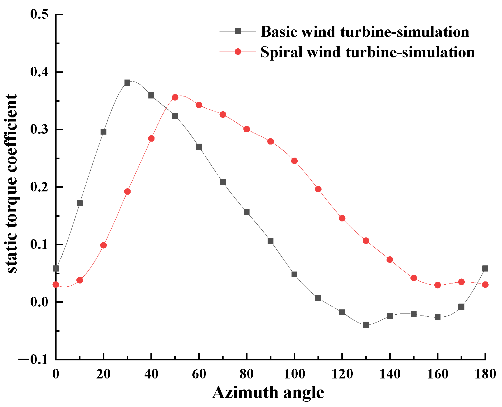
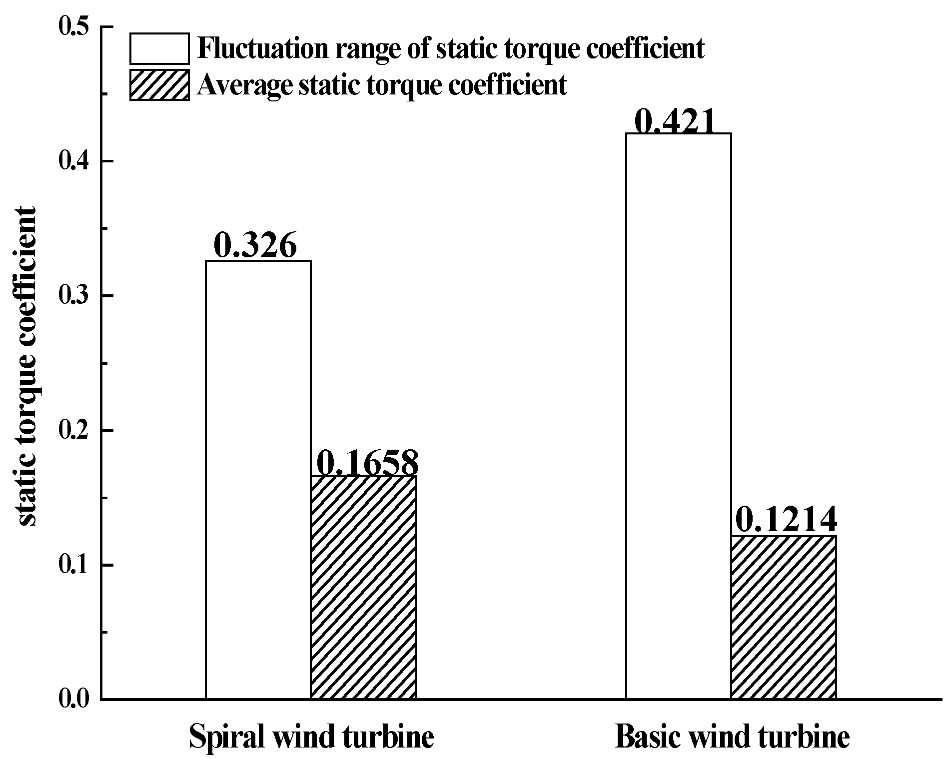
3.1. Static Starting Characteristic

To compare the starting capability of the basic Savonius wind turbine and the spiral Savonius wind turbine, numerical simulation was carried out. Under the conditions of a wind speed of 12 m/s and a rotational azimuth of 0°~180° with an interval of 10°, the static torque coefficient, fluctuation range and average value were obtained. The results are shown in Figure 8 and Figure 9.
As shown in Figure 8, the static torque coefficient of the basic and spiral wind turbine increased at first, and then decreased as the azimuth angle increased. The static torque coefficient of the basic Savonius wind turbine was negative with an azimuth of 120°~170°, which meant the wind turbine could not be started; meanwhile, the spiral Savonius wind turbine could start at any azimuth angle. This means that the starting performance of the Savonius wind turbine could be enhanced if the azimuth range is expanded.
When the azimuth angle was 0°~40°, the static torque coefficient of the spiral Savonius wind turbine was smaller than that of the basic Savonius wind turbine. This was because the energy obtained by the lower part of the spiral blade was smaller than that of the upper part of the blade, so the static torque coefficient was smaller. The basic Savonius wind turbine had no distortion angle, so there was no decrease in energy captured by the lower part of the blade. When the azimuth was larger than 50°, the static torque coefficient of the spiral Savonius wind turbine was larger than that of the basic Savonius wind turbine, which means the starting characteristic of 72.2% of the azimuth angle was improved. For the twisted blade, the maximum force moved to the tip of the blade, resulting in a longer arm. As a result, the static torque coefficient was generally larger than that of the basic Savonius wind turbine.
As shown in Figure 9, the static torque coefficient fluctuation of the spiral Savonius wind turbine was smaller than that of the basic Savonius wind turbine. The static torque coefficient range was reduced by 22.6%, indicating that the Savonius wind turbine had better stability. At the same time, Figure 9 shows that the average static torque coefficient of the spiral Savonius wind turbine was larger than that of the basic Savonius wind turbine. The average static torque coefficient increased by 36.6%.

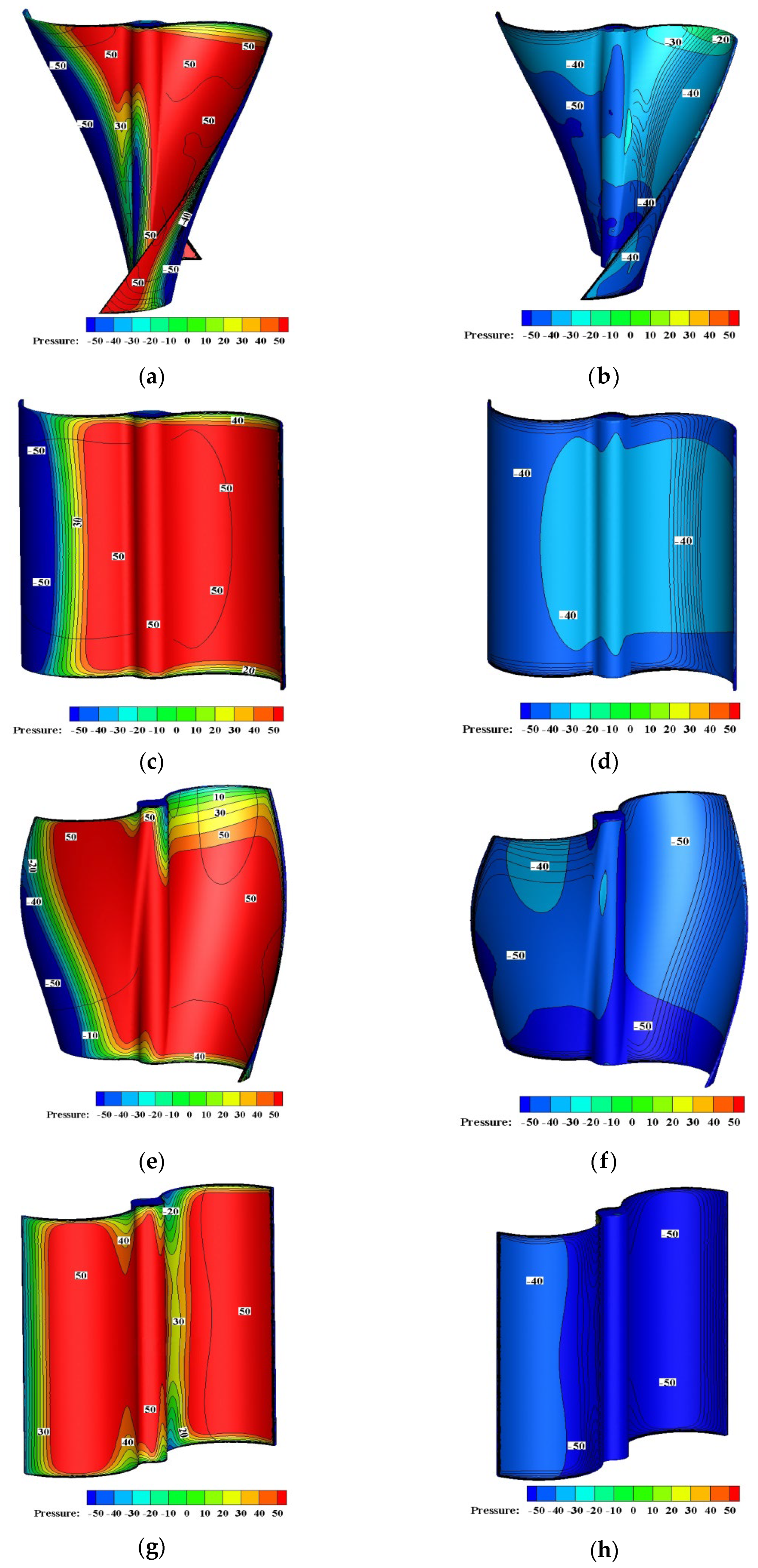
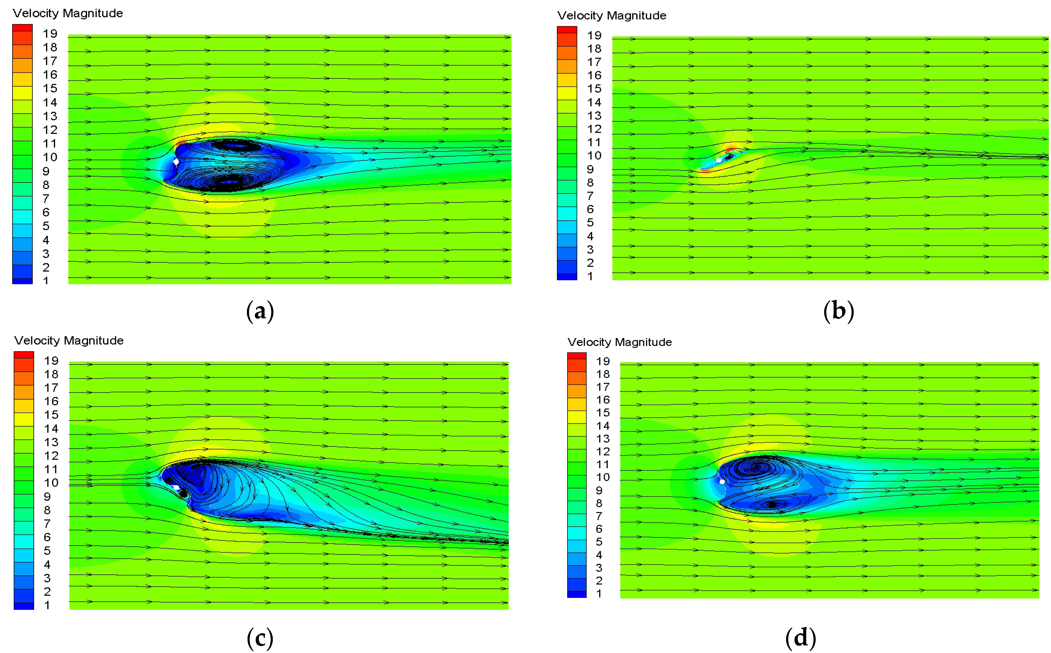
3.2. Static Flow Field

The changes of the flow field around the spiral Savonius wind turbine and the basic Savonius wind turbine were compared to further analyze the performance of the improved Savonius turbine. The pressure and velocity distributions were obtained to analyze flow field characteristics under two typical wind turbine rotation azimuths, namely 60° and 120°, as shown in Figure 10 and Figure 11. Figure 10a–d show the pressure distribution with an azimuth of 60°, and Figure 10e–h show the pressure distribution with an azimuth of 120°.
As shown in Figure 10a–d, from the windward point of view, the pressure of the thrust blade of the spiral Savonius wind turbine was similar to that of the basic Savonius wind turbine. However, the pressure of the resistance blade of the spiral Savonius wind turbine was lower than that of the basic Savonius wind turbine. From the leeward point of view, the pressure of the spiral Savonius wind turbine and the basic Savonius wind turbine were both negative, but the pressure of the thrust surface of the spiral Savonius wind turbine was higher than that of the basic Savonius wind turbine. Meanwhile, the pressure of the resistance surface was lower than that of the basic Savonius wind turbine. For the whole blade, the pressure difference in the thrust blade of the spiral Savonius wind turbine was larger than that of the basic Savonius wind turbine. Meanwhile, the pressure difference in the resistance blade of the spiral Savonius wind turbine was smaller than that of the basic Savonius wind turbine. Therefore, the static torque of the spiral Savonius wind turbine was larger than that of the basic Savonius wind turbine when the azimuth was 60°.
As shown in Figure 10e–h, it was consistent with the analysis results of the azimuth was 60°. While the difference was that when the azimuth was 120°, the pressure difference of the thrust blade of the basic Savonius wind turbine was smaller than that of the resistance blade, causing the wind turbine could not start.
In Figure 11a,b, the velocity distribution with an azimuth of 60° is shown, and the velocity distribution with an azimuth of 120° is shown in Figure 10c,d. As shown in Figure 11a–d, the convex surface velocities of the upper and lower blades of the spiral Savonius wind turbine with an azimuth of 60° were about 18 m/s. Meanwhile, there were no vortices. Thus, there was little energy loss. In contrast, the basic Savonius wind turbine produced two large vortices behind, which obviously affected the speed of the wind turbine, but it still could rotate. When the azimuth was 120°, both the basic Savonius wind turbine and the spiral Savonius wind turbine produced vortices behind. However, the two concave surfaces of the basic Savonius wind turbine also produced vortices, so the obtained energy was low, and the wind turbine could not start.

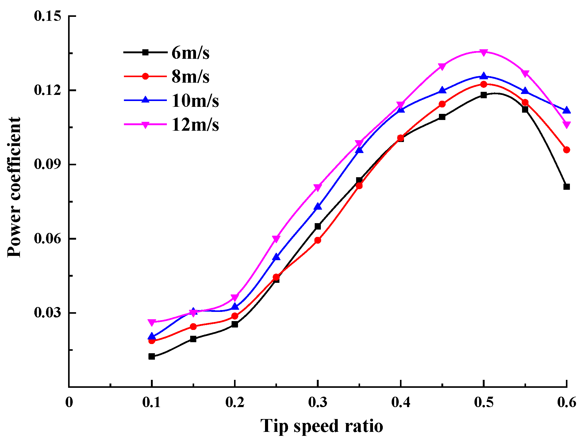
3.3. Power Characteristic

The output power coefficients with a different tip speed ratio were compared to explore the output performance of the spiral Savonius wind turbine under various wind speeds. As shown in Figure 12, under different incoming wind speeds, the power coefficient of the spiral Savonius wind turbine increased at first, before decreasing with the increase in the tip speed ratio. This was because the wind speed was constant during the initial start-up stage of the wind turbine, and the lift increased with the increase in the tip speed ratio, so the power coefficient increased. When the optimum tip speed ratio was exceeded, the rotational speed continually increased and the dynamic stall phenomenon occurred; that is, the wind turbine was driven by the motor. As a result, the power coefficient decreased. When the incoming wind speed was 12 m/s and the tip speed ratio was 0.5, the optimal power coefficient was 0.136.

3.4. Rotational Speed Characteristic

The rotational speed of the spiral Savonius wind turbine was measured under various wind speeds. As shown in Figure 13, the wind turbine could start to rotate at any wind speed. In addition, with the increase in incoming wind speed, the instantaneous rotational speed of the spiral Savonius wind turbine also increased. At any wind speed, the instantaneous rotational speed increased to a certain range in an instant, which means it had a better starting characteristic. The fluctuation range was small. The wind turbine run stably, due to the fact that the upwind area of the spiral Savonius wind turbine was almost the same at any azimuth angle. However, there were still some fluctuations in rotational speed of the spiral Savonius wind turbine. This was because the spiral Savonius wind turbine moved axially during the working process. With the change in azimuth, there was a certain loss in tip flow near the top or bottom of the wind turbine, thus causing fluctuations.

4. Conclusions

In this study, the blade of the basic Savonius wind turbine was modified. The spiral Savonius wind turbine with a twist angle of 70° was designed. The influence of the starting characteristics and aerodynamic characteristics were investigated by the combination of numerical simulation and a wind tunnel experiment. The main conclusions are as follows:
(1)
The basic Savonius wind turbine could not start between an azimuth of 120° and 170°, while the spiral Savonius wind turbine could start between an azimuth of 0° and 180°. The static torque coefficient of the improved wind turbine was 72.2% higher.
(2)
Compared with the basic Savonius wind turbine, the stability and efficiency of the spiral Savonius wind turbine was improved. The average torque coefficient was increased by 36.6%.
(3)
Through the analysis of flow field characteristics, the velocity flow field and pressure of the spiral Savonius wind turbine were better than that of the basic Savonius wind turbine.
(4)
Through the wind tunnel test, the static torque coefficient of the spiral Savonius wind turbine under 12 m/s, the power coefficient and instantaneous rotational speed under different wind speeds were obtained. When the azimuth was 50°, the maximum static torque coefficient was 0.31. When the wind speed was 12 m/s and the tip speed ratio was 0.5, the maximum power coefficient was 0.136.

Author Contributions

Conceptualization, Z.M., Z.X., F.F. and Y.L.; Formal analysis, Z.M.; Funding acquisition, F.F.; Investigation, Z.M.; Methodology, Z.M., Z.X. and Y.L.; Software, G.T.; Supervision, F.F.; Validation, G.T.; Visualization, Q.D. and G.V.A.; Writing—original draft, Z.M.; Writing—review & editing, Z.M., Q.D., F.F., Y.L. and G.V.A. All authors have read and agreed to the published version of the manuscript.

Funding

This research was funded by the ‘Academic Backbone’ Project of Northeast Agricultural University (20XG20) and the HeiLongjiang Postdoctoral Fund (LBH-Z20038).

Institutional Review Board Statement

Not applicable.

Informed Consent Statement

Not applicable.

Data Availability Statement

Not applicable.

Conflicts of Interest

The authors declare no conflict of interest.

Nomenclature

CPOutput power coefficient,
CTsStatic torque coefficient,
λTip speed ratio,
TsTorque acting on Savonius turbine, N·m
ρAir density, kg/m3
AWind turbine swept area, m2
UIncoming wind speed, m/s
RWind turbine radius, m
VWind turbine outer diameter tangent speed, m/s
ωWind turbine rotation angular speed, rad/s
PWind turbine power, W
CChord length, m
DRotor diameter, m
RBlade radius, m
TBlade thickness, m
HBlade height, m
dClearance between two blades, m
θArc angle, °
αAzimuth angle of rotor against wind, °

References

  1. Amjith, L.; Bavanish, B. A review on biomass and wind as renewable energy for sustainable environment. Chemosphere 2022, 293, 133579. [Google Scholar] [CrossRef]
  2. Zhang, L.; Li, Y.; Zhang, H.; Xu, X.; Yang, Z.; Xu, W. A review of the potential of district heating system in Northern China. Appl. Therm. Eng. 2021, 188, 116605. [Google Scholar] [CrossRef]
  3. Tummala, A.; Velamati, R.K.; Sinha, D.K.; Indraja, V.; Krishna, V.H. A review on small scale wind turbines. Renew. Sustain. Energy Rev. 2016, 56, 1351–1371. [Google Scholar] [CrossRef]
  4. Li, Y.; Zhao, S.; Tagawa, K.; Feng, F. Starting performance effect of a truncated-cone-shaped wind gathering device on small-scale straight-bladed vertical axis wind turbine. Energy Convers. Manag. 2018, 167, 70–80. [Google Scholar] [CrossRef]
  5. Xu, Y.; Sun, X. Review on the application of variable-pitch to performance improvement of the lift-type vertical axis wind turbine. Renew. Resour. Res. 2020, 36, 194–200. [Google Scholar]
  6. Maalouly, M.; Souaiby, M.; ElCheikh, A.; Issa, J.; Elkhoury, M. Transient analysis of H-type Vertical Axis Wind Turbines using CFD. Energy Rep. 2022, 8, 4570–4588. [Google Scholar] [CrossRef]
  7. Celik, Y.; Ma, L.; Ingham, D.; Pourkashanian, M. Aerodynamic investigation of the start-up process of H-type vertical axis wind turbines using CFD. J. Wind Eng. Ind. Aerodyn. 2020, 204, 104252. [Google Scholar] [CrossRef]
  8. Gao, R.; Chen, K.; Li, Y.; Yao, W. Investigation on aerodynamic performance of wind turbine blades coupled with airfoil and herringbone groove structure. J. Renew. Sustain. Energy 2021, 13, 053301. [Google Scholar] [CrossRef]
  9. Khamlaj, T.A.; Rumpfkeil, M.P. Analysis and optimization of ducted wind turbines. Energy 2018, 162, 1234–1252. [Google Scholar] [CrossRef]
  10. Kang, C.; Liu, H.; Yang, X. Review of fluid dynamics aspects of Savonius-rotor-based vertical-axis wind rotors. Renew. Sustain. Energy Rev. 2014, 33, 499–508. [Google Scholar] [CrossRef]
  11. Jureczko, M.; Mrówka, M. Multiobjective Optimization of Composite Wind Turbine Blade. Materials 2022, 15, 4649. [Google Scholar] [CrossRef] [PubMed]
  12. Yao, J.; Li, F.; Chen, J.; Su, Z.; Yu, J. Development status of vertical axis resistance Type Savonius turbine. J. Harbin Eng. Univ. 2020, 41, 298–308. [Google Scholar]
  13. Akwa, J.V.; Vielmo, H.A.; Petry, A.P. A review on the performance of Savonius wind turbines. Renew. Sustain. Energy Rev. 2012, 16, 3054–3064. [Google Scholar] [CrossRef]
  14. Kim, K.C.; Ji, H.S.; Kim, Y.K.; Lu, Q.; Baek, J.H.; Mieremet, R. Experimental and numerical study of the aerodynamic characteristics of an archimedes spiral wind turbine blade. Energies 2014, 7, 7893–7914. [Google Scholar] [CrossRef]
  15. Lee, J.-H.; Lee, Y.-T.; Lim, H.-C. Effect of twist angle on the performance of Savonius wind turbine. Renew. Energy 2016, 89, 231–244. [Google Scholar] [CrossRef]
  16. Cuevas-Carvajal, N.; Cortes-Ramirez, J.; Norato, J.A.; Hernandez, C.; Montoya-Vallejo, M. Effect of geometrical parameters on the performance of conventional Savonius VAWT: A review. Renew. Sustain. Energy Rev. 2022, 161, 112314. [Google Scholar] [CrossRef]
  17. Al Noman, A.; Tasneem, Z.; Sahed, M.F.; Muyeen, S.M.; Das, S.K.; Alam, F. Towards next generation Savonius wind turbine: Artificial intelligence in blade design trends and framework. Renew. Sustain. Energy Rev. 2022, 168, 112531. [Google Scholar] [CrossRef]
  18. Tian, W.; Mao, Z.; Zhang, B.; Li, Y. Shape optimization of a Savonius wind rotor with different convex and concave sides. Renew. Energy 2018, 117, 287–299. [Google Scholar] [CrossRef]
  19. Kerikous, E.; Thévenin, D. Optimal shape of thick blades for a hydraulic Savonius turbine. Renew. Energy 2018, 134, 629–638. [Google Scholar] [CrossRef]
  20. Alom, N. Influence of curtain plates on the aerodynamic performance of an elliptical bladed Savonius rotor (S-rotor). Energy Syst. 2021, 13, 265–280. [Google Scholar] [CrossRef]
  21. Wang, W.; Song, B.W.; Mao, Z.Y.; Tian, W. Optimization of Savonius wind turbine impeller with bilateral contour. J. Harbin Eng. Univ. 2019, 40, 254–259+272. [Google Scholar]
  22. Pan, C.; Kang, C.; Zhang, W. Numerical investigation of combination and interfence of vertical-axis spiral wind impeller. Acta Energ. Sol. Sin. 2018, 39, 2118–2124. [Google Scholar]
  23. Zhu, J.; Liu, P. Experimental study on aerodynamic characteristics of helical Savonius rotor with twist of 180°. J. Mech. Eng. 2020, 56, 155–161. [Google Scholar]
  24. Li, Y.; Zhao, S.; Qu, C.; Tong, G.; Feng, F.; Zhao, B.; Kotaro, T. Aerodynamic characteristics of Straight-bladed Vertical Axis Wind Turbine with a curved-outline wind gathering device. Energy Convers. Manag. 2019, 203, 112249. [Google Scholar] [CrossRef]
  25. Guo, W.; Shen, H.; Li, Y.; Feng, F.; Tagawa, K. Wind tunnel tests of the rime icing characteristics of a straight-bladed vertical axis wind turbine. Renew. Energy 2021, 179, 116–132. [Google Scholar] [CrossRef]
  26. Feng, F. Research on Aerodynamic Characteristics of Combined Vertical Axis Wind Turbine with Lift Drag Combined Starting Structure. Ph.D. Thesis, Northeast Agricultural University, Harbin, China, 2018. [Google Scholar]
Figure 1. Schematic diagram of wind turbine model. (a) schematic diagram of basic type and spiral profile. (b) basic 3D graph. (c) spiral 3D graph.
Energies 15 06661 g001
Figure 2. Computational domain of numerical simulation.
Energies 15 06661 g002
Figure 3. Local grid.
Energies 15 06661 g003
Figure 4. Static torque coefficient of spiral Savonius wind turbine in different grid numbers (α = 0°).
Energies 15 06661 g004
Figure 5. Time independence results.
Energies 15 06661 g005
Figure 6. Comparison of the experiment with the numerical results.
Energies 15 06661 g006
Figure 7. Structure diagram of spiral wind turbine test.
Energies 15 06661 g007
Figure 8. Static torque coefficient of basic and spiral wind turbines.
Energies 15 06661 g008
Figure 9. The range and average of static torque coefficient.
Energies 15 06661 g009
Figure 10. Pressure and streamlines nephograms of wind turbine. (a) upwind side of spiral wind turbine with azimuth of 60°. (b) leeward side of spiral wind turbine with azimuth of 60°. (c) upwind side of basic wind turbine with azimuth of 60°. (d) leeward side of basic wind turbine with azimuth of 60°. (e) upwind side of spiral wind turbine with azimuth of 120°. (f) leeward side of spiral wind turbine with azimuth of 120°. (g) upwind side of basic wind turbine with azimuth of 120°. (h) leeward side of basic wind turbine with azimuth of 120°.
Energies 15 06661 g010
Figure 11. Velocity and streamlines nephograms of wind turbine. (a) 60° basic wind turbine (Z = 0). (b) 60° spiral wind turbine (Z = 0). (c) 120° basic wind turbine (Z = 0). (d) 120° spiral wind turbine (Z = 0).
Energies 15 06661 g011
Figure 12. Output power coefficients of spiral wind turbine under various incoming wind speeds.
Energies 15 06661 g012
Figure 13. Rotating characteristics of spiral wind turbine under various incoming wind speeds.
Energies 15 06661 g013
Table 1. Model parameters.
ParametersValue
Blade airfoilSpiral blade
Blade number2
Chord length (C) [m]0.112
Rotational diameter (D) [m]0.224
Blade height (H) [m]0.252
Blade radius (R) [m]
Blade thickness (T) [m]
0.1
0.002
Clearance between two blades (d) [m]0.024
Arc angle (θ) [°]125
Table 2. ANOVA results of simulation and experiment.
Origin of VarianceSum of SquaresdfMean SquaresF Valuep Value
Different groups0.0038110.003810.27880.60092
Interior group0.46431340.01366
Total0.4681235
* Extremely significant at p < 0.01.
Publisher’s Note: MDPI stays neutral with regard to jurisdictional claims in published maps and institutional affiliations.

