
The Standard Geothermal Plant as an Innovative Combined Renewable Energy Resources System: The Case from South Poland

 ,
,  ,
,
Abstract
:1. Introduction
- -
- Increasing the products/services offered by the company;
- -
- Ensuring more energy independence for the facility by diversifying the energy sources and increasing the share of those based on RES;
- -
- Implementing a sustainable development strategy for the protection of the environment and to make a contribution to climate protection.
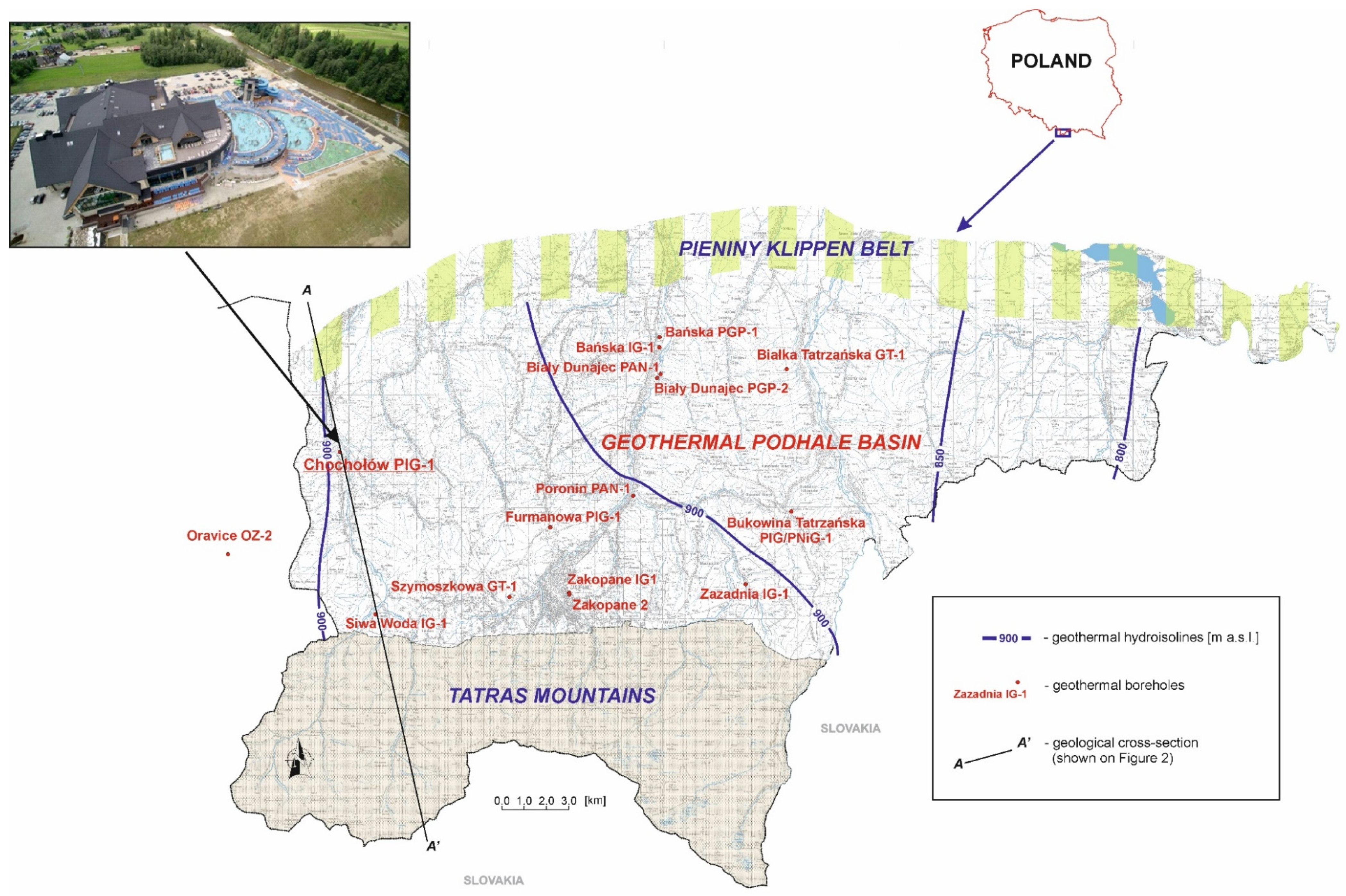
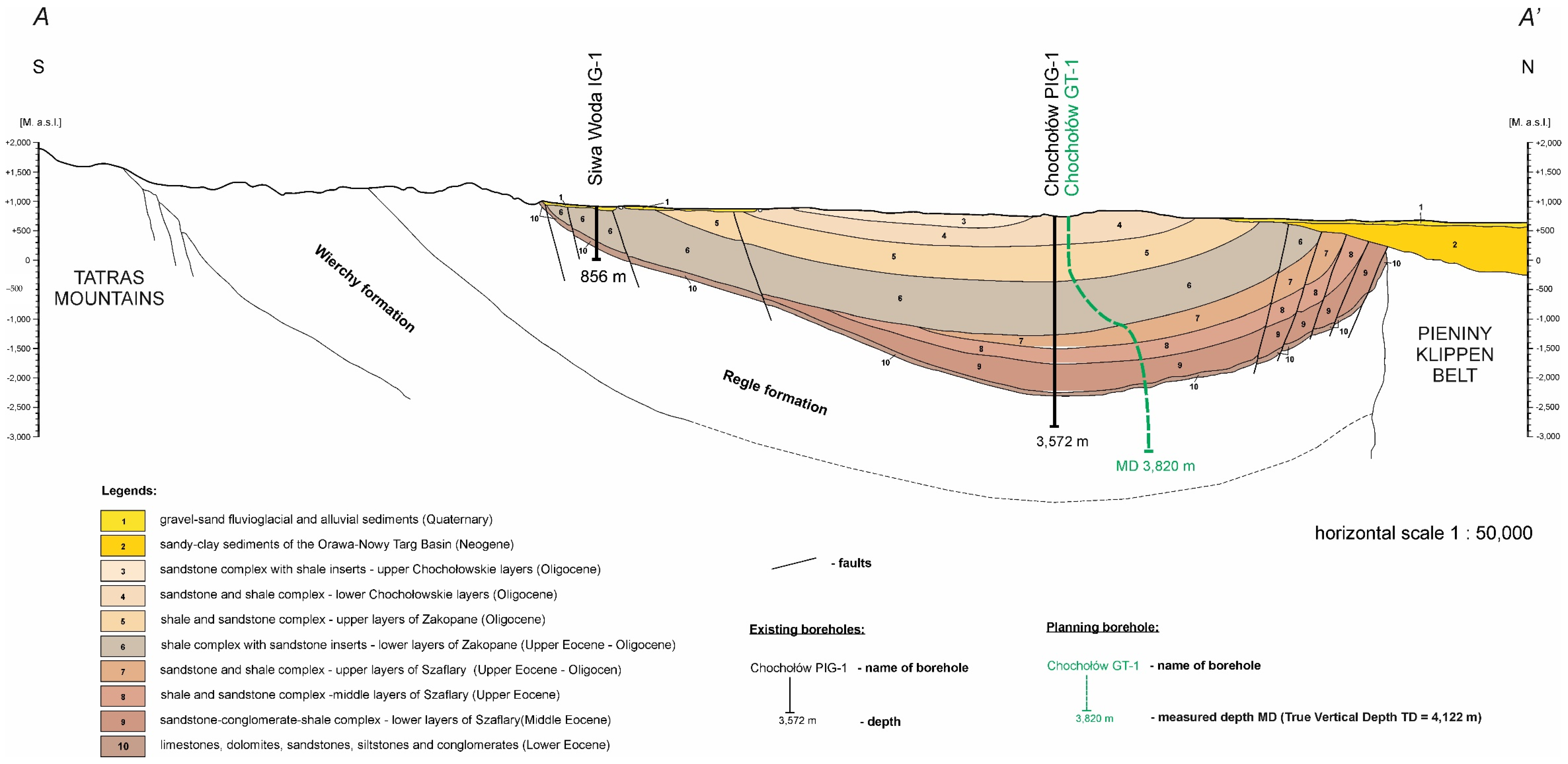
2. Case Study: Chochołowskie Termy Geothermal Complex
Geothermal Borehole Duplex
3. Case Study (Methodology and Aim of Combined RES System)
3.1. Heat and Electricity Demand
- -
- Due to the lack of separation of heat streams between the central heating systems of radiators and underfloor heating, the analyses assumed that the entire power associated with the central heating system is disbursed for radiator technology (70/50 °C in existing facilities and 50/35 °C in new facilities).
- -
- Similarly for mechanical ventilation, where it is assumed that the small heat flux for air curtains is included in the mechanical ventilation flux of 70/50 °C, as in the existing facilities (in favor of certainty). In the newly constructed facilities, 60/40 °C has been assumed for ventilation.
- -
- Hot water heating up to 60 °C was assumed (in order to ensure the required 55 °C in water intakes, assuming possible transmission losses).
- -
- The temperature was assumed to be raised by 2 K in the pool exchangers responsible for maintaining the water temperature during the normal operation of the facility.
- -
- A water temperature of 10 °C was assumed in the water supply system.
- -
- The following parameters for the geothermal water extracted from the planned Chochołów GT-1 borehole were assumed for the analysis:
- Temperature 88 °C;
- Pressure 160 kPa;
- Flow capacity 160 m3/h (equivalent to a mass flow of 44.44 kg/s).
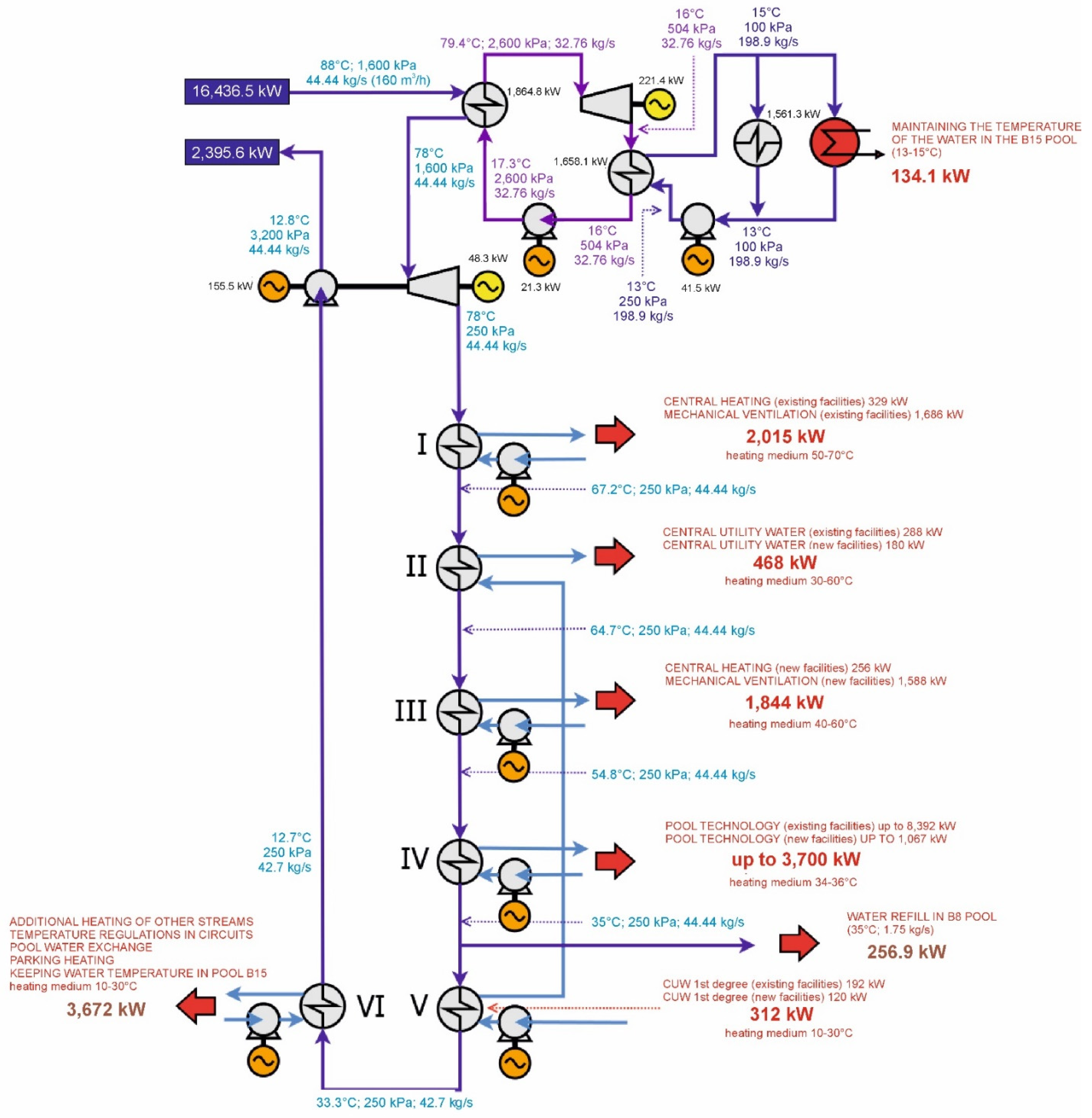
3.2. Description of the Process Line
4. Results and Discussion
4.1. ORC Geothermal Boiler Plant with Water Turbine
4.2. Cooling Plant
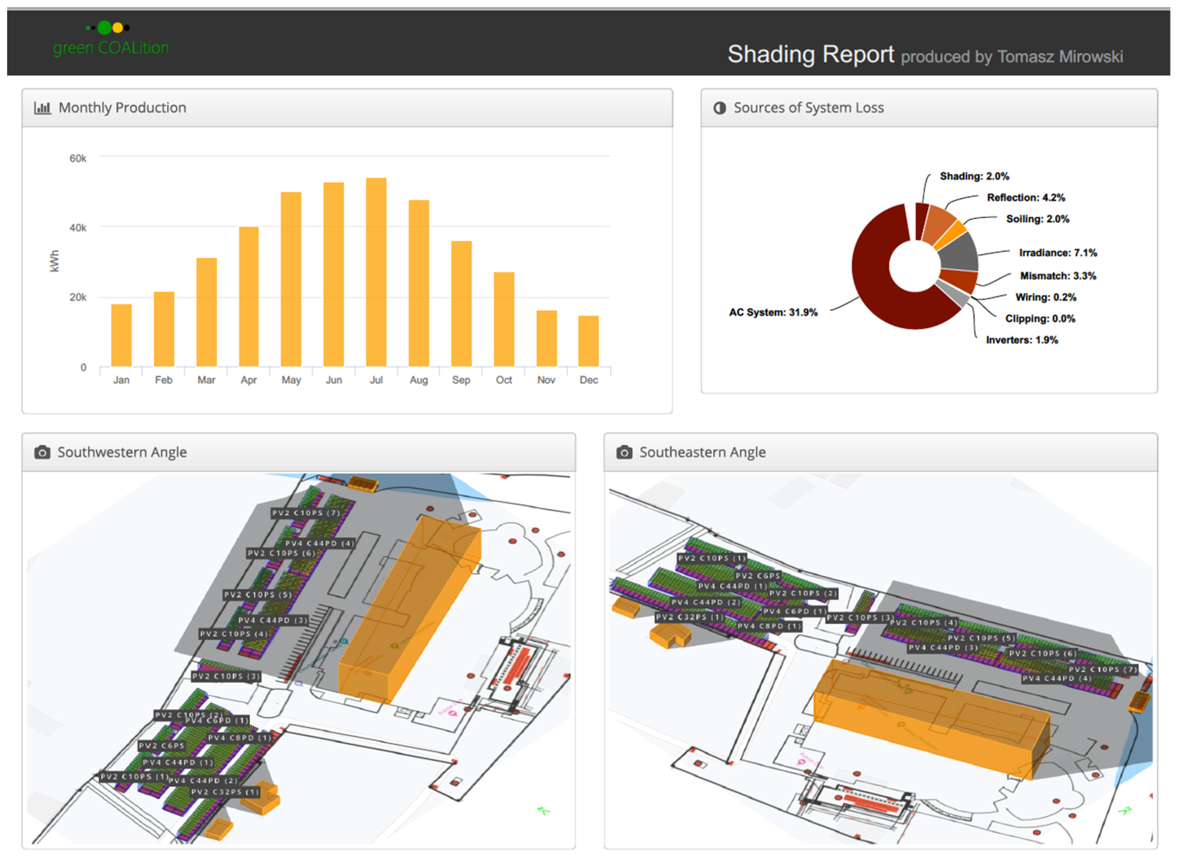
4.3. Photovoltaic Installation
4.4. Electricity Storage
- -
- The expansion is modular and scalable;
- -
- A long service life and a high number of operating cycles;
- -
- High operating efficiency;
- -
- Energy management for charging stations;
- -
- Peak power management;
- -
- Energy consumption control for photovoltaic installations;
- -
- Peak-shaving, i.e., the limitation of peak loads beyond 15 min to avoid higher charges when overconsumption occurs at the time of supply restrictions by the distribution system operator;
- -
- Remote access to data and monitoring is made possible via the internet.
4.5. Heat Storage (Buffer)
4.6. Power Balance of Loads
4.7. Environmental Indicators of the Proposed Solution
5. Conclusions
- -
- Optimizes the use of RES;
- -
- Minimizes the use of conventional sources of energy (pollutant emissions are reduced);
- -
- The geothermal plant is expanded into a multiple geothermal-photovoltaic-water plant;
- -
- The heat and electricity produced can be stored;
- -
- Sustainable development of geothermal power plants is needed to avoid climate change;
- -
- The environmental effect of the HGS system will be an increase in avoided emissions of CO2—1900 t/year, SO2—1691 kg/year, NOx—1567 kg/year, CO—683 kg/year, and dust—89 kg/year.
Author Contributions
Funding
Institutional Review Board Statement
Informed Consent Statement
Acknowledgments
Conflicts of Interest
References
- Directive (EU) 2009/28/EC of the European Parliament and of the Council of 23 April 2009 on the Promotion of the Use of Energy from Renewable Sources and Amending and Subsequently Repealing Directives 2001/77/EC and 2003/30/EC. Available online: http://eur-lex.europa.eu/legal-content/EN/TXT/HTML/?uri=CELEX:32009L0028&from=EN (accessed on 3 July 2022).
- Directive (EU) 2018/2001 Directive (EU) 2018/2001 of the European Parliament and of the Council of 11 December 2018 on the Promotion of the Use of Energy from Renewable Sources. PE/48/2018/REV/1 2018. Available online: https://eur-lex.europa.eu/legal-content/EN/TXT/?uri=CELEX%3A32018L2001 (accessed on 3 July 2022).
- Proposal for a Directive of the European Parliament and of the Council Amending Directive (EU) 2018/2001 of the European Parliament and of the Council, Regulation (EU) 2018/1999 of the European Parliament and of the Council and Directive 98/70/EC of the European Parliament and of the Council as Regards the Promotion of Energy from Renewable Sources, and Repealing Council Directive (EU) 2015/652. Available online: https://eur-lex.europa.eu/legal-content/EN/TXT/?uri=CELEX:52021PC0557 (accessed on 3 July 2022).
- EU′s Objective of Climate Neutrality by 2050-A European Green Deal. Available online: https://ec.europa.eu/info/strategy/priorities-2019-2024/european-green-deal_en (accessed on 3 July 2022).
- Olabi, A.G.; Abdelkareem, M.A. Renewable Energy and Climate Change. Renew. Sustain. Energy Rev. 2022, 158, 112111. [Google Scholar] [CrossRef]
- Surma, G.; Zabaniotou, A. Understanding Vulnerabilities of Renewable Energy Systems for Building Their Resilience to Climate Change Hazards: Key Concepts and Assessment Approaches. Renew. Energy Environ. Sustain. 2021, 6, 10. [Google Scholar] [CrossRef]
- Kaczmarczyk, M.; Tomaszewska, B.; Operacz, A. Sustainable Utilization of Low Enthalpy Geothermal Resources to Electricity Generation through a Cascade System. Energies 2020, 13, 2495. [Google Scholar] [CrossRef]
- Suman, A. Role of Renewable Energy Technologies in Climate Change Adaptation and Mitigation: A Brief Review from Nepal. Renew. Sustain. Energy Rev. 2021, 151, 111524. [Google Scholar] [CrossRef]
- Sowiżdżał, A.; Chmielowska, A.; Tomaszewska, B.; Operacz, A.; Chowaniec, J. Could geothermal water and energy use improve living conditions? Environmental effects from Poland. Arch. Environ. Prot. 2019, 45, 109–118. [Google Scholar] [CrossRef]
- Arens, M.; Åhman, M.; Vogl, V. Which Countries Are Prepared to Green Their Coal-Based Steel Industry with Electricity? - Reviewing Climate and Energy Policy as Well as the Implementation of Renewable Electricity. Renew. Sustain. Energy Rev. 2021, 143, 110938. [Google Scholar] [CrossRef]
- Karimov, K.S.; Akhmedov, K.M.; Abid, M.; Petrov, G.N. Effective management of combined renewable energy resources in Tajikistan. Sci. Total Environ. 2013, 461, 835–838. [Google Scholar] [CrossRef]
- Bagherian, M.A.; Mehranzamir, K. A comprehensive review on renewable energy integration for combined heat and power production. Energy Convers. Manag. 2020, 224, 113454. [Google Scholar] [CrossRef]
- Gudmundsson, J.; Freeston, D.; Lienau, P. The Lindal diagram. GRC Trans. 1985, 9, 15–17. [Google Scholar]
- Mirfallah Lialestani, S.; Parcerisa, D.; Himi, M.; Abbaszadeh Shahri, A. Generating 3D Geothermal Maps in Catalonia, Spain Using a Hybrid Adaptive Multitask Deep Learning Procedure. Energies 2022, 15, 4602. [Google Scholar] [CrossRef]
- Zhu, Z.; Lei, X.; Xu, N.; Shao, D.; Jiang, X.; Wu, X. Integration of 3D Geological Modeling and Geothermal Field Analysis for the Evaluation of Geothermal Reserves in the Northwest of Beijing Plain, China. Water 2020, 12, 638. [Google Scholar] [CrossRef] [Green Version]
- Aghahosseini, A.; Breyer, C. From hot rock to useful energy: A global estimate of enhanced geothermal systems potential. Appl. Energy 2020, 279, 115769. [Google Scholar] [CrossRef]
- Operacz, A.; Chowaniec, J. Perspectives of Geothermal Water Use in the Podhale Basin According to Geothermal Step Distribution. Geol. Gephysics Environ. 2018, 44, 379. [Google Scholar] [CrossRef]
- Schiel, K.; Baume, O.; Caruso, G.; Leopold, U. GIS-Based Modelling of Shallow Geothermal Energy Potential for CO2 Emission Mitigation in Urban Areas. Renew. Energy 2016, 86, 1023–1036. [Google Scholar] [CrossRef]
- Meng, F.; Liang, X.; Xiao, C.; Wang, G. Geothermal Resource Potential Assessment Utilizing GIS - Based Multi Criteria Decision Analysis Method. Geothermics 2021, 89, 101969. [Google Scholar] [CrossRef]
- Navarro, A.; Carulla, N. Evaluation of Geothermal Potential in the Vicinity of the Flooded Sierra Almagrera Mines (Almeria, SE Spain). Mine Water Environ. 2018, 37, 137–150. [Google Scholar] [CrossRef]
- Daniele, L.; Taucare, M.; Viguier, B.; Arancibia, G.; Aravena, D.; Roquer, T.; Sepúlveda, J.; Molina, E.; Delgado, A.; Muñoz, M.; et al. Exploring the Shallow Geothermal Resources in the Chilean Southern Volcanic Zone: Insight from the Liquiñe Thermal Springs. J. Geochem. Explor. 2020, 218, 106611. [Google Scholar] [CrossRef]
- Wątor, K.; Zdechlik, R. Application of Water Quality Indices to the Assessment of the Effect of Geothermal Water Discharge on River Water Quality-Case Study from the Podhale Region (Southern Poland). Ecol. Indic. 2021, 121, 107098. [Google Scholar] [CrossRef]
- Tomaszewska, B.; Szczepański, A. Possibilities for the Efficient Utilisation of Spent Geothermal Waters. Environ. Sci. Pollut. Res. 2014, 21, 11409–11417. [Google Scholar] [CrossRef]
- Markó, Á.; Mádl-Szőnyi, J.; Brehme, M. Injection Related Issues of a Doublet System in a Sandstone Aquifer-A Generalized Concept to Understand and Avoid Problem Sources in Geothermal Systems. Geothermics 2021, 97, 102234. [Google Scholar] [CrossRef]
- Liu, Y.; Hou, J.; Zhao, H.; Liu, X.; Xia, Z. Numerical Simulation of Simultaneous Exploitation of Geothermal Energy and Natural Gas Hydrates by Water Injection into a Geothermal Heat Exchange Well. Renew. Sustain. Energy Rev. 2019, 109, 467–481. [Google Scholar] [CrossRef]
- Bugajski, P.; Nowobilska-Majewska, E.; Nowobilska-Luberda, A.; Bergel, T. The Use of Geothermal Waters in Podhale in Terms of Tourism and Industrial Applications. J. Ecol. Eng. 2017, 18, 158–191. [Google Scholar] [CrossRef]
- Bujakowski, W.; Barbacki, A. Potential for Geothermal Development in Southern Poland. Geothermics 2004, 33, 383–395. [Google Scholar] [CrossRef]
- Bujakowski, W.; Tomaszewska, B.; Miecznik, M. The Podhale Geothermal Reservoir Simulation for Long-Term Sustainable Production. Renew. Energy 2016, 99, 420–430. [Google Scholar] [CrossRef]
- Operacz, A.; Bielec, B.; Tomaszewska, B.; Kaczmarczyk, M. Physicochemical Composition Variability and Hydraulic Conditions in a Geothermal Borehole—The Latest Study in Podhale Basin, Poland. Energies 2020, 13, 3882. [Google Scholar] [CrossRef]
- Józefko, I.; Bielec, B. Hydrogeological Documentation Establishing the Exploitation Resources of the “Chochołów PIG-1” Geothermal Borehole in Witów, Commune Kościelisko. Voiv. Lesser Poland. 5638/2009; CAG PIG: Warszawa, Poland, 2009. (In Polish) [Google Scholar]
- DiPippo, R. Geothermal Power Plants: Principles, Applications, Case Studies and Environmental Impact. In Library of Congress Cataloging-in-Publication Data; Elsevier Ltd.: Amsterdam, The Netherlands, 2012. [Google Scholar]
- National database on emissions of greenhouse gases and other substances—KOBiZE. Available online: https://www.kobize.pl (accessed on 11 April 2021). (In Polish).
- Tocci, L.; Pal, T.; Pesmazoglou, I.; Franchetti, B. Small Scale Organic Rankine Cycle (ORC): A Techno-Economic Review. Energies 2017, 10, 413. [Google Scholar] [CrossRef]
- Quoilin, S.; Declaye, S.; Tchanche, B.F.; Lemort, V. Thermo-Economic Optimization of Waste Heat Recovery Organic Rankine Cycles. Appl. Therm. Eng. 2011, 31, 2885–2893. [Google Scholar] [CrossRef]
- Hudson, R.B. Electricity Generation. In Geothermal Energy: Utilization and Technology; Dickson, M.H., Fanelli, M., Eds.; Earthscan with UNESCO: Paris, France, 2005. [Google Scholar]
- Pernecker, G. ORC Plant Altheim—A Progress Report Electricity generation from Enhanced Geothermal Systems. In Workshop ENGINE 5; BRGM: Strasbourg, France, 2006. [Google Scholar]
- Kaczmarczyk, M.; Tomaszewska, B.; Pająk, L. Geological and Thermodynamic Analysis of Low Enthalpy Geothermal Resources to Electricity Generation Using ORC and Kalina Cycle Technology. Energies 2020, 13, 1335. [Google Scholar] [CrossRef]
- Operacz, A. Possibility of Hydropower Development: A Simple-to-Use Index. Energies 2021, 14, 2764. [Google Scholar] [CrossRef]
- Boys, C.A.; Pflugrath, B.D.; Mueller, M.; Pander, J.; Deng, Z.D.; Geist, J. Physical and Hydraulic Forces Experienced by Fish Passing through Three Different Low-Head Hydropower Turbines. Mar. Freshwater Res. 2018, 69, 1934. [Google Scholar] [CrossRef]
- Operacz, A. The Term “Effective Hydropower Potential” Based on Sustainable Development–an Initial Case Study of the Raba River in Poland. Renew. Sustain. Energy Rev. 2017, 75, 1453–1463. [Google Scholar] [CrossRef]
- Green, M.A. The Passivated Emitter and Rear Cell (PERC): From Conception to Mass Production. Sol. Energy Mater. Sol. Cells 2015, 143, 190–197. [Google Scholar] [CrossRef]
- Preu, R.; Lohmüller, E.; Lohmüller, S.; Saint-Cast, P.; Greulich, J.M. Passivated Emitter and Rear Cell—Devices, Technology, and Modeling. Appl. Phys. Rev. 2020, 7, 041315. [Google Scholar] [CrossRef]
- Modanese, C.; Laine, H.; Pasanen, T.; Savin, H.; Pearce, J. Economic Advantages of Dry-Etched Black Silicon in Passivated Emitter Rear Cell (PERC) Photovoltaic Manufacturing. Energies 2018, 11, 2337. [Google Scholar] [CrossRef]
- A New Performance Record for PERC Modules! Available online: https://globenergia.pl/nowy-rekord-wydajnosci-modulow-perc/ (accessed on 3 July 2022). (In Polish).
- Smart Power Station. Available online: https://sps.zpue.pl/ (accessed on 3 July 2022).
- Dahash, A.; Ochs, F.; Janetti, M.B.; Streicher, W. Advances in seasonal thermal energy storage for solar district heating applications: A critical review on large-scale hot-water tank and pit thermal energy storage systems. Appl. Energy 2019, 239, 296–315. [Google Scholar] [CrossRef]
- Dahash, A.; Ochs, F.; Tosatto, A. Techno-economic and exergy analysis of tank and pit thermal energy storage for renewables district heating systems. Renew. Energy 2021, 180, 1358–1379. [Google Scholar] [CrossRef]
- Announcement of the Minister of Climate and Environment of 2 March 2021 on the State’s Energy Policy until 2040. Polish Monitor 2021, Item 264. Available online: https://www.gov.pl/web/klimat/polityka-energetyczna-polski (accessed on 3 July 2022). (In Polish)
- Theiss Thermal Power Plant. Available online: https://www.logstrup.com/case-studies/theiss-thermal-power-plant-9/ (accessed on 1 July 2022).
- World Largest Thermal Heat Storage Pit in Vojens. Available online: https://stateofgreen.com/en/solutions/world-largest-thermal-pit-storage-in-vojens/ (accessed on 1 July 2022).


| Exploiting Capacity Q (m3/h) | Temperature at the Outflow T (°C) | Static Water Table (m a.s.l./m a.g.l) | Dynamic Water Table (m a.s.l./m a.g.l) | Chemical Type |
|---|---|---|---|---|
| 160 | t = 89.8 °C | 945.0/155.46 | 799.5/10.0 | 0.11%SO4-Ca-Mg-Na |
| Thermal Power [kW] | Current | New Facilities | Total |
|---|---|---|---|
| (1) Central heating | 329 | 56 | 585 |
| (2) Pool heating | 8392 | 1067 | 9459 |
| (3) Process needs | 1686 | 1588 | 3274 |
| (4) DHW | 480 | 300 | 780 |
| (5) De-icing | 555 | - | 555 |
| (6) B8 pool supplementation | 256.9 | - | 256.9 |
| TOTAL | 11,698.9 | 3211 | 14,909.9 |
| Working Medium in an ORC Plant | Upper Heat Source | Thermal Water Parameters Downstream of the ORC Plant | Lower Heat Source |
|---|---|---|---|
| Toluene, R-114, R-135a or R-152a | Thermal water from a borehole with a temperature of 88 °C and an absolute pressure of 16 bar, with a water flow of 20–160 t/h | temperature 85–70 °C | Atmospheric air (fan coolers) or river water (open system, heating the water by no more than 3 °C) |
| Cooling Power (kW) | Current | Newly Designed Facilities | Total |
|---|---|---|---|
| Demand | 324 | 3803 | 4127 |
| Actual power installed | 550 | 3803 | 4353 |
| Month | Global Horizontal Irradiance (kWh/m2) | POA Irradiance (kWh/m2) | Shaded (kWh/m2) | Nameplate (kWh) | Grid (kWh) |
|---|---|---|---|---|---|
| January | 37.0 | 45.4 | 42.2 | 27,082.2 | 18,032.4 |
| February | 45.1 | 51.5 | 50.0 | 32,320.0 | 21,568.0 |
| March | 72.5 | 77.4 | 76.1 | 49,510.8 | 31,330.0 |
| April | 97.5 | 101.4 | 99.9 | 65,138.9 | 40,092.6 |
| May | 130.3 | 132.5 | 130.7 | 84,963.5 | 50,198.5 |
| June | 142.0 | 142.9 | 140.9 | 92,006.3 | 52,864.1 |
| July | 146.1 | 148.5 | 146.4 | 95,432.1 | 54,114.6 |
| August | 127.2 | 131.3 | 129.6 | 84,694.0 | 47,904.7 |
| September | 88.4 | 94.4 | 93.0 | 60,476.6 | 36,207.9 |
| October | 59.9 | 65.1 | 64.0 | 41,553.7 | 27,173.6 |
| November | 31.8 | 35.1 | 34.2 | 22,064.8 | 16,073.8 |
| December | 29.0 | 34.3 | 31.7 | 20,403.9 | 14,717.9 |
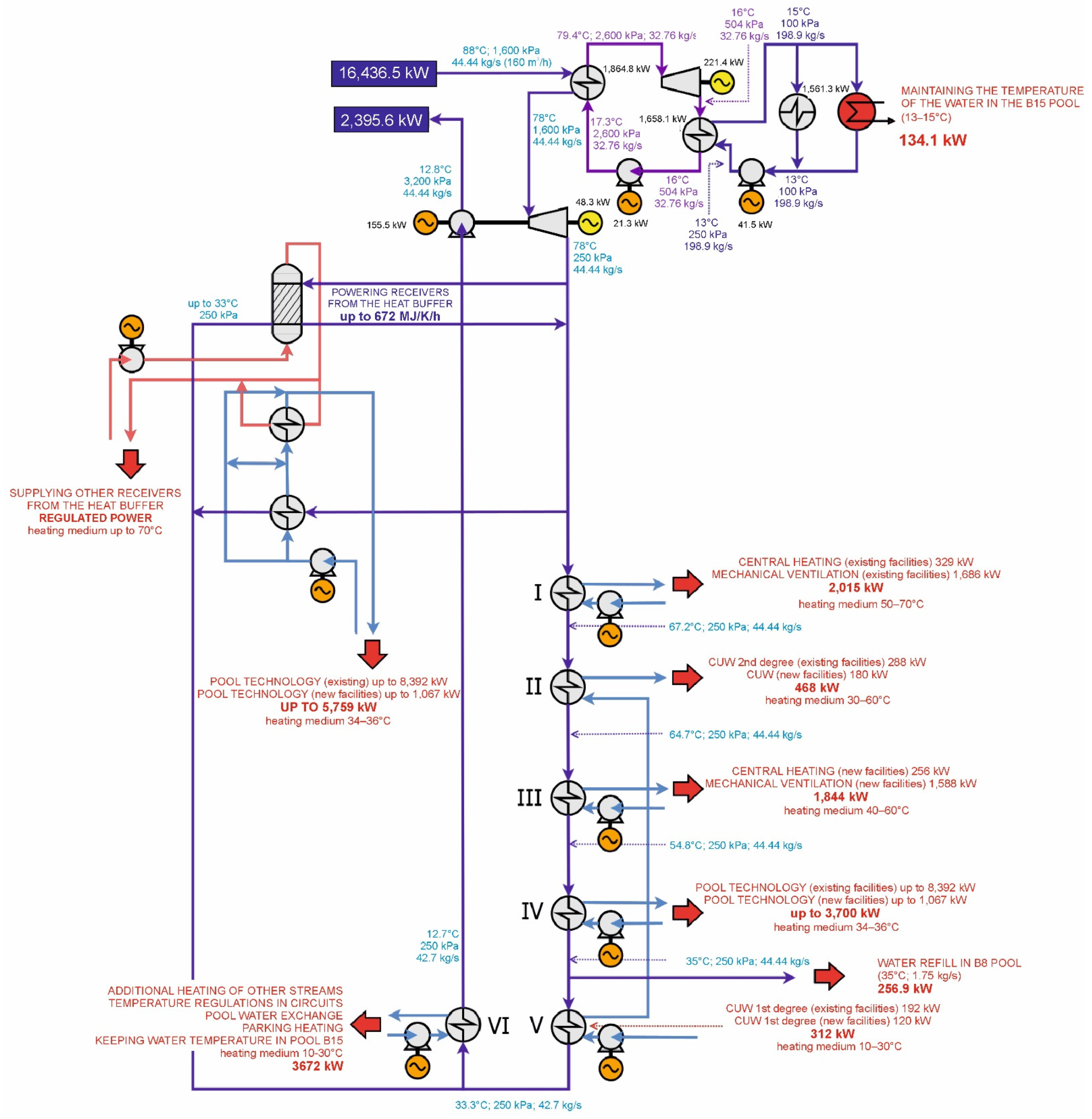
| Name of Heat Receiver acc. to Figure 7 | Heat Receiver Capacity, kW | Description of the Receiver |
|---|---|---|
| ORC | 1864.8 | Heat from the ORC to maintain the water temperature in pool B15 (13–15 °C) |
| Surplus/buffer | 5759 | Use of a buffer (thermal energy store) to stabilize operation during peak times of the district heating section |
| I stage | 2015 | Central heating 329 kW (existing facilities) and ventilation 1686 kW (existing facilities) |
| II stage | 468 | DHW—II stage 288 kW (existing facilities), DHW—II stage 180 kW (new facilities) |
| III stage | 1844 | Central heating 256 kW (new facilities) and ventilation 1588 kW (new facilities) |
| IV stage | 3700 | Pool technology up to 8392 kW (existing facilities), pool technology up to 1067 kW (new facilities). |
| Supplementing water in the pool | 276.5 | Water discharge at 35 °C and flow rate of 1.44 kg/s for supplementing swimming pools |
| V stage | 312 | DHW—I stage 192 kW (existing facilities) DHW—I stage 120 kW (new facilities) |
| VI stage | 3688 | Reheating of other streams, pool water control, pool water exchange, car park heating, pool temperature maintenance of B15 |
| TOTAL | 18,062.5 |
| Heat Load Capacity (kW) | Total Demand (kW) | Heat Load Used at Nominal Conditions (kW) | Heat Load Withdrawn from Source, Including ORC (kW) | Demand from Receivers with Temperature > 30 °C (kW) |
|---|---|---|---|---|
| 1864.8 | 18,062.5 | 12,303.5 | 14,168.3 | 14,374.5 |
| Power [kW] | Hours/Day | Days/Month | Months/Year | Unevenness Factor | Total [mWh] | |
|---|---|---|---|---|---|---|
| Cloakroom (level -1), central heating | 26 | 6 | 30 | 6 | 1.2 | 33.7 |
| Building (other levels), central heating | 230 | 6 | 30 | 6 | 1.2 | 298.08 |
| Cloakroom (level -1), ventilation | 36 | 24 | 30 | 6 | 1.2 | 186.62 |
| Building (other levels), ventilation | 1552 | 24 | 30 | 6 | 1.2 | 8046.71 |
| DHW | 300 | 24 | 30 | 12 | 1.0 | 2592.00 |
| Swimming pool water technology | 1067 | 24 | 30 | 6 | 1.5 | 6914.16 |
| Total | 3211 | 18,071.27 |
Publisher’s Note: MDPI stays neutral with regard to jurisdictional claims in published maps and institutional affiliations. |
© 2022 by the authors. Licensee MDPI, Basel, Switzerland. This article is an open access article distributed under the terms and conditions of the Creative Commons Attribution (CC BY) license (https://creativecommons.org/licenses/by/4.0/).
Share and Cite
Operacz, A.; Zachora-Buławska, A.; Strzelecka, I.; Buda, M.; Bielec, B.; Migdał, K.; Operacz, T. The Standard Geothermal Plant as an Innovative Combined Renewable Energy Resources System: The Case from South Poland. Energies 2022, 15, 6398. https://doi.org/10.3390/en15176398
Operacz A, Zachora-Buławska A, Strzelecka I, Buda M, Bielec B, Migdał K, Operacz T. The Standard Geothermal Plant as an Innovative Combined Renewable Energy Resources System: The Case from South Poland. Energies. 2022; 15(17):6398. https://doi.org/10.3390/en15176398
Chicago/Turabian StyleOperacz, Agnieszka, Agnieszka Zachora-Buławska, Izabela Strzelecka, Mariusz Buda, Bogusław Bielec, Karolina Migdał, and Tomasz Operacz. 2022. "The Standard Geothermal Plant as an Innovative Combined Renewable Energy Resources System: The Case from South Poland" Energies 15, no. 17: 6398. https://doi.org/10.3390/en15176398
APA StyleOperacz, A., Zachora-Buławska, A., Strzelecka, I., Buda, M., Bielec, B., Migdał, K., & Operacz, T. (2022). The Standard Geothermal Plant as an Innovative Combined Renewable Energy Resources System: The Case from South Poland. Energies, 15(17), 6398. https://doi.org/10.3390/en15176398