Article

Improved Frequency Control Strategy for Offshore Wind Farm Integration via VSC-HVDC

Key Laboratory of Smart Grid, Ministry of Education, Tianjin University, Tianjin 300072, China
*
Author to whom correspondence should be addressed.
Energies 2022, 15(17), 6363; https://doi.org/10.3390/en15176363
Submission received: 17 June 2022 / Revised: 13 August 2022 / Accepted: 16 August 2022 / Published: 31 August 2022
(This article belongs to the Special Issue Advances in DC Technology for Modern Power Systems)

Abstract

:
Voltage source converter based high voltage DC system (VSC-HVDC) has become a very promising solution to integrate offshore wind farm. However, the equivalent inertia of the modern power system with large renewable energy integration becomes small, which will arouse some frequency stability problems. To tackle this problem, this paper proposes an improved frequency regulation strategy for VSC-HVDC integrated offshore wind farm. Firstly, in the frequency decrease stage, the rotor kinetic energy of wind turbines (WTs) is used to suppress the decrease of the frequency, and the control parameters are determined to make full use of the mechanical power and rotor kinetic energy of WTs, the frequency nadir is improved. Secondly, in the rotor speed recovery stage, the DC capacitors of VSC-HVDC are used to release power to compensate the deficiency value of wind farm output power and avoid the secondary frequency drop (SFD) problem. Lastly, the simulation is conducted in PSCAD/EMTDC to validate the effectiveness of the proposed coordinated frequency control strategy.

1. Introduction

Connecting offshore wind farm to AC system through voltage source converter based high voltage DC system (VSC-HVDC) can optimize the output of wind farm, improve the power generation efficiency, and improve the operation stability of the whole system [1,2,3,4]. With the increase of installed capacity of wind farms, the overall equivalent inertia of the AC system becomes smaller, which will arouse the frequency stability problem. Meanwhile, VSC-HVDC decouples the wind farm from the adjacent AC system [5,6,7]. Therefore, the safe and stable operation of the system will be greatly affected.
Wind turbines (WTs) usually operates under maximum power point tracking (MPPT) mode, and the rotor speed is decoupled from the system frequency. To make WTs participate in system frequency regulation, experts and scholars have conducted a lot of research and proposed different frequency regulation strategies, includes rotor kinetic energy control, over-speed control and auxiliary control of energy storage devices [8,9,10].
In the rotor kinetic energy control strategy, the rotor initially operates at the MPPT. When the system frequency fluctuates, the rotor releases or absorbs kinetic energy by the comprehensive inertia control to participate in the frequency control. However, the frequency regulation parameters of the comprehensive inertia control are difficult to be set properly [11,12]. Too small parameters will lead to insufficient utilization of rotor kinetic energy, and too large parameters will lead to rotor speeds exceeding the safe operation range. In addition, there is a problem of secondary frequency droop (SFD) during the recovery stage of rotor speed [13,14]. In [15], the specific influences of droop and inertia coefficients on system frequency are analyzed. To avoid the sudden reduction of WTs output power and reduce the influence of SFD during the recovery stage of rotor speed, Ref. [16] proposes a method to gradually reduce the additional output power of frequency regulation to 0 during the recovery stage of rotor speed. In [17], authors use WTs with a high rotor speed to carry out the primary frequency control, and the WTs with the low speed to reduce the SFD of the system. However, the proposed strategy may still lead to another frequency droop.
To avoid SFD problem, a coordinated control method of overspeed control and pitch angle control to reserve a certain power for wind farms to provide long-term frequency regulation [18]. However, pitch angle control may take quite a long time, and frequent actions will cause fatigue damage of WTs. Meanwhile, overspeed control reduces the utilization rate of wind power, which is also not an ideal choice. In recent years, with the rapid development of energy storage technology, energy storage devices have been widely used in photovoltaic power plant and wind farm to participate in frequency control. Ref. [19] uses flywheel energy storage device to stabilize the power fluctuation of wind farm and improve the frequency stability. Ref. [20] uses a supercapacitor for double fed induction generators (DFIG) to realize the inertia control and droop control. However, the effect of frequency regulation provided only by the capacitor is not satisfactory, and the supercapacitor is expensive. For VSC-HVDC, the converter station contains a certain capacitance and has a certain frequency regulation potential. In [21], authors propose to control the DC side voltage of VSC-HVDC to release the capacitor energy to participate in the system frequency regulation and improve the equivalent inertia of the system. However, the energy stored in the DC capacitor of the converter is limited, so it cannot participate in the system frequency regulation for a long time. In sum, the kinetic energy of the WTs and the stored energy of the capacitor of the VSC should be used in a proper way to improve the frequency performance of the adjacent AC system.
The main contribution of this paper can be summarized as below:
(1)
An improved frequency regulation strategy for VSC-HVDC integrated offshore wind farm is proposed, which consists of the frequency decrease stage and the rotor speed recovery stage.
(2)
In the frequency decrease stage, the frequency nadir is improved by making full use of the mechanical power and rotor kinetic energy of WTs.
(3)
In the rotor speed recovery stage, the SFD problem can be avoided by releasing the power of the DC capacitors of VSC-HVDC.
The rest of this paper is organized as follows. In Section 2, the traditional comprehensive inertial control of DFIG is introduced. The improved frequency regulation control strategy is proposed in Section 3. In Section 4, simulations of a DFIG wind farm via VSC-HVDC system under different disturbances have been conducted in PSCAD/EMTDC to validate the effectiveness of the proposed frequency control strategy. Finally, conclusions and future work are provided in Section 5.

2. The Traditional Comprehensive Inertial Control of DFIG

2.1. Wind Turbine Model

This paper takes DFIG as an example to study the frequency regulation method of wind farm.
The aerodynamic model of WT is [22,23]:
P m = 0.5 C p ( λ , β ) ρ A v 3
C p ( λ , β ) = c 1 ( c 2 / λ i c 3 β c 4 ) e c 5 / λ + c 6 λ
1 / λ i = 1 / ( λ + 0.08 β ) 0.035 / ( 1 + β 3 )
λ = ω r R / v
where P m is mechanical power of WT, C p ( λ , β ) is wind energy utilization coefficient, λ is blade tip speed ratio, β is pitch angle, ρ is air density, A is wind swept area of the wind turbine blade, v is wind speed, ω r is rotor speed, R is blade swept radius, and c 1 = 0.5176 , c 2 = 116 , c 3 = 0.4 , c 4 = 5 , c 5 = 21 , c 6 = 0.0068 . WTs can change the wind energy utilization coefficient by controlling the rotor speed ω r and pitch angle β . Usually, the rotor speed is used to control the output power of WTs accurately because the wind speed fluctuates frequently and is difficult to be captured accurately.
According to (1)–(4), the optimal power tracking curve of DFIG is:
{ P o p t = k o p t ω r 3 k o p t = 0.5 ρ C p , o p t π R 5 / λ o p t 3
where P o p t is the maximum output power, C p , o p t is the maximum wind energy utilization coefficient and λ o p t is the optimal tip speed ratio.

2.2. Traditional Comprehensive Inertial Control

According to [24], the safe operation range of DFIG rotor speed is 0.8–1.2 pu, and the rotor kinetic energy can be released or absorbed by controlling the rotor speed. The control block diagram is shown in Figure 1. Under normal operation conditions, the rotor speed is maintained at the MPPT. When the system frequency changes, the system frequency deviation Δ f and frequency change rate d f d t obtain the incremental power Δ P 1 and Δ P 2 by the droop control and the inertia control, respectively.
In Figure 1, K W 1 and K W 2 are the droop coefficient and inertia coefficient, respectively. The relationship between DFIG output power P and rotor speed ω r under comprehensive inertia control is shown in Figure 2. After a certain time (suppose the rotor speed at this time is ω T ), cutting off the comprehensive inertia control link for some safety reasons, the output power of DFIG will drop instantaneously, which will cause the frequency to drop again.
It is difficult to determine the droop coefficient and inertia coefficient of the comprehensive inertia control. If the parameters are too small, the rotor kinetic energy will not be fully utilized, and the system frequency will not be effectively improved. If the parameters are too large, the rotor speed will change too fast, resulting in serious SFD during the rotor speed recover stage.

3. Improved Frequency Control Strategy

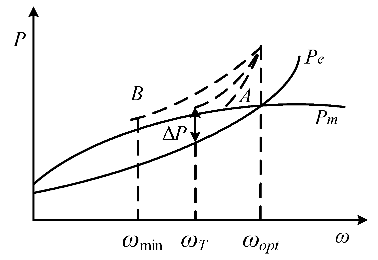
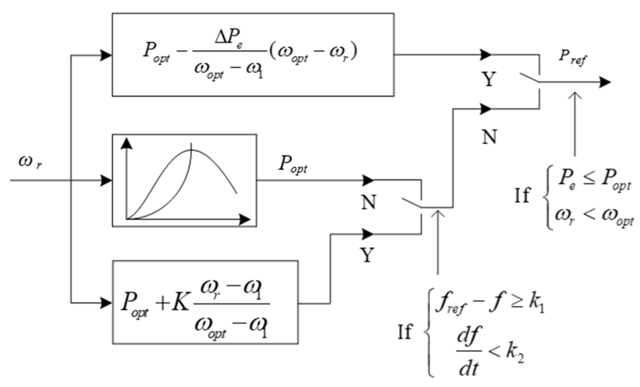
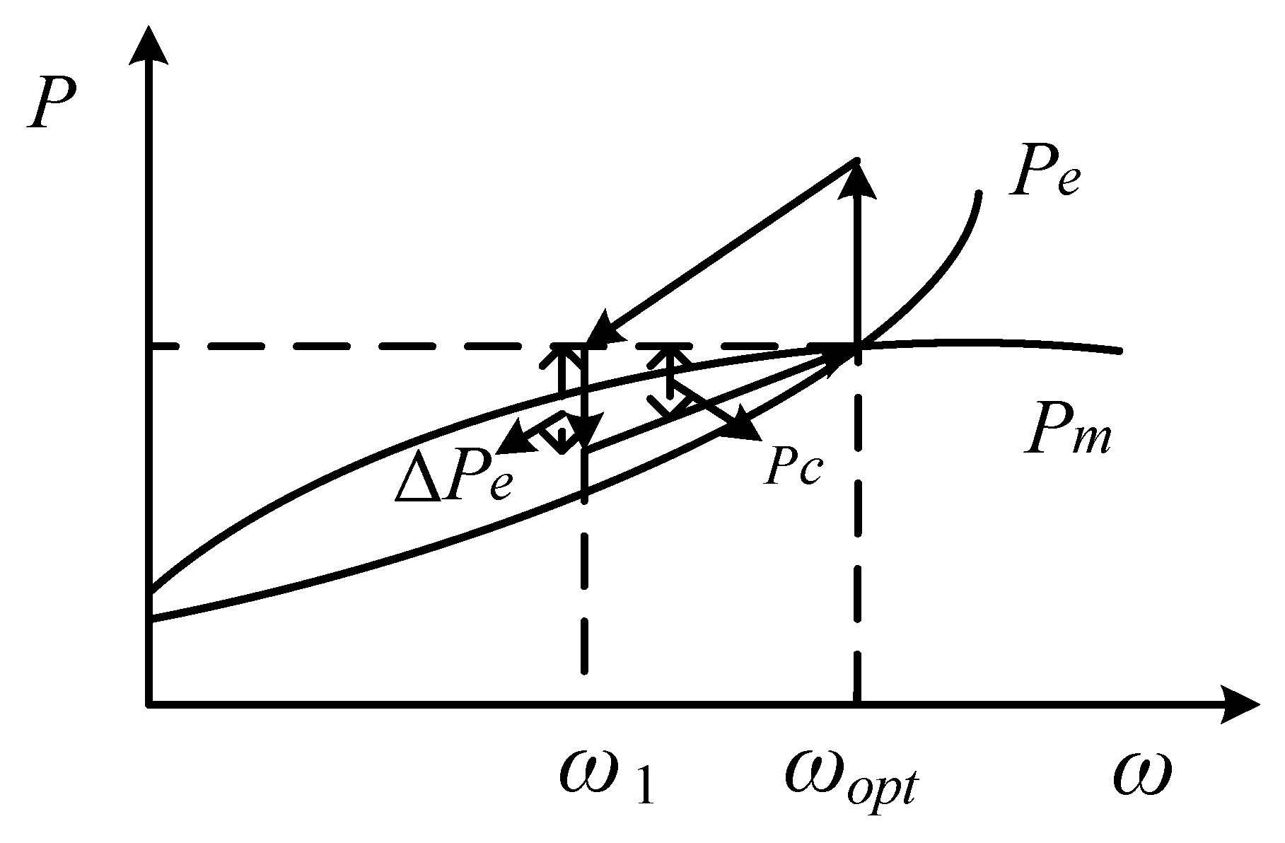
3.1. Improved Rotor Kinetic Energy Control Strategy

As shown in Figure 3, the improved frequency control strategy is proposed based on the relationship of rotor speed and the output power.
The trigger condition of the novel frequency control strategy is f r e f f k 1 and d f d t < k 2 . According to [25], k 1 is set to be 0.03 and k 2 is set to be 0. When the frequency regulation trigger conditions are met, the reference value of DFIG output power is shown as below:
P r e f = P o p t + K ω r ω 1 ω o p t ω 1
where K is the adjustment parameter, ω 1 is the lowest set speed point.
According to (6), the WTs has the maximum output power at the primary stage of system frequency drop, which can effectively reduce the system frequency change rate. During the deceleration process of WTs, the output power and rotor speed of WTs gradually decreases, the rotor kinetic energy is released, and the nadir of the system frequency is improved. The reference value of output power will decelerate the rotor speed from the optimal power operation point to the set speed point ω 1 .

3.2. The Adjustment Parameter K

In the process of frequency regulation, the output power of WTs shall always be greater than the output power P o p t without participating in frequency regulation. Therefore, the lowest point of output power is set as P o p t . ω 1 is the lowest set speed point of rotor. The time the rotor kinetic energy participates in frequency regulation is set as T r e s p o n s e , which means the rotor speed drops from ω o p t to ω 1 after T r e s p o n s e . In this paper, T r e s p o n s e is selected to be 4.8 s.
Suppose that the system load increases suddenly at t 0 , then the frequency decreases, and the kinetic energy released during frequency decrease stage, is:
Δ E k = 1 2 J ( ω o p t 2 ω 1 2 )
The additional output electromagnetic energy of WTs is:
Δ E = t 0 t 0 + T r e s p o n s e P o p t + K ω r ω 1 ω o p t ω 1 P m   d t
During the period of rotor frequency regulation, the additional electromagnetic power comes from the kinetic energy released by the rotor, so
Δ E k = Δ E
Supposing that the rotor speed changes linearly during deceleration, we have
ω r = ω o p t ω o p t ω 1 T r e s p o n s e ( t t 0 )
Once the lowest rotor speed ω 1 is determined, the value of the adjustment parameter K can be calculated by (7)–(10).
The change of DFIG mechanical power and output power during the frequency regulation process is shown in Figure 4.
When the rotor speed reaches to ω 1 , the output power of DFIG decreases to P o p t . If the drop of output power is Δ P e , the mechanical input power is greater than the output power, and the rotor speed begins to recover. During the recovery stage of rotor speed, the reference value of DFIG output power is given as (11):
P r e f = P o p t Δ P e ω o p t ω 1 ( ω o p t ω r )

3.3. Auxiliary Frequency Regulation of VSC-HVDC

This section uses the capacitor of VSC-HVDC to release short-time high power to make up for the deficiency value of DFIG output power during the recovery stage of rotor speed. For VSC-HVDC connected to offshore wind farms, the onshore VSC adopts constant DC voltage control, and the offshore VSC adopts V/f control to provide constant AC voltage and frequency for the wind farm.
When the rotor kinetic energy frequency regulation makes the rotor speed drop to the set value ω 1 , the capacitor of VSC-HVDC releases power to compensate the deficiency value of wind farm output power and maintain the output power to the system side unchanged. The active power to be compensated by the capacitor is shown in Figure 4. The power required to be provided by VSC during rotor speed recovery stage is:
P C = P o p t P e = Δ P e ω o p t ω 1 ( ω o p t ω r )
The relationship of DC capacitor power and voltage is:
P C = P i n P o u t = C U d c d U d c d t
According to (12) and (13), the reference value of DC voltage is:
U d c r e f = U d c 0 2 2 C t 0 + T r e s p o n s e t Δ P E ω o p t ω 1 ( ω o p t ω r ) d t
Based on the above analysis, it can be concluded that the improved frequency regulation strategy control process of the offshore wind farm via VSC-HVDC is as follows:
(1)
The increase of system load leads to the drop of system frequency and triggers the frequency regulation of DFIG.
(2)
The rotor speed decreases gradually. When the rotor speed reaches the set speed ω 1 , the capacitor of VSC-HVDC is triggered to release power.
(3)
The rotor speed rises, and DFIG outputs electromagnetic power according to the command. When rotor speed reaches the optimal power operation point again, DFIG and VSC-HVDC exit the frequency regulation at the same time.
(4)
When the system frequency recovers to be stable, gradually increase the DC voltage of VSC-HVDC to the rated value to prepare for the next auxiliary frequency regulation.

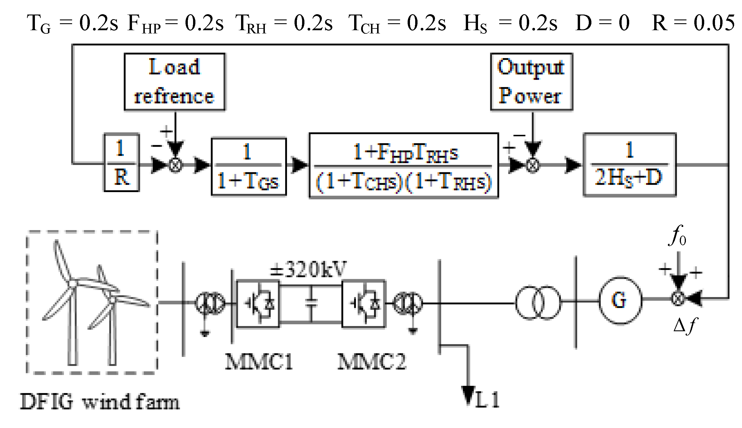
4. Simulation Studies

Simulations of a DFIG wind farm via VSC-HVDC system under different disturbances have been conducted in PSCAD/EMTDC to validate the effectiveness of the proposed frequency control strategy. The topology of the whole system is shown in Figure 5, and the parameters are shown in Table 1. The rated capacity of DFIG wind farm consisted of 60 DFIGs. The rated wind speed of DFIG is 10 m/s and the simulated wind speed is 9 m/s. In the normal operation state, wind farm operates in the maximum power tracking state, rotor speed is 0.93 pu and the output power of a single DFIG is 0.712 pu.

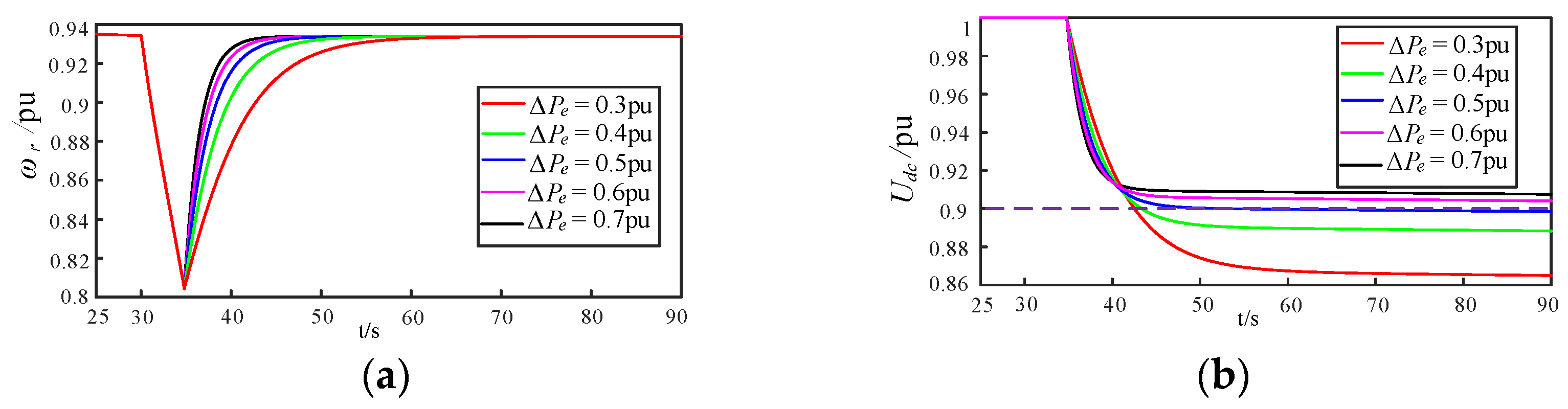
4.1. Selection of the Adjustment Parameter K

According to the above analysis, the smaller ω 1 is, the greater the released kinetic energy is, and the better the frequency regulation effect of wind farm can be. Since the capacitor of VSC-HVDC provides the deficiency value of wind farm output power during rotor speed recovery stage, ω 1 is set to 0.8 pu. Different Δ P e are selected during the recovery stage of rotor speed. The changes of rotor speed and DC voltage of VSC-HVDC are shown in Figure 6.
From Figure 6, the larger Δ P e is, the faster the rotor speed recovery and the smaller the DC voltage drop can be. When Δ P e is larger, although DC capacitor needs to provide more supplementary power in the early stage, the time required for rotor speed recovery is also shorter, resulting in less energy required for the DC capacitor to restore the rotor speed to the rated value. As shown in Figure 7, the power provided by the DC capacitor increases with the increasement of Δ P e . The DC voltage deviation limit is about ±10%, so the power sag Δ P e should be more than 0.5 pu.

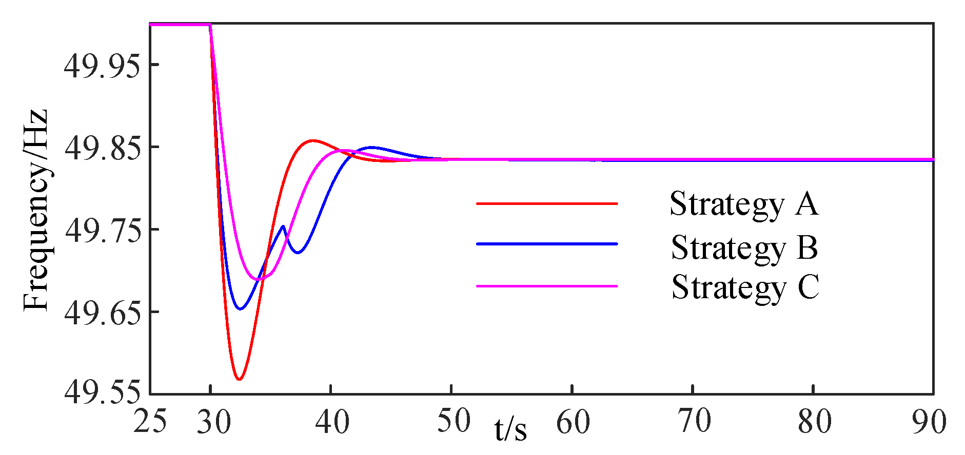
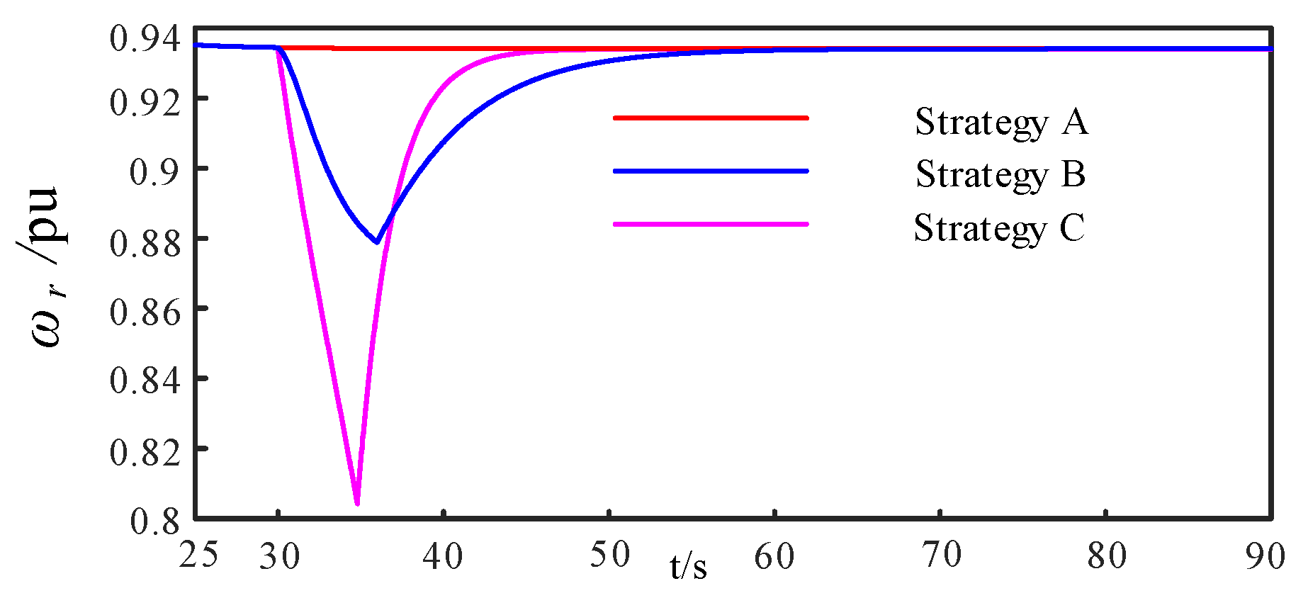
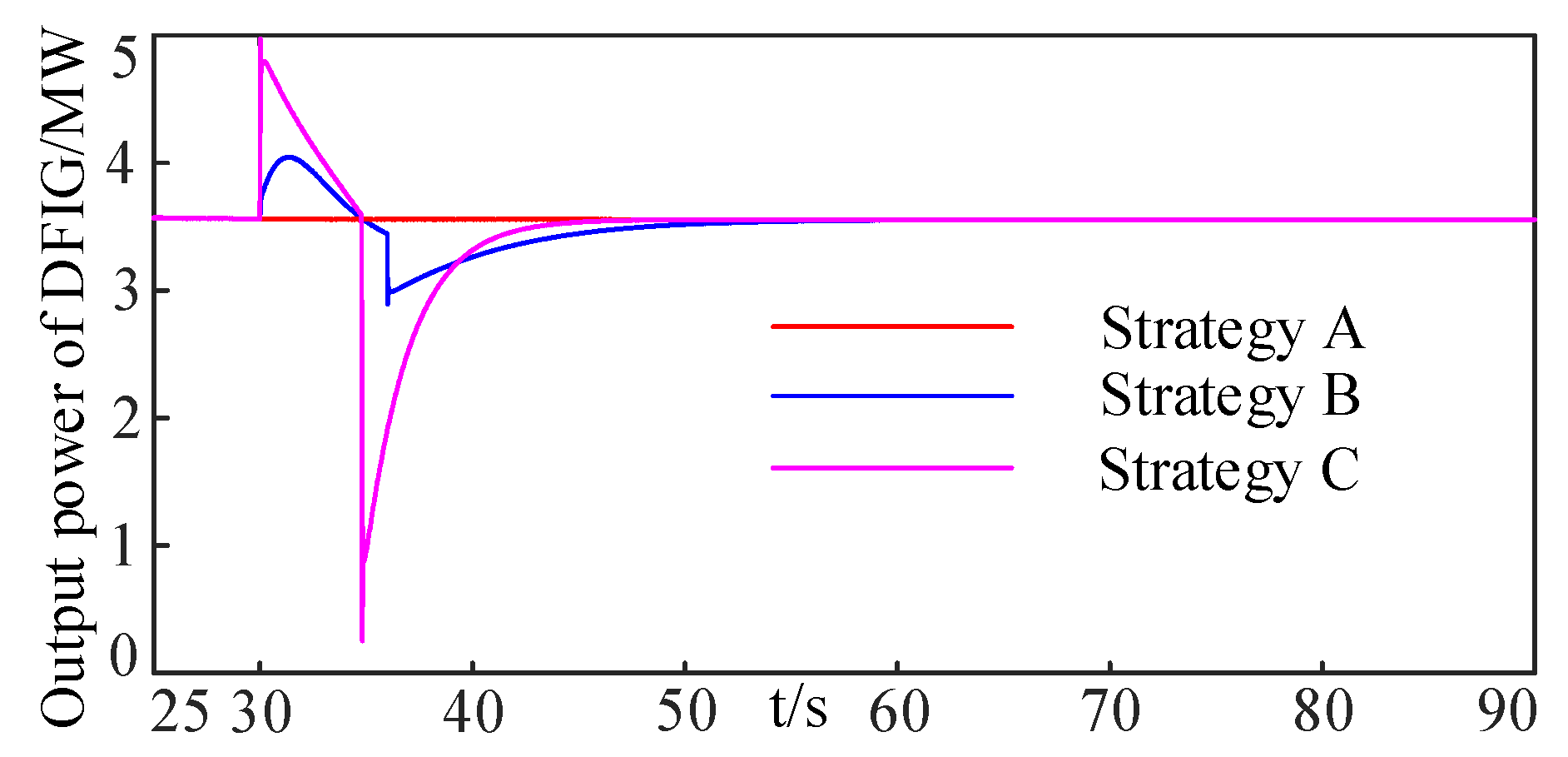
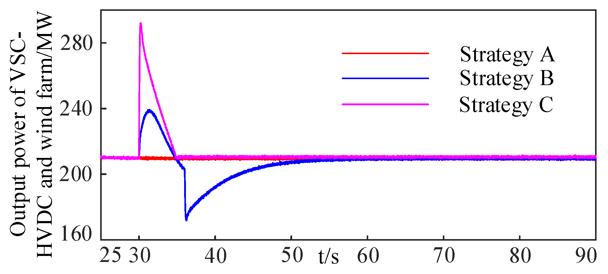
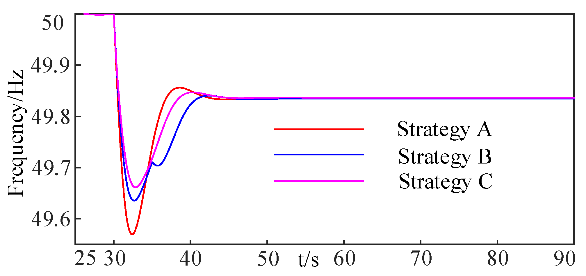
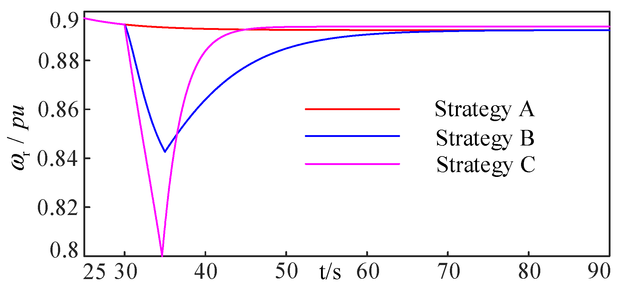
4.2. Simulation Results

In the normal operation, load L1 is 1058 MW, ω 1 is set to 0.8 pu, and the frequency regulation parameter K is 0.27. At t = 30, load L1 suddenly increases 132.25 MW. Three strategies are adopted to validate the proposed method:
Strategy A: without additional control.
Strategy B: with traditional comprehensive inertial control, where Kw1 is 20 and Kw2 is 25.
Strategy C: with proposed improved frequency control.
When the wind farm and VSC-HVDC don’t participate in the system frequency regulation, the frequency nadir is 49.57 Hz. The frequency nadir under strategy B and C is 49.66 Hz and 49.70 Hz respectively. From Figure 8, compared with strategy A and B, the frequency with the improved control strategy changes more slowly, the nadir of the system frequency is further improved, and there is no SFD problem. The proposed frequency control strategy solves the problem that frequency regulation parameters are difficult to be determined properly and make the rotor speed reduce to the lowest speed point properly. Therefore, the frequency nadir is improved in the frequency decrease stage. The capacitor of VSC-HVDC make up for the output power deficiency value of DFIG during rotor speed recovery stage. So, there is no problem of secondary frequency droop. The limit of the improved frequency control strategy is that the DC voltage of VSC needs to recover after the rotor speed recover to the MPPT point. In this way, the overall time required for primary frequency regulation of the system will be a little longer.
Figure 9 shows the rotor speed response under different control strategies. When DFIG does not participate in frequency regulation, the rotor speed is decoupled from the system frequency, the rotor speed is unchanged, the rotor speed is always 0.93 pu. Compared with the traditional comprehensive inertia control strategy, rotor speed drop of improved strategy is larger, but the time required for the recovery of the rotor speed is shorter. It can be seen from the figure that the rotor speed recovers stable after about 7 s, and the DC capacitor only needs to provide power support for about 7 s, which conforms to the characteristic of short-time high-power support of the DC capacitor.
Figure 10 shows the output power of a single DFIG with different control strategies. Compared with the traditional comprehensive inertia control, the improved control strategy has a larger output power, which improves the frequency nadir.
Figure 11 shows the active power transmitted from wind farm and VSC-HVDC to the AC side. Under the proposed strategy, the supplementary power to the AC system is always positive, so there will be no SFD problem.
When wind speed is 8 m/s, at t = 30, load L1 suddenly increases 132.25 MW. Three strategies are adopted to validate the proposed method. System frequency and rotor speed are shown in Figure 12 and Figure 13.
When the wind farm and VSC-HVDC don’t participate in the system frequency regulation, the frequency nadir is 49.57 Hz. The frequency nadir under strategy B and C are 49.63 Hz and 49.66 Hz, respectively. Compared with strategy A and B, the nadir of the system frequency with the improved control strategy is improved.
When the wind speed is 8 m/s, the rated rotor speed is 0.89 pu, compared with the traditional comprehensive inertia control strategy, rotor speed drop of the improved strategy is larger, but the time required for the recovery of rotor speed is shorter. Compared with the wind speed of 9 m/s, the available rotor kinetic energy of the WTS with the wind speed of 8 m/s is less, and the frequency regulation effect is weaker than that of 9 m/s.

5. Conclusions

In this paper, an improved frequency control strategy based on rotor kinetic energy and stored energy of VSC is proposed for offshore wind farm via VSC-HVDC system, it consists of the frequency decrease stage and the rotor speed recovery stage.
In the frequency decrease stage, the rotor kinetic energy of wind turbines (WTs) is used to suppress the decrease rate of the frequency, and the control parameters are determined to make full use of the mechanical power and rotor kinetic energy of WTs. Therefore, the frequency nadir in the frequency decrease stage is improved.
In the rotor speed recovery stage, the DC capacitors of VSC-HVDC are used to release the limited power to compensate the deficient output power of wind farm to avoid the SFD problem.
Compared with the traditional comprehensive inertia control strategy, the improved frequency control strategy effectively improves the frequency regulation capability of the offshore wind farm via VSC-HVDC system.
The coordination control of WTs and VSC should be studied further to fully explore the frequency regulation potential of offshore wind farm via VSC-HVDC system.

Author Contributions

Conceptualization, R.Z. and Y.W.; methodology, R.Z.; validation, R.Z.; supervision, Y.W.; project administration, Y.W.; funding acquisition, Y.W. All authors have read and agreed to the published version of the manuscript.

Funding

This research was funded by Science and Technology Project of State Grid Jibei Electric Power Co., Ltd. grant number 52018K20007D.

Institutional Review Board Statement

Not applicable.

Informed Consent Statement

Not applicable.

Data Availability Statement

Not applicable.

Conflicts of Interest

The authors declare no conflict of interest.

References

  1. Kunjumuhammed, L.; Pal, B.; Gupta, R.; Dykes, K. Stability Analysis of a PMSG-Based Large Offshore Wind Farm Connected to a VSC-HVDC. In Proceedings of the 2018 IEEE Power & Energy Society General Meeting (PESGM), Portland, OR, USA, 5–10 August 2018. [Google Scholar]
  2. Guo, Y.; Gao, H.; Xing, H.; Wu, Q.; Lin, Z. Decentralized Coordinated Voltage Control for VSC-HVDC Connected Wind Farms Based on ADMM. IEEE Trans. Sustain. Energy 2019, 10, 800–810. [Google Scholar] [CrossRef]
  3. Li, Y.; Guo, J.; Zhang, X.; Wang, S.; Ma, S.; Zhao, B.; Wu, G.; Wang, T. Over-Voltage Suppression Methods for the MMC-VSC-HVDC Wind Farm Integration System. IEEE Trans. Circuits Syst. II 2020, 67, 355–359. [Google Scholar] [CrossRef]
  4. Lin, C.-H.; Wu, Y.-K. Overview of Frequency-Control Technologies for a VSC-HVDC-Integrated Wind Farm. IEEE Access 2021, 9, 112893–112921. [Google Scholar] [CrossRef]
  5. Lu, Z.; Ye, Y.; Qiao, Y. An Adaptive Frequency Regulation Method with Grid-Friendly Restoration for VSC-HVDC Integrated Wind Farms. IEEE Trans. Power Syst. 2019, 34, 3582–3593. [Google Scholar] [CrossRef]
  6. Li, Y.; Xu, Z.; Østergaard, J.; Hill, D.J. Coordinated Control Strategies for Offshore Wind Farm Integration via VSC-HVDC for System Frequency Support. IEEE Trans. Energy Convers. 2017, 32, 843–856. [Google Scholar] [CrossRef]
  7. Adeuyi, O.D.; Mane, M.C.; Liang, J.; Jenkins, N. Fast Frequency Response From Offshore Multiterminal VSC–HVDC Schemes. IEEE Trans. Power Deliv. 2017, 32, 2442–2452. [Google Scholar] [CrossRef]
  8. Liu, T.; Pan, W.; Quan, R.; Liu, M. A Variable Droop Frequency Control Strategy for Wind Farms that Considers Optimal Rotor Kinetic Energy. IEEE Access 2019, 7, 68636–68645. [Google Scholar] [CrossRef]
  9. Zhang, X.; Chen, Y.; Wang, Y.; Zha, X.; Yue, S.; Cheng, X.; Gao, L. Deloading Power Coordinated Distribution Method for Frequency Regulation by Wind Farms Considering Wind Speed Differences. IEEE Access 2017, 7, 122573–122582. [Google Scholar] [CrossRef]
  10. Xiong, L.; Yang, S.; Huang, S.; He, D.; Li, P.; Khan, M.; Wang, J. Optimal Allocation of Energy Storage System in DFIG Wind Farms for Frequency Support Considering Wake Effect. IEEE Trans. Power Syst. 2022, 37, 2097–2112. [Google Scholar] [CrossRef]
  11. Wang, Z.; Shi, L.; Wu, F.; Peng, Y.; Lou, B.; Lee, K.Y. Coordinated Droop and Virtual Inertia Control of Wind Farm for Frequency Regulation. In Proceedings of the 2020 IEEE Power & Energy Society General Meeting (PESGM), Montreal, QC, Canada, 2–6 August 2020. [Google Scholar]
  12. Sheng, K.; Zhu, X. Model Parameter Identification of Wind Farm’s Primary Frequency Control based on Actual Power Response Characteristic. In Proceedings of the 2021 IEEE 5th Conference on Energy Internet and Energy System Integration (EI2), Taiyuan, China, 22–24 October 2021. [Google Scholar]
  13. Hu, Y.-L.; Wu, Y.-K. Approximation to Frequency Control Capability of a DFIG-Based Wind Farm Using a Simple Linear Gain Droop Control. IEEE Trans. Ind. Appl. 2019, 55, 2300–2309. [Google Scholar] [CrossRef]
  14. Mehrabankhomartash, M.; Saeedifard, M.; Yazdani, A. Adjustable Wind Farm Frequency Support Through Multi-Terminal HVDC Grids. IEEE Trans. Sustain. Energy 2021, 12, 1461–1472. [Google Scholar] [CrossRef]
  15. Qiao, Y.; Guo, X.; Lu, Z.; Sun, R. Parameter setting of auxiliary frequency regulation of wind turbines considering secondary frequency drop. Power Syst. Technol. 2020, 44, 807–815. [Google Scholar]
  16. Yang, D.; Kim, J.; Kang, Y.; Muljadi, E.; Zhang, N.; Hong, J.; Song, S.-H.; Zheng, T. Temporary Frequency Support of a DFIG for High Wind Power Penetration. IEEE Trans. Power Syst. 2018, 33, 3428–3437. [Google Scholar] [CrossRef]
  17. Xiong, Y.; Yao, W.; Wen, J.; Lin, S.; Ai, X.; Fang, J.; Wen, J.; Cheng, S. Two-Level Combined Control Scheme of VSC-MTDC Integrated Offshore Wind Farms for Onshore System Frequency Support. IEEE Trans. Power Syst. 2021, 36, 781–792. [Google Scholar] [CrossRef]
  18. Zhao, J.; Lyu, X.; Fu, Y.; Hu, X.; Li, F. Coordinated Microgrid Frequency Regulation Based on DFIG Variable Coefficient Using Virtual Inertia and Primary Frequency Control. IEEE Trans. Energy Convers. 2016, 31, 833–845. [Google Scholar] [CrossRef]
  19. Takahashi, R.; Tamura, J. Frequency control of isolated power system with wind farm by using Flywheel Energy Storage System. In Proceedings of the 2008 18th International Conference on Electrical Machines, Vilamoura, Portugal, 6–9 September 2008. [Google Scholar]
  20. Yan, X.; Wang, D.; Yang, L.; Jia, J.; Li, T. Coordinated control strategy of inertia support and primary frequency regulation of PMSG. Trans. China Electrotech. Soc. 2021, 36, 3282–3292. [Google Scholar]
  21. Shen, Z.; Zhu, J.; Ge, L.; Bu, S.; Zhao, J.; Chuang, C.-Y.; Li, X.; Wang, C. Variable-Inertia Emulation Control Scheme for VSC-HVDC Transmission Systems. IEEE Trans. Power Syst. 2022, 37, 629–639. [Google Scholar] [CrossRef]
  22. Yang, P.; Dong, X.; Li, Y.; Kuang, L.; Zhang, J.; He, B.; Wang, Y. Research on Primary Frequency Regulation Control Strategy of Wind-thermal Power Coordination. IEEE Access 2019, 7, 144766–144776. [Google Scholar] [CrossRef]
  23. Zhao, X.; Xue, Y.; Zhang, X.-P. Fast Frequency Support from Wind Turbine Systems by Arresting Frequency Nadir Close to Settling Frequency. IEEE Open Access J. Power Energy 2020, 7, 191–202. [Google Scholar] [CrossRef]
  24. Go, L.; Ren, Y.; Wang, Z.; Zhu, X.; Wang, X.; Li, X.; Yixin, L.; Zang, X.; Wang, C. Double-Layer Feedback Control Method for Synchronized Frequency Regulation of PMSG-Based Wind Farm. IEEE Trans. Sustain. Energy 2021, 12, 2423–2435. [Google Scholar] [CrossRef]
  25. Yan, X.; Cui, S.; Wang, D.; Wang, Y.; Li, T. Inertia and primary frequency regulation strategy of doubly-fed wind turbine based on super-capacitor energy storage control. Autom. Electr. Power Syst. 2020, 44, 111–120. [Google Scholar]
Figure 1. Block diagram of comprehensive inertial control.
Energies 15 06363 g001
Figure 2. The relationship between rotor speed and output power of DFIG.
Energies 15 06363 g002
Figure 3. Block diagram of improved frequency control strategy of DFIG.
Energies 15 06363 g003
Figure 4. Variation curve of rotor speed and output power under improved control strategy.
Energies 15 06363 g004
Figure 5. Topology of VSC-HVDC integrated DFIG wind farm.
Energies 15 06363 g005
Figure 6. Response of different Δ P e . (a) rotor speed response; (b) DC voltage of VSC-HVDC response.
Energies 15 06363 g006
Figure 7. Response of compensated power of VSC of different Δ P e .
Energies 15 06363 g007
Figure 8. Variation of system frequency under different control strategies.
Energies 15 06363 g008
Figure 9. Rotor speed responses under different control strategies.
Energies 15 06363 g009
Figure 10. Output active power of DFIG under different control strategies.
Energies 15 06363 g010
Figure 11. Output power of wind farm and VSC-HVDC under different control strategies.
Energies 15 06363 g011
Figure 12. Variation of system frequency under different control strategies.
Energies 15 06363 g012
Figure 13. Rotor speed responses under different control strategies.
Energies 15 06363 g013
Table 1. Parameters of simulation model.
Model NameParameter NameValue
VSC-HVDCRated capacity/MW950
Rated AC voltage/kV230
Rated DC voltage/kV±320
DC capacitor/mF10
Variation range of DC voltage0–10%
DFIGRated capacity/MW5
Rated voltage(kV)/Rated frequency (Hz)33/50
Blade radius/m68.5
Rated wind speed/m/s10
Actual active power/pu0.712
Inertia time constant/s4
Publisher’s Note: MDPI stays neutral with regard to jurisdictional claims in published maps and institutional affiliations.

